Embed Size (px)
Citation preview
AD-A094 079 FEDERAL AVIATION ADMINISTRATION TECHNICAL CENTER ATL--ETC F/G 9/2RELIABILITY AND MAINTAINABILITY EVALUATION OF THE TOWER CAB DIG--ETCIUlDEC 80 A R MOSS, G C APOSTOLAKIS
UNCLASSIFIED FACT-80-3 FAA-R-80-104 N
UIIMIIIon
MWG~MlIIIIIIIIMEMEEEEEll
III.3 ,. __o1111 H' 40 1210
1111IL125 IIL..4~.Ili .
MICROCOPY RESOLUTION TEST CHART
NATIONAL BUREPU Of STANDARDS 1963 A
hpev Ne.FAA-RD*80-104FAA-CTU032
RELIABILITY AND MAINTAINABILITYEVALUATION OF THE
TOWER CAB DIGITAL DISPLAY SYSTEMT''A
Arthur R. Moss I ?EGeorge C. Apostolakis
FEDERAL AVIATION ADMINISTRATION TECHNICAL CENTER
Q ATLANTIC CITY AIRPORT, N.J. 08405
rDTIC'b JAN 2 6198I
FINAL REPORT
DECEMBER 1980
Document is available to the U.S. public throughthe atinalTechnical Information Service,
Springfield, Virginia 22 161.
O~i~ Prepared for
Q. S. DEPARTMENT Of TRANSPORTATIONFEDERAL AVIATION ADMINISTRATION
Systems Research & Development ServiceWashington, D. C. 20599
Mr- 7...
NOTICE
This document is disseminated under the sponsorship ofthe Department of Transportation in the interest of
information exchange. The United States Governmentassumes no liability for the contents or use thereof.
The United States Government does not endorse products
or manufacturers. Trade or manufacturer's names appearherein solely because they are considered essential tothe object of this report.
T.ehalc eport Documsestatia Pegg1. Report N 2. Government Accession No. 3. Recipient Catalog No.
AA- W.-l1640Title and Subtitle
lABILITY AND MAINTAINABILITY EVALUATION OF THE /,Decae. 85OWER CAB DIGITA DISPLAY SYSTEWM 6. Performing Orgni ntion Code -
___8. Performing Organization Ripo-MV0o-
7. Author), kr.thur R./Moss 1/F- ------ -/George C./Apostolakis _ __-CT____2
9. arming ra e 10. Work Unit No. (TRAIS)
Federal Aviation AdministrationTechnical Center V 11. Contract or Grant No.
Atlantic City Airport, New Jersey 08405 142-171-54013. Type of Report and Period Covered
12. Sponsoring Agency Name and Address
U.S. Department of Transportation FinalFederal Aviation Administration W79 - Febwa 80 1Systems Research and Development Service 1 $P, ,i" ........Washington, D.C. 20590
is. Supplementary Notes
16. Abstract
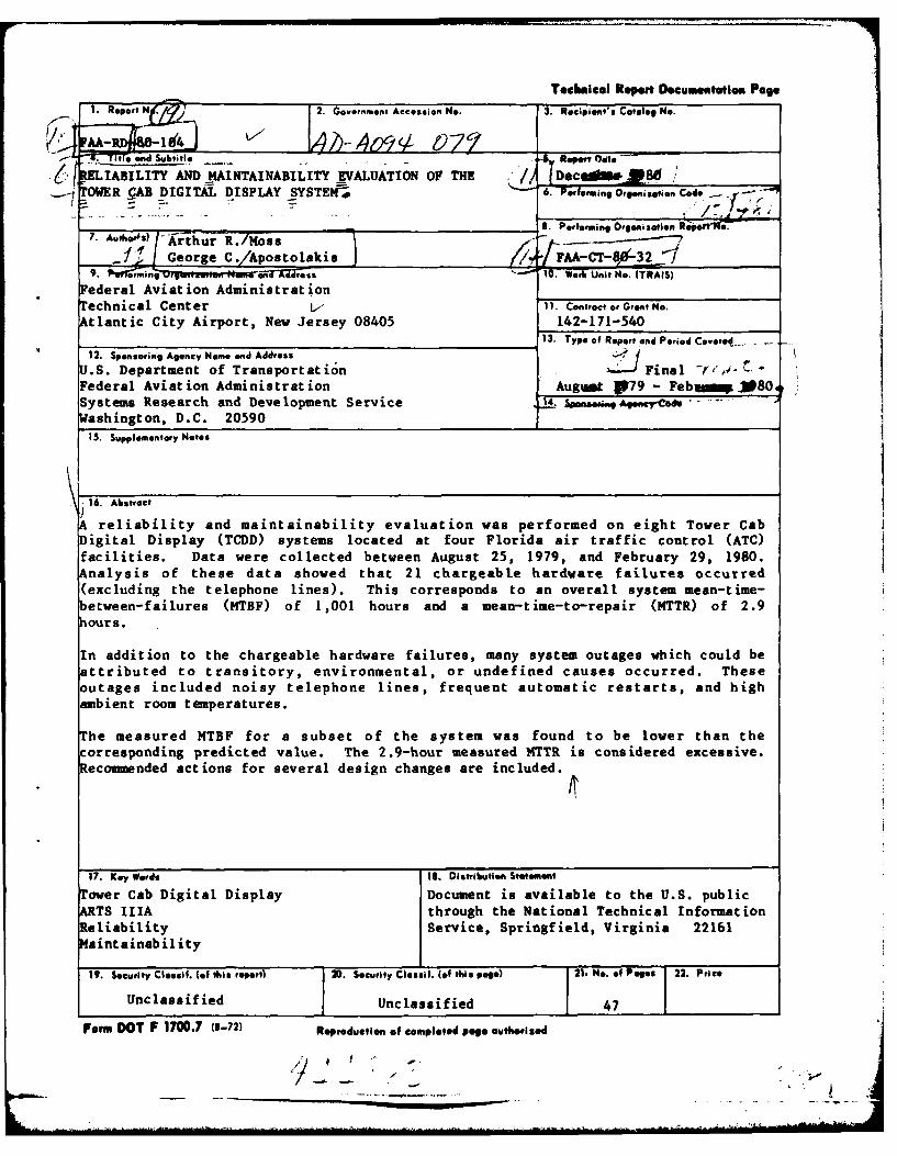
reliability and maintainability evaluation was performed on eight Tower CabDigital Display (TCDD) systems located at four Florida air traffic control (ATC)facilities. Data were collected between August 25, 1979, and February 29, 1980.Analysis of these data showed that 21 chargeable hardware failures occurred(excluding the telephone lines). This corresponds to an overall system mean-time-etween-failures (MTBF) of 1,001 hours and a mean-time-to-repair (MTTR) of 2.9hours.
In addition to the chargeable hardware failures, many system outages which could beattributed to transitory, environmental, or undefined causes occurred. Theseoutages included noisy telephone lines, frequent automatic restarts, and highambient room temperatures.
The measured MTBF for a subset of the system was found to be lower than thecorresponding predicted value. The 2.9-hour measured MTTR is considered excessive.Recommended actions for several design changes are included.
17. Key Wards IS. Distrlbution Statement
Tover Cab Digital Display Document is available to the U.S. publicATS IIIA through the National Technical InformationReliability Service, Springfield, Virginia 22161
Maintainability
19. Security Clessif. (of t*is report) 20. Security Clesef. (of this peso) 21. e. of Pegs 22. Price
Unclassified Unclassified 47
Form DOT P 1700.7 (8-72) Reproduction of completed page authoried
°
smlll lAll I a
2-5~: 9 2 h% sijil liii I i!! if .,
I I I I I SI It ,I II ' 9
01 6 I I w 9 9 t
S I * I I * II t III • IS 1I 3 II1IIiIII*
I II 11111J.-'il ,I's 1'4 13 J 2 inch"
i,,i iil ll ! " i"'il
ri
a a fi
-I I.. .01 --
PREFACE
The authors wish to express their appreciation to the FAA personnel at the Tampa,St. Petersburg, and Sarasota air traffic control facilities and to the personnel atMacDill Air Force Base for their assistance in this reliability and maintainabilityeffort. The thoroughness, accuracy, and completeness of the data which theyrecorded and made available to the FAA Technical Center personnel have contributedmaterially to the integrity of this analysis.
Accession For
NTIS GRA&IDTIC T11B
, ii
ri
TABLE OF CONTENTS
Page
INTRODUCTION 1
Purpose 1Background 1
SYSTEM DESCRIPTION I
DATA COLLECTION, REDUCTION, AND ANALYSIS 2
Data Collection 2Data Reduction and Analysis 2
RESULTS 14
NTBF and NTTR Summation (Chargeable Failures) 14Other System Outages 16Overall General Results 17
CONCLUS IONS 24
RECOMMENDATIONS 24
APPENDIX
v
LIST OF ILLUSTRATIONS
Figure Page
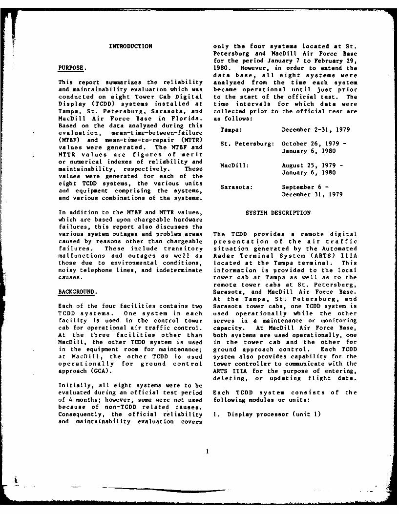
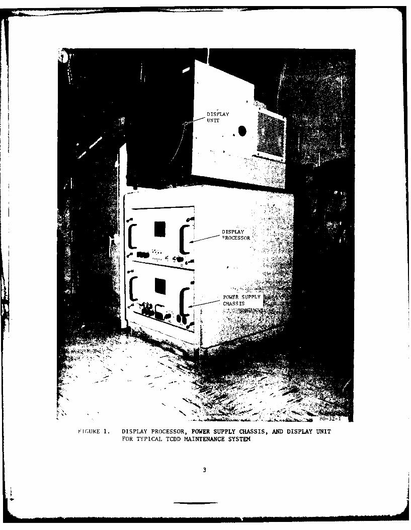
I Display Processor, Power Supply Chassis, and 3Display Unit for Typical TCDD Maintenance System
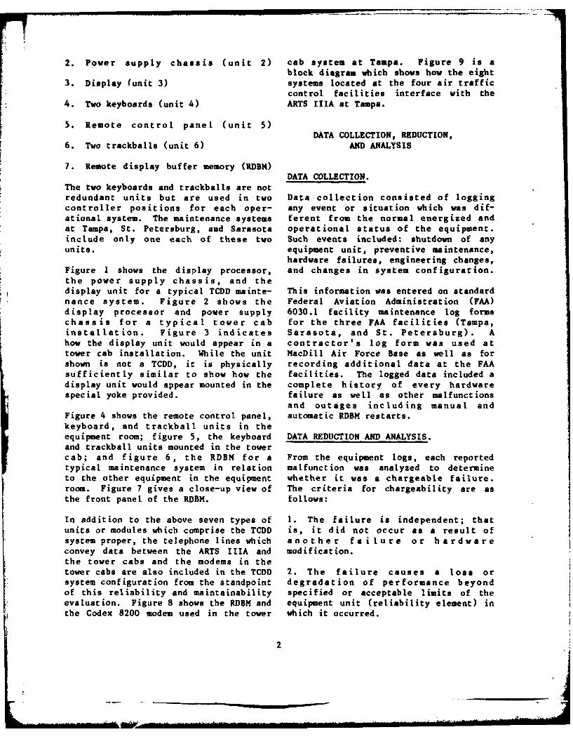
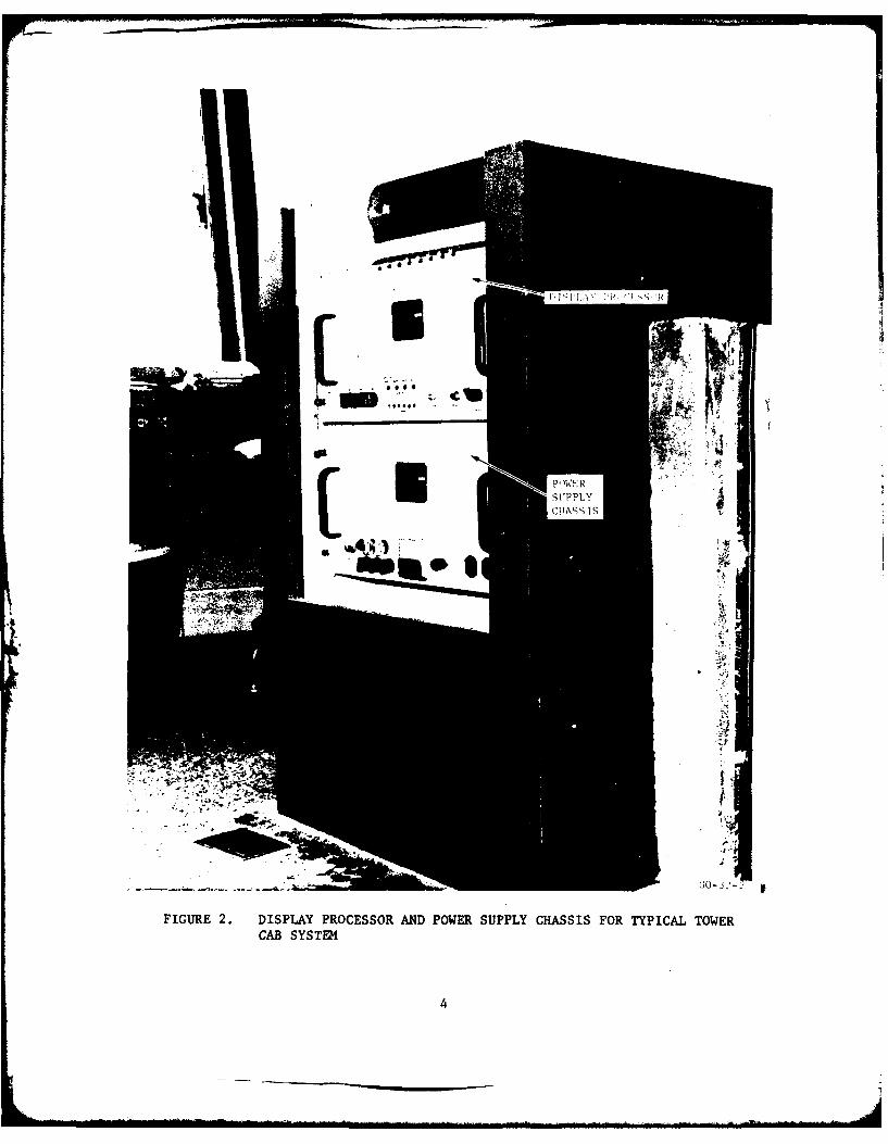
2 Display Processor and Power Supply Chassis for 4Typical Tower Cab System
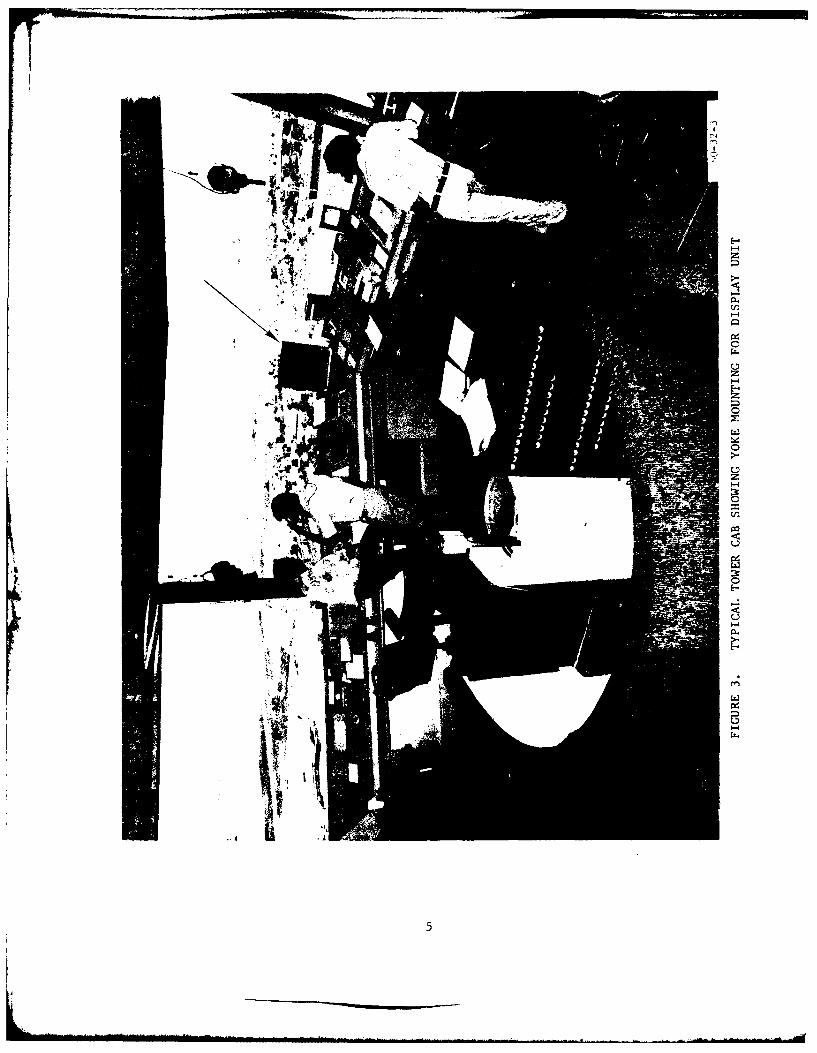
3 Typical Tower Cab Showing Yoke Mounting for 5Display Unit
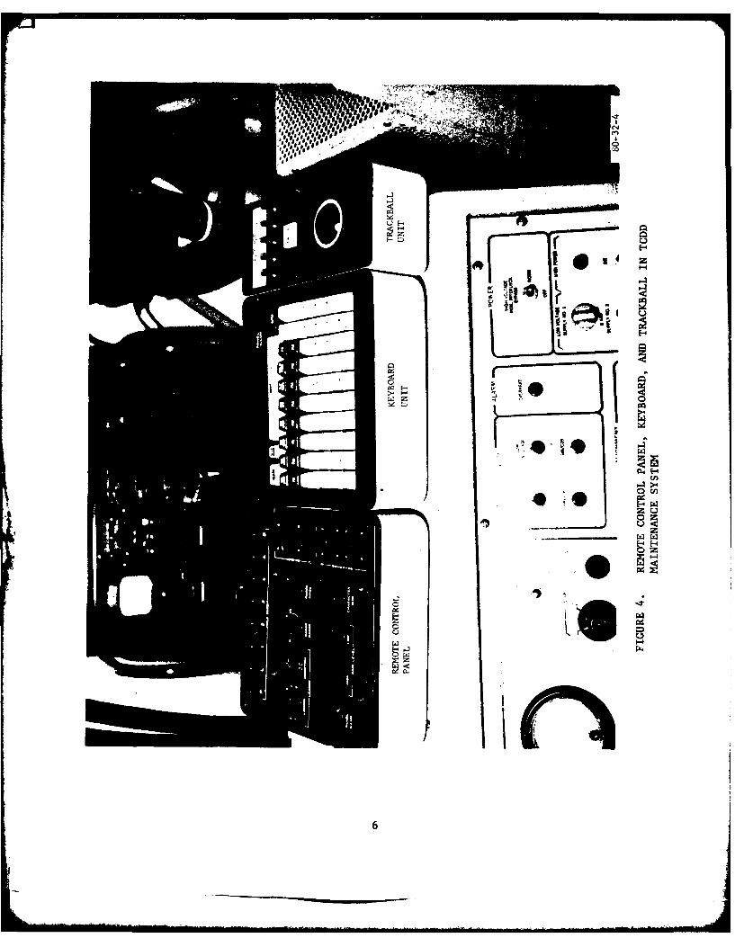
4 Remote Control Panel, Keyboard, and Trackball in 6
TCDD Maintenance System
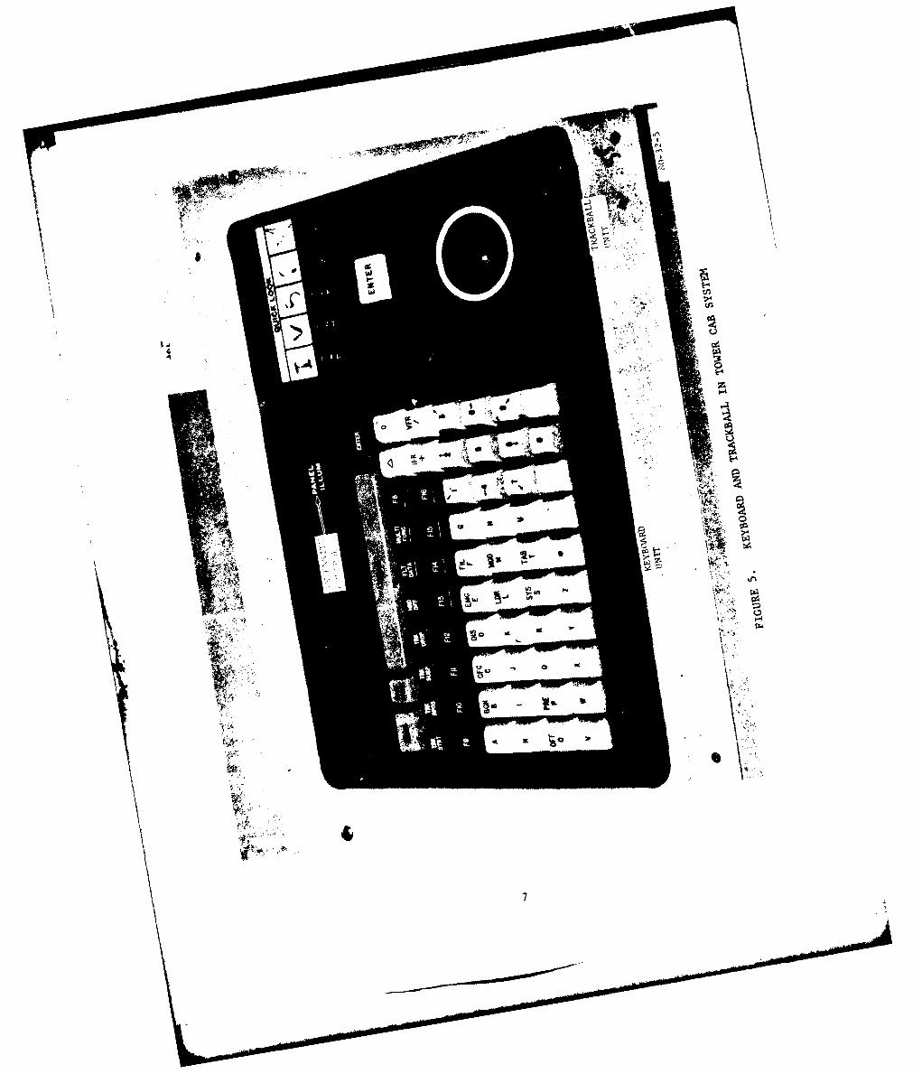
5 Keyboard and Trackball in Tower Cab System 7
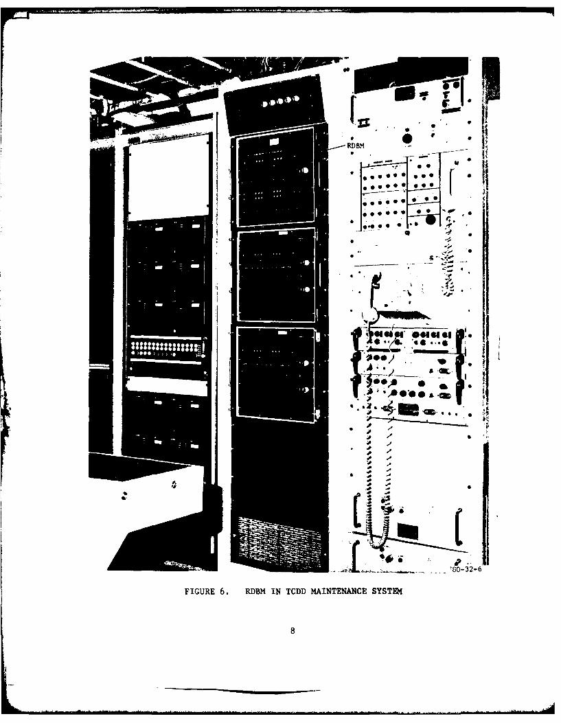
6 RDBM in TCDD Maintenance System 8
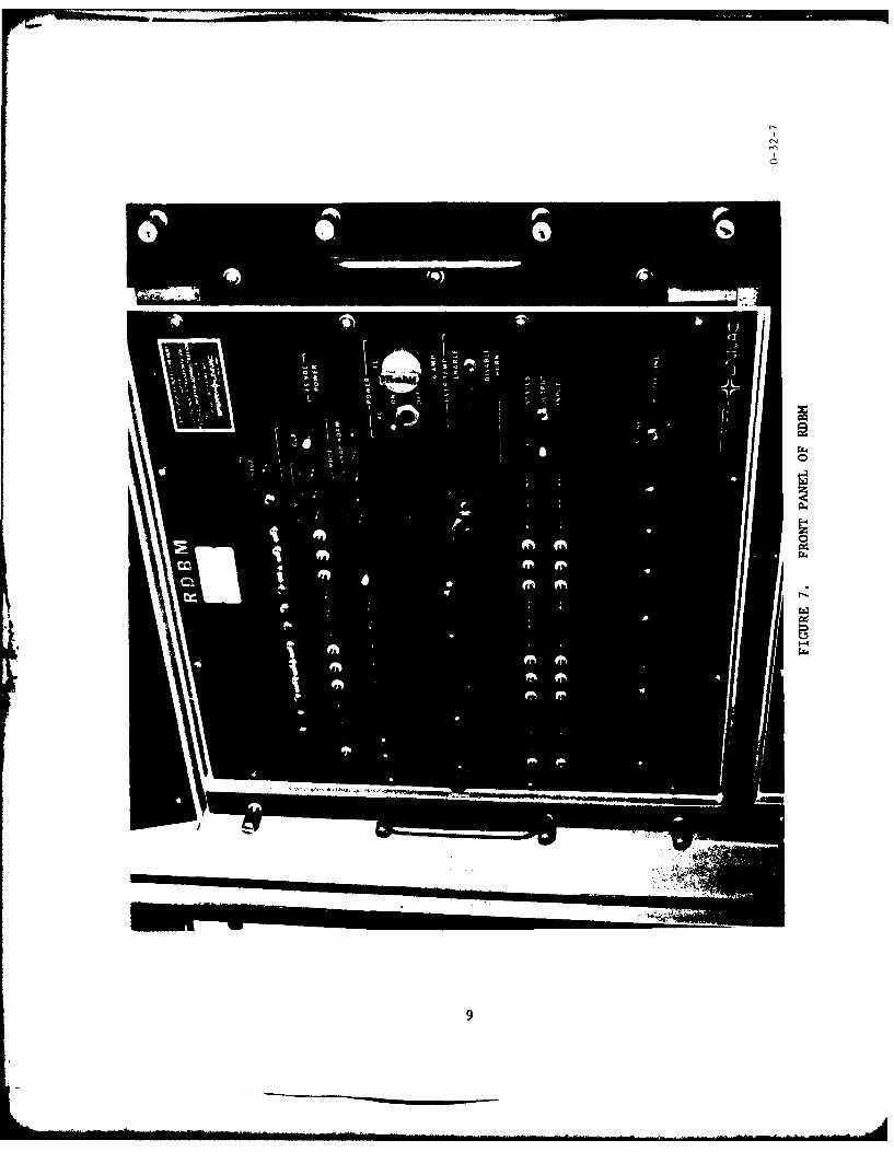
7 Front Panel of RDBM 9
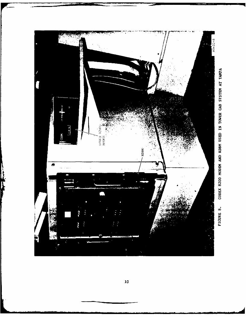
8 Codex 8200 Modem and RDBM used in 10Tower Cab System at Tampa
9 ARTS IliA Interface Diagram 11
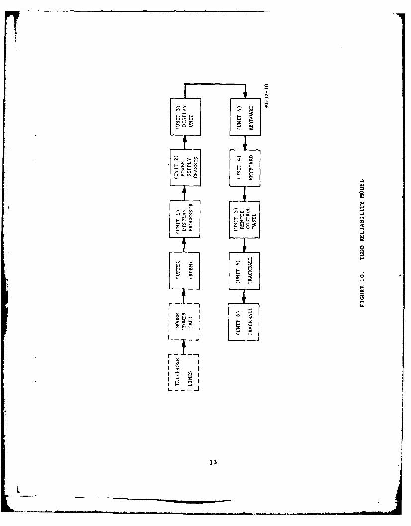
10 TCDD Reliability Model 13
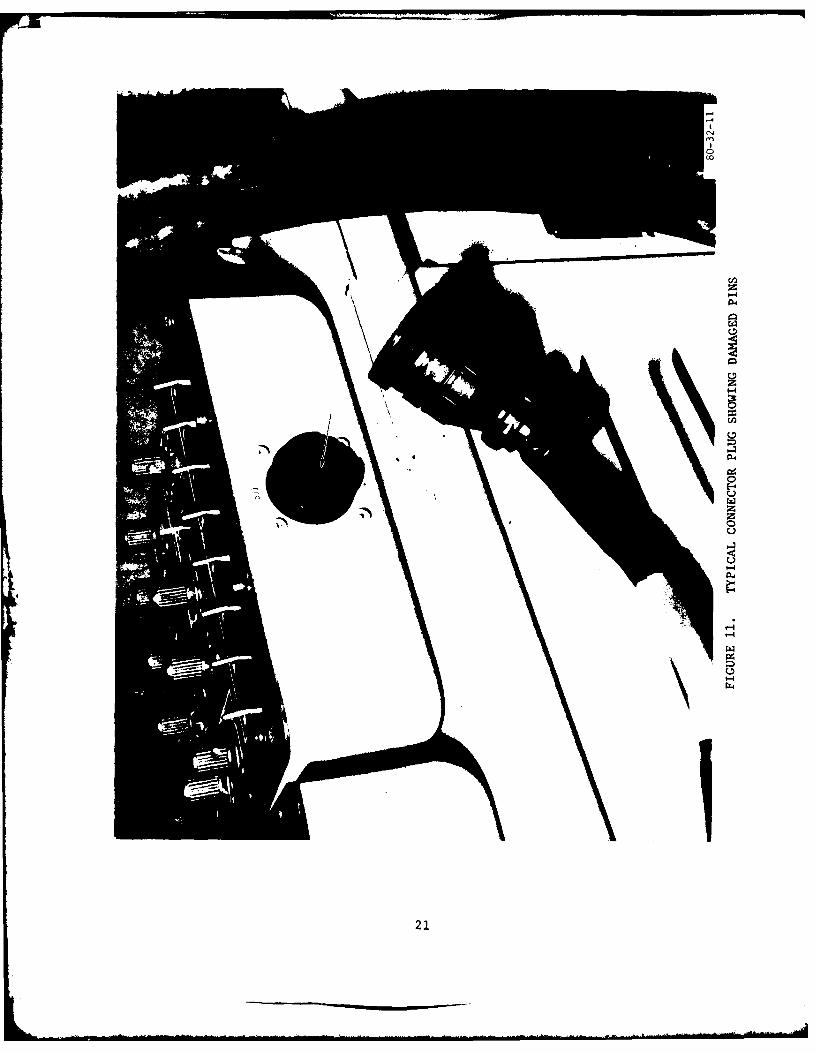
11 Typical Connector Plug Showing Damaged Pins 21
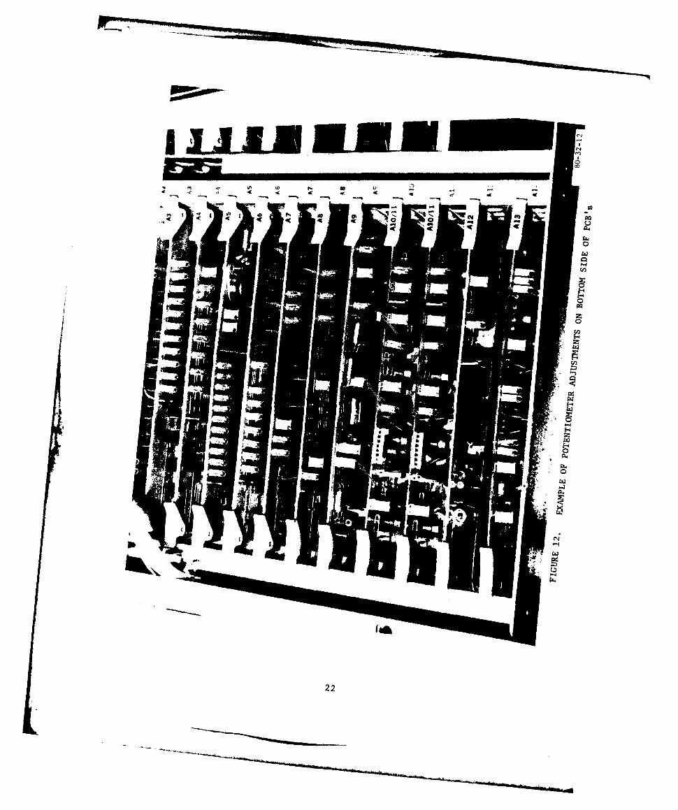
12 Example of Potentiometer Adjustments on 22Bottom Side of PCB's
LIST OF TABLES
Table Page
I Overall MTBF and MTTR Sumation 15
2 Predicted Versus Measured MTBF Values 18
3 Recommended MTBF Specification Values for TCDD 19
Equipment and System (Hrs)
vi
ii _ _ _ _ _ _ _ _ __ _ _ _ __ _
INTRODUCTION only the four systems located at St.Petersburg and MacDill Air Force Basefor the period January 7 to February 29,
PURPOSE. 1980. However, in order to extend thedata base, all eight systems were
This report summarizes the reliability analyzed from the time each systemand maintainability evaluation which was became operational until just priorconducted on eight Tower Cab Digital to the start of the official test. TheDisplay (TCDD) systems installed at time intervals for which data wereTampa, St. Petersburg, Sarasota, and collected prior to the official test areMacDill Air Force Base in Florida. as follows:Based on the data analyzed during thisevaluation, mean-time-between-failure Tampa: December 2-31, 1979(MTBF) and mean-time-to-repair (MTTR) St. Petersburg: October 26, 1979 -values were generated. The MTBF and January 6, 1980MTTR values are figures of meritor numerical indexes of reliability and MacDill: August 25 1979 -maintainability, respectively. These aauus 2, 1970values were generated for each of the January 6, 1980eight TCDD systems, the various units Sarasota: September 6 -and equipment comprising the systems, December 31, 1979and various combinations of the systems.
In addition to the MTBF and MTTR values, SYSTEM DESCRIPTIONwhich are based upon chargeable hardwarefailures, this report also discusses thevarious system outages and problem areas The TCDD provides a remote digitalcaused by reasons other than chargeable presentation of the air trafficfailures. These include transitory situation generated by the Automatedmalfunctions and outages as well as Radar Terminal System (ARTS) IlIAthose due to environmental conditions, located at the Tampa terminal. Thisnoisy telephone lines, and indeterminate information is provided to the localcauses, tower cab at Tampa as well as to the
remote tower cabs at St. Petersburg,BACKGROUND. Sarasota, and MacDill Air Force Base.
At the Tampa, St. Petersburg, andEach of the four facilities contains two Sarasota tower cabs, one TCDD system isTCDD systems. One system in each used operationally while the otherfacility is used in the control tower serves in a maintenance or monitoringcab for operational air traffic control. capacity. At MacDill Air Force Base,At the three facilities other than both systems are used operationally, oneMacDill, the other TCDD system is used in the tower cab and the other forin the equipment room for maintenance; ground approach control. Each TCDDat MacDill, the other TCDD is used system also provides capability for theoperationally for ground control tower controller to communicate with theapproach (GCA). ARTS IIIA for the purpose of entering,
deleting, or updating flight data.Initially, all eight systems were to beevaluated during an official test period Each TCDD system consists of theof 4 months; however, some were not used following modules or units:because of non-TCDD related causes.Consequently, the official reliability 1. Display processor (unit 1)and maintainability evaluation covers
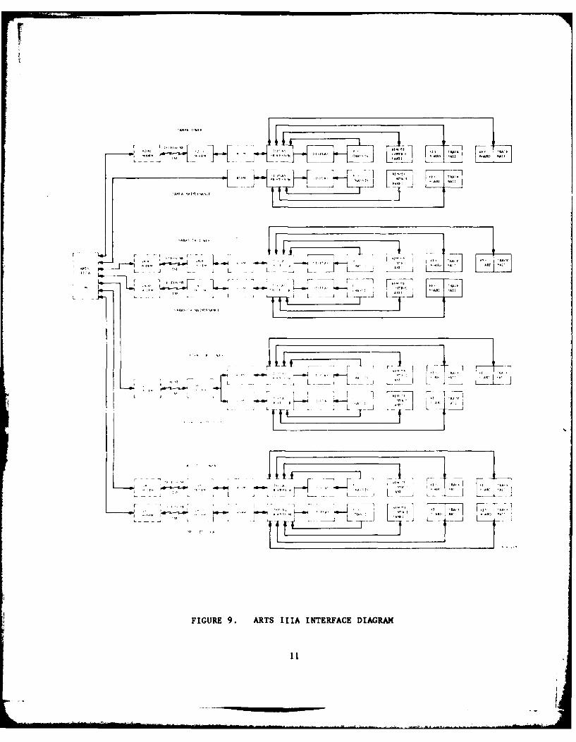
2. Power supply chassis (unit 2) cab system at Tampa. Figure 9 is ablock diagram which shows how the eight
3. Display (unit 3) systems located at the four air trafficcontrol facilities interface with the
4. Two keyboards (unit 4) ARTS IIIA at Tampa.
5. Remote control panel (unit 5)DATA COLLECTION, REDUCTION,
6. Two trackballs (unit 6) AND ANALYSIS
7. Remote display buffer memory (RDBM)
DATA COLLECTION.
The two keyboards and trackballs are notredundant units but are used in two Data collection consisted of loggingcontroller positions for each oper- any event or situation which was dif-ational system. The maintenance systems ferent from the normal energized andat Tampa, St. Petersburg, and Sarasota operational status of the equipment.include only one each of these two Such events included: shutdown of anyunits. equipment unit, preventive maintenance,
hardware failures, engineering changes,Figure I shows the display processor, and changes in system configuration.the power supply chassis, and thedisplay unit for a typical TCDD mainte- This information was entered on standardnance system. Figure 2 shows the Federal Aviation Administration (FAA)display processor and power supply 6030.1 facility maintenance log formschassis for a typical tower cab for the three FAA facilities (Tampa,installation. Figure 3 indicates Sarasota, and St. Petersburg). Ahow the display unit would appear in a contractor's log form was used attower cab installation. While the unit MacDill Air Force Base as well as forshown is not a TCDD, it is physically recording additional data at the FAAsufficiently similar to show how the facilities. The logged data included adisplay unit would appear mounted in the complete history of every hardwarespecial yoke provided, failure as well as other malfunctions
and outages including manual andFigure 4 shows the remote control panel, automatic RDBM restarts.keyboard, and trackball units in theequipment room; figure 5, the keyboard DATA REDUCTION AND ANALYSIS.and trackball units mounted in the towercab; and figure 6, the RDBM for a From the equipment logs, each reportedtypical maintenance system in relation malfunction was analyzed to determineto the other equipment in the equipment whether it was a chargeable failure.room. Figure 7 gives a close-up view of The criteria for chargeability are asthe front panel of the RDBM. follows:
In addition to the above seven types of 1. The failure is independent; thatunits or modules which comprise the TCDD is, it did not occur as a result ofsystem proper, the telephone lines which another failure or hardwareconvey data between the ARTS IIIA and modification.the tower cabs and the modems in thetower cabs are also included in the TCDD 2. The failure causes a loss orsystem configuration from the standpoint degradation of performance beyondof this reliability and maintainability specified or acceptable limits of theevaluation. Figure 8 shows the RDBM and equipment unit (reliability element) inthe Codex 8200 modem used in the tower which it occurred.
2
DISPLAYC U PROCESSOR
* ~ ~ 80-3.
F~IGIJIE 1. DISPLAY PROCESSOR, POWER SUPPLY CHASSIS, AND DISPLAY UNITFOR TYPICAL TCDD MAINTENANCE SYSTEM
Il
FIGURE 2. DISPLAY PROCESSOR AND POWER SUPPLY CHASSIS FOR TYPICAL TOWERCAB SYSTEK
0-4
E-4
z
C4
0l
44
r0
~g 410
40-
0CL
I 'Ir
la7
RDBM-
*..00goo
.0 00 * 0 I 1
.000)0**0
.A,
00''a
r.-'80-i2-6FIGURE~~ _ __B I DMANEACESSE
8I
z
44
C4
0
lz
Ad
100
c ~ ~~ ~~ L M -L taI I
.- ' L L I. .
A'. AI F_ - A - F - 7i
J L
I - -j L _ , I NI"It
___ ___ A A~ ' Aft ' l _ L _
A''.. . .' C A" : Al' A ll '
FIGURE 9. ARTS IIIA INTERFACE DIAGRAM
Ah LI 7
.... - i
3. The failure requires actual mainte- The values U and C were expressed in
nance effort to correct, as opposed to a terms of unit-hours. In the case of the
transient outage which can be reset or keyboards and trackballs, which are
saster-cleared. duplicated, U and C for each of thesetypes of units consist of the sum of the
In addition to these general criteria, a corresponding quantities for each
failure was charged against the tele- of the two units comprising the unit
phone line whenever sufficient degrada- type for a system.
tion occurred to call in the telephonecompany. Since an underlying exponential
(constant failure rate) statistical dis-
UNIT FAILURE RATES, MTBF's, and MTTR's. tribution is assumed for the failure and
The failure rates, MTBF's, and MTTR's repair rates, the following formulasfor each of the nine types of units were used for each type of unit:
comprising a TCDD system were thendetermined for each of the eight systems Nxl0 6
Failure rate ()- - failures perevaluated. This was done by determining U million hoursthe total uptime (U), total number ofchargeable failures (N), and total MTBF = U/N hoursrepair time (C) for each type of unitper system. These nine types of units, MTTR - C/N hourstogether with the number of anits pertype per system, are as follows:
SYSTEM FAILURE RATE, MTBF, AND MTTR. To
Unit Type No. of Units Per System compute the overall system failure rate,MTBF, and MTTR; a reliability model was
Display processor unit 1 employed to determine which of the unitsmust be operational to achieve full and
Power supply chassis I complete equipment functional capa-bility. This model is shown in figure
Display 1 10. All units are considered to be in aseries from a reliability standpoint.
Keyboards 2 The system failure rate, MTBF, and MTTRare expressed as follows:
Remote control panel 1 9
System failure rate (k s) = I ( ,i)Trackball 2~
Buffer I where Xi represents the failurerate of each of the nine unit types
Modem 1 comprising the system.
Telephone lines I System MTBF 106 / )Ls hours
All systems used Codex 4800 modems 9except for the following: System MTTR = . (A; x MTTR) hours
i-l As
Tampa - Codex 8200 modem (tower), no
modem in maintenance system In addition to the MTBF and MTTR determi-nation considering chargeable hardware
St. Petersburg - One Codex 9600 modem an t oneline caresly hisforboh twe an mintnace ysem and telephone line failures only, this
for both tower and maintenance system
12
z -z
ogo
13
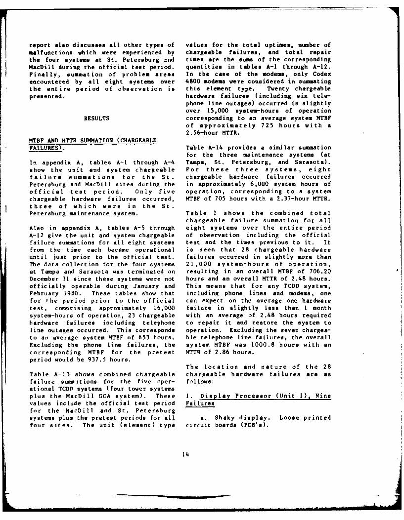
report also discusses all other types of values for the total uptimes, number ofmalfunctions which were experienced by chargeable failures, and total repairthe four systems at St. Petersburg :nd times are the sums of the corresponding
MacDill during the official test period, quantities in tables A-1 through A-12.Finally, summation of problem areas In the case of the modems, only Codexencountered by all eight systems over 4800 modems were considered in summatingthe entire period of observation is this element type. Twenty chargeablepresented. hardware failures (including six tele-
phone line outages) occurred in slightlyover 15,000 system-hours of operation
RESULTS corresponding to an average system MTEFof approximately 725 hours with a2.56-hour MTTR.
MTBF AND MTTR SUMMATION (CHARGEABLEFAILURES). Table A-14 provides a similar summation
for the three maintenance systems (atin appendix A, tables A-1 through A-4 Tampa, St. Petersburg, and Sarasota).show the unit and system chargeable For these three systems, eightfailure summations for the St. chargeable hardware failures occurredPetersburg and MacDill sites during the in approximately 6,000 system hours ofofficial test period. Only five operation, corresponding to a systemchargeable hardware failures occurred, MTBF of 705 hours with a 2.37-hour MTTR.three of which were in the St.Petersburg maintenance system. Table 1 shows the combined total
chargeable failure summation for all
Also in appendix A, tables A-5 through eight systems over the entire periodA-12 give the unit and system chargeable of observation including the officialfailure summations for all eight systems test and the times previous to it. Itfrom the time each became operational is seen that 28 chargeable hardwareuntil just prior to the official test. failures occurred in slightly more thanThe data collection for the four systems 21,000 system-hours of operation,at Tampa and Sarasota was terminated on resulting in an overall MTBF of 706.20December 31 since these systems were not hours and an overall MTTR of 2.48 hours.officially operable during January and This means that for any TCDD system,February 1980. These tables show that including phone lines and modems, onefor the period prior to the official can expect on the average one hardwaretest, comprising approximately 16,000 failure in slightly less than I monthsystem-hours of operation, 23 chargeable with an average of 2.48 hours requiredhardware failures including telephone to repair it and restore the system toline outages occurred. This corresponds operation. Excluding the seven chargea-to an average system MTBF of 653 hours. ble telephone line failures, the overallExcluding the phone line failures, the system MTBF was 1000.8 hours with ancorresponding MTBF for the pretest MTTR of 2.86 hours.period would be 937.5 hours.
The location and nature of the 28Table A-13 shows combined chargeable chargeable hardware failures are asfailure summrtions for the five oper- follows:ational TCDP systems (four tower systemsplus the MacDill GCA system). These 1. Display Processor (Unit 1), Ninevalues include the official test period Failuresfor the MscDill and St. Petersburgsystems plus the pretest periods for all a. Shaky display. Loose printedfour sites. The unit (element) type circuit boards (PCB's).
14
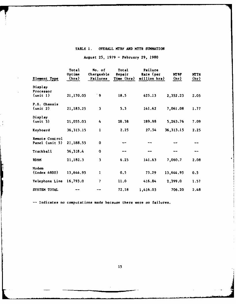
TABLE 1. OVERALL MTBF AND MTTR SUMMATION
August 25, 1979 - February 29, 1980
Total No. of Total FailureUptime Chargeable Repair Rate (per MTBF MTTR
Element Type (hrs) Failures Time (hrs) million hrs) (hr) (hr)
DisplayProcessor(unit 1) 21,170.05 9 18.5 425.13 2,352.23 2.05
P.S. Chassis(unit 2) 21,183.25 3 5.3 141.62 7,061.08 1.77
Display
(unit 3) 21,055.03 4 28.38 189.98 5,263.76 7.09
Keyboard 36,313.15 1 2.25 27.54 36,313.15 2.25
Remote ControlPanel (unit 5) 21,188.55 0 -- -- -- --
Trackball 36,318.4 0 -- --...
RDBM 21,182.3 3 6.25 141.63 7,060.7 2.08
Modem(Codex 4800) 13,644.95 1 0.5 73.29 13,644.95 0.5
Telephone Line 16,793.0 7 11.0 416.84 2,399.0 1.57
SYSTEM TOTAL .... 72.18 1,416.03 706.20 2.48
-- Indicates no computations made because there were no failures.
15
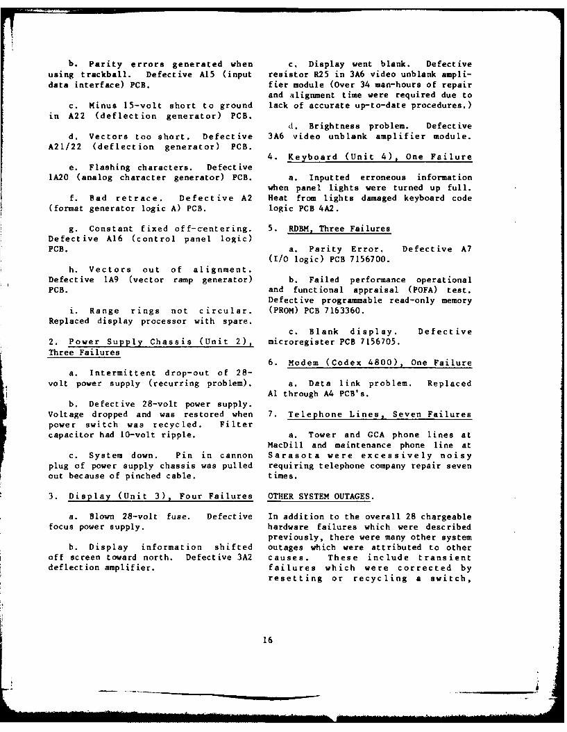
b. Parity errors generated when c. Display went blank. Defectiveusing trackball. Defective A15 (input resistor R25 in 3A6 video unblank ampli-data interface) PCB. fier module (Over 34 man-hours of repair
and alignment time were required due toc. Minus 15-volt short to ground lack of accurate up-to-date procedures.)
in A22 (deflection generator) PCB.d. Brightness problem. Defective
d. Vectors too short. Defective 3A6 video unblank amplifier module.A21/22 (deflection generator) PCB.
4. Keyboard (Unit 4), One Failuree. Flashing characters. Defective
1A20 (analog character generator) PCB. a. Inputted erroneous informationwhen panel lights were turned up full.
f. Bad retrace. Defective A2 Heat from lights damaged keyboard code(format generator logic A) PCB. logic PCB 4A2.
g. Constant fixed off-centering. 5. RDBM, Three FailuresDefective A16 (control panel logic)PCB. a. Parity Error. Defective A7
(I/O logic) PCB 7156700.h. Vectors out of alignment.
Defective 1A9 (vector ramp generator) b. Failed performance operationalPCB. and functional appraisal (POFA) test.
Defective programmable read-only memoryi. Range rings not circular. (PROM) PCB 7163360.
Replaced display processor with spare.c. Blank display. Defective
2. Power Supply Chassis (Unit 2), microregister PCB 7156705.Three Failures
6. Modem (Codex 4800), One Failurea. Intermittent drop-out of 28-
volt power supply (recurring problem). a. Data link problem. ReplacedAl through A4 PCB's.
b. Defective 28-volt power supply.Voltage dropped and was restored when 7. Telephone Lines, Seven Failurespower switch was recycled. Filtercapacitor had 10-volt ripple, a. Tower and GCA phone lines at
MacDill and maintenance phone line atc. System down. Pin in cannon Sarasota were excessively noisy
plug of power supply chassis was pulled requiring telephone company repair sevenout because of pinched cable, times.
3. Display (Unit 3), Four Failures OTHER SYSTEM OUTAGES.
a. Blown 28-volt fuse. Defective In addition to the overall 28 chargeablefocus power supply. hardware failures which were described
previously, there were many other systemb. Display information shifted outages which were attributed to other
off screen toward north. Defective 3A2 causes. These include transientdeflection amplifier, failures which were corrected by
resetting or recycling a switch,
16
automatic restarts or master clears, 4. Environmental Problems - Twountraceable noise on telephone lines, instances of degraded performancefailures due to environmental causes, occurred at the St. Petersburg facilityand failures due to indeterminate as a result of too high an ambientcauses. These are summarized below for temperature in the maintenance system.the four systems at St. Petersburg and In each case, when the room temperatureMacDill for the official test period reached 90* F, the degradation mani-only (January 7 to February 29, 1980). fested itself. In one case, the displayThese outages were not considered to be was shaky; in the other case, rangechargeable. rings were flattened on the right side.
In addition to these two cases observed1. Automatic Restarts - Over 40 during the official test, two similarautomatic RDBM restarts were logged at cases were observed at St. PetersburgMacDill Air Force Ease between January 4 during the pretest period.and February 11. Some were caused bysystem reconfigurat ions, some by noise OVERALL GENERAL RESULTS.on the telephone lines, and still othersby hardware glitches. The causes of the 1. System Summary Without Telephonevery intermittent restarts are difficult Lines - As discussed previously,to determine, table 1 provides on overall summary for
all eight systems, including the2. Display Blanking - Three instances telephone lines. As seen from thisof display blanking occurred at MacDill table, seven of the 28 chargeableAir Force Base. One resulted in a failures occurred in the telephone2-hour outage because of an ARTS IIIA lines. If these were excluded fromcommunications multiplexer controller consideration, the overall system MTBFoutage at Tampa. The second instance would then become 1001 hours with ainvolved 6 hours of intermittent 2.9-hour MTTR. This would correspond toperiodic display blanking caused by RDBM an average of one chargeable failurerestarts which were attributed to noisy occurring every 1.4 months with anand marginal telephone lines. The third average time of 2.9 hours required toinstance also was due to numerous restore the system to normal operation.automatic restarts necessitated byexcessive phone line noise. 2. Measured Versus Predicted MTBF -
As discussed above, the overall measuredAt St. Petersburg, five instances of MTBF obtained using all collected datadisplay blanking occurred. As at for all eight systems (less telephoneMacDill, all of these occurred during lines) was 1001 hours. While a cor-January. One was transitory and was responding predicted value is notcorrected by an RDBM reset. Three available for comparison, predictedothers were also transitory and were failure rates and MTBF's for variousreset by recycling the power switch of portions of the configuration arethe 9600 modem. The fifth was caused by available in the contractor's reliablityhuman error when a plug was inad- design plan. Table 2 shows thesevertently pulled out during maintenance, predicted values compared to the corre-
sponding measured values taken from3. Phone Line Problems - Noisy phone table 1.lines constituted a recurring problemat MacDill, which uses a Codex 4800 For a TCDD system not including themodem in contrast to St. Petersburg, RDBM, modem, or telephone lines, awhich uses a Codex 9600 modem. The measured MTBF of 1,275 hours wasnoisy phone lines at MacDill were a obtained. This is lower than thefactor in the automatic restarts and corresponding predicted value of 1,736display blankings. hours. The overall measured MTBF for
17
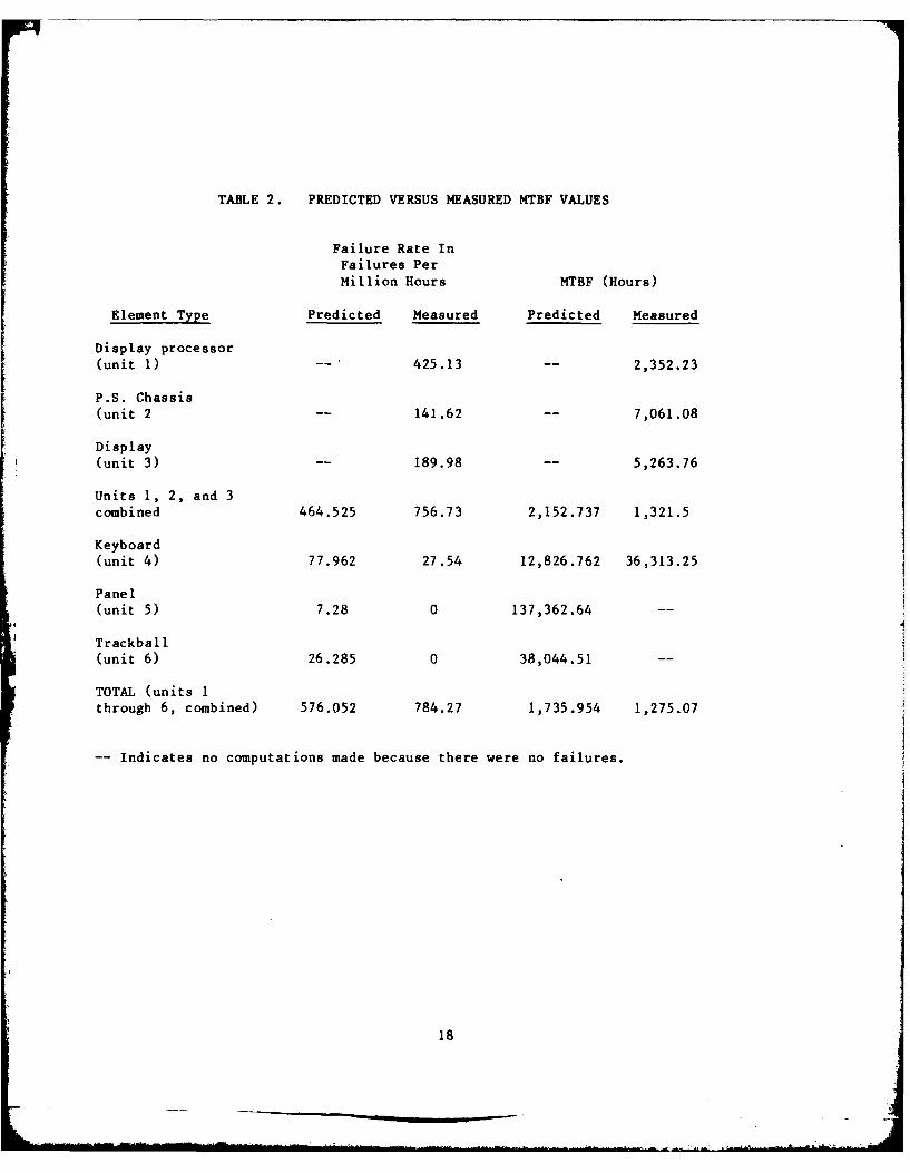
TABLE 2. PREDICTED VERSUS MEASURED MTBF VALUES
Failure Rate InFailures Per
Million Hours MTBF (Hours)
Element Type Predicted Measured Predicted Measured
Display processor(unit 1) -- 425.13 2,352.23
P.S. Chassis(unit 2 -- 141.62 7,061.08
Display(unit 3) -- 189.98 -- 5,263.76
Units 1, 2, and 3combined 464.525 756.73 2,152.737 1,321.5
Keyboard(unit 4) 77.962 27.54 12,826.762 36,313.25
Panel(unit 5) 7.28 0 137,362.64 --
Trackball(unit 6) 26.285 0 38,044.51
TOTAL (units 1through 6, combined) 576.052 784.27 1,735.954 1,275.07
-- Indicates no computations made because there were no failures.
18
the display processor, display unit, and of the activity. The weekly preventivepower supply chassis, combined, is 1,322 maintenance activities included specialhours, which is lower than the cor- diagnostic POFA tests which exercise theresponding predicted value of 2,153 logic in the various elements or unitshours. of the system.
The display processor showed the lowest 4. Codex 4800 Versus 9600 Modems -measured MTBF (2,325 hours) of any During most of this evaluation, the St.of the elements in the system. The Petersburg facility was equipped with atelephone lines had the second lowest Codex 9600 modem and the Sarasota andmeasured MTBF (2,399 hours). MacDill facilities with Codex 4800
modems. The Codex 4800 modem was used
It is seen from table 2 that the with an unconditioned telephone line andobserved MTBF for a system configuration was sensitive to noise. This situation,which does not include the RDBM, modem, especially at MacDill, contributed toor telephone lines is 1275 hours versus such undesirable effects as automatica corresponding predicted value of 1736 restarts and jittery displays. On-sitehours. personnel observed that the Codex 9600
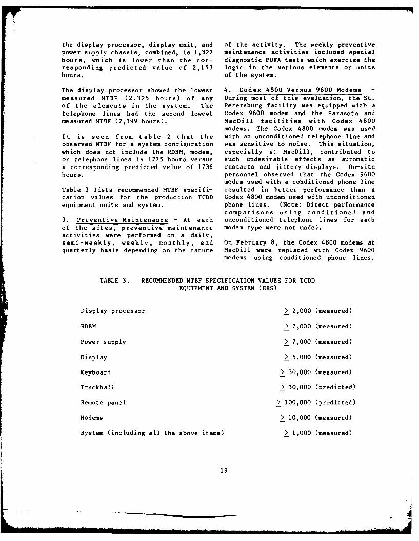
modem used with a cohditioned phone lineTable 3 lists recommended MTBF specifi- resulted in better performance than acation values for the production TCDD Codex 4800 modem used with unconditionedequipment units and system, phone lines. (Note: Direct performance
comparisons using conditioned and
3. Preventive Maintenance - At each unconditioned telephone lines for eachof the sites, preventive maintenance modem type were not made).activities were performed on a daily,semi-weekly, weekly, monthly, and On February 8, the Codex 4800 modems atquarterly basis depending on the nature MacDill were replaced with Codex 9600
modems using conditioned phone lines.
TABLE 3. RECOMMENDED MTBF SPECIFICATION VALUES FOR TCDDEQUIPMENT AND SYSTEM (HRS)
Display processor > 2,000 (measured)
RDBM > 7,000 (measured)
Power supply > 7,000 (measured)
Display > 5,000 (measured)
Keyboard > 30,000 (measured)
Trackball > 30,000 (predicted)
Remote panel > 100,000 (predicted)
Modems > 10,000 (measured)
System (including all the above items) > 1,000 (measured)
19
_"Amok"
These were operated at 9600- and 7. Miscellaneous Problems4800-bit-per-second rates for experi-mental purposes. The 9600-bit rate was a. Keyboard Heat Problem - Atobserved by on-site personnel to have St. Petersburg, erroneous data werepositive benefits among which were: (1) outputted from the keyboard when therestarts lasted only 2 to 3 seconds; (2) panel was at its highest lightkeyboard, trackball, and quick-look intensity. The keyboard code logic PCBentries responded faster; and (3) the was damaged by the excessive heattracking range did not fluctuate as it generated. Figure 5 shows thiswould have at the 4800-bit rate. intensity control on the keyboard.
Even at a 4800-bit rate, site personnel b. Bent Pins - The pins on thereported that the Codex 9600 modem would display processor PCB's are easily bentbe advantageous because it can accom- if they are not properly aligned beforemodate noise which may cause jitter with insertion. In addition, bent pin prob-the Codex 4800 modem. lems occurred in the connector plugs
going into the keyboard, trackball, andBy the end of this evaluation period, remote panel. The problem here is thatall sites had been equipped with Codex there are plastic rings in the connector9600 modems and were awaiting con- plugs which engage the pins before theditioning of the telephone lines, keying slots make contact, thereby bend-
ing the pins. Figure 11 shows a typical5. Alignment Problems - At Sarasota, connector plug with damaged pins.difficulty was encountered in aligningthe system after replacing the cathode c. PCB Potentiometers - Many ofray tube (CRT) which had been burned out the potentiometers mounted on PCB's haveas a result of a -15-volt short circuit, adjustments on the bottom side ratherSeveral iterative realignments were than the top edge of the PCB's. Annecessary before satisfactory per- example of this is shown in figure 12.formance was restored. The use of an extender board is
required whenever it becomes necessaryAlso at Sarasota, after another CRT to align the potentiometer. Thisreplacement, alignment and trouble- involves (1) powering down the equip-shooting times were excessively long. ment, (2) inserting the extender board,This was caused by inaccurate obsolete (3) restoring power, (4) making theprocedures, many of which did not alignment, (5) removing power, (6)reflect hardware changes. removing the extender board, and (7)
restoring power. All this increases the6. Environmental Problems - On four MTTR.separate occasions, blinking, shakytargets, or other abnormal display 8. Replaced PCB's and Modules - Theconditions were noted in the St. following PCB's and modules werePetersburg maintenance system where the replaced during the period of thisambient temperature in the equipment reliability and maintainabilityroom reached 90" F. evaluation:
20
z
2,
E-4
:30
CL)
0.4
210
4C -C 4
E-4
22
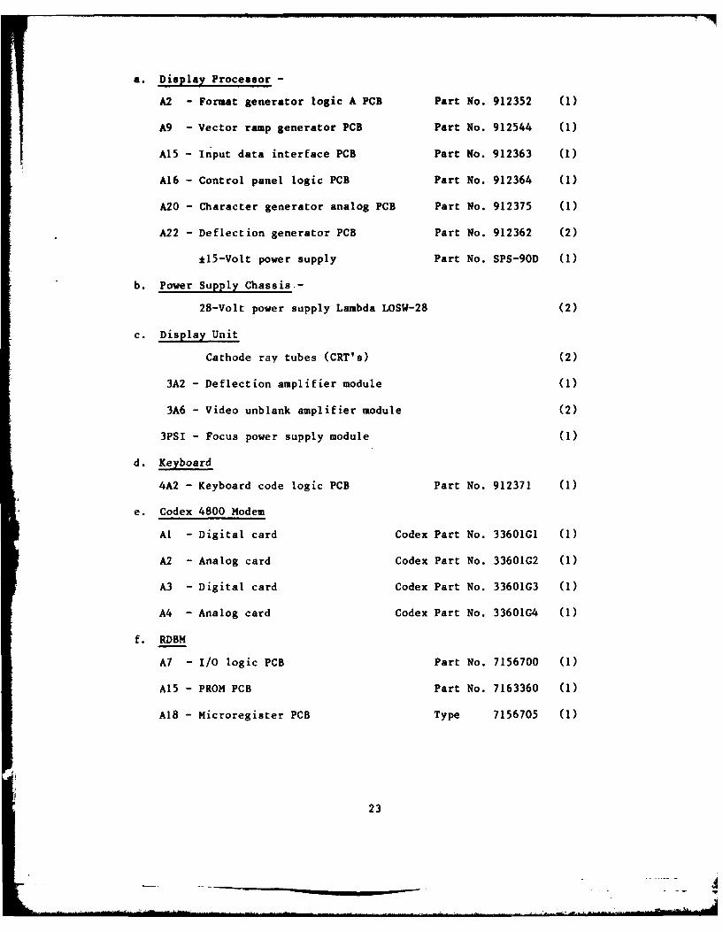
a. Display Processor -
A2 - Format generator logic A PCB Part No. 912352 (1)
A9 - Vector ramp generator PCB Part No. 912544 (1)
A15 - Input data interface PCB Part No. 912363 (1)
A16 - Control panel logic PCB Part No. 912364 (1)
A20 - Character generator analog PCB Part No. 912375 (1)
A22 - Deflection generator PCB Part No. 912362 (2)
*15-Volt power supply Part No. SPS-90D (1)
b. Power Supply Chassis.-
28-Volt power supply Lambda LOSW-28 (2)
c. Display Unit
Cathode ray tubes (CRT's) (2)
3A2 - Deflection amplifier module (1)
3A6 - Video unblank amplifier module (2)
3PSI - Focus power supply module (1)
d. Keyboard
4A2 - Keyboard code logic PCB Part No. 912371 (1)
e. Codex 4800 Modem
Al - Digital card Codex Part No. 33601G1 (1)
A2 - Analog card Codex Part No. 33601G2 (1)
A3 - Digital card Codex Part No. 33601G3 (1)
A4 - Analog card Codex Part No. 33601G4 (1)
f. RDBM
A7 - I/O logic PCB Part No. 7156700 (1)
A15 - PROM PCB Part No. 7163360 (1)
A18 - Microregister PCB Type 7156705 (1)
23
It has been reported that an RDBM- 4. Degradation of equipment per-resident TCDD diagnostic has been formance in the maintenance room
developed and is currently being occurred when the ambient room tempera-implemented in the Tampa TCDD systems. ture reached 90* F. Normal performanceThis diagnostic was not available to was restored when the temperature
maintenance technicians during the test dropped to 80" F or 85* F.period. The MTTR values for the dis-play subsystem, therefore, may improve 5. Erroneous data were outputted from
as this new diagnostic becomes the keyboard when the panel display
available. light intensity was fully illuminated.The keyboard code logic printed circuitboard (PCB) failed because of the
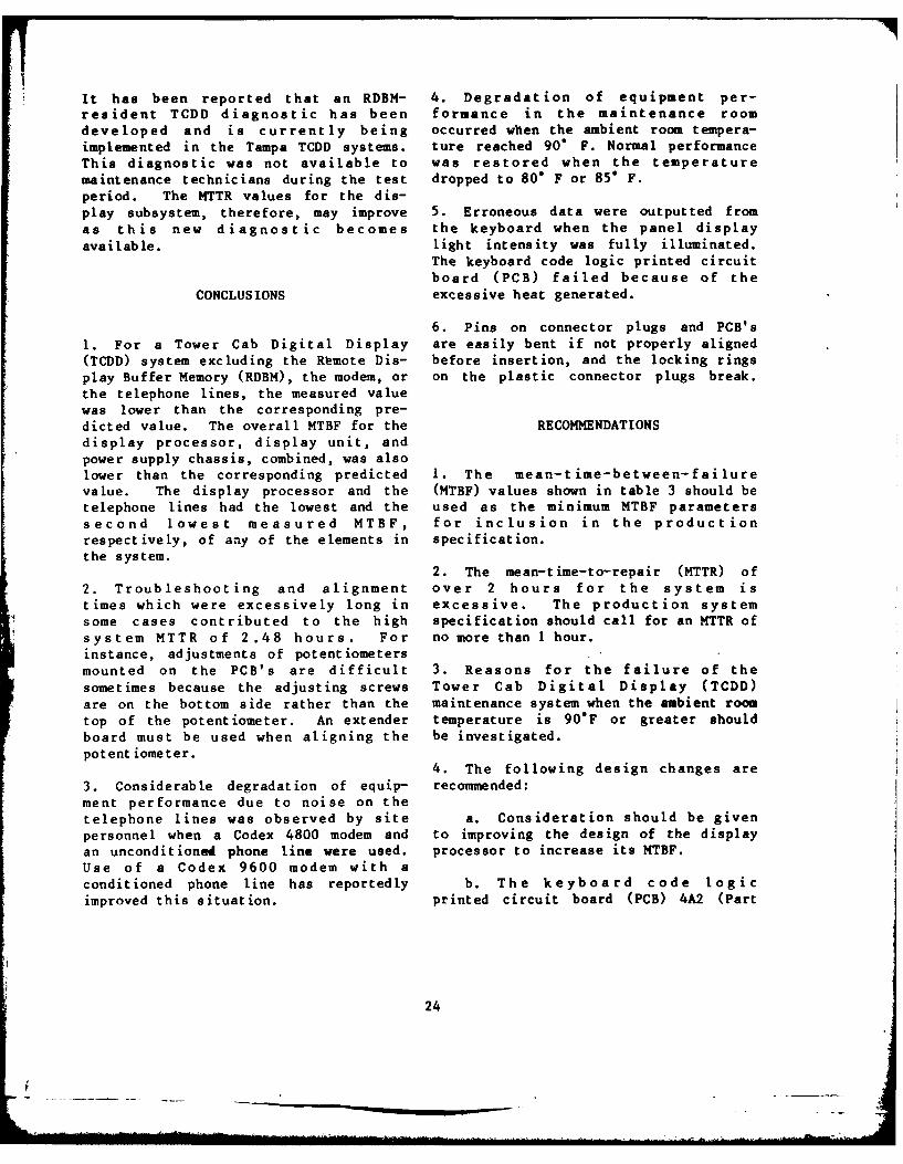
CONCLUSIONS excessive heat generated.
6. Pins on connector plugs and PCB's
I. For a Tower Cab Digital Display are easily bent if not properly aligned(TCDD) system excluding the Remote Dis- before insertion, and the locking rings
play Buffer Memory (RDBM), the modem, or on the plastic connector plugs break.
the telephone lines, the measured valuewas lower than the corresponding pre-dicted value. The overall MTBF for the RECOMMENDATIONSdisplay processor, display unit, and
power supply chassis, combined, was alsolower than the corresponding predicted I. The mean-time-between-failurevalue. The display processor and the (MTBF) values shown in table 3 should betelephone lines had the lowest and the used as the minimum MTBF parameterssecond lowest measured MTBF, for inclusion in the production
respectively, of any of the elements in specification.the system.
2. The mean-time-to-repair (MTTR) of
2. Troubleshooting and alignment over 2 hours for the system istimes which were excessively long in excessive. The production systemsome cases contributed to the high specification should call for an MTTR of
system MTTR of 2.48 hours. For no more than 1 hour.instance, adjustments of potentiometersmounted on the PCB's are difficult 3. Reasons for the failure of the
sometimes because the adjusting screws Tower Cab Digital Display (TCDD)are on the bottom side rather than the maintenance system when the ambient room
top of the potentiometer. An extender temperature is 90"F or greater shouldboard must be used when aligning the be investigated.
potent iometer.4. The following design changes are
3. Considerable degradation of equip- recommended:ment performance due to noise on thetelephone lines was observed by site a. Consideration should be given
personnel when a Codex 4800 modem and to improving the design of the displayan unconditioned phone line were used. processor to increase its MTBF.Use of a Codex 9600 modem with aconditioned phone line has reportedly b. The keyboard code logic
improved this situation, printed circuit board (PCB) 4A2 (Part
24
No. 912371), which is contained within e. Consideration should be giventhe keyboard assembly (unit 4), should to having all display alignments in theeither be redesigned or possibly display unit rather than in the displayrelocated so that its performance will processor as is now done. Alignmentnot be adversely affected by the heat of the display unit would be easier andgenerated when the panel light is turned the MTTR reduced.up to full intensity. Temperaturemeasurements should be made to help f. To provide more flexibleisolate the problem. installation, consideration should be
given to increasing the allowable cablec. The PCB's and connector plugs length between the RDBM and the display
should be examined to determine design processor from its present limit of 200improvements which would allow for their feet.easier insertion without bending thepins. 5. Comparative tests under controlled
conditions should be made with thed. Consideration should be given TCDD system using Codex 4800 and 9600
to mounting the potentiometers on the modems with both conditioned andtop edge of the PCB's to allow adjust- unconditioned telephone lines for eachment without using an extender board, type of modem. Based on data obtainedThis change would save the time required from such tests, an appropriate recom-to turn the system off and on when mendation concerning use of modems andinserting and removing the extender telephone lines could be made.board, thereby reducing the MTTR.
25
APPENDIX A
MTBF AND KTTR SUMMATIONS
LIST OF TABLES
Table Page
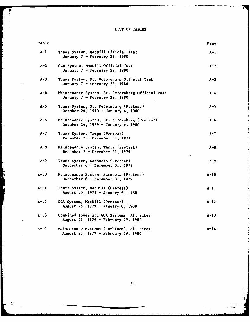
A-i Tower System, MacDill Official Test A-iJanuary 7 - February 29, 1980
A-2 GCA System, MacDill Official Test A-2January 7 - February 29, 1980
A-3 Tower System, St. Petersburg Official Test A-3January 7 - February 29, 1980
A-4 Maintenance System, St. Petersburg Official Test A-4January 7 - February 29, 1980
A-5 Tower System, St. Petersburg (Pretest) A-5October 26, 1979 - January 6, 1980
A-6 Maintenance System, St. Petersburg (Pretest) A-6October 26, 1979 - January 6, 1980
A-7 Tower System, Tampa (Pretest) A-7December 2 - December 31, 1979
A-8 Maintenance System, Tampa (Pretest) A-8December 2 - December 31, 1979
A-9 Tower System, Sarasota (Pretest) A-9September 6 - December 31, 1979
A-10 Maintenance System, Sarasota (Pretest) A-10September 6 - December 31, 1979
A-i1 Tower System, MacDill (Pretest) A-ilAugust 25, 1979 - January 6, 1980
A-12 GCA System, MacDill (Pretest) A-12August 25, 1979 - January 6, 1980
A-13 Combined Tower and GCA Systems, All Sites A-13August 25, 1979 - February 29, 1980
A-14 Maintenance Systems (Combined), All Sites A-14August 25, 1979 - February 29, 1980
A-i
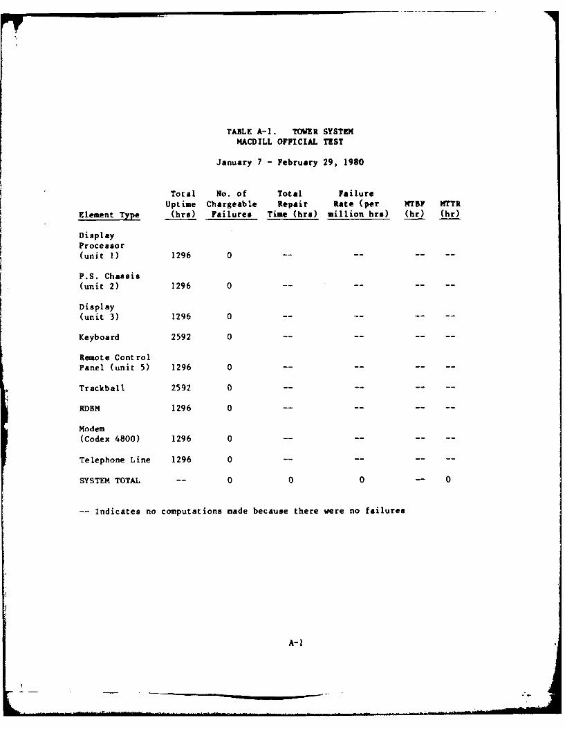
TABLE A-1. TOWER SYSTEMMACDILL OFFICIAL TEST
January 7 - February 29, 1980
Total No. of Total FailureUptime Chargeable Repair Rate (per HTBF MTTR
Element Type (bra) Failures Time (hr.) million bra) (hr) .(hr)
DisplayProcesasor(unit 1) 1296 0 --- -
P.S. Chassis(unit 2) 1296 0 ---- -
Display
(unit 3) 1296 0 --- -
Keyboard 2592 0 --- -
Remote Control
Panel (unit 5) 1296 0 --- -
4 Trackball 2592 0--- -
RDBM 1296 0 --- -
Modem(Codex 4800) 1296 0 --- -
Telephone Line 1296 0 --- -
SYSTEM TOTAL -- 0 0 0 -- 0
-Indicates no computations made because there vere no failures
A-1
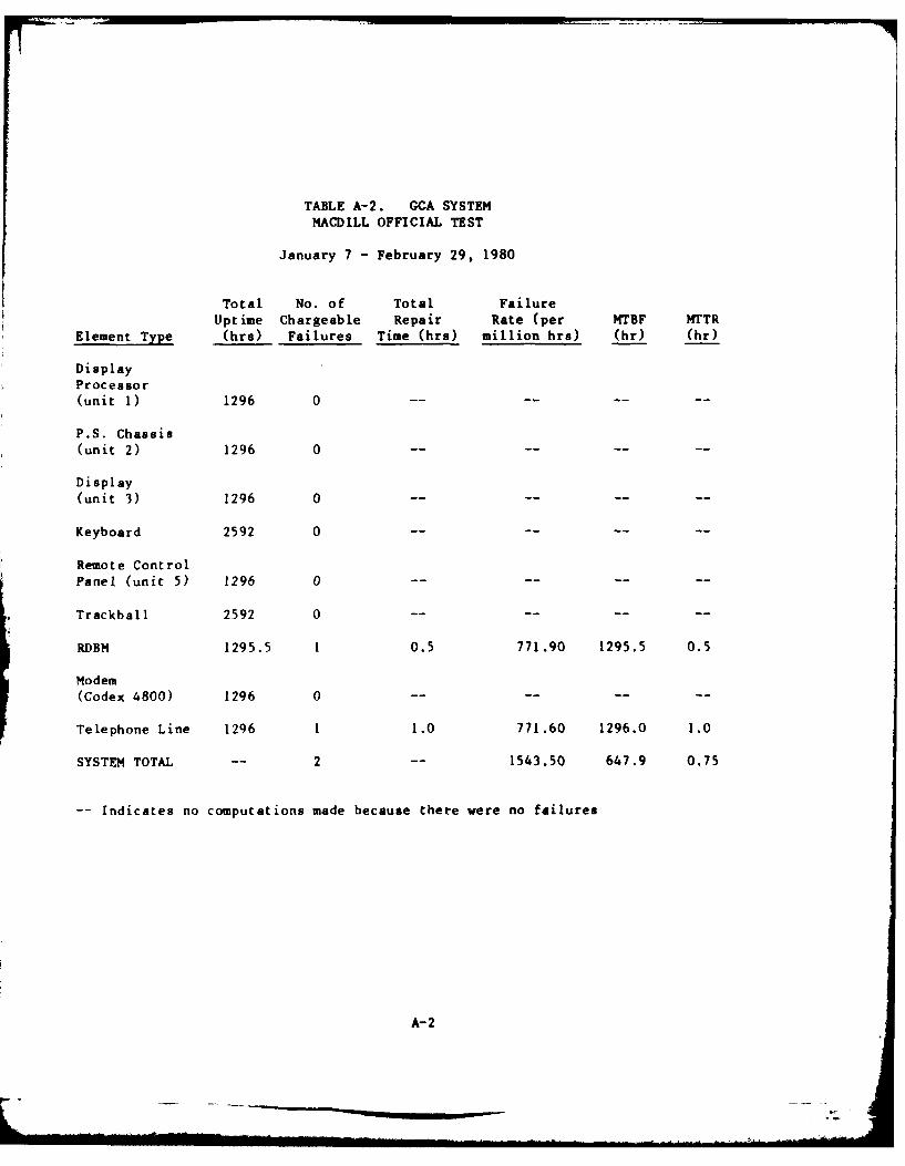
TABLE A-2. GCA SYSTEMMACDILL OFFICIAL TEST
January 7 -February 29, 1980
Total No. of Total FailureUptime Chargeable Rear Rate (per MTBF MTTR
Element Type (bra) Failures Time (hrs) million hrs) (hr) (hr)
DisplayProcessor(unit 1) 1296 0 --- -
P.S. Chassis(unit 2) 1296 0 --- -
Display(unit 3) 1296 0 - --
Keyboard 2592 0 --- -
Remote Control
Panel (unit 5) 1296 0 --- -
Trackball 2592 0 -- -- -- --
RDBM 1295.5 1 0.5 771.90 1295.5 0.5
Modem(Codex 4800) 1296 0 -- -- -- --
Telephone Line 1296 1 1.0 771.60 1296.0 1.0
SYSTEM TOTAL -- 2 -- 1543.50 647.9 0.75
-Indicates no computations made because there were no failures
A- 2
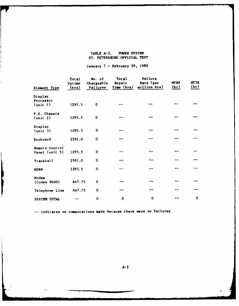
TABLE A-3. TOWER SYSTEMST. PETERSBURG OFFICIAL TEST
January 7 -February 29, 1980
Total No. of Total FailureUptime Chargeable Repair Rate (per MTBF MTTR
Element Type (hr.) -Failures Time Chre) million hrs) (hr) (hr)
DisplayProcessor(unit 1) 1295.5 0- -- -
P.S. Chassis(unit 2) 1295.5 0 --- -
Display(unit 3) 1295.5 0 -----
Keyboard 2591.0 0 --- -
Remote Control
Panel (unit 5) 1295.5 0 --- -
Trackball 2591.0 0 -----
RDBM 1295.5 0 --- -
Modem(Codex 9600) 647.75 0 -----
Telephone Line 647.75 0- -- -
SYSTEM TOTAL -- 0 0 0 -- 0
-- indicates no computations made because there were no failures
A- 3
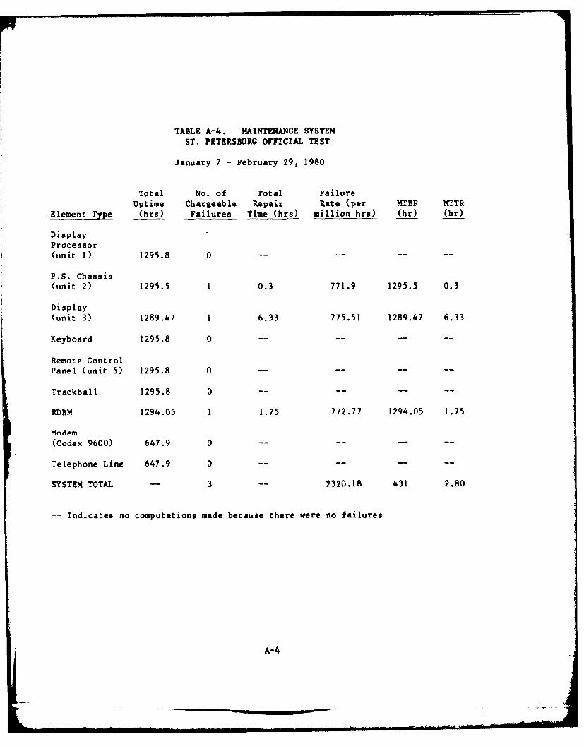
TABLE A-4. MAINTENANCE SYSTEMST. PETERSBURG OFFICIAL TEST
January 7 - February 29, 1980
Total No. of Total FailureUptime, Chargeable Repair Rate (per MTBF MTTR
Element Type (hrs) Failures Time (hrs) million hrs) (hr) (hr)
DisplayProcessor(unit 1) 1295.8 0 --- -
P.S. Chassis(unit 2) 1295.5 1 0.3 771.9 1295.5 0.3
Display
(unit 3) 1289.47 1 6.33 775.51 1289.47 6.33
Keyboard 1295.8 0 -- -- -- --
Remote Control
Panel (unit 5) 1295.8 0 --- -
Trackball 1295.8 0 -- -- -- --
RDBM 1294.05 1 1.75 772.77 1294.05 1.75
Modem(Codex 9600) 647.9 0 --- -
Telephone Line 647.9 0 ---- -- --
SYSTEM TOTAL -- 3 -- 2320.18 431 2.80
-Indicates no computations made because there were no failures
A-4
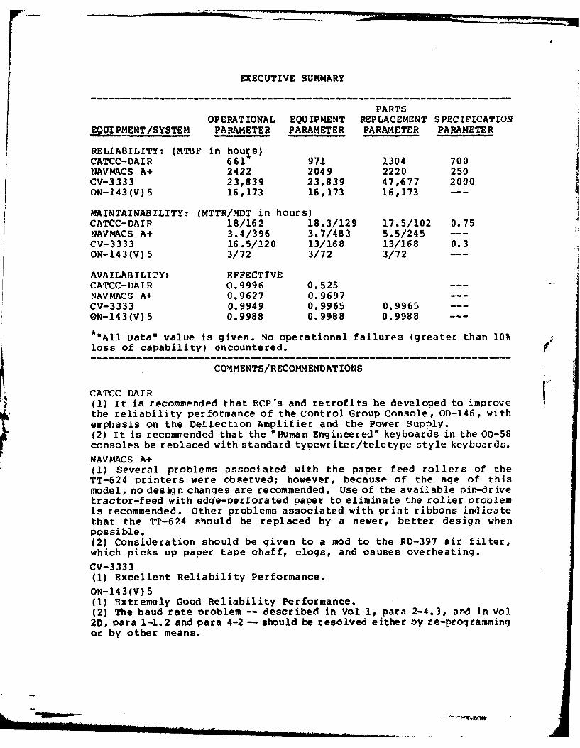
EXECUTIVE SUMMARY
PARTSOPERATIONAL EQUIPMENT REPLACEMENT SPECIFICATION
E9UIPMENT/SYSTEM PARAMETER PARAMETER PARAMETER PARAMETER
RELIABILITY: (MTBF in hours)CATCC-DAIR 661- 971 1304 700NAVMACS A+ 2422 2049 2220 250CV-3333 23,839 23,839 47,677 2000ON-143(V)5 16,173 16,173 16,173
MAINTAINABILITY: (MTTR/MDT in hours)CATCC-DAIR 18/162 18.3/129 17.5/102 0.75NAVMACS A+ 3.4/396 3.7/483 5.5/245 ---CV-3333 16.5/120 13/168 13/168 0.3ON-143(V)5 3/72 3/72 3/72
AVAILABILITY: EFFECTIVE
CATCC-DAIR 0.9996 0.525 ---NAVMACS A+ 0.9627 0.9697CV-3333 0.9949 0.9965 0.9965 ---
ON-143(V)5 0.9988 0.9988 0.9988 ---
*"All Data" value is given. No operational failures (greater than 10%
loss of capability) encountered.
COMMENTS/RECOMMENDATIONS
CATCC DAIR(C) It is recommended that ECP's and retrofits be develoned to improve
the reliability performance of the Control Group Console, OD-146, withemphasis on the Deflection Amplifier and the Power Supply.(2) It is recommended that the "Human Engineered" keyboards in the OD-58consoles be replaced with standard typewriter/teletype style keyboards.
NAVMACS A+(I) Several problems associated with the paper feed rollers of theTT-624 printers were observed; however, because of the age of thismodel, no design changes are recommended. Use of the available pin-drivetractor-feed with edqe-perforated paper to eliminate the roller problemis recommended. Other problems associated with print ribbons indicatethat the TT-624 should be replaced by a newer, better design whenpossible.(2) Consideration should be given to a mod to the RD-397 air filter,which picks up paper tape chaff, clogs, and causes overheating.
CV-3333(1) Excellent Reliability Performance.
ON-143(V) 5(1) Extremely Good Reliability Performance.(2) The baud rate problem -- described in Vol 1, para 2-4.3, and in Vol2D, para 1-1.2 and para 4-2 - should be resolved either by re-proqrammingor by other means.
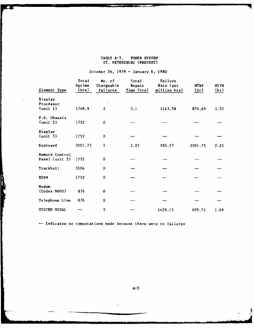
TABLE A-5. TOWER SYSTEM
ST. PETERSBURG (PRETEST)
October 26, 1979 - January 6, 1980
Total No. of Total FailureUptime Chargeable Repair Rate (per MTBF MTTR
Element Type (hrs) Failures Time (hrs) million hrs) (hr) (hr)
DisplayProcessor(unit 1) 1748.9 2 3.1 1143.58 874.45 1.55
P.S. Chassis(unit 2) 1752 0 -- -- -- --
Display
(unit 3) 1752 0 -- -- -- --
Keyboard 3501.75 1 2.25 285.57 3501.75 2.25
Remote Control
Panel (unit 5) 1752 0 -- -- --
Trackball 3504 0 ....
RDBM 1752 0 ....
Modem(Codex 9600) 876 0 ........
Telephone Line 876 0 -- -- --
SYSTEM TOTAL -- 3 1429.15 699.72 1.69
-- Indicates no computations made because there were no failures
A-5
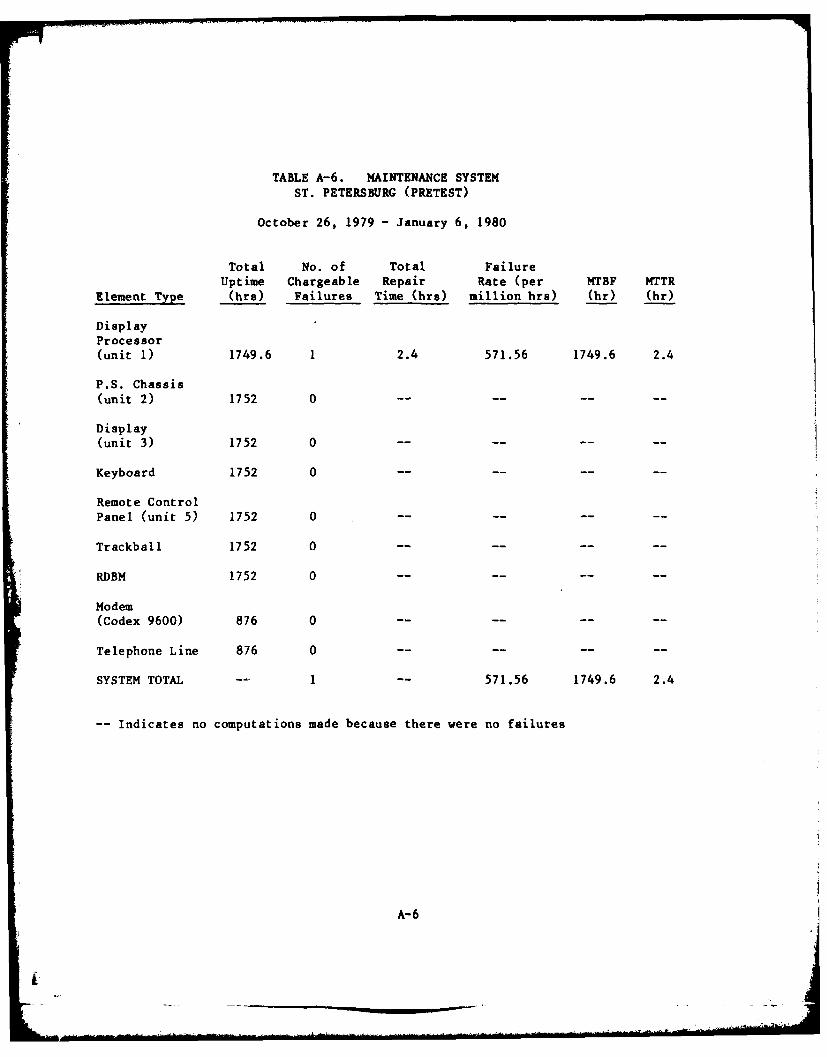
TABLE A-6. MAINTENANCE SYSTEMST. PETERSBURG (PRETEST)
October 26, 1979 - January 6, 1980
Total No. of Total FailureUptime Chargeable Repair Rate (per MTBF MTTR
Element Type Chra) Failures Time (bre) million hrs) (hr) (hr)
DisplayProcessor(unit 1) 1749.6 1 2.4 571.56 1749.6 2.4
P.S. Chassis(unit 2) 1752 0 -- -- -- --
Display(unit 3) 1752 0 --- -
Keyboard 1752 0- -- -
Remote Control
Panel (unit 5) 1752 0 --- -
Trackball 1752 0 --- -
RDBM 1752 0 --- -
Modem
(Codex 9600) 876 0 --- -
Telephone Line 876 0 ---- -- --
SYSTEM TOTAL -1 -- 571.56 1749.6 2.4
-Indicates no computations made because there were no failures
A-6
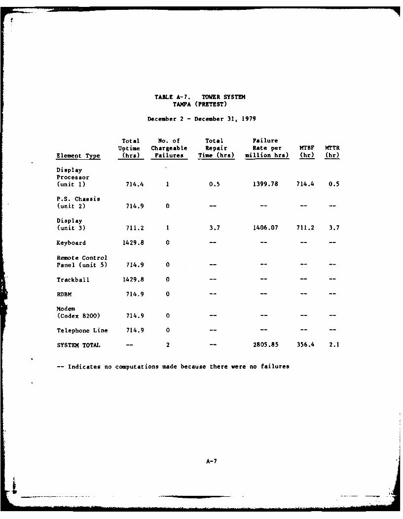
TABLE A-7. TOWER SYSTEMTAMPA (PRETEST)
December 2 - December 31, 1979
Total No. of Total FailureUptime Chargeable Repair Rate per MTBF MTTR
Element Type (hrs) Failures Time (hrs) million hrs) (hr) (hr)
DisplayProcessor(unit 1) 714.4 1 0.5 1399.78 714.4 0.5
P.S. Chassis(unit 2) 714.9 0 -- -- -- --
Display(unit 3) 711.2 1 3.7 1406.07 711.2 3.7
Keyboard 1429.8 0 -- -- -- --
Remote Control
Panel (unit 5) 714.9 0
Trackball 1429.8 0
RDBM 714.9 0
Modem(Codex 8200) 714.9 0 ...... ..
Telephone Line 714.9 0 -- -- --
SYSTEM TOTAL -- 2 -- 2805.85 356.4 2.1
-- Indicates no computations made because there were no failures
A-7
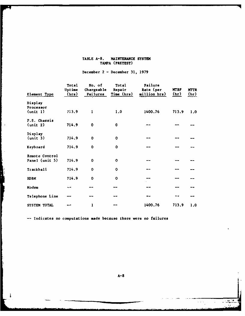
TABLE A-8. MAINTENANCE SYSTEMTAMPA (PRETEST)
December 2 - December 31, 1979
Total No. of Total FailureUptime Chargeable Repair Rate (per MTBF NTTR
Element Type (hrs) Failures Time (hra) million hrs) (hr) (hr)
DisplayProcessor(unit 1) 713.9 1 1.0 1400.76 713.9 1.0
P.S. Chassis(unit 2) 714.9 0 0 .... ..
Display(unit 3) 714.9 0 0 .... ..
Keyboard 714.9 0 0 .... ..
Remote ControlPanel (unit 5) 714.9 0 0 .... ..
Trackball 714.9 0 0 .... ..
RDBM 714.9 0 0 .... ..
Modem .......... ..
Telephone Line .......... ..
SYSTEM TOTAL -- 1 -- 1400.76 713.9 1.0
-- Indicates no computations made because there were no failures
A-8
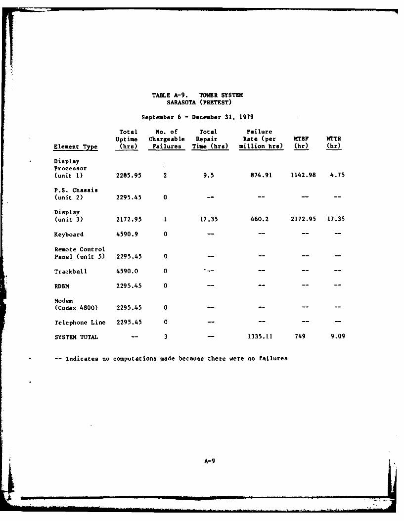
TABLE A-9. TOWER SYSTEM
SARASOTA (PRETEST)
September 6 - December 31, 1979
Total No. of Total Failure
Uptime Chargeable Repair Rate (per MTBF MTTR
Element Tpe (hrs) Failures Time (hrs) million hra) (hr) (hr)
DisplayProcessor(unit 1) 2285.95 2 9.5 874.91 1142.98 4.75
P.S. Chassis(unit 2) 2295.45 0
Display(unit 3) 2172.95 1 17.35 460.2 2172.95 17.35
Keyboard 4590.9 0 ........
Remote ControlPanel (unit 5) 2295.45 0 ....
Trackball 4590.0 0 --......
RDBM 2295.45 0 ........
Modem(Codex 4800) 2295.45 0 ........
Telephone Line 2295.45 0 ........
SYSTEM TOTAL -- 3 -- 1335.11 749 9.09
-- Indicates no computations made because there were no failures
A-9
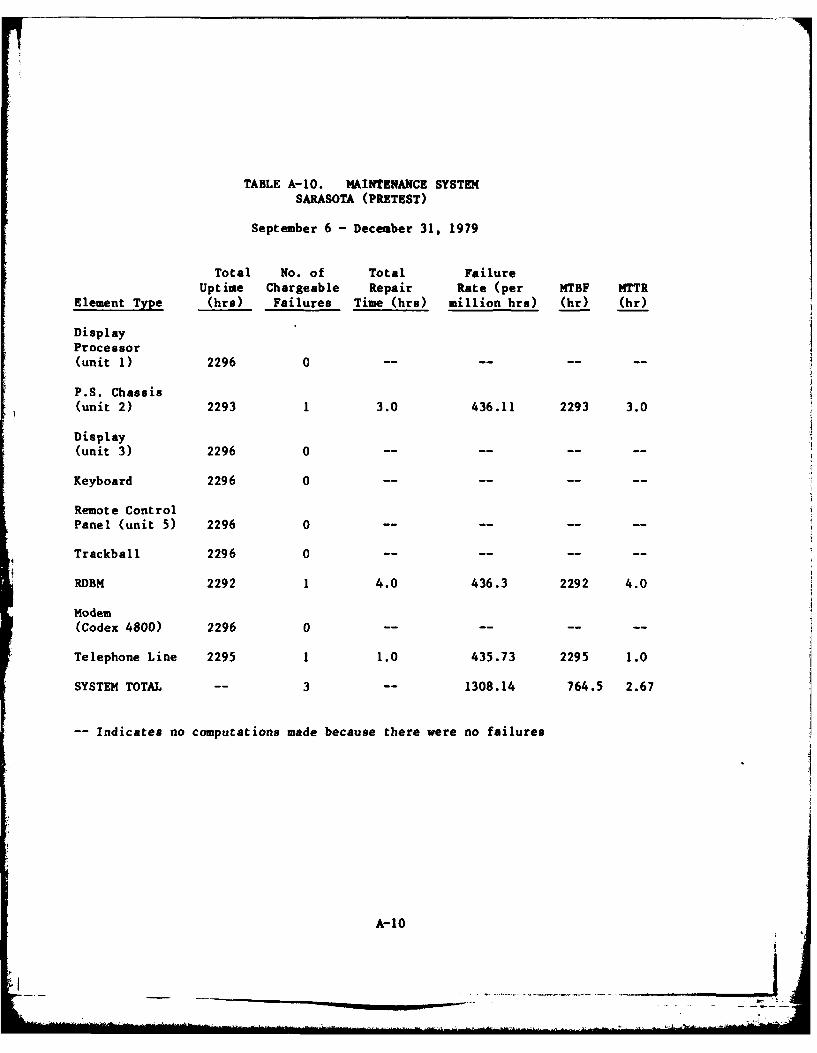
TABLE A-10. MAINTENANCE SYSTEMSARASOTA (PRETEST)
September 6 -December 31, 1979
Total No. of Total FailureEeetT Uptime Chargeable Repair Rate (per MTBF MTTR
Elmn ype (hrs) Failures Time (bra) million hrs) (hr) (hr)
DisplayProcessor(unit 1) 2296 0- -- -
P.S. Chassis(unit 2) 2293 1 3.0 436.11 2293 3.0
Display
(unit 3) 2296 0 --- -
Keyboard 2296 0- -- -
Remote Control
Panel (unit 5) 2296 0 --- -
Trackball 2296 0 -- -- -- --
RDBM 2292 1 4.0 436.3 2292 4.0
Modem
(Codex 4800) 2296 0 -- -- -- --
Telephone Line 2295 1 1.0 435.73 2295 1.0
SYSTEM TOTAL -- 3 -- 1308.14 764.5 2.67
-Indicates no computations made because there were no failures
A- 10
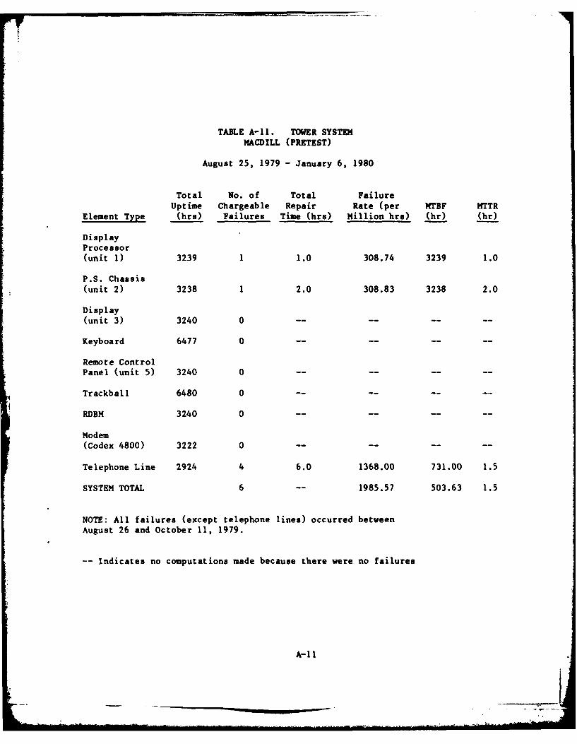
TABLE A-II. TOWER SYSTEMMACDILL (PRETEST)
August 25, 1979 - January 6, 1980
Total No. of Total FailureUptime Chargeable Repair Rate (per ITBF MTTR
Element Type (hrs) Failures Time (hra) Million hrs) (hr) (hr)
DisplayProcessor(unit 1) 3239 1 1.0 308.74 3239 1.0
P.S. Chassis(unit 2) 3238 1 2.0 308.83 3238 2.0
Display(unit 3) 3240 0 ........
Keyboard 6477 0 ........
Remote ControlPanel (unit 5) 3240 0 ........
Trackball 6480 0 ........
RDBM 3240 0 ........
Modem(Codex 4800) 3222 0 ........
Telephone Line 2924 4 6.0 1368.00 731.00 1.5
SYSTEM TOTAL 6 -- 1985.57 503.63 1.5
NOTE: All failures (except telephone lines) occurred betweenAugust 26 and October 11, 1979.
-- Indicates no computations made because there were no failures
A-il
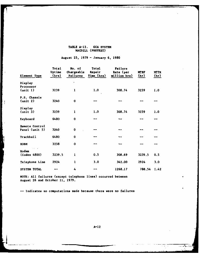
TABLE A-12. GCA SYSTEMMACDILL (PRETEST)
August 25, 1979 - January 6, 1980
Total No. of Total FailureUptime Chargeable Repair Rate (per MTBF MTTR
Element Type (hrs) Failures Time (hra) million hrs) (hr) (hr)
DisplayProcessor(unit 1) 3239 1 1.0 308.74 3239 1.0
P.S. Chassis
(unit 2) 3240 0 -- -- -- --
Display(unit 3) 3239 1 1.0 308.74 3239 1.0
Keyboard 6480 0 -- -- -- --
Remote ControlPanel (unit 5) 3240 0 ...... ..
Trackball 6480 0
RDBM 3238 0 -- -- -- --
Modem(Codex 4800) 3239.5 1 0.5 308.69 3239.5 0.5
Telephone Line 2924 1 3.0 342.00 2924 3.0
SYSTEM TOTAL -- 4 -- 1268.17 788.54 1.42
NOTE: All failures (except telephone lines) occurred betweenAugust 26 and October 11, 1979.
-- Indicates no computations made because there were no failures
A-12
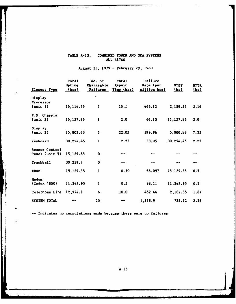
TABLE A-13. COMBINED TOWER AND GCA SYSTEMSALL SITES
August 25, 1979 - February 29, 1980
Total No. of Total FailureUptime Chargeable Repair Rate (per MTBF MTTR
Element Type (hra) Failures Time (hrs) million hr.) (hr) (hr)
DisplayProcessor(unit 1) 15,114.75 7 15.1 463.12 2,159.25 2.16
P.S. Chassis(unit 2) 15,127.85 1 2.0 66.10 15,127.85 2.0
Display
(unit 3) 15,002.63 3 22.05 199.96 5,000.88 7.35
Keyboard 30,254.45 1 2.25 33.05 30,254.45 2.25
Remote ControlPanel (unit 5) 15,129.85 0 -- -- -- --
Trackball 30,259.7 0 -- -- -- --
RDBM 15,129.35 1 0.50 66.097 15,129.35 0.5
Modem(Codex 4800) 11,348.95 1 0.5 88.11 11,348.95 0.5
Telephone Line 12,974.1 6 10.0 462.46 2,162.35 1.67
SYSTEM TOTAL -- 20 -- 1,378.9 725.22 2.56
-- Indicates no computations made because there were no failures
A-13
____ ____ ____ ___
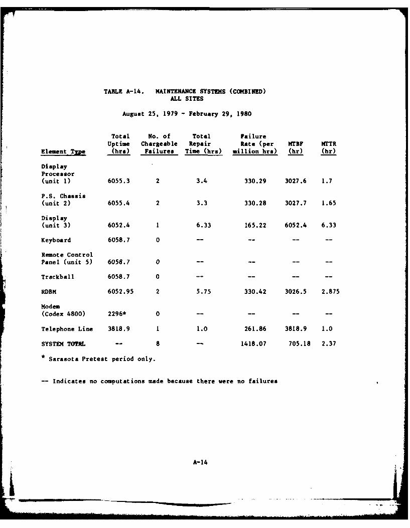
TABLE A-14. MAINTENANCE SYSTEMS (CONBINED)ALL SITES
August 25, 1979 - February 29, 1980
Total No. of Total FailureUptime Chargeable Repair Rate (per MTBF MTTR
Element Type (hrs) Failures Time (hrs) million hrs) (hr) (hr)
DisplayProcessor(unit 1) 6055.3 2 3.4 330.29 3027.6 1.7
P.S. Chassis(unit 2) 6055.4 2 3.3 330.28 3027.7 1.65
Display
(unit 3) 6052.4 1 6.33 165.22 6052.4 6.33
Keyboard 6058.7 0 -- -- -- --
Remote ControlPanel (unit 5) 6058.7 0 ........
Trackball 6058.7 0 -- -- -- --
RDBM 6052.95 2 5.75 330.42 3026.5 2.875
Modem(Codex 4800) 2296* 0 -- -- -- --
Telephone Line 3818.9 1 1.0 261.86 3818.9 1.0
SYSTEM TOTAL -- 8 -- 1418.07 705.18 2.37
* Sarasota Pretest period only.
-- Indicates no computations made because there were no failures
A-14
![[organization name] MTBF and MTTR Downtime Dashboard KPI … · 2017. 10. 15. · [organization name] MTBF and MTTR Downtime Dashboard KPI MTBF MTBF Nov Corrective action ID ATI)](https://img.pdfslide.net/doc/110x75/610e0b6c168138163b1c1b7f/organization-name-mtbf-and-mttr-downtime-dashboard-kpi-2017-10-15-organization.jpg)


![Linear actuators ATL Series and BSA Series - … · 42 2 2.2 TECHNICAL DATA - acme screw linear actuators ATL Series SIZE ATL 20 ATL 25 ATL 28 ATL 30 ATL 40 Push rod diameter [mm]](https://img.pdfslide.net/doc/110x75/5b5e55147f8b9a8b4a8c1cc7/linear-actuators-atl-series-and-bsa-series-42-2-22-technical-data-acme.jpg)