Embed Size (px)
Citation preview
St John the Evangelist
Catholic Church
Adoration Chapel Addition
Project Manual
Construction Documents
January 2013 T U R E
B A S 1 S A R C H I T E C T U R E P. C.

St John the Evangelist, Loveland, CO Adoration Chapel Addition
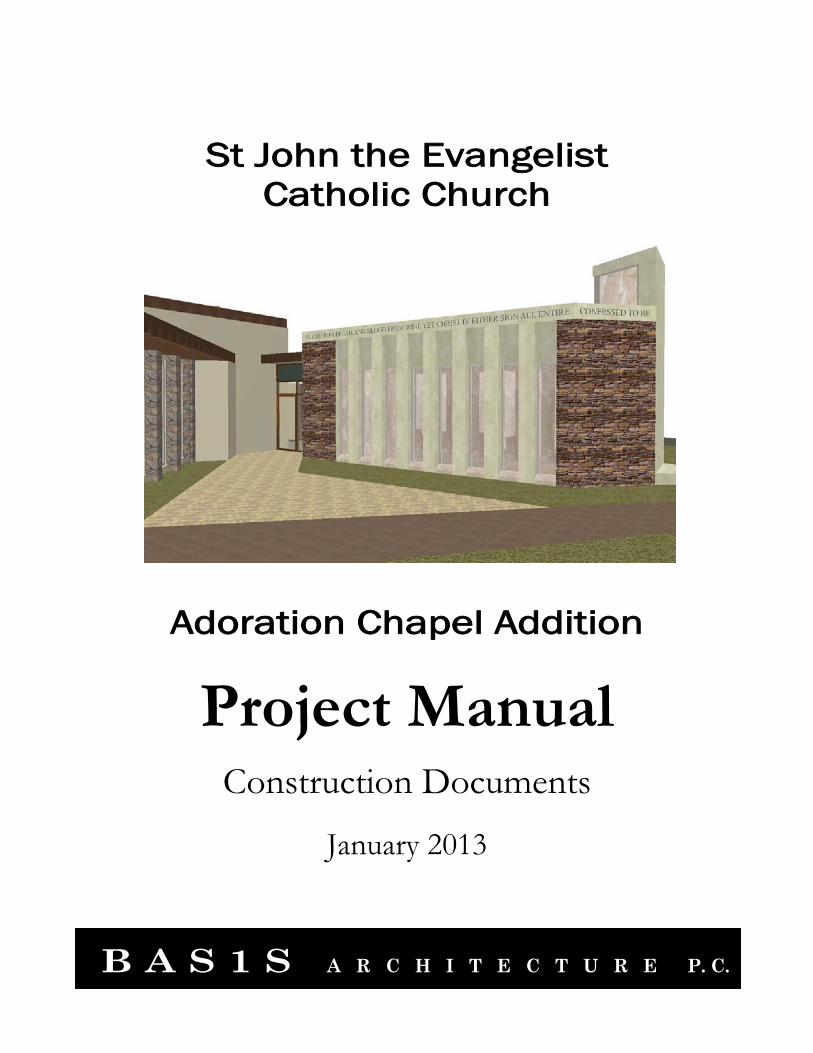
TABLE OF CONTENTS
SECTION SECTION NUMBER TITLE
January 2013 TOC-1 Table of Contents
DIVISION 00 - PROCUREMENT AND CONTRACTING REQUIREMENTS
00 0500 Agreement 00 3132 Geotechnical Data 00 7200 General Conditions
DIVISION 01 - GENERAL REQUIREMENTS 01 1100 Summary of Work 01 2300 Alternates 01 2500 Substitution Procedures 01 2600 Contract Modification Procedures 01 2900 Payment Procedures 01 3100 Project Management and Coordination 01 3300 Submittal Procedures 01 4000 Quality Requirements 01 4523 Testing and Inspection Services 01 5000 Temporary Facilities and Controls 01 6000 Product Requirements 01 7329 Cutting and Patching 01 7700 Closeout Procedures DIVISION 03 - CONCRETE 03 1000 Concrete Forming 03 2000 Concrete Reinforcing 03 3000 Cast-in-Place Concrete 03 3500 Concrete Finishing DIVISION 04 - MASONRY 04 0513 Masonry Mortar and Grout 04 2000 Unit Masonry 04 4000 Stone Assemblies 04 7300 Natural Thin Stone Veneer DIVISION 05 - METALS 05 1200 Structural Steel Framing 05 2100 Steel Joist Framing 05 3123 Steel Roof Decking 05 5000 Metal Fabrications DIVISION 06 - WOOD, PLASTICS AND COMPOSITES 06 4100 Architectural Wood Casework 06 4600 Wood Trim
St John the Evangelist, Loveland, CO Adoration Chapel Addition
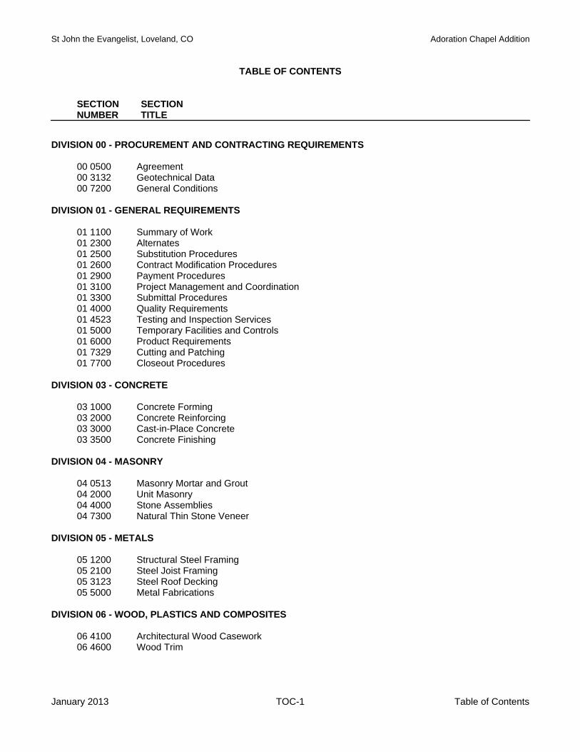
CONSOLIDATED TABLE OF CONTENTS
SECTION SECTION NUMBER TITLE
January 2013 TOC-2 Table of Contents
DIVISION 07 - THERMAL AND MOISTURE PROTECTION 07 1113 Dampproofing 07 2113 Board Insulation 07 2119 Foamed-In-Place Insulation 07 2123 Loose Fill Insulation 07 5300 Elastomeric Membrane Roofing 07 6200 Sheet Metal Flashing and Trim 07 9200 Joint Sealers DIVISION 08 - OPENINGS 08 1416 Flush Wood Doors 08 1433 Stile and Rail Wood Doors 08 3100 Access Doors and Panels 08 4113 Aluminum-Framed Entrances and Storefronts 08 7100 Door Hardware 08 8000 Glazing DIVISION 09 - FINISHES 09 2200 Metal Support Assemblies 09 2400 Portland Cement Plastering 09 2900 Gypsum Board 09 3000 Tiling 09 5100 Acoustical Ceilings 09 6400 Wood Flooring 09 7500 Stone Wall Facings 09 9100 Painting DIVISION 10 - SPECIALTIES 10 1423 Interior Panel Signs 10 2813 Toilet Accessories DIVISION 11 – EQUIPMENT – Not Used DIVISION 12 – FURNISHINGS – Not Used DIVISION 13 - SPECIAL CONSTRUCTION – Not Used
DIVISION 14 - CONVEYING EQUIPMENT – Not Used DIVISION 15 - MECHANICAL – See Drawings
St John the Evangelist, Loveland, CO Adoration Chapel Addition
CONSOLIDATED TABLE OF CONTENTS
SECTION SECTION NUMBER TITLE
January 2013 TOC-3 Table of Contents
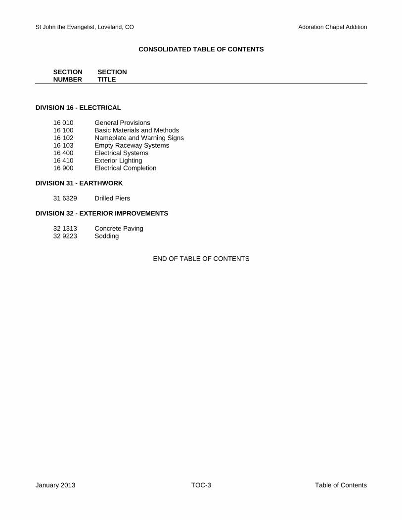
DIVISION 16 - ELECTRICAL 16 010 General Provisions 16 100 Basic Materials and Methods 16 102 Nameplate and Warning Signs 16 103 Empty Raceway Systems 16 400 Electrical Systems 16 410 Exterior Lighting 16 900 Electrical Completion DIVISION 31 - EARTHWORK 31 6329 Drilled Piers DIVISION 32 - EXTERIOR IMPROVEMENTS 32 1313 Concrete Paving 32 9223 Sodding
END OF TABLE OF CONTENTS

St John the Evangelist, Loveland, CO Adoration Chapel Addition
January 2013 00 0500-1 Agreement
DOCUMENT 00 0500
AGREEMENT 1.1 SUMMARY
A. Related Documents: 1. Document 00 7200 - General Conditions. 2. Division 01 - General Requirements.
1.2 DOCUMENT
A. American Institute of Architects (AIA) Document A120-2007, Standard Form of Agreement between Owner and Contractor, where the basis of payment is the Cost of the Work, plus a Fee, with a Guaranteed Maximum Price, as modified by the Archdiocese of Denver, shall be the form of Agreement and by reference is incorporated herein as fully as if repeated at length.
END OF DOCUMENT
St John the Evangelist, Loveland, CO Adoration Chapel Addition
January 2013 00 3132-1 Geotechnical Data
DOCUMENT 00 3132
GEOTECHNICAL DATA 1.1 INVESTIGATION
A. Geotechnical investigations were conducted at the site, the results of which can be found in the report issued by CDS Engineering, Report No. 12-6107 dated.
B. A copy of the report is available upon request to the Architect.
1.2 INTERPRETATION
A. The report is provided only for bidder's information and convenience and is not part of the Contract Documents. Owner and Architect do not warrant the accuracy or extent of the report or locations of the test borings.
B. The report is based upon the assumption that uniform variation exists in soil properties between
borings. Interpretation of the report is bidder's responsibility. Owner and Architect will not be responsible for interpretation of report by bidders.
C. Bidders are urged to examine the report and the site. D. Additional soil borings or other exploratory operations may be made by bidders at no additional cost
to Owner, provided such operations are approved by Owner in advance. E. Refer to Conditions of the Contract for additional information.
END OF DOCUMENT
St John the Evangelist, Loveland, CO Adoration Chapel Addition
January 2013 00 7200-1 General Conditions
DOCUMENT 00 7200
GENERAL CONDITIONS 1.1 SUMMARY
A. Related Documents: 1. Division 01 - General Requirements.
1.2 DOCUMENT
A. American Institute of Architects (AIA) Document A201-2007, General Conditions of the Contract for Construction, as modified by the Archdiocese of Denver, forms a part of this Contract and by reference is incorporated herein as fully as if repeated at length.
END OF DOCUMENT

St John the Evangelist, Loveland, CO Adoration Chapel Addition
January 2013 01 1100-1 Summary of Work
SECTION 01 1100
SUMMARY OF WORK PART 1GENERAL 1.1 SUMMARY
A. Section Includes: 1. Project description. 2. Work by Others. 3. Work sequence. 4. Owner occupancy. 5. Contractor’s use of site and premises. 6. Owner furnished Products.
1.2 PROJECT DESCRIPTION
A. Work of this Project is described as the construction of a new one-story addition to an existing facility entitled St John the Evangelist Catholic Church, located at 1730 W. 12th Street, Loveland, Colorado.
B. Work includes site construction, general construction, fire protection, plumbing, HVAC, and electrical.
C. The Project will be constructed under a single prime contract. 1.3 WORK BY OTHERS
A. Work by Owner: The following portions of the work are to be provided by the Owner and/or a Contractor under separate agreement with the Owner. 1. Etching of interior marble (marble to be supplied and installed by GC) 2. Etching of interior glass at chapel door (glass to be supplied and installed by GC) 3. Stained glass windows. 4. Mosaic or hammered metal wall finish at south wall of chapel. 5. Security systems, including entry door ‘keypad’ (rough-in to be furnished and installed by GC)
1.4 OWNER OCCUPANCY
A. The Owner will occupy the site and adjacent premises during the entire period of construction for conduct of normal operations.
B. Cooperate with the Owner to minimize conflict, and to facilitate Owner’s operations.
C. Schedule the Work to accommodate this requirement.
1.5 CONTRACTOR’S USE OF SITE AND PREMISES
A. Limit use of site and premises to allow for: 1. Owner occupancy.
B. Move any stored products under Contractor’s control that interfere with the operations of the Owner.
C. Assume full responsibility for protection and safekeeping of products under this Contract stored on
site.

St John the Evangelist, Loveland, CO Adoration Chapel Addition
January 2013 01 1100-2 Summary of Work
D. Obtain and pay for use of any additional storage or work areas needed for operations.
E. Coordinate use of site and premises with the Owner: 1. Employee parking: 2. Access to site: 3. Storage and staging areas:
F. Confine operations to construction area unless otherwise approved by Owner.
G. If access to adjacent common or occupied spaces is required:
1. Schedule operations with Owner in advance.
H. Do not interrupt building fire or life safety systems.
I. Do not close or obstruct exits.
J. Do not use or store hazardous or flammable materials on premises without Owner’s approval; follow requirements of governing authorities having jurisdiction over the work.
K. Prohibit smoking within interior spaces.
1.6 WORK BY OWNER TO BE INCORPORATED INTO PROJECT BY CONTRACTOR
A. Owner's Responsibilities: 1. Arrange for and deliver necessary Shop Drawings, Product Data and Samples to Contractor. 2. Arrange and pay for product delivery to site, in accordance with Progress Schedule. 3. Deliver supplier's bill of materials to Contractor. 4. Inspect deliveries jointly with Contractor. 5. Submit claims for transportation damage. 6. Arrange for replacement of damaged, defective, and missing items. 7. Arrange for manufacturers' warranties, service, and inspections, as required.
B. Contractor’s Responsibilities:
1. Designate delivery date for each product in Progress Schedule. 2. Review Shop Drawings, Product Data and Samples. Submit to Architect with notification of any
discrepancies or problems anticipated in use of product. 3. Receive and unload products at site. 4. Promptly inspect products jointly with Owner; record shortages, damage, and defective items. 5. Handle products at site, including uncrating and storage. 6. Protect products from exposure to elements and from damage. 7. Assemble, install, connect, adjust, and finish products, as stipulated in respective specification
section. 8. Repair or replace any items damaged by Contractor.
PART 2 PRODUCTS
Not used PART 3 EXECUTION
Not used
END OF SECTION
St John the Evangelist, Loveland, CO Adoration Chapel Addition
January 2013 01 2300-1 Alternates
SECTION 01 2300
ALTERNATES PART 1 GENERAL 1.1 SUMMARY
A. Section Includes 1. Documentation of changes to Contract Sum and Contract Time.
B. Contract Documents contain pertinent requirements for materials and methods to accomplish work
described herein.
C. Provide alternate costs for inclusion in Contract Sum if accepted by Owner. 1.2 RELATED REQUIREMENTS
A. Owner/Contractor Agreement: Alternates accepted by Owner for incorporation into the Work.
B. Individual specification sections identified. 1.3 PROCEDURES
A. Alternates will be exercised at the option of Owner.
B. Coordinate related work and modify surrounding work as required to complete the work, including changes under each Alternate, when acceptance is designated in Owner/Contractor Agreement.
1.4 DESCRIPTION OF ALTERNATES
A. Alternate No. 1 – Wood trim/Wood Flooring: 1. Base Bid: Provide Northern Hard Maple as specified in Section 06 4600 Wood Trim and
Section 09 6400 Wood Flooring for Chapel walls, ceilings and floors. 2. Alternate Bid: In lieu of Northern Hard Maple, provide Santos Mahogany.
B. Alternate No. 2 – EPDM Roofing
1. Base Bid: Provide Black EPDM roofing as specified in Section 07 5300. 2. Alternate Bid: In lieu of Black EPDM, provide White EPDM as specified in Section 07 5300.
C. Alternate No. 3 – Aluminum Entrance Door 1. Base Bid: Provide 7’-0” tall aluminum entrance door as indicated on Drawings and specified in
Section 08 4113. 2. Alternate Bid: In lieu of 7’-0” tall door, eliminate transom and provide 9’ high door.
D. Alternate No. 4 – Chapel Light Fixture
1. Base Bid: Provide recessed can fixture ‘A’ as scheduled. 2. Alternate Bid: Substitute scheduled fixture with Juno IC22LEDG3-3K-U-27C-BL.
E. Alternate No. 5 – Engraved Fascia 1. Base Bid: Provide Engraved Fascia as component of Precast Lintel with integral color to match
adjacent stone, as indicated on drawings. 2. Alternate Bid: Delete integral color and engraved fascia from Precast Lintel, add supports for
veneer stone fascia. Provide Engraved Fascia in stone facing as specified in Section 04 4000.

St John the Evangelist, Loveland, CO Adoration Chapel Addition
January 2013 01 2300-2 Alternates
PART 2 PRODUCTS – Not Used PART 3 EXECUTION – Not Used
END OF SECTION
St John the Evangelist, Loveland, CO Adoration Chapel Addition
January 2013 01 2500-1 Substitution Procedures
SECTION 01 2500
SUBSTITUTION PROCEDURES PART 1 GENERAL 1.1 SUMMARY
A. Section Includes: 1. Product Substitution Procedures.
1.2 GENERAL
A. Definition: Proposal by Contractor to use manufacturer, product, material, or system different from one required in Contract Documents.
B. Do not substitute Products unless a substitution request has been approved by Architect.
C. In case of non-availability of a specified Product notify Architect in writing as soon as non-availability
becomes apparent. 1.3 SUBSTITUTION REQUESTS
A. Submit substitution requests on Contractor’s standard form.
B. Document specified product and proposed substitution with complete data, including: 1. Product identification, including name and address of manufacturer. 2. Product description, performance and test data, and reference standards. 3. Sample, if requested. 4. Description of any anticipated effect that acceptance of proposed substitution will have on
Progress Schedule, construction methods, or other items of Work. 5. Description of any differences between specified product and proposed substitution. 6. Difference in cost between specified product and proposed substitution.
C. Burden of proof for substantiating compliance of proposed substitution with Contract Document
requirements remains with Contractor.
D. A request constitutes a representation that the Contractor: 1. Has investigated the proposed Product and determined that it meets or exceeds the quality
level of the specified Product. 2. Will provide the same warranty for the substitution as for the specified Product. 3. Will coordinate installation and make changes to other Work that may be required for the Work
to be complete with no additional cost to Owner. 4. Waives claims for additional costs or time extension that may subsequently become apparent. 5. Will reimburse Owner for design services associated with re-approval by authorities or revisions
to Contract Documents to accommodate the substitution.
E. Substitutions will not be considered if: 1. They are indicated or implied on Shop Drawings or other submittals without submittal of a
substitution request. 2. Approval will require substantial revision of Contract Documents without additional
compensation to Architect.
St John the Evangelist, Loveland, CO Adoration Chapel Addition
January 2013 01 2500-2 Substitution Procedures
F. Submit electronically in Adobe PDF format.
G. Architect will notify Contractor of approval or rejection of each Substitution Request. PART 2 PRODUCTS Not used PART 3 EXECUTION
Not used
END OF SECTION
St John the Evangelist, Loveland, CO Adoration Chapel Addition
January 2013 01 2600-1 Contract Modification Procedures
SECTION 01 2600
CONTRACT MODIFICATION PROCEDURES PART 1 GENERAL 1.1 SUMMARY
A. Section Includes: 1. Supplemental Instructions. 2. Proposal Requests. 3. Contractor proposed changes. 4. Construction Change Directives. 5. Change Orders.
B. Related Sections:
1. Section 01 6000 - Product Requirements. 1.2 CHANGE PROCEDURES
A. Architect's Supplemental Instructions: 1. Architect will advise of minor changes in Work not involving an adjustment to Contract Sum or
Contract Time as authorized by the Conditions of the Contract.
B. Proposal Requests: 1. Architect may issue a Proposal Request that includes a detailed description of a proposed
change with supplemental or revised Drawings and specifications. 2. Prepare and submit an estimate of any change to Contract Sum or Contract Time within [7]
days after receipt. Include: a. Quantities and unit costs, with total cost or credit to Owner. If requested, furnish
documentation of quantities. b. Taxes, delivery charges, equipment rentals, and trade discounts as applicable. c. If change in Contract Time is involved, provide updated Progress Schedule.
3. Do not stop work or initiate changes in response to a Proposal Request. If approved, Architect will prepare and issue a Change Order.
4. Submit electronically in Adobe PDF format.
C. Contractor Proposed Changes: 1. Format: Contractor’s standard. 2. Contractor may propose a change by submitting request for change to Architect. 3. Describe proposed change, reason for change, its full effect on Work, and any change to
Contract Sum or Contract Time. Include: a. Quantities and unit costs, with total cost or credit to Owner. If requested, furnish
documentation of quantities. b. Taxes, delivery charges, equipment rentals, and trade discounts as applicable. c. If change in Contract Time is involved, provide updated Progress Schedule.
4. Document any required substitutions in accordance with Section 01 6000. 5. Submit electronically in Adobe PDF format.
D. Construction Change Directive:
1. Architect may issue a directive, signed by Owner, instructing Contractor to proceed with a change for subsequent inclusion in a Change Order.
2. Documentation will describe changes in Work and designate method of determining any change to Contract Sum or Contract Time. Promptly execute change.
St John the Evangelist, Loveland, CO Adoration Chapel Addition
January 2013 01 2600-2 Contract Modification Procedures
E. Change Orders:
1. Format: AIA Document G701 - Change Order. 2. Execution: Change Orders for signature of parties will be issued as provided in Conditions of
the Contract. PART 2 PRODUCTS Not used PART 3 EXECUTION Not used
END OF SECTION

St John the Evangelist, Loveland, CO Adoration Chapel Addition
January 2013 01 2900-1 Payment Procedures
SECTION 01 2900
PAYMENT PROCEDURES PART 1 GENERAL 1.1 SUMMARY
A. Section Includes: 1. Schedule of Values. 2. Applications for Payment.
B. Related Sections:
1. Section 01 7700 - Closeout Procedures. 1.2 SCHEDULE OF VALUES
A. General: 1. Submit a Schedule of Values to Architect at least [20] days prior to submitting first Application
for Payment. 2. Upon request of Architect, furnish additional data to support values given that will substantiate
their correctness. 3. Approved Schedule of Values will be used as basis for reviewing Contractor’s Applications for
Payment.
B. Form and Content: 1. Format: AIA Document G703 - Continuation Sheet of Application and Certification for Payment.
Use Table of Contents of Project Manual as basis of format for listing costs of Work. 2. List installed value of component parts of Work in sufficient detail to serve as basis for
computing values for progress payments. 3. Include separate line items for:
a. Site mobilization. b. [Bonds and] insurance. c. Contractor’s overhead and profit.
4. For items on which payment will be requested for stored materials, break down value into: a. Cost of materials, delivered and unloaded. b. Total installed value.
5. For each line item that has a value of more than [$25,000.00,] break down costs to list major products or operations under each item.
6. Total of costs listed in Schedule shall equal Contract Sum.
C. Submit three copies.
D. Review and Resubmittal: 1. After initial review by Architect, revise and resubmit if required. 2. Revise and resubmit along with next Application for Payment when a Change Order is issued.
List each Change Order as a new line item. 1.3 APPLICATIONS FOR PAYMENT
A. Preparation: 1. Format: AIA Document G702 - Application and Certification for Payment, supported by AIA
Document G703 - Continuation Sheet. 2. Prepare required information in typewritten format or on electronic media format.
St John the Evangelist, Loveland, CO Adoration Chapel Addition
January 2013 01 2900-2 Payment Procedures
3. Use data from reviewed Schedule of Values. Provide dollar value in each column for each line item representing portion of work performed.
4. List each authorized Change Order as a separate line item, listing Change Order number and dollar value.
5. Prepare Application for Final Payment as specified in Section 01 7700.
B. Waivers of Lien: 1. Along with the each Application for Payment, submit waivers of lien from Contractor and each
Subcontractor or Sub-subcontractor included on the previous month's Application for Payment. 2. Submit partial waivers on each item for amount requested, prior to deduction of retainage. 3. For completed items, submit full or final waiver.
C. Substantiating Data:
1. When Architect requires substantiating information, submit data justifying dollar amounts in question.
2. Provide one copy of data with cover letter showing Application number and date, and line item number and description.
D. Submittal:
1. Submit three copies of each Application for Payment. 2. Payment period: Submit at intervals stipulated in Owner/Contractor Agreement.
PART 2 PRODUCTS
Not used PART 3 EXECUTION
Not used
END OF SECTION
St John the Evangelist, Loveland, CO Adoration Chapel Addition
January 2013 01 3100-1 Project Management and Coordination
SECTION 01 3100
PROJECT MANAGEMENT AND COORDINATION PART 1 GENERAL 1.1 SUMMARY
A. Section Includes: 1. Project coordination. 2. Coordination drawings. 3. Project meetings.
B. Related Sections:
1. Section 01 7700 - Contract Closeout. 1.2 PROJECT COORDINATION
A. Submit required project submittals electronically in Abode PDF format.
B. Coordinate scheduling, submittals, and work of various Sections of specifications to assure efficient and orderly sequence of installation of interdependent construction elements.
C. Verify that utility requirement characteristics of operating equipment are compatible with building
utilities. Coordinate work of various Sections having interdependent responsibilities for installing, connecting to, and placing in service such equipment.
D. Coordinate space requirements and installation of mechanical and electrical items that are indicated
diagrammatically on Drawings. 1. Follow routing shown as closely as practical; place runs parallel with building lines. 2. Utilize spaces efficiently to maximize accessibility for other installations, for maintenance, and
for repairs.
E. In finished areas, conceal pipes, ducts, and wiring within construction. Coordinate locations of fixtures and outlets with finish elements.
F. Coordinate completion and clean up of work of separate Sections in preparation for Substantial
Completion.
G. After Owner occupancy, coordinate access to site for correction of defective Work and Work not in accordance with Contract Documents to minimize disruption of Owner's activities.
1.3 PROJECT MEETINGS
A. Schedule and administer preconstruction conference, progress meetings and pre-installation conferences.
B. Make physical arrangements for meetings; notify involved parties at least [7] days in advance.
C. Record significant proceedings and decisions at each meeting; reproduce and distribute copies to
parties in attendance and others affected by proceedings and decisions made.

St John the Evangelist, Loveland, CO Adoration Chapel Addition
January 2013 01 3100-2 Project Management and Coordination
1.4 PRECONSTRUCTION CONFERENCE
A. Schedule within [15] days after date of Notice to Proceed at site.
B. Attendance: 1. Contractor. 2. Owner. 3. Architect.
C. Review and Discuss:
1. Relation and coordination of various parties, and responsible personnel for each party. 2. Use of premises, including office and storage areas, temporary controls, and security
procedures. 3. Construction schedule and critical work sequencing. 4. Processing of:
a. Contract modifications. b. Shop Drawings, Product Data, and Samples. c. Applications for Payment. d. Substitutions. e. Requests for Information. f. Other required submittals.
5. Adequacy of distribution of Contract Documents. 6. Procedures for maintaining contract closeout submittals. 7. Installation and removal of temporary facilities. 8. Notification procedures and extent of testing and inspection services.
1.5 PROGRESS MEETINGS
A. Schedule progress meetings at two-week intervals and/or as necessary to follow the progress of the Work.
B. Location: Project field office.
C. Attendance:
1. Contractor. 2. Owner. 3. Architect and consultants as appropriate to agenda. 4. Subcontractors and suppliers as appropriate to agenda. 5. Others as appropriate to agenda.
D. Review and Discuss:
1. Work progress since previous meeting, including: a. Field observations, deficiencies, conflicts, and problems. b. Progress and completion date. c. Corrective measures needed to maintain quality standards, progress, and completion
date. 2. Status of:
a. Requests for information. b. Submittals. c. Contract modifications.
3. Coordination between various elements of Work. 4. Maintenance of Project Record Documents.
St John the Evangelist, Loveland, CO Adoration Chapel Addition
January 2013 01 3100-3 Project Management and Coordination
1.6 PRE-INSTALLATION CONFERENCES
A. Where required in individual specification Section, convene a pre-installation conference at project site or other designated location.
B. Require attendance of parties directly affecting or affected by work of the specific Section.
C. Review conditions of installation, preparation and installation procedures, and coordination with
related work. PART 2 PRODUCTS Not used PART 3 EXECUTION Not used
END OF SECTION
St John the Evangelist, Loveland, CO Adoration Chapel Addition
January 2013 01 3300-1 Submittal Procedures
SECTION 01 3300
SUBMITTAL PROCEDURES PART 1 GENERAL 1.1 SUMMARY
A. Section Includes: 1. Submittal procedures. 2. Proposed Products list. 3. Submittal schedule. 4. Shop Drawings. 5. Product Data. 6. Samples. 7. Quality control submittals.
B. Related Sections:
1. Section 01 4000 - Quality Requirements. 1.2 SUBMITTAL PROCEDURES
A. Number each submittal with Project Manual section number and a sequential number within each section. Number resubmittals with original number and an alphabetic suffix.
B. Identify Project, Contractor, Subcontractor or supplier, pertinent Drawing sheet and detail numbers,
and specification Section number, as appropriate.
C. Submit all submittals listed under “Submittals for Review” simultaneously for each Product or Specification Section.
D. Where multiple Products function as an assembly, group submittals for all related Products into single
submittal.
E. Architect will not review incomplete submittals.
F. Apply Contractor’s stamp, signed or initialed certifying that: 1. Submittal was reviewed. 2. Products, field dimensions, and adjacent construction have been verified. 3. Information has been coordinated with requirements of Work and Contract Documents.
G. Schedule submittals to expedite the Project, and deliver to Architect. Coordinate submittal of related
items.
H. For each submittal, allow [10] business days for Architect’s review, excluding delivery time to and from Contractor.
I. Identify variations from Contract Documents and Product or system limitations that may be
detrimental to successful performance of completed Work.
J. Revise and resubmit submittals when required; identify all changes made since previous submittal.
K. Distribute copies of reviewed submittals to concerned parties and to Project Record Documents file. Instruct parties to promptly report any inability to comply with provisions.
St John the Evangelist, Loveland, CO Adoration Chapel Addition
January 2013 01 3300-2 Submittal Procedures
1.3 SUBMITTAL SCHEDULE
A. Within [15] days after date of Notice to Proceed, submit a submittal schedule showing all submittals proposed for project, including submittals listed as: 1. Submittals for Review. 2. Quality Control Submittals. 3. Closeout Submittals.
B. Include for each submittal:
1. Specification section number. 2. Description of submittal. 3. Type of submittal. 4. Anticipated submittal date.
C. Submit electronically in Adobe PDF format.
1.4 SHOP DRAWINGS
A. Present information in clear and thorough manner.
B. Identify details by reference to sheet and detail numbers or room number shown on Drawings.
C. Reproductions of details contained in Contract Documents are not acceptable.
D. Submit electronically in Adobe PDF format. Architect will return one copy to Contractor for printing and distribution.
1.5 PRODUCT DATA
A. Mark each copy to identify applicable products, models, options, and other data.
B. Supplement manufacturers' standard data to provide information unique to this Project.
C. Submit electronically in Adobe PDF format. Architect will return one copy to Contractor for printing and distribution.
1.6 SAMPLES
A. Submit samples to illustrate functional and aesthetic characteristics of Products, with integral parts and attachment devices. Coordinate sample submittals for interfacing work.
B. Where so indicated, submit samples of finishes from the full range of manufacturers' standard colors,
textures, and patterns for Architect's selection.
C. Include identification on each sample, with full Project information.
D. Unless otherwise specified in individual specifications, submit one of each sample.
E. Architect will notify Contractor of approval or rejection of samples, or of selection of color, texture, or pattern if full range is submitted.
St John the Evangelist, Loveland, CO Adoration Chapel Addition
January 2013 01 3300-3 Submittal Procedures
1.7 QUALITY CONTROL SUBMITTALS
A. Quality control submittals specified in Section 01 4000 are for information and do not require Architect’s responsive action except to require resubmission of incomplete or incorrect information.
PART 2 PRODUCTS Not used PART 3 EXECUTION
Not used
END OF SECTION
St John the Evangelist, Loveland, CO Adoration Chapel Addition
January 2013 01 4000-1 Quality Requirements
SECTION 01 4000
QUALITY REQUIREMENTS PART 1 GENERAL 1.1 SUMMARY
A. Section Includes: 1. References. 2. Quality assurance and control of installation. 3. Manufacturer's field services and reports. 4. Design data and calculations. 5. Test reports and certifications. 6. Manufacturer's installation instructions.
1.2 REFERENCES
A. For products or workmanship specified by reference to association, trade, or industry standards, comply with requirements of the standard, except when more rigid requirements are specified or are required by applicable codes.
B. Should specified reference standards conflict with Contract Documents, request clarification from
Architect before proceeding.
C. Conform to edition of reference standard in effect as of date of Owner/Contractor Agreement.
D. The contractual relationship of the parties to the Contract shall not be altered from the Contract Documents by mention or inference otherwise in any reference document.
1.3 QUALITY ASSURANCE AND CONTROL OF INSTALLATION
A. Monitor quality control over suppliers, manufacturers, Products, services, site conditions, and workmanship, to produce Work of specified quality.
B. Comply fully with manufacturers' instructions, including each step in sequence.
C. Should manufacturers' instructions conflict with Contract Documents, request clarification from
Architect before proceeding.
D. Comply with specified standards as a minimum quality for the Work except when more stringent tolerances, codes, or specified requirements indicate higher standards or more precise workmanship.
E. Perform work by persons qualified to produce workmanship of specified quality.
F. Secure Products in place with positive anchorage devices designed and sized to withstand stresses,
vibration, physical distortion or disfigurement. 1.4 MANUFACTURERS' FIELD SERVICES AND REPORTS
A. When specified in individual specification Sections, require material or Product suppliers or manufacturers to provide qualified staff personnel to observe site conditions, conditions of surfaces and installation, quality of workmanship, or startup of equipment, as applicable, and to initiate instructions when necessary.
St John the Evangelist, Loveland, CO Adoration Chapel Addition
January 2013 01 4000-2 Quality Requirements
B. Individuals to report observations and site decisions or instructions given to applicators or installers
that are supplemental or contrary to manufacturers' written instructions.
C. Submit report to Architect within [10] days of observation. 1.5 DESIGN DATA AND CALCULATIONS
A. When specified in individual specification Sections, require material or Product suppliers or manufacturers to provide design data and calculations.
B. Accuracy of design data and calculations is the responsibility of the Contractor.
C. When so specified, prepare design data and calculations under the direction of a professional
engineer licensed in the state in which the Project is located. Affix engineer’s seal to submittals.
D. Submit electronically in Adobe PDF format. 1.6 TEST REPORTS AND CERTIFICATIONS
A. When specified in individual specification Sections, require material or Product suppliers or manufacturers to provide test reports and manufacturers’ certifications.
B. Indicate that material or Product conforms to or exceeds specified requirements. Submit supporting
reference data, affidavits, and certifications as appropriate.
C. Submittals may be recent or previous test results on material or Product, but must be acceptable to Architect.
D. Submit electronically in Adobe PDF format.
1.7 MANUFACTURER'S INSTALLATION INSTRUCTIONS
A. When Contract Documents require that Products be installed in accordance with manufacturer's instructions: 1. Submit manufacturer's most recent printed instructions for delivery, storage, assembly,
installation, start-up, adjusting, and finishing, as applicable. a. Submit in quantities specified for Product Data. b. Indicate special procedures, perimeter conditions requiring special attention, and special
environmental criteria required for application or installation. c. Identify conflicts between manufacturers' instructions and requirements of Contract
Documents. 2. Perform installation of Products to comply with requirements of manufacturer's instructions. 3. If installation cannot be performed in accordance with manufacturer's instructions, notify
Architect and await instructions. 4. Submit electronically in Adobe PDF format.
PART 2 PRODUCTS – Not Used PART 3 EXECUTION – Not Used
END OF SECTION
St John the Evangelist, Loveland, CO Adoration Chapel Addition
January 2013 01 4523-1 Testing and Inspection Services
SECTION 01 4523
TESTING AND INSPECTION SERVICES PART 1 GENERAL 1.1 SUMMARY
A. Section Includes: 1. Laboratory selection and payment. 2. Laboratory duties. 3. Contractor’s responsibilities.
B. Related Sections: Individual specifications sections contain specific tests and inspections to be
performed. 1.2 REFERENCES
A. ASTM International (ASTM): 1. C1077 - Standard Practice for Laboratories Testing Concrete and Concrete Aggregates for Use
in Construction and Criteria for Laboratory Evaluation. 2. D3666 - Standard Specification for Minimum Requirements for Agencies Testing and Inspecting
Road and Paving Materials. 3. D3740 - Standard Practice for Minimum Requirements for Agencies Engaged in the Testing
and/or Inspection of Soil and Rock as Used in Engineering Design and Construction. 4. E329 - Standard Specification for Agencies Engaged in Construction Inspection and/or Testing. 5. E543 - Standard Specification for Agencies Performing Nondestructive Testing.
1.3 QUALITY ASSURANCE
A. Owner will employ and pay for services of an independent testing laboratory to perform specified testing and inspection.
B. Contractor] shall cooperate with the Testing Laboratory to facilitate performance of its work.
C. Refer to the Conditions of the Contract for provisions related to special inspections and testing.
D. Qualifications of Laboratory:
1. Meet requirements of ASTM [C1077] [D3666] [D3740] [E329] [and] [E543]. 2. Authorized to operate in State in which project is located.
1.4 LABORATORY DUTIES
A. Cooperate with Architect and Contractor; provide qualified personnel after due notice.
B. Perform specified inspections, sampling, and testing of materials and methods of construction: 1. Comply with specified standards. 2. Ascertain compliance or noncompliance of materials with requirements of Contract Documents.
C. Promptly notify Architect and Contractor of observed irregularities or deficiencies of Work or products.
D. Promptly submit written report of each test and inspection; submit electronically in Adobe PDF format
to Architect and Contractor.
St John the Evangelist, Loveland, CO Adoration Chapel Addition
January 2013 01 4523-2 Testing and Inspection Services
E. Each report to include:
1. Date issued. 2. Project title and number. 3. Testing Laboratory name, address, and telephone number. 4. Name of Inspector and signature of individual in charge. 5. Date and time of sampling or inspection. 6. Record of temperature and weather conditions. 7. Date of test. 8. Identification of product and specification section. 9. Location of sample or test in project. 10. Type of inspection or test. 11. Results of tests and compliance or noncompliance with Contract Documents.
F. Perform additional tests when required by Architect or Contractor.
G. Laboratory is not authorized to:
1. Release, revoke, alter, or enlarge on requirements of Contract Documents. 2. Approve or accept any portion of work. 3. Perform any duties of Contractor.
1.5 CONTRACTOR’S RESPONSIBILITIES
A. Cooperate with Laboratory personnel, provide access to Work, and to manufacturer's operations.
B. When materials require testing prior to being incorporated into Work, secure and deliver to Laboratory adequate quantities of representative samples of materials proposed to be used.
C. Furnish copies of product test reports as required.
D. Furnish incidental labor and facilities:
1. To provide access to work to be tested. 2. To obtain and handle samples at site or at source of product to be tested. 3. To facilitate inspections and tests. 4. For safe storage and curing of test samples.
E. Notify Laboratory sufficiently in advance of operations to allow for Laboratory assignment of
personnel and scheduling of tests.
F. When tests or inspections cannot be performed after such notice, reimburse Owner for Laboratory personnel and travel expenses incurred due to Contractor’s negligence.
G. Make arrangements with Laboratory and pay for additional samples and tests required for
Contractor’s convenience or findings of noncompliance with Contract Documents. PART 2 PRODUCTS Not used
St John the Evangelist, Loveland, CO Adoration Chapel Addition
January 2013 01 4523-3 Testing and Inspection Services
PART 3 EXECUTION 3.1 TESTING AND INSPECTION SCHEDULE
A. Cast in Place Concrete - Section 03 3000: As noted in section.
B. Load-Bearing Masonry Construction - Section 04 2000: 1. Masonry construction:
a. Verify dimensions and condition of grout spaces and type, quantity, and placement of reinforcement during installation and just prior to closing of cleanouts.
b. Verify type, quantity, and installation of reinforcement, anchors, and ties. c. Inspect placement of grout.
END OF SECTION
St John the Evangelist, Loveland, CO Adoration Chapel Addition
January 2013 01 5000-1 Temporary Facilities and Controls
SECTION 01 5000
TEMPORARY FACILITIES AND CONTROLS PART 1 GENERAL 1.1 SUMMARY
A. Section Includes: 1. Temporary utilities. 2. Field offices and sheds. 3. Temporary controls. 4. Protection of installed Work. 5. Security. 6. Progress cleaning. 7. Water, erosion, sediment, dust, and mold and mildew control. 8. Access roads and parking areas. 9. Removal.
PART 2 PRODUCTS Not used PART 3 EXECUTION 3.1 TEMPORARY ELECTRICITY
A. Provide temporary electrical service of capacity and characteristics required for construction.
B. Connect to existing electrical system for electricity required during construction. 1. Cost of electricity used will be paid for by Owner. Exercise measures to conserve electricity. 2. Regulate system to prevent interference with Owner's normal usage. 3. Maintain continuous power operation of Owner's facilities during changeover of electrical
services. 4. Notify Owner when unusually heavy loads will be connected, including welding and other
equipment with special power requirements. 5. Provide and pay for required service of capacity or characteristics other than that currently
available.
C. Provide power outlets for construction operations, with branch wiring and distribution boxes located as required. Provide flexible power cords as required.
D. Maintain distribution system and provide routine repairs.
3.2 TEMPORARY LIGHTING
A. Provide temporary lighting for construction and security purposes.
B. Provide branch wiring from power source to distribution boxes with lighting conductors, pigtails, and lamps as required.
C. Maintain lamps and provide routine repairs.
D. Provide portable lights when required to provide minimum lighting levels necessary for specific work.
St John the Evangelist, Loveland, CO Adoration Chapel Addition
January 2013 01 5000-2 Temporary Facilities and Controls
3.3 TEMPORARY HEAT
A. Provide temporary heating devices required to maintain specified ambient temperatures for construction.
B. Maintain minimum ambient temperature of [50] degrees F in areas where construction is in progress,
unless otherwise indicated in individual specification sections. 3.4 TEMPORARY VENTILATION
A. Ventilate enclosed areas to facilitate curing of materials, disperse humidity, and prevent accumulations of dust, fumes, vapors, or gases.
B. Provide temporary fan units as required to maintain clean air for construction.
C. Permanent ventilation equipment may not be used during construction.
3.5 TEMPORARY TELEPHONE AND COMPUTER SERVICES
A. Contractor shall be accessible during normal business hours via mobile telephone with voice mail or an answering service.
B. Provide computer in Contractor’s field office with printer, Internet access, scanner, and email service.
3.6 TEMPORARY WATER
A. Provide temporary water required for construction.
B. Connect to existing water source for water required for construction. 1. Regulate system to prevent interference with Owner's usage. 2. Costs of water used will be paid for by Owner. Exercise measures to conserve water.
C. Extend branch piping and provide temporary hoses so that water is available at locations needed for
work.
D. Protect from freezing.
E. Maintain distribution system and provide routine repairs. 3.7 TEMPORARY SANITARY FACILITIES
A. Provide chemical toilets for use during construction.
B. Existing toilets may not be used during construction.
C. Permanent toilets may not be used during construction.
D. Maintain facilities in clean and sanitary condition. 3.8 FIELD OFFICES AND SHEDS
A. Provide temporary field offices and storage sheds required for construction.

St John the Evangelist, Loveland, CO Adoration Chapel Addition
January 2013 01 5000-3 Temporary Facilities and Controls
B. Coordinate areas on site for field office and storage of materials with requirements of Owner.
C. Do not unreasonably encumber site or premises with excess materials or equipment.
D. Temporary Structures:
1. Portable or mobile buildings, structurally sound, weathertight, with floors raised above ground. 2. Thermal transmission resistance: Compatible with occupancy and storage requirements. 3. Provide connections for utility services when required. 4. Provide steps and landings at entrances.
E. Field Office:
1. Size required for Contractor’s use. 3.9 BARRIERS
A. Provide barriers to prevent unauthorized entry to construction areas, to allow Owner’s use of site and premises, and to protect existing facilities from construction operations.
B. Tree and Plant Protection:
1. Protect existing trees and plants at site that are designated to remain. 2. Provide temporary barriers around individual or groups of trees and plants. 3. Do not permit vehicular traffic, parking, storage of materials, dumping of harmful chemicals or
liquids, or standing or continuously running water within root zones. 4. Supervise earthwork operations to prevent damage to root zones. 5. Replace trees and plants that are damaged or destroyed due to construction operations.
3.10 EXTERIOR CLOSURES
A. Provide temporary weathertight closures for exterior openings to provide acceptable interior working conditions, to allow for temporary heating and maintenance of ambient temperatures required in individual specification sections, to protect the Work, and to prevent entry of unauthorized persons.
B. Provide access doors with locking hardware.
3.11 TEMPORARY PARTITIONS
A. Provide temporary partitions to separate work areas from occupied areas of building, prevent penetration of dust and moisture into occupied areas, and protect Owner's employees, equipment, and operations from construction activities. 1. Construction: Wood or Metal framing with gypsum board covering on Owner occupied side. 2. Close joints between sheet materials and seal edges and intersections to prevent penetration
of dust and moisture. 3. In locations where fire protection is required, use fire retardant materials or paint with fire
retardant paint to provide fire hazard ratings required by applicable codes and regulations. 4. Paint surfaces exposed to view in Owner occupied areas.
3.12 PROTECTION OF INSTALLED WORK
A. Protect installed work from construction operations; provide special protection when required in individual specification sections.
B. Minimize traffic, storage, and construction activities on roof surfaces. If traffic, storage, or activity is
necessary, obtain recommendations for protection from roofing manufacturer.
St John the Evangelist, Loveland, CO Adoration Chapel Addition
January 2013 01 5000-4 Temporary Facilities and Controls
C. Prohibit traffic from landscaped areas.
3.13 SECURITY
A. Provide a project security program, to: 1. Protect the Work, stored products, and construction equipment from theft and vandalism. 2. Prevent entry by unauthorized persons.
3.14 PROGRESS CLEANING
A. Maintain areas free from waste materials, debris, and rubbish. Maintain site in clean and orderly condition.
B. Provide containers for collection of waste materials, debris, and rubbish; remove and dispose of off
site as required by construction activities.
C. Periodically clean interior areas to provide suitable conditions for finish work. 3.15 TEMPORARY CONTROLS
A. Water Control: 1. Grade site to drain. Prevent puddling water. 2. Maintain excavations free of water. Provide, operate, and maintain pumping equipment. 3. Provide water barriers to protect site from soil erosion.
B. Erosion and Sediment Control:
1. Plan and execute methods to control surface drainage from cuts, fills, borrow areas, and waste disposal areas. Prevent erosion and sedimentation.
2. Minimize amount of bare soil exposed at any one time. 3. Provide temporary measures such as silt fences, dikes, berms, settlement basins, and drainage
systems to prevent water flow and sedimentation. 4. Periodically inspect earthwork to detect erosion and sedimentation; promptly employ corrective
measures.
C. Dust Control: 1. Provide dust control materials and methods to minimize dust from construction operations. 2. Prevent dust from dispersing into atmosphere.
D. Mold and Mildew Control:
1. Provide continuous measures to prevent formation of mold and mildew in construction. 2. Do not install materials sensitive to mold and mildew growth until protection can be provided. 3. Promptly remove and replace materials exhibiting mold and mildew growth.
3.16 ACCESS ROADS AND PARKING AREAS
A. Existing roads designated by Owner may be used for construction purposes. Do not allow heavy vehicles or construction equipment in parking areas.
B. Provide for access by emergency vehicles.
C. Keep fire hydrants and water control valves free from obstruction and accessible for use.
St John the Evangelist, Loveland, CO Adoration Chapel Addition
January 2013 01 5000-5 Temporary Facilities and Controls
D. Provide designated parking area for construction personnel. When parking needs exceed on site capacity, provide additional off site facilities.
E. Maintain existing construction, and restore to original or specified condition at completion of Work.
3.17 REMOVAL
A. Remove temporary utilities, equipment, facilities, and services when construction needs can be met by use of permanent construction or upon completion of Project.
B. Remove foundations and underground installations; grade site as indicated.
C. Clean and repair damage caused by installation or use of temporary work.
D. Restore existing and permanent facilities used during construction to original or to specified condition.
END OF SECTION
St John the Evangelist, Loveland, CO Adoration Chapel Addition
January 2013 01 6000-1 Product Requirements
SECTION 01 6000
PRODUCT REQUIREMENTS PART 1 GENERAL 1.1 SUMMARY
A. Section Includes: 1. Products. 2. Transportation and handling. 3. Storage and protection. 4. Reuse of existing materials. 5. Product options.
B. Related Sections:
1. Section 01 2500 - Substitution Procedures.
1.2 PRODUCTS
A. Provide interchangeable components by the same manufacturer for identical items.
B. Do not use products containing asbestos or other known hazardous materials.
C. Do not reuse materials and equipment removed from existing construction in completed Work, except as specifically permitted by the Contract Documents.
1.3 TRANSPORTATION AND HANDLING
A. Coordinate delivery of Products to prevent conflict with Work and adverse conditions at site.
B. Transport and handle Products in accordance with manufacturer's instructions.
C. Promptly inspect shipments to ensure that Products comply with requirements of Contract Documents, are undamaged, and quantities are correct.
D. Provide equipment and personnel to handle products by methods to prevent damage.
1.4 STORAGE AND PROTECTION
A. Store and protect Products in accordance with manufacturer's instructions with manufacturer's seals and labels intact and legible.
B. Store Products on site unless prior written approval to store off site has been obtained from Owner.
C. Store Products subject to damage by elements in weathertight enclosures. Maintain temperature and
humidity within ranges required by manufacturer's instructions.
D. Exterior Storage: 1. Store fabricated Products above ground; prevent soiling and staining. 2. Cover products subject to deterioration with impervious sheet coverings; provide ventilation to
prevent condensation.
St John the Evangelist, Loveland, CO Adoration Chapel Addition
January 2013 01 6000-2 Product Requirements
3. Store loose granular materials in well drained area on solid surfaces; prevent mixing with foreign matter.
E. Arrange storage areas to permit access for inspection. Periodically inspect stored products to verify
that products are undamaged and in acceptable condition. 1.5 REUSE OF EXISTING MATERIALS
A. Carefully remove, handle, protect, and store Products.
B. Clean and refinish Products to original or specified condition.
C. Restore operable components to working condition.
D. Arrange and pay for transportation, storage, and handling of Products requiring off site storage, restoration, or renovation.
1.6 PRODUCT OPTIONS
A. Products specified by reference standard only: 1. Select any Product meeting the specified standard. 2. Submit Product Data to substantiate compliance of proposed Product with specified
requirements.
B. Products specified by naming two or more acceptable Products: Select any named Product.
C. Products specified by stating that the Contract Documents are based on a Product by a single manufacturer followed by the statement "Equivalent products by the following manufacturers are acceptable": 1. Select the specified Product or a Product by a named manufacturer having equivalent or
superior characteristics to the specified Product and meeting the requirements of the Contract Documents.
2. If the specified Product is not selected, submit Product Data to substantiate compliance of proposed Product with specified requirements.
3. The specified Product establishes the required standard of quality.
D. Products specified by naming one or more Products followed by "or approved substitute" or similar statement: 1. Submit a substitution request under provisions of Section 01 2500 for Products not listed. 2. The specified Product establishes the required standard of quality.
E. Products specified by naming one or more Products or manufacturers followed by the statement
"Substitutions: Under provisions of Division 01": 1. Submit a substitution request under provisions of Section 01 2500 for Products not listed. 2. The specified Product establishes the required standard of quality.
F. Products specified by naming one Product followed by the statement "Substitutions: Not permitted":
Substitutions will not be allowed.
G. Products specified by required performance or attributes, without naming a manufacturer or Product: 1. Select any Product meeting specified requirements. 2. Submit Product Data to substantiate compliance of proposed Product with specified
requirements.

St John the Evangelist, Loveland, CO Adoration Chapel Addition
January 2013 01 6000-3 Product Requirements
PART 2 PRODUCTS Not used PART 3 EXECUTION
Not used
END OF SECTION
St John the Evangelist, Loveland, CO Adoration Chapel Addition
January 2013 01 7329-1 Cutting and Patching
SECTION 01 7329
CUTTING AND PATCHING PART 1 GENERAL 1.1 SUMMARY
A. Section Includes: 1. Requirements and limitations for cutting and patching of work.
B. Related sections:
1. Section 01 2500 - Substitution Procedures. 1.2 SUBMITTALS
A. Submit written request in advance of executing cutting or alteration that affects: 1. Work of Owner or separate contractor. 2. Structural integrity of project. 3. Integrity or effectiveness of weather exposed or moisture resistant elements or systems. 4. Efficiency, operational life, maintenance, or safety of operational elements. 5. Visual qualities of sight exposed elements.
B. Include in Request:
1. Identification of project. 2. Description of work affected. 3. Necessity for cutting or patching. 4. Effect of cutting or patching on work of Owner or separate contractor, or on structural,
weatherproof, or visual integrity of project. 5. Description of proposed work:
a. Scope of cutting and patching. b. Subcontractor and trades to execute work. c. Products proposed to be used. d. Extent of refinishing.
6. Alternate to cutting and patching. 7. Cost proposal, if applicable. 8. Written permission of any separate contractor whose work will be affected.
C. If conditions of work or schedule necessitate a change of material from that originally installed, submit
substitution request in accordance with Section 01 2500. PART 2 PRODUCTS Not used PART 3 EXECUTION 3.1 PREPARATION
A. Examine existing conditions of work, including elements subject to movement or damage during cutting and patching.

St John the Evangelist, Loveland, CO Adoration Chapel Addition
January 2013 01 7329-2 Cutting and Patching
B. After uncovering work, examine conditions affecting installation of new products or performance of work.
C. Provide protection for other portions of project.
D. Provide protection from elements.
3.2 CUTTING AND PATCHING
A. Execute cutting to include excavating, fitting, and patching of Work required to: 1. Make several parts fit properly. 2. Uncover work to provide for installation of ill timed work. 3. Remove and replace defective work. 4. Remove and replace work not conforming to requirements of Contract Documents. 5. Provide routine penetrations of nonstructural surfaces for installation of piping and electrical
conduit.
B. Execute fitting and adjustment of products to provide finished installation to comply with specified tolerances, and finishes.
C. Execute cutting and demolition by methods that will prevent damage to other work, and will provide
proper surfaces to receive installation of repairs and new work.
D. Execute excavating and backfilling by methods that will prevent damage to other Work, and will prevent settlement.
E. Employ original installer or fabricator to perform cutting and patching for:
1. Weather exposed or moisture resistant elements. 2. Sight exposed finished surfaces.
F. Restore work that has been cut or removed; install new products to provide completed Work in
accordance with requirements of Contract Documents.
G. Refinish entire surfaces as necessary to provide an even finish: 1. Continuous surfaces: To nearest intersections. 2. Assembly: Refinish entirely.
END OF SECTION
St John the Evangelist, Loveland, CO Adoration Chapel Addition
January 2013 01 7700-1 Closeout Procedures
SECTION 01 7700
CLOSEOUT PROCEDURES PART 1 GENERAL 1.1 SUMMARY
A. Section Includes: 1. Closeout procedures. 2. Final cleaning. 3. Adjusting. 4. Project record documents. 5. Operation and maintenance data. 6. Warranties. 7. Spare parts and maintenance materials. 8. Starting of systems. 9. Demonstration and instructions.
1.2 CLOSEOUT PROCEDURES
A. Final Inspection: 1. Submit written certification that Contract Documents have been reviewed, Work has been
inspected, and that Work is complete in accordance with the Contract Documents and ready for Architect's inspection.
2. If Architect performs reinspection due to failure of Work to comply with claims of status of completion made by Contractor, Owner will compensate Architect for such additional services and will deduct the amount of such compensation from final payment to Contractor.
B. Submit final Application for Payment showing original Contract Sum, adjustments, previous payments
, retainage withheld from previous payments, and sum remaining due.
C. Closeout Submittals: 1. Evidence of compliance with requirements of governing authorities. 2. Certificate of Occupancy. 3. Project Record Documents. 4. Operation and Maintenance Data. 5. Warranties. 6. Keys and keying schedule. 7. Spare parts and maintenance materials. 8. Evidence of payment of Subcontractors and suppliers. 9. Final lien waiver. 10. Certificate of insurance for products and completed operations. 11. Consent of Surety to final payment.
1.3 FINAL CLEANING
A. Execute final cleaning prior to final inspection.
B. Clean surfaces exposed to view: 1. Clean glass. 2. Remove temporary labels, stains and foreign substances. 3. Polish transparent and glossy surfaces.

St John the Evangelist, Loveland, CO Adoration Chapel Addition
January 2013 01 7700-2 Closeout Procedures
4. Vacuum carpeted surfaces; damp mop hard surface flooring.
C. Clean equipment and fixtures to a sanitary condition.
D. Clean or replace filters of operating equipment.
E. Clean debris from roofs and drainage systems.
F. Clean site; sweep paved areas, rake clean landscaped surfaces.
G. Remove waste and surplus materials, rubbish, and construction facilities from the site. 1.4 ADJUSTING
A. Adjust operating Products and equipment to ensure smooth and unhindered operation. 1.5 PROJECT RECORD DOCUMENTS
A. Maintain following record documents on site; record actual revisions to the Work: 1. Drawings. 2. Specifications. 3. Addenda. 4. Change Orders and other Modifications to the Contract. 5. Reviewed Shop Drawings, Product Data, and Samples. 6. Material Safety Data Sheets.
B. Store Record Documents separate from documents used for construction.
C. Record information concurrent with construction progress.
D. Make entries neatly and accurately.
E. Label each set or volume with title "PROJECT RECORD DOCUMENTS", project title, and description
of contents. 1. Organize contents according to Project Manual table of contents. 2. Provide table of contents for each volume.
F. Drawings: Mark each item to record actual construction including:
1. Measured depths of foundations in relation to finish floor datum. 2. Measured horizontal and vertical locations of underground utilities and appurtenances,
referenced to permanent surface improvements. 3. Measured locations of internal utilities and appurtenances concealed in construction,
referenced to visible and accessible features of the Work. 4. Field changes of dimension and detail. 5. Details not on original Drawings.
G. Specifications: Mark each Product section description of actual Products installed, including the
following: 1. Manufacturer's name and product model and number. 2. Product substitutions or alternates utilized. 3. Changes made by Addenda and Modifications.
H. Shop Drawings: Mark each item to record actual construction including:
1. Field changes of dimension and detail.
St John the Evangelist, Loveland, CO Adoration Chapel Addition
January 2013 01 7700-3 Closeout Procedures
2. Details not on original Shop Drawings.
I. Submit one hard copy and one copy electronically in Adobe PDF format. 1.6 OPERATION AND MAINTENANCE DATA
A. Identify as "OPERATION AND MAINTENANCE INSTRUCTIONS" and title of project.
B. Contents: 1. Directory: List names, addresses, and telephone numbers of Architect, Contractor,
Subcontractors, and major equipment suppliers. 2. Operation and maintenance instructions: Arranged by system and subdivided by specification
section. For each category, identify names, addresses, and telephone numbers of Subcontractors and suppliers. Identify the following: a. Significant design criteria. b. List of equipment. c. Parts list for each component. d. Operating instructions. e. Maintenance instructions for equipment and systems. f. Maintenance instructions for special finishes, including recommended cleaning methods
and materials and special precautions identifying detrimental agents. 3. Project documents and certificates including:
a. Shop drawings and product data. b. HVAC balance reports. c. Certificates. d. Copies of warranties and bonds.
C. Submittal:
1. Submit electronically in Adobe PDF format at least [15] days prior to final inspection. 2. Architect will notify Contractor of any required revisions after final inspection. 3. Revise content of documents as required prior to final submittal. 4. Submit one hard copy and one copy electronically in Adobe PDF format of final document
within [10] days after final inspection. 1.7 WARRANTIES
A. Execute and assemble documents from Subcontractors, suppliers, and manufacturers.
B. Include Table of Contents.
C. Submit electronically in Adobe PDF format along with final Application for Payment.
D. For items of Work delayed beyond date of Substantial Completion, provide updated submittal within [10] days after acceptance, listing date of acceptance as start of warranty period.
1.8 SPARE PARTS AND MAINTENANCE MATERIALS
A. Provide products, spare parts, maintenance and extra materials in quantities specified in individual specification Sections.
B. Deliver to Project site in location as directed; obtain receipt prior to final payment.
1.9 STARTING OF SYSTEMS
St John the Evangelist, Loveland, CO Adoration Chapel Addition
January 2013 01 7700-4 Closeout Procedures
A. Notify Owner and Architect at least seven days prior to startup of each system or piece of equipment.
B. Prior to beginning startup verify that: 1. Lubrication has been performed. 2. Drive rotation, belt tension, control sequences, tests, meter readings, and electrical
characteristics are within manufacturer's requirements. 3. Utility connections and support components are complete and tested.
C. Execute start-up under supervision of applicable manufacturer's representative or [Contractor’s]
[Construction Manager's] personnel in accordance with manufacturers' instructions.
D. When specified in individual specification Sections, require manufacturer to provide authorized representative to be present at site to inspect, check, and approve equipment or system installation prior to startup, and to supervise placing equipment or system in operation.
E. Submit written report that equipment or system has been properly installed and is functioning
correctly. 1.10 DEMONSTRATION AND INSTRUCTIONS
A. Demonstrate operation and maintenance of Products to Owner's personnel two weeks prior to date of Substantial Completion.
B. For equipment or systems requiring seasonal operation, perform demonstration for other season
within six months.
C. Utilize Operation and Maintenance Manuals as basis for instruction. Review contents of manual with Owners' personnel in detail to explain all aspects of operation and maintenance.
D. Demonstrate startup, operation, control, adjustment, troubleshooting, servicing, maintenance, and
shutdown of each item of equipment at agreed upon times, at equipment location.
E. Prepare and insert additional data in Operation and Maintenance Manuals when need for additional data becomes apparent during instruction.
PART 2 PRODUCTS Not used PART 3 EXECUTION
Not used
END OF SECTION
St John the Evangelist, Loveland, CO Adoration Chapel Addition
January 2013 03 1000-1 Concrete Forming
SECTION 03 1000
CONCRETE FORMING PART 1 GENERAL 1.1 SUMMARY
A. Section Includes: 1. Forms for cast-in-place concrete, with shoring, bracing, and anchorage. 2. Form accessories. 3. Stripping of forms.
B. Related Sections:
1. Division 01: Administrative, procedural, and temporary work requirements. 1.2 REFERENCES
A. American Concrete Institute (ACI): 1. 301 - Specifications for Structural Concrete for Buildings. 2. 347 - Recommended Practice for Concrete Formwork.
B. American Society of Mechanical Engineers (ASME) A17.1 - Safety Code for Elevators and
Escalators.
C. Engineered Wood Association (APA) PRP-108 - Performance Standards and Qualification Policy for Structural-Use Panels.
PART 2 PRODUCTS 2.1 MATERIALS
A. Forms: 1. Wood, Reusable metal, or other approved material that will not adversely affect surface of
concrete and will provide or facilitate obtaining specified surface finish. 2. Wood:
a. Concealed surfaces: 1) Lumber, No. 2 Common or better, dressed to smooth contact surfaces, or: 2) APA Rated Plyform Class I
b. Exposed surfaces: Non absorptive medium density overlay plywood. 3. Metal: Minimum [16] gage steel, tight fitting, stiffened to support concrete.
2.2 ACCESSORIES
A. Form Ties: Snap off type, adjustable length, [1] inch back break dimension, free of defects that could leave holes larger than [1] inch in concrete.
B. Form Release Agent: Nonstaining, colorless mineral oil that will not absorb moisture, stain concrete,
or impair adhesion of coatings to be applied to concrete.
C. Anchors and Fasteners: Size as required, sufficient strength to maintain forms in place while concrete is placed.
St John the Evangelist, Loveland, CO Adoration Chapel Addition
January 2013 03 1000-2 Concrete Forming
PART 3 EXECUTION 3.1 CONSTRUCTION
A. Construct formwork, shoring, and bracing to produce concrete of required shape, line, and dimension.
B. Arrange and assemble formwork with minimum joints, located to allow dismantling without damage to concrete.
C. Make joints watertight.
D. Provide chamfer strips in corners of forms to produce beveled external corners.
E. Camber formwork to compensate for deflection during concrete placement.
F. Adjust supports to take up settlement caused by concrete placement.
G. Provide temporary openings in formwork to allow cleaning and observation; locate at bottom of forms.
Close with tight fitting panels flush with face of forms.
H. Construct forms for beams and girders so that sides may be removed without disturbing bottom of form or its support.
I. Clean contact and screed surfaces prior to concrete placement.
J. Construction Joints:
1. Unless otherwise indicated on drawings, each unit of construction is a single unit; place concrete continuously to provide monolithic construction.
2. Obtain Architect's approval of construction joint locations not indicated on Drawings. 3. Provide keys and dowels in joints. 4. Use construction joint form for joints in floor slabs. Set screed edge at required elevation.
Secure to prevent movement.
K. Form Release Agent: 1. Apply form release agent to formwork prior to placing reinforcing, anchoring devices, and
embedded items; follow manufacturer's instructions. 2. Do not allow agent to puddle in forms or to contact hardened concrete against which fresh
concrete is to be placed.
L. Inserts and Embedded Parts: 1. Before concrete is placed, install inserts, anchor slots, anchor bolts, and embedded parts
required for attachment of work. 2. Provide formed openings where required for pipes, conduits, sleeves, and other work passing
through concrete members. 3. Maintain in position during concrete placement.
M. Form Removal:
1. Do not remove formwork until concrete has attained sufficient strength to resist dead loads plus applied live loads.
2. Remove formwork in manner that will not damage surfaces of concrete; patch work damaged during form removal operations.
3. Provide shoring, reshoring, and bracing as required.
N. Installation Tolerances: 1. Construct formwork to maintain tolerances required by ACI 301Do.
END OF SECTION
St John the Evangelist, Loveland, CO Adoration Chapel Addition
January 2013 03 2000-1 Concrete Reinforcing
SECTION 03 2000
CONCRETE REINFORCING PART 1 GENERAL 1.1 SUMMARY
A. Section Includes: 1. Reinforcing bars, wire fabric, and accessories for cast-in-place concrete.
B. Related Sections:
1. Division 01: Administrative, procedural, and temporary work requirements. 1.2 REFERENCES
A. American Concrete Institute (ACI) 301 - Specifications for Structural Concrete for Buildings.
B. ASTM International (ASTM): 1. A185/A185M - Standard Specification for Welded Steel Wire Reinforcement, Plain, for
Concrete. 2. A615/A 615M - Standard Specification for Deformed and Plain Billet-Steel Bars for Concrete
Reinforcement. 3. A767 - Standard Specification for Zinc-Coated (Galvanized) Bars for Concrete Reinforcement. 4. D3963 - Standard Specification for Fabrication and Jobsite Handling of Epoxy-Coated
Reinforcing Steel.
C. American Welding Society (AWS) D1.4 - Structural Welding Code - Reinforcing Steel.
D. Concrete Reinforcing Steel Institute (CRSI): 1. Manual of Practice. 2. Publication 63 - Recommended Practice for Placing Reinforcing Bars. 3. Publication 65 - Recommended Practice for Placing Bar Supports, Specifications and
Nomenclature. 1.3 DELIVERY, STORAGE AND HANDLING
A. Deliver reinforcing to project site in bundles marked with tags indicating bar size, length, and mark.
B. Store reinforcing above ground in dry, well drained area; protect from corrosion. PART 2 PRODUCTS 2.1 MATERIALS
A. Reinforcing Bars: 1. ASTM A615/A615M, deformed billet steel, Grade [60.] 2. Finish: Plain.
B. Welded Wire Fabric:
1. ASTM A185/A185M. 2. Finish: Plain.
2.2 ACCESSORIES
A. Spacers, Chairs, Bolsters, and Bar Supports: 1. Sized and shaped for strength and support of reinforcement during concrete placement.
St John the Evangelist, Loveland, CO Adoration Chapel Addition
January 2013 03 2000-2 Concrete Reinforcing
2. Galvanized or plastic coated steel for surfaces exposed to weather.
B. Tie Wire: Annealed steel, minimum [16] gage. 2.3 FABRICATION
A. Fabricate in accordance with ACI 301 and CRSI Manual.
B. Bend bars cold; do not heat or bend by makeshift methods. Discard damaged bars.
C. Welding: AWS D1.4.
D. Fabrication Tolerances: 1. Sheared length: Plus or minus [1] inch. 2. Bends in stirrups and ties: Plus or minus [1/2] inch. 3. All other bends: Plus or minus [1] inch.
PART 3 EXECUTION 3.1 PREPARATION
A. Before placing in work, thoroughly clean reinforcing of loose rust, mill scale, dirt, oil, and other materials that could reduce bonding.
B. Inspect reinforcing left protruding for future bonding or following delay in work, and clean if necessary.
3.2 INSTALLATION
A. Install reinforcing in accordance with ACI 301, and CRSI Manual and Publications 63 and 65.
B. Accurately position reinforcing; securely tie at intersections.
C. Welding: AWS D1.4.
D. Install wire fabric reinforcing in longest practical lengths. Offset end laps in adjacent widths to prevent continuous lap.
E. Locate splices not indicated on Drawings at points of minimum stress.
END OF SECTION
St John the Evangelist, Loveland, CO Adoration Chapel Addition
January 2013 03 3000-1 Cast-In-Place Concrete
SECTION 03 3000
CAST-IN-PLACE CONCRETE PART 1 GENERAL 1.1 SUMMARY
A. Section Includes: 1. Cast-in-place concrete for piers, grade beams, and slabs on grade. 2. Equipment pads. 3. Bases for lighting fixtures.
B. Related Sections:
1. Division 01: Administrative, procedural, and temporary work requirements. 2. Section 07 2113 Board Insulation: Isolation joint filler.
1.2 REFERENCES
A. American Concrete Institute (ACI): 1. 301 - Structural Concrete for Buildings. 2. 305R - Hot Weather Concreting. 3. 306R - Cold Weather Concreting. 4. 308 - Standard Practice for Curing Concrete. 5. 318 - Building Code Requirements for Structural Concrete.
B. ASTM International (ASTM):
1. C31 - Standard Test Method for Method of Making and Curing Concrete Test Specimens in the Field.
2. C33 - Standard Specification for Concrete Aggregates. 3. C39 - Standard Test Method for Test Method for Compressive Strength of Cylindrical Concrete
Specimens. 4. C94 - Standard Specification for Ready-Mixed Concrete. 5. C143 - Standard Test Method for Slump of Portland Cement Concrete. 6. C150 - Standard Specification for Portland Cement. 7. C171 - Standard Specification for Sheet Materials for Curing Concrete. 8. C172 - Standard Test Method for Method of Sampling Freshly Mixed Concrete. 9. C231 - Standard Test Method for Air Content of Freshly Mixed Concrete by the Pressure
Method. 10. C260 - Standard Specification for Air-Entraining Admixtures for Concrete. 11. C309 - Standard Specification for Liquid Membrane-Forming Compounds for Curing Concrete. 12. C330 - Standard Specification for Lightweight Aggregates for Structural Concrete. 13. C494 - Standard Specification for Chemical Admixtures for Concrete.
1.3 SUBMITTALS
A. Submittals for Review: 1. Concrete Mix Designs: Include:
a. Proportions of cement, fine and coarse aggregates, [fibrous reinforcing,] and water. b. Combined aggregate gradation. c. Aggregate specific gravities and gradations. d. Water/cement ratio, design strength, slump, and air content. e. Type of cement and aggregates. f. Air dry density and split cylinder ratio for lightweight concrete. g. Type and proportion of admixtures. h. Special requirements for pumping. i. Range of ambient temperature and humidity for which design is valid.
St John the Evangelist, Loveland, CO Adoration Chapel Addition
January 2013 03 3000-2 Cast-In-Place Concrete
j. Special characteristics of mix requiring precautions in mixing, placing, or finishing techniques to achieve finished product.
1.4 QUALITY ASSURANCE
A. Concrete Mix Design: In accordance with ACI 301, Method 1 or 2. 1.5 DELIVERY, STORAGE AND HANDLING
A. Mix and deliver concrete to project ready mixed in accordance with ASTM C94.
B. Schedule delivery so that pours will not be interrupted for over [15] minutes.
C. Place concrete on site within [90] minutes after proportioning materials at batch plant. 1.6 PROJECT CONDITIONS
A. Cold Weather Placement - Protect concrete work from physical damage or reduced strength that could be caused by frost, freezing actions, or low temperatures. Comply with ACI 306R and following requirements: 1. Air temperature at or expected to fall below [40] degrees F, uniformly heat water and
aggregates before mixing to obtain a concrete mixture temperature of not less than [50] degrees F and not more than [80] degrees F at point of placement.
2. Do not use frozen materials or materials containing ice or snow. Do not place concrete on frozen subgrade or on subgrade containing frozen materials.
3. Do not use calcium chloride, salt, and other materials containing antifreeze agents or chemical accelerators unless otherwise accepted in mix designs.
B. Hot Weather Placement - Place concrete in accordance with ACI 305R and following requirements:
1. Cool ingredients before mixing to maintain concrete temperature at time of placement below [90] degrees F. Use chilled mixing water or chopped ice if water equivalent of ice is calculated in total amount of mixing water.
2. If required, cover reinforcing steel with water soaked burlap so that steel temperature will not exceed ambient air temperature.
3. Fog spray forms, reinforcing steel, and subgrade just before concrete is placed. 4. Use water-reducing retarding admixture when required by high temperatures, low humidity, or
other adverse placing conditions. PART 2 PRODUCTS 2.1 MATERIALS
A. Portland Cement: ASTM C150, Type I or III, gray color.
B. Aggregates: 1. Fine: ASTM C33, clean, hard, durable, uncoated natural sand, free from silt, loam, and clay. 2. Coarse: ASTM C33, clean, hard, durable, uncoated crushed stone, maximum size No. [467,]
Table No. 2. 3. Lightweight: ASTM C330, expanded shale or clay produced by rotary kiln method.
2.2 ACCESSORIES
A. Water: Clean and potable.
B. Admixtures: 1. Water reducing or water reducing/set retarding: ASTM C494, Type A or D. 2. Air entraining: ASTM C260.
St John the Evangelist, Loveland, CO Adoration Chapel Addition
January 2013 03 3000-3 Cast-In-Place Concrete
C. Isolation Joint Filler: Board insulation as specified in Section 07 2113.
D. Non Shrink Grout: Premixed, consisting of non-metallic aggregate, cement, water reducing and
plasticizing agents; minimum [7,000] psi compressive strength at 28 days.
E. Bonding Agent: Two component modified epoxy resin.
F. Curing Compound: ASTM C309, [water] based type.
G. Curing Paper: ASTM C171, waterproof paper or polyethylene film. 2.3 MIXES
A. Proportions: In accordance with ACI 301.
B. Design concrete to yield characteristics scheduled at end of Section.
C. Air Entrained Concrete: Provide air entraining admixture to produce [4 to 6] percent air by volume of concrete.
D. Use accelerating admixture in cold weather only when approved by Architect. Use of admixtures will
not reduce cold weather placement requirements. PART 3 EXECUTION 3.1 PREPARATION
A. Notify Architect and Testing Laboratory minimum [24] hours prior to placing concrete.
B. Accurately position anchor bolts, sleeves, conduit, inserts, and accessories. Do not cut reinforcing steel to facilitate installation of inserts or accessories.
C. Remove water and debris from forms and excavations.
D. Close openings left in forms for cleaning and inspection.
E. Prepare previously placed [and existing] concrete surfaces by cleaning with steel wire brush and
applying bonding agent in accordance with manufacturer's instructions.
F. Where new concrete is doweled to existing, drill holes in existing concrete, insert steel dowels, and pack holes solid with non shrink grout.
3.2 PLACEMENT OF CONCRETE
A. Place concrete in accordance with ACI 301 and ACI 318.
B. Ensure reinforcement, inserts, and embedded parts are not disturbed during concrete placement.
C. Deposit concrete as nearly as possible in its final position to minimize handling and flowing.
D. Place concrete continuously between predetermined expansion, control, and construction joints.
E. Do not place partially hardened, contaminated, or retempered concrete.
F. Do not allow concrete to free fall over [8] feet; provide tremies, chutes, or other means of conveyance.
St John the Evangelist, Loveland, CO Adoration Chapel Addition
January 2013 03 3000-4 Cast-In-Place Concrete
G. Consolidate concrete with mechanical vibrating equipment. Hand compact in corners and angles of
forms.
H. Screed slabs level, to flatness tolerance of [1/8] inch in 10 feet. 3.3 PLACEMENT OF GROUT
A. Remove loose and foreign matter from concrete; lightly roughen bonding surface.
B. Just prior to grouting, thoroughly wet concrete surfaces; remove excess water.
C. Mix grout in accordance with manufacturer's instructions. Do not retemper.
D. Place grout continuously, by most practical means; avoid entrapped air. Do not vibrate grout. 3.4 PROTECTION
A. Immediately after placement, protect concrete from premature drying, excessively hot or cold temperatures, and mechanical injury.
B. Maintain concrete with minimal moisture loss at relatively constant temperature for period necessary
for hydration of cement and hardening of concrete.
C. Provide artificial heat to maintain temperature of concrete above minimum specified temperature for duration of curing period.
D. Keep forms sufficiently wet to prevent cracking of concrete or loosening of form joints.
3.5 CURING
A. Cure concrete in accordance with ACI 308: 1. Horizontal surfaces:
a. Surfaces to receive additional toppings or setting beds: Use curing paper method. b. Other surfaces: Use either curing paper or curing compound method.
2. Vertical surfaces: Use either wet curing or curing compound method.
B. Curing Compound Method: 1. Spray compound on surfaces in two coats, applying second at right angle to first, at minimum
rate recommended by manufacturer. 2. Restrict traffic on surfaces during curing.
C. Curing Paper Method:
1. Spread curing paper over surfaces, lapping ends and sides minimum 4 inches; maintain in place by use of weights.
2. Remove paper after curing.
D. Wet Curing Method: Spray water over surfaces and maintain wet for 7 days. 3.6 CLEANING
A. Remove efflorescence, stains, oil, grease, and foreign materials from exposed surfaces. 3.7 FIELD QUALITY CONTROL
A. Testing and Inspection Services: 1. Certify each delivery ticket.
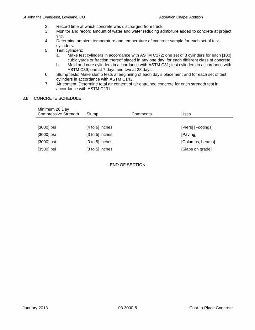
St John the Evangelist, Loveland, CO Adoration Chapel Addition
January 2013 03 3000-5 Cast-In-Place Concrete
2. Record time at which concrete was discharged from truck. 3. Monitor and record amount of water and water reducing admixture added to concrete at project
site. 4. Determine ambient temperature and temperature of concrete sample for each set of test
cylinders. 5. Test cylinders:
a. Make test cylinders in accordance with ASTM C172; one set of 3 cylinders for each [100] cubic yards or fraction thereof placed in any one day, for each different class of concrete.
b. Mold and cure cylinders in accordance with ASTM C31; test cylinders in accordance with ASTM C39; one at 7 days and two at 28 days.
6. Slump tests: Make slump tests at beginning of each day's placement and for each set of test cylinders in accordance with ASTM C143.
7. Air content: Determine total air content of air entrained concrete for each strength test in accordance with ASTM C231.
3.8 CONCRETE SCHEDULE
Minimum 28 Day Compressive Strength
Slump
Comments
Uses
[3000] psi [4 to 6] inches [Piers] [Footings]
[3000] psi [3 to 5] inches [Paving]
[3000] psi [3 to 5] inches [Columns, beams]
[3500] psi [3 to 5] inches [Slabs on grade]
END OF SECTION
St John the Evangelist, Loveland, CO Adoration Chapel Addition
January 2013 03 3500-1 Concrete Finishing
SECTION 03 3500
CONCRETE FINISHING PART 1 GENERAL 1.1 SUMMARY
A. Section Includes: 1. Finishing concrete slabs and formed surfaces. 2. Floor sealer. 3. Colored, Patterned concrete finishes.
B. Related Sections:
1. Division 01: Administrative, procedural, and temporary work requirements. 2. Section 03 3000 - Cast-In-Place Concrete. 3. Section 32 1313 – Concrete Paving.
1.2 REFERENCES
A. American Concrete Institute (ACI): 1. 301 - Structural Concrete for Buildings. 2. 302.1 - Guide for Concrete Floor and Slab Construction.
B. ASTM International (ASTM):
1. C309 - Standard Specification for Liquid Membrane-Forming Compounds for Curing Concrete. 2. E1155 - Standard Test Method for Determining Floor Flatness and Levelness Using the F-
Number System (Inch-Pound Units). 1.3 DEFINITIONS
A. Level: Horizontal, normal to the direction of gravity. An envelope is defined by 2 level lines which are separated by stated distances.
1.4 SUBMITTALS
A. Submittals for Review: 1. Product Data: Descriptive data for sealer, color hardener and curing compound. 2. Color Chart: Manufacturer’s color chart of standard color for initial selection.
1.5 QUALITY ASSURANCE
A. Installer Qualifications: Minimum 5 years experience in work of this Section.
B. Concrete Mix Design: Free from admixtures and additives not specifically approved by colorant manufacturer.
PART 2 PRODUCTS 2.1 MANUFACTURERS
A. Acceptable Manufacturers - Concrete Colorants: 1. Bomanite Corp. (www.bomanite.com) 2. Davis Colors. (www.daviscolors.com) 3. L.M. Scofield Co., Inc. (www.scofield.com) 4. Solomon Colors. (www.solomoncolors.com)
St John the Evangelist, Loveland, CO Adoration Chapel Addition
January 2013 03 3500-2 Concrete Finishing
B. Acceptable Manufacturers - Concrete Sealers: 1. BASF Corporation. (www.buildingsystems.basf.com) 2. Dayton Superior Corporation. (www.daytonsuperior.com) 3. W. R. Meadows, Inc. (www.wrmeadows.com) 4. Nox-Crete Products Group. (www.nox-crete.com)
C. Substitutions: [Under provisions of Division 01.]
2.2 MATERIALS
A. Concrete Materials: Specified in Section 03 3000.
B. Dry-Shake Colorant: by Davis Colors or approved substitute color to be selected from manufacturer's full range of Standard Group colors.
C. Floor Sealer:
1. Type: ASTM C309, water based, acrylic copolymer resin.
D. Pattern Imprinting Tool: 1. Pattern: European Fan.
PART 3 EXECUTION 3.1 FINISHING FORMED SURFACES
A. Concealed Surfaces: Leave texture imparted by forms.
B. Exposed Surfaces: 1. While concrete is still green, patch voids over [1/2] inch in diameter or depth. 2. Chip away defective concrete; form edges perpendicular to surface. Wet area to be patched
with clean water. 3. Apply bonding agent in accordance with manufacturer's instructions. 4. Press mortar into place; strike off slightly higher than surrounding surface. Allow initial
shrinkage to occur before finishing. 5. Finish to match texture and color of adjacent surfaces. 6. Remove fins and other protrusions by rubbing with carborundum stone while concrete is still
green. 3.2 FINISHING INTERIOR FLOOR SURFACES
A. Finish concrete floor surfaces in accordance with ACI 301 and ACI 302.1.
B. Steel trowel slab surfaces.
C. In areas with floor drains, maintain design floor elevation at walls; slope surfaces uniformly to drains at [1/8] inch per foot.
D. Tolerances:
1. Maximum variation of surface flatness under wood flooring on sleepers: [1/4] inch in 10 feet. 2. Maximum variation of surface flatness under tile flooring: [1/8] inch in 10 feet. 3. Correct defects by grinding or removal and replacement of defective work. Re-measure
corrected areas by same process. 3.3 FINISHING EXTERIOR SLAB SURFACES
A. Finish concrete slab surfaces in accordance with ACI 301.
St John the Evangelist, Loveland, CO Adoration Chapel Addition
January 2013 03 3500-3 Concrete Finishing
B. Steel trowel and broom finish surfaces unless otherwise indicated.
C. Steel trowel and color surfaces where scheduled. 1. Apply colorant in accordance with manufacturer's instructions, to uniform coverage. 2. After application work colorant into surface by hand floating or power troweling. 3. After final application power trowel to smooth, hard, dense surface, without burnishing. 4. Prevent overlaps, application patterns, and streaks. 5. Imprint pattern to wet concrete in scheduled pattern. Align pattern across joints and from
pattern row-to-row. 6. Apply color curing compound in accordance with manufacturer's instructions, to uniform
coverage.
D. Tolerances: 1. Maximum variation of surface flatness: [1/4] inch in 10 feet. 2. Correct defects by grinding or removal and replacement of defective work. Re-measure
corrected areas by same process.
END OF SECTION

St John the Evangelist, Loveland, CO Adoration Chapel Addition
January 2013 04 0513-1 Masonry Mortaring
SECTION 04 0513
MASONRY MORTAR AND GROUT PART 1 GENERAL 1.1 SUMMARY
A. Section Includes: 1. Mortar for masonry. 2. Grout for masonry.
B. Related Sections:
1. Division 01: Administrative, procedural, and temporary work requirements. 2. Section 04 2000 - Unit Masonry. 3. Section 04 4000 - Stone Assemblies.
1.2 REFERENCES
A. ASTM International (ASTM): 1. C91 - Standard Specification for Masonry Cement. 2. C144 - Standard Specification for Aggregate for Masonry Mortar. 3. C150 - Standard Specification for Portland Cement. 4. C199 - Standard Test Method for Pier Test for Refractory Mortar. 5. C207 - Standard Specification for Hydrated Lime for Masonry Purposes. 6. C270 - Standard Specification for Mortar for Unit Masonry. 7. C1329 - Standard Specification for Mortar Cement. 8. C404 - Standard Specification for Aggregates for Masonry Grout. 9. C476 - Standard Specification for Mortar and Grout for Reinforced Masonry.
B. The Masonry Society (TMS):
1. 402 - Building Code for Masonry Structures. 2. 602 - Specification for Masonry Structures.
1.3 SUBMITTALS
A. Submittals for Review: 1. Samples:
a. Colored mortar: 1/2 x 1/2 x 3 inch long samples showing available colors.
B. Quality Control Submittals: 1. Test reports: Indicating mortar compliance with ASTM C270.
1.4 QUALITY ASSURANCE
A. Perform Work in accordance with TMS 402 and 602. 1.5 DELIVERY, STORAGE AND HANDLING
A. Deliver cement and lime in manufacturer's original, unopened packages or containers.
B. Protect materials from moisture absorption and damage; reject damaged containers.
C. Store aggregate to prevent inclusion of foreign matter.
St John the Evangelist, Loveland, CO Adoration Chapel Addition
January 2013 04 0513-2 Masonry Mortaring
PART 2 PRODUCTS 2.1 MATERIALS
A. Portland Cement: 1. ASTM C150, Type [I.] 2. For exposed surfaces, provide cement from one source throughout project.
B. Aggregate: ASTM C404.
C. Lime: ASTM C207, Type [S.]
D. Water: Clean and free from oils, acids, alkalies, organic matter, and other substances in amounts
deleterious to mortar or metals in masonry. 2.2 MIXES
A. Mortar Mixes: To ASTM C270 using the [Property] Method. 1. Concrete unit masonry: Type [S,] [gray] color. 2. Stone: Type [N,] color to be selected.
B. Grout Mix:
1. ASTM C476, [coarse] grout. 2. Compressive strength: Minimum [2000] psi at 28 days. 3. Slump: [7 to 8] inches.
2.3 MIXING
A. Mix mortar in accordance with ASTM C270.
B. Mix grout in accordance with ASTM C476.
C. Jobsite Proportioning of Mortar: 1. Mix using mechanical mixer. Hand mixing not permitted. 2. Mix approximately three-quarters of required water, all of cement and lime, and one-half of
aggregate for minimum of 2 minutes. 3. Add remainder of water and aggregate; mix for minimum of 3 minutes.
D. Dry Preblended Mortar:
1. Mix using continuous, self-cleaning mixer mounted at apex of silo cone. 2. Set water flow valve to provide workable consistency.
E. Provide uniformity of color in exposed mortar.
F. Colorant may not exceed [9] pounds per 94 pound bag of cement for mineral oxides.
G. Thoroughly mix ingredients in quantities needed for immediate use.
H. Discard lumpy, caked, frozen, and hardened mixes.
I. Mortar may be retempered by adding water as required. Use mortar and grout within [2-1/2] hours
after initial mixing at ambient temperatures below [80] degrees F and within [1-1/2] hours after initial mixing at ambient temperatures over [80] degrees F.

St John the Evangelist, Loveland, CO Adoration Chapel Addition
January 2013 04 0513-3 Masonry Mortaring
J. Do not add accelerators, retarders, water repellents, antifreeze compounds, or other additives without
Architect's approval. PART 3 EXECUTION 3.1 INSTALLATION
A. Follow requirements specified in referenced sections.
END OF SECTION
St John the Evangelist, Loveland, CO Adoration Chapel Addition
January 2013 04 2000-1 Unit Masonry
SECTION 04 2000
UNIT MASONRY PART 1 GENERAL 1.1 SUMMARY
A. Section Includes: 1. Concrete unit masonry. 2. Integral flashings.
B. Related Sections:
1. Division 01: Administrative, procedural, and temporary work requirements. 2. Section 04 0513 - Masonry Mortar and Grout. 3. Section 07 9200 - Joint Sealers.
1.2 REFERENCES
A. ASTM International (ASTM): 1. A153/A153M - Standard Specification for Zinc-Coating (Hot Dip) on Iron and Steel Hardware. 2. A615/A615M - Standard Specification for Deformed and Plain Billet-Steel Bars for Concrete
Reinforcement. 3. A653/A653M - Standard Specification for Steel Sheet, Zinc-Coated (Galvanized) or Zinc-Iron
Alloy Coated (Galvannealed) by the Hot-Dip Process. 4. A666 - Standard Specification for Annealed or Cold-Worked Austenitic Stainless Steel Sheet,
Strip, Plate, and Flat Bar. 5. A951 - Standard Specification for Masonry Joint Reinforcement. 6. C90 - Standard Specification for Hollow Loadbearing Concrete Masonry Units. 7. C780 - Standard Test Method for Preconstruction and Construction Evaluation of Mortars for
Plain and Reinforced Concrete. 8. C1019 - Standard Test Method for Sampling and Testing Grout.
B. The Masonry Society (TMS):
1. 402 - Building Code for Masonry Structures. 2. 602 - Specification for Masonry Structures.
1.3 SUBMITTALS
A. Submittals for Review: 1. Product Data: Provide information on reinforcing and anchors including sizes, profiles,
materials, and finishes. 1.4 QUALITY ASSURANCE
A. Installer Qualifications: Minimum 5 years experience in work of this Section.
B. Perform Work in accordance with TMS 402 and 602. 1.5 DELIVERY, STORAGE AND HANDLING
A. Store masonry off ground; prevent contact with materials that could cause staining or damage.
B. Protect reinforcement and anchors from corrosion.
St John the Evangelist, Loveland, CO Adoration Chapel Addition
January 2013 04 2000-2 Unit Masonry
1.6 PROJECT CONDITIONS
A. Wall Protection: 1. During erection, cover tops of partially completed walls with strong waterproof membrane at
end of each day or work stoppage. 2. Extend cover minimum of [24] inches down both sides; hold securely in place.
B. Load Application:
1. Do not apply uniform loads for at least [12] hours after building masonry columns or walls. 2. Do not apply concentrated loads for at least [3] days after building masonry columns or walls.
C. Environmental Requirements:
1. Hot weather requirements: If ambient temperature is over [95] degrees F or relative humidity is less than [50] percent, protect from direct sun and wind exposure for minimum [48] hours after installation.
2. Cold weather requirements: Do not use frozen materials or build on frozen work. PART 2 PRODUCTS 2.1 MATERIALS
A. Concrete Masonry Units: 1. ASTM C90, Grade N hollow load bearing type, normal weight. 2. Size: Nominally [8] inches high x [16] inches long x [10] inches thick. 3. Special shapes: [Lintels] [Bond beams] [Solid units].
2.2 ACCESSORIES
A. Mortar and Grout: Specified in Section 04 0513.
B. Single Wythe Joint Reinforcement: 1. [Truss] type; ASTM A951, [hot-dip] galvanized steel wire,] [9] gage side rods with [9] gage cross
ties. 2. Width: Nominal wall thickness less [1-1/2] inches. 3. Corner and tee fittings: Type to match reinforcement.
C. Reinforcing Bars:
1. ASTM A615/A615M, deformed billet steel, Grade [60].
D. Flexible Flashings: 1. Rubberized asphalt laminated to plastic film, release paper facing, self adhering. 2. Termination mastic: Type recommended by flashing manufacturer.
E. Flashings: Galvanized steel, ASTM A653/A653M, G90 coating class, min 29 gage core steel.
F. Weeps: Preformed plastic tubes filled with cotton wicks.
G. Joint Sealer: Specified in Section 07 9200.
H. Cleaner: Type recommended by masonry manufacturer.
St John the Evangelist, Loveland, CO Adoration Chapel Addition
January 2013 04 2000-3 Unit Masonry
PART 3 EXECUTION 3.1 PREPARATION
A. Wet brick having an absorption rate in excess of [20] g per 30 square inches per minute as determined by ASTM C67 so that absorption rate when laid does not exceed this amount.
B. Remove dirt, loose rust, and other foreign matter from reinforcement and anchors.
3.2 INSTALLATION
A. Establish lines, levels and courses indicated. Protect from displacement.
B. Maintain masonry courses to uniform dimensions. Form horizontal and vertical joints of uniform thickness.
C. Lay concrete masonry in [running] bond at walls and [stack] bond at piers. Course one masonry unit
and one mortar joint to equal [8] inches.
D. Lay masonry plumb and level. Do not adjust masonry units after mortar has set.
E. Lay solid masonry units in full mortar bed, with full head joints. Lay hollow masonry units with face shell bedding on head and bed joints.
F. Do not butter corners or excessively furrow joints.
G. Machine cut masonry with straight cuts and clean edges; prevent oversized or undersized joints.
Discard damaged units. Do not expose cut cells.
H. Isolate masonry from structural members with compressible filler.
I. When joining fresh masonry to partially set masonry, remove loose masonry and mortar; clean and lightly wet exposed surface of set masonry.
J. Stop horizontal runs by racking back normal bond unit in each course. Toothing not permitted.
K. Horizontal Reinforcement:
1. Place reinforcement at maximum [16] inches on center vertically, at topmost course, and at first two courses above and below openings.
2. Extend minimum [24] inches each side of openings. 3. Center reinforcing in wall. 4. Lap ends [6] inches minimum; use fabricated tee and corner fittings at corners and
intersections.
L. Control Joints: 1. Do not continue horizontal joint reinforcement through joints. 2. Keep joints free from mortar and grout. 3. Install joint backing and joint sealer at control joints in accordance with Section 07 9200.
M. Finishing Mortar Joints:
1. Concealed locations: Cut joints flush.
St John the Evangelist, Loveland, CO Adoration Chapel Addition
January 2013 04 2000-4 Unit Masonry
N. Reinforcing Bars: 1. Position reinforcing accurately and hold securely in place to prevent displacement. Maintain
minimum [1] inch space between masonry and reinforcing. 2. Grout at intervals of not more than [48] inches in [6 to 8] inch lifts. 3. Vibrate grout during and after placement to ensure complete filling. 4. Stop grout [1-1/2] inch below top of masonry if grouting is stopped for [1] hour or more, except
where completing grouting of finished wall.
O. Flashings: 1. Install flashing with outer edge flush with outside face of masonry; extend up backup [8] inches
minimum and [build into masonry.] [seal.] 2. Lap end joints [4] inches minimum and seal. 3. Form end dams where flashing is stopped or interrupted. 4. [Apply trowel coat of mastic along flashing at top edge, seams, cuts, and penetrations.]
P. Weeps:
1. Locate in head joints in first course above flashings at maximum [32] inches on center. 2. [Set weeps flush with exterior face of masonry.] [Leave head joints open.]
Q. Installation Tolerances; Maximum variation from:
1. Alignment of columns and pilasters: Plus or minus [1/4] inch. 2. Alignment face to face of adjacent units: Plus or minus [1/8] inch. 3. Vertical alignment of head joints: Plus or minus [1/2] inch in 10 feet. 4. True plane of wall: Plus or minus [1/4] inch in 10 feet and [1/2] inch in 20 feet or more. 5. Plumb: Plus or minus [1/4] inch in 10 feet noncumulative; [1/2] inch in 20 feet or more. 6. Level coursing: Plus or minus [1/8] inch in 3 feet; [1/4] inch in 10 feet; [1/2] inch in 30 feet. 7. Joint thickness: Plus or minus [1/8] inch. 8. Cross sectional thickness of walls: Plus or minus [1/4] inch.
3.3 CLEANING
A. Protect adjacent and underlying surfaces.
B. Apply masonry cleaner in accordance with manufacturer's instructions.
C. Thoroughly rinse surfaces with clean water after completion of cleaning; remove all traces of cleaning solution.
END OF SECTION
St John the Evangelist, Loveland, CO Adoration Chapel Addition
January 2013 04 4000-1 Stone Assemblies
SECTION 04 4000
STONE ASSEMBLIES PART 1 GENERAL 1.1 SUMMARY
A. Section Includes: 1. [Cut] stone. 2. Integral flashings.
B. Related Sections:
1. Division 01: Administrative, procedural, and temporary work requirements. 2. Section 04 0513 - Masonry Mortar and Grout. 3. Section 07 9200 - Joint Sealers.
1.2 REFERENCES
A. ASTM International (ASTM): 1. A153/A153M - Standard Specification for Zinc-Coating (Hot Dip) on Iron and Steel Hardware. 2. A653/A653M - Standard Specification for Steel Sheet, Zinc-Coated (Galvanized) or Zinc-Iron
Alloy Coated (Galvannealed) by the Hot-Dip Process. 3. A666 - Standard Specification for Annealed or Cold-Worked Austenitic Stainless Steel Sheet,
Strip, Plate, and Flat Bar. 4. C97 - Standard Test Method for Absorption and Bulk Specific Gravity of Dimension Stone. 5. C99 - Standard Test Method for Modulus of Rupture of Dimension Stone. 6. C119 - Standard Definitions of Terms Relating to Natural Building Stones. 7. C568 - Standard Specification for Limestone Dimension Stone.
B. The Masonry Society (TMS):
1. 402 - Building Code for Masonry Structures. 2. 602 - Specification for Masonry Structures.
1.3 SUBMITTALS
A. Submittals for Review: 1. Product Data: Provide information on anchors including sizes, profiles, materials, and finishes. 2. Samples: [12 x 12] inch stone samples showing color and finish.
1.4 QUALITY ASSURANCE
A. Fabricator and Installer Qualifications: Minimum 5 years experience in work of this Section.
B. Obtain stone from a single quarry and from the same area within the quarry.
C. Perform Work in accordance with TMS 402 and 602. 1.5 DELIVERY, STORAGE AND HANDLING
A. Store stone off ground; prevent contact with materials that could cause staining or damage.
B. Protect anchors from corrosion.
St John the Evangelist, Loveland, CO Adoration Chapel Addition
January 2013 04 4000-2 Stone Assemblies
1.6 PROJECT CONDITIONS
A. Wall Protection: 1. During erection, cover tops of partially completed walls with strong waterproof membrane at
end of each day or work stoppage. 2. Extend cover minimum of [24] inches down both sides; hold securely in place.
B. Environmental Requirements:
1. Hot weather requirements: If ambient temperature is over [95] degrees F or relative humidity is less than [50] percent, protect from direct sun and wind exposure for minimum [48] hours after installation.
2. Cold weather requirements: Do not use frozen materials or build upon frozen work. PART 2 PRODUCTS 2.1 MANUFACTURERS
A. Acceptable Suppliers - Stone: 1. Design Basis: Contract Documents are based on products by The Denver Marble Company.
B. Acceptable Manufacturers - Masonry Accessories:
1. Blok-Lok Ltd. (www.blok-lok.com) 2. Dur-O-Wal. (www.dur-o-wal.com) 3. Heckmann Building Products. (www.heckmannbuildingprods.com) 4. Hohmann and Barnard, Inc. (www.h-b.com)
C. Substitutions: [Under provisions of Division 01.]
2.2 MATERIALS
A. Cut Stone: 1. Type: Limestone, ASTM C568, Classification [II.] 2. Color: [Hillsboro.] 3. Finish: [Honed.] 4. Thickness: [Nominally] [1 ½”] inches. 5. Free from defects that could impair its structural integrity or function. Inherent variations
characteristic to quarry from which it is obtained are acceptable. 2.3 ACCESSORIES
A. Mortar and Grout: Specified in Section 04 0513.
B. Anchors: Stainless steel, ASTM A666, Type [304.]
C. Fasteners: Stainless screws, minimum [3/4] inch penetration into substrate.
D. Flexible Flashings: 1. Rubberized asphalt laminated to plastic film, release paper facing, self adhering. 2. Termination mastic: Type recommended by flashing manufacturer.
E. Flashings: Galvanized steel, ASTM A653/A653M, G90 coating class, min 29 gage core steel.
F. Weeps: Preformed plastic tubes filled with cotton wicks.
St John the Evangelist, Loveland, CO Adoration Chapel Addition
January 2013 04 4000-3 Stone Assemblies
G. Joint Sealer: Specified in Section 07 9200.
H. Cleaner: Type recommended by stone supplier. 2.4 FABRICATION
A. Cut adjacent pieces from same block wherever possible.
B. Fabricate stone for uniform coloration between adjacent units and over full area of installation.
C. Form external stone corners to [square butt] [quirk mitered joint profile. Clean jagged corners from stone in preparation for setting.
D. Fabricate for [1/4] inch beds and joints.
E. Cut or saw bed and joint surfaces square for full thickness of unit.
F. Backs: Sawn.
G. Slope exposed top surfaces of stone and horizontal sill surfaces for shedding water.
H. Cut drip slot in stone projecting more than [1] inch. Size slot not less than [1/4] inch wide and deep for
full width of projection.
I. Provide holes and cutouts to accommodate items attached to stone.
J. Groove out edges of stone to recess anchors below setting bed.
K. Fabrication Tolerances: 1. Variation in width or height: Plus or minus [1/16] inch. 2. Variation in thickness: Plus or minus [1/8] inch. 3. Variation from true plane: Plus or minus [1/16] inch in 3 feet.
PART 3 EXECUTION 3.1 PREPARATION
A. Establish lines, levels, and coursing. Protect from disturbance.
B. Clean stone prior to installation. Do not use wire brushes or implements that can mark or damage exposed surfaces.
C. Wet absorptive stone in preparation for placement to minimize moisture suction from mortar.
3.2 INSTALLATION - ANCHORED
A. Install in accordance with approved Shop Drawings.
B. Arrange stone pattern to provide color uniformity and constant [1/4] inch joint sizes throughout, except provide ¾” joint at foundation, recessed to receive joint sealer.
C. Anchor stone to backup construction with edge anchors:
1. Space anchors maximum [24] inches on center around perimeter 2. Provide minimum of four anchors per panel.
St John the Evangelist, Loveland, CO Adoration Chapel Addition
January 2013 04 4000-4 Stone Assemblies
D. Set stone plumb and level. Align adjacent pieces in same plane.
E. Obtain approval prior to cutting or fitting any item not so indicated on Drawings. Do not impair
appearance or strength of stone work by cutting.
F. Set stone in full mortar setting bed; support stone over full bearing surface.
G. Set stone to stack pattern.
H. Completely fill beds and joints, then rake out for pointing.
I. Fill joints with pointing mortar; tool to concave profile.
J. Install anchors and place spacers to support stone and to establish joint dimensions.
K. Flashings: 1. Install flashing with outer edge flush with outside face of stone; extend up backup 8 inches
minimum and build into masonry. 2. Lap end joints [4] inches minimum and seal. 3. Form end dams where flashing is stopped or interrupted. 4. Apply trowel coat of mastic along flashing at top edge, seams, cuts, and penetrations.
L. Weeps:
1. Locate in head joints in first course above flashings at maximum [32] inches on center. 2. Set weeps flush with exterior face of masonry. Leave head joints open.
M. Control Joints:
1. Keep joints free from mortar and grout. 2. Install joint backing and joint sealer at control joints in accordance with Section 07 9200.
N. Installation Tolerances; Maximum variation from:
1. Alignment of columns and pilasters: Plus or minus [1/4] inch. 2. Alignment face to face of adjacent units: Plus or minus [1/8] inch. 3. Vertical alignment of head joints: Plus or minus [1/2] inch in 10 feet. 4. True plane of wall: Plus or minus [1/4] inch in 10 feet and [1/2] inch in 20 feet or more. 5. Plumb: Plus or minus [1/4] inch in 10 feet noncumulative; [1/2] inch in 20 feet or more. 6. Level coursing: Plus or minus [1/8] inch in 3 feet; [1/4] inch in 10 feet; [1/2] inch in 30 feet. 7. Joint thickness: Plus or minus [1/8] inch. 8. Cross sectional thickness of walls: Plus or minus [1/4] inch.
3.3 CLEANING
A. Clean stone with detergent and water applied with fiber brush.
B. If initial cleaning does not produce acceptable results, apply cleaner in accordance with manufacturer's instructions. 1. Protect adjacent surfaces. 2. Thoroughly rinse surfaces with clean water after completion of cleaning; remove all traces of
cleaning solution.
END OF SECTION
St John the Evangelist, Loveland, CO Adoration Chapel Addition
January 2013 04 7300-1 Natural Thin Stone Veneer
SECTION 04 7300
NATURAL THIN STONE VENEER PART 1 GENERAL 1.1 SUMMARY
A. Section Includes: 1. Natural thin stone veneer applied to masonry substrate. 2. Pointing mortar joints.
B. Related Sections:
1. Division 01: Administrative, procedural, and temporary work requirements. 2. Section 04 0513 - Masonry Mortar and Grout.
1.2 REFERENCES
A. ASTM International (ASTM): 1. ACI 530.1/ASCE 6/TMS 602 – Specifications for Masonry Structures. 2. ASTM C 568 – Standard Specification for Limestone Dimension Stone. 3. PCA – Portland Cement Plaster (Stucco) Manual.
1.3 SUBMITTALS
A. Submittals for Review: 1. Product Data: Descriptive data and installation instructions. 2. Samples: Full size stone samples showing profile and finish.
1.4 QUALITY ASSURANCE
A. Installer Qualifications: Minimum 5 years experience in work of this Section. 1.5 PROJECT CONDITIONS
A. Environmental Requirements: 1. Hot weather requirements: If ambient temperature is over 95 degrees F or relative humidity is
less than 50 percent, protect from direct sun and wind exposure for minimum 48 hours after installation.
2. Cold weather requirements: a. Do not install stone when ambient temperature is below 40 degrees F or is expected to
fall below that level within 12 hours after installation. b. Do not use frozen materials or build upon frozen work.
PART 2 PRODUCTS 2.1 MANUFACTURERS
A. Acceptable Manufacturers – Natural Thin Stone Veneer: 1. Design Basis: Contract Documents are based on products by [Cooper Stone Corporation,
www.cooperstone.com ].
B. Substitutions: [Under provisions of Division 01.]
St John the Evangelist, Loveland, CO Adoration Chapel Addition
January 2013 04 7300-2 Natural Thin Stone Veneer
2.2 MATERIALS
A. Natural Thin Stone: 1. Material: Limestone, type III high-density, per ASTM C 568. 2. Size, color, and surface texture: To be selected from the manufacturer's following Ledgestone
products: a) Navajo b) Brazos c) Seminole d) Mountain
3. Trim units: Corner profile, color and surface texture to match field stone. 2.3 ACCESSORIES
A. Mortar: Specified in Section 04 0513.
B. Bonding Agent: Type recommended by simulated stone manufacturer for direct bonding of stone to masonry or concrete substrates.
C. Cleaner: Type recommended by stone manufacturer.
PART 3 EXECUTION 3.1 SURFACE PREPARATION
A. Application of Base Coat Stucco: 1. Apply scratch coat in accordance with PCA Plaster (Stucco) Manual.
B. Prepare for Installation of Thin Veneer Stone:
1. Coordination: Coordinate placement of reinforcement, anchors, accessories, flashings , weep holes, etc specified in other sections
2. Cleaning: Clean built-in items of loose rust, ice, mud, and other foreign matter before incorporating into wall.
1.1 INSTALLATION OF STONE
A. Install stone in accordance with manufacturer’s instructions and ACI 530.1/ASCE 6/TMS 602.
B. Blend stone from multiple boxes before installing.
C. Apply bonding agent to substrate in accordance with manufacturer’s instructions.
D. Apply [3/8 to 1/2] inch thick mortar completely covering back of each stone.
E. Maintain masonry courses to uniform dimensions. Do not use stacked vertical joints.
F. Place stone in ledgestone pattern.
G. Arrange stone pattern to provide [uniform] color throughout.
H. Set stone plumb and level.
I. Press stone to full contact with mortar.
St John the Evangelist, Loveland, CO Adoration Chapel Addition
January 2013 04 7300-3 Natural Thin Stone Veneer
J. Place stone with [uniform [3/8] inch wide] joints; tool to [concave] profile.
1.2 CLEANING
A. Clean stone with detergent and water applied with fiber brush.
B. If initial cleaning does not produce acceptable results, apply cleaner in accordance with manufacturer's instructions. 1. Protect adjacent surfaces. 2. Thoroughly rinse surfaces with clean water after completion of cleaning; remove all traces of
cleaning solution.
END OF SECTION

St John the Evangelist, Loveland, CO Adoration Chapel Addition
January 2013 05 1200-1 Structural Steel Framing
SECTION 05 1200
STRUCTURAL STEEL FRAMING PART 1 GENERAL 1.1 SUMMARY
A. Section Includes: 1. Structural steel framing members. 2. Grouting base plates.
B. Related Sections:
1. Division 01: Administrative, procedural, and temporary work requirements. 1.2 REFERENCES
A. American Institute of Steel Construction (AISC) - Specifications for Structural Steel Buildings.
B. American Welding Society (AWS) D1.1 - Structural Welding Code - Steel.
C. ASTM International (ASTM): 1. A36/A36M - Standard Specification for Carbon Structural Steel. 2. A53/A53M - Standard Specification for Pipe, Steel, Black and Hot-Dipped, Zinc-Coated,
Welded and Seamless. 3. A108 - Standard Specification for Steel Bars, Carbon, Cold-Finished, Standard Quality. 4. A307 - Standard Specification for Low-Carbon Steel Externally and Internally Threaded
Standard Fasteners. 5. A325 - Standard Specification for High-Strength Bolts for Structural Steel Joints, Including
Suitable Nuts and Plain Hardened Washers. 6. A490 - Standard Specification for Quenched and Tempered Alloy Steel Bolts for Structural
Steel Joints. 7. A500 - Standard Specification for Cold-Formed Welded and Seamless Carbon Steel Structural
Tubing in Rounds and Shapes. 8. A501 - Standard Specification for Hot-Formed Welded and Seamless Carbon Steel Structural
Tubing. 9. A572/A572M - Standard Specification for High Strength Low Alloy Columbium-Vanadium Steels
of Structural Quality. 10. A992/A992M - Standard Specification for Steel for Structural Shapes. 11. C109 - Standard Test Method for Compressive Strength of Hydraulic Cement Mortars (Using 2-
In. or 50-mm Cube Specimens). 12. E164 - Standard Practice for Ultrasonic Contact Examination of Weldments.
D. Society for Protective Coatings (SSPC) - Painting Manual.
1.3 SUBMITTALS
A. Submittals for Review: 1. Shop Drawings: Indicate profiles, sizes, spacing, and location of structural members, openings,
attachments, and fasteners, and connections not detailed.
B. Quality Control Submittals: 1. Welder Qualifications: As required by AWS D1.1.
St John the Evangelist, Loveland, CO Adoration Chapel Addition
January 2013 05 1200-2 Structural Steel Framing
1.4 QUALITY ASSURANCE
A. Fabricator and Erector Qualifications: Minimum 5 years experience in work of this Section.
B. Welder Qualifications: AWS D1.1.
C. Design Requirements: Design connections not detailed on Drawings under supervision of a Professional Structural Engineer experienced in this work and registered in the State in which the project is located.
1.5 DELIVERY, STORAGE AND HANDLING
A. Store steel above ground on platforms, skids, or other supports; separate with wooden separators.
B. Protect steel from corrosion.
C. Prevent damage to prime coat; use wooden protectors to prevent damage from chain or cable cinches.
PART 2 PRODUCTS 2.1 MATERIALS
A. Steel: 1. Shapes, bars, and plates: [ASTM A36/A36M.], Grade [50.] 2. Hollow structural sections: ASTM A500, Grade B. 3. Pipe: [ASTM A53/A53M, Grade B.] 4. Shear Connectors: ASTM A108, Grade [1015,] forged steel, headed, unfinished.
2.2 ACCESSORIES
A. Anchor Bolts: ASTM A307.
B. High Strength Bolts: ASTM A325, Type 1, uncoated.
C. Standard Bolts: ASTM A307, Grade A.
D. Primer Paint: SSPC Paint 15, Type 1, red oxide.
E. Non Shrink Grout: Premixed, consisting of non-metallic aggregate, cement, water reducing and plasticizing agents; minimum [4,000] PSI compressive strength at 28 days.
F. Welding Materials: AWS D1.1, type required for materials being welded.
2.3 FABRICATION
A. Fabricate structural steel in accordance with AISC Manual.
B. Welding: AWS D1.1. Stress relieve welded assemblies by heat treatment.
C. Where collection of water inside structural tubing could occur, provide drain hole at lowest point.
D. Cap open ends of tubes and seal weld. Wherever practical, weld connections all around. Seal seams that cannot be practically welded with joint sealer.
St John the Evangelist, Loveland, CO Adoration Chapel Addition
January 2013 05 1200-3 Structural Steel Framing
PART 3 EXECUTION 3.1 ERECTION OF STEEL FRAMING
A. Erect structural steel in accordance with AISC Specifications.
B. Accurately assemble to lines and elevations indicated, within specified erection tolerances.
C. Align and adjust members forming parts of complete frame or structure after assembly but before fastening.
D. Provide temporary shoring and bracing members with connections of sufficient strength to resist
imposed loads.
E. Align bearing plates with wedges or shims.
F. Fasten splices of compression members after abutting surfaces have been brought completely into contact.
G. Clean bearing surfaces and surfaces that will be in permanent contact before members are
assembled.
H. Locate splices only where indicated.
I. [Tighten erection bolts and leave in place.]
J. Do not correct fabrication by gas cutting on major members.
K. Remove temporary shoring and bracing members after permanent members are in place and final connections have been made.
L. Installation Tolerances:
1. Maximum variation from level: [1/4] inch in 10 feet, noncumulative. 2. Maximum offset from alignment of adjacent members: [1/4] inch.
3.2 PLACEMENT OF GROUT
A. Remove loose and foreign matter from concrete; lightly roughen bonding surface.
B. Remove foreign materials from steel surfaces; align and level members in final position.
C. Just prior to grouting, thoroughly wet concrete surfaces; remove excess water.
D. Mix grout in accordance with manufacturer's instructions. Do not retemper.
E. Do not remove leveling shims for at least 48 hours after grouting. After removing shims, fill voids with sand-cement grout.
END OF SECTION
St John the Evangelist, Loveland, CO Adoration Chapel Addition
January 2013 05 2100-1 Steel Joist Framing
SECTION 05 2100
STEEL JOIST FRAMING PART 1 GENERAL 1.1 SUMMARY
A. Section Includes: 1. Open web steel joists and joist girders. 2. Bridging and attached seats.
B. Related Sections:
1. Division 01: Administrative, procedural, and temporary work requirements. 1.2 REFERENCES
A. American Welding Society (AWS) D1.1 - Structural Welding Code - Steel.
B. ASTM International (ASTM): 1. A36/A36M - Standard Specification for Carbon Structural Steel. 2. A307 - Standard Specification for Carbon Steel Externally Threaded Standard Fasteners. 3. A572/A572M - Standard Specification for High Strength Low Alloy Columbium-Vanadium Steels
of Structural Quality.
C. Society for Protective Coatings (SSPC) - Painting Manual.
D. Steel Joist Institute (SJI) - Standard Specifications and Load Tables for Steel Joists and Joist Girders. 1.3 SUBMITTALS
A. Submittals for Review: 1. Shop Drawings:
a. Include joist identification numbers, types, locations spacings; bridging; and attachments. b. Joists for which standard load tables are not applicable: Bear seal of structural engineer
licensed in State in which project is located. 1.4 QUALITY ASSURANCE
A. Fabricator and Erector Qualifications: Minimum 5 years experience in work of this Section.
B. Welder Qualifications: AWS D1.1. 1.5 DELIVERY, STORAGE AND HANDLING
A. Store joists off ground; prevent contact with adjacent joists.
B. Prevent damage to painted surfaces.
St John the Evangelist, Loveland, CO Adoration Chapel Addition
January 2013 05 2100-2 Steel Joist Framing
PART 2 PRODUCTS 2.1 MANUFACTURERS
A. Design Basis: Contract Documents are based on products by [Vulcraft Div., Nucor Corp. (www.vulcraft.com].
B. Substitutions: [Under provisions of Division 01.]
2.2 MATERIALS
A. Steel Shapes: 1. [ASTM A572/A572M, Grade [50.]
2.3 ACCESSORIES
A. Bolts, Nuts, and Washers: ASTM A307.
B. Welding Materials: AWS D1.1; type required for materials being welded. 2.4 FABRICATION
A. Fabricate joists to SJI [Series K] requirements.
B. Provide end extensions where indicated.
C. Frame special sized openings in joist chord framing as indicated.
D. Provide bracing, bridging, anchors, connectors, and other accessories. PART 3 EXECUTION 3.1 ERECTION
A. Erect joists and accessories in accordance with SJI Specifications.
B. Provide for distribution of concentrated loads incurred during erection.
C. Complete bridging and permanently fasten joists in place before applying loads except as necessary for erection.
D. Welding to conform to AWS D1.1.
E. Erect joists to elevations, lines, and spacings indicated.
F. Coordinate placement of anchors in other construction for securing bearing plates and wall
attachments.
G. Frame openings greater than [18] inches with supplementary framing.
H. Position and field weld joist chord extensions and wall attachments.
END OF SECTION
St John the Evangelist, Loveland, CO Adoration Chapel Addition
January 2013 05 3123-1 Steel Roof Decking
SECTION 05 3123
STEEL ROOF DECKING PART 1 GENERAL 1.1 SUMMARY
A. Section Includes: 1. Steel roof deck.
B. Related Sections:
1. Division 01: Administrative, procedural, and temporary work requirements. 1.2 REFERENCES
A. American Iron and Steel Institute (AISI) - Specifications for Design of Light Gage Structural Members.
B. American Welding Society (AWS) D1.3 - Structural Welding Code - Sheet Steel.
C. ASTM International (ASTM): 1. A653/A653M - Standard Specification for Steel Sheet, Zinc-Coated (Galvanized) or Zinc-Iron
Alloy-Coated (Galvannealed) by the Hot-Dip Process. 2. A1008/A1008M - Standard Specification for Steel, Sheet, Cold-Rolled, Carbon, Structural,
High-Strength Low-Alloy and High-Strength Low-Alloy with Improved Formability.
D. Society for Protective Coatings (SSPC) - Painting Manual.
E. Steel Deck Institute (SDI) - Design Manual for Composite Decks, Form Decks, and Roof Decks. 1.3 SUBMITTALS
A. Submittals for Review: 1. Product Data: Provide deck profile, characteristics, dimensions, structural properties, and finish.
1.4 QUALITY ASSURANCE
A. Manufacturer and Installer Qualifications: Minimum 5 years experience in work of this Section.
B. Welder Qualifications: AWS D1.3.
C. Perform work in accordance with SDI Manual. 1.5 DELIVERY, STORAGE AND HANDLING
A. Store decking off ground at site, with one end elevated to provide drainage; protect with waterproof covering, properly vented.
PART 2 PRODUCTS 2.1 MANUFACTURERS
A. Design Basis: Contract Documents are based on products by [Vulcraft Div., Nucor Corp. (www.vulcraft.com].
St John the Evangelist, Loveland, CO Adoration Chapel Addition
January 2013 05 3123-2 Steel Roof Decking
B. Equivalent products by following manufacturers are acceptable:
1. Cordeck. (www.cordeck.com) 2. Epic Metals Corp. (www.epicmetals.com)
C. Substitutions: Under provisions of Division 01.
2.2 MATERIALS
A. Steel Sheet: 1. ASTM [A1008/A1008M, unfinished.]
2.3 ACCESSORIES
A. Touch Up Paint: SSPC Paint 20, Type I or II.
B. Fasteners: [Hot-dip galvanized] [Fluoropolymer coated] steel, self tapping.
C. Welding Materials: AWS D1.3; type required for materials being welded. 2.4 FABRICATION
A. Fabricate deck and accessories to SDI Design Manual.
B. Minimum Material Thickness: [18] gage, excluding finish.
C. Formed Sheet Width: [36] inches.
D. Minimum Depth: [1-1/2] inches.
E. Side Joints: [Lapped.]
F. Form units to span three or more supports, with lapped ends and nesting side laps.
G. Accessory Strips: Fabricate metal closure strips and cover plates of [22] gage sheet steel.
H. Apply manufacturer's standard painted finish, sprayed and baked, to deck and accessories. PART 3 EXECUTION 3.1 INSTALLATION
A. Install decking and accessories in accordance with manufacturer's instructions, SDI Design Manual, and approved Shop Drawings.
B. Lap ends [2 to 4] inches. Center laps over supports.
C. Do not stretch or contract side lap interlocks.
D. Place deck units flat and square, without warp or deflection.
E. Provide minimum [1-1/2] inch bearing on steel supports, minimum [4] inch bearing on other materials.
F. Weld decking to supporting members. Welding to conform to AWS D1.3.
St John the Evangelist, Loveland, CO Adoration Chapel Addition
January 2013 05 3123-3 Steel Roof Decking
G. Weld side laps between adjacent deck units at maximum [24] inches on center.
H. Cut and fit deck and accessories at perimeter and around projections and openings. Make cuts neat
and trim.
I. Provide strips for support of roof insulation where rib openings in top surface of roof decking occur adjacent to edges and openings. Weld strips into position.
J. Provide minimum [6] inch wide cover strips where deck changes direction. Weld or mechanically
fasten strips into position.
K. Install closures and angle flashings to close openings between deck and walls, columns, and openings.
3.2 ADJUSTING
A. Touch Up: 1. Wire brush and clean scarred areas, welds, and rust spots on decking units and supporting
steel members. 2. Touch up paint finish with same paint used in shop; apply as recommended by manufacturer.
END OF SECTION
St John the Evangelist, Loveland, CO Adoration Chapel Addition
January 2013 05 5000-1 Metal Fabrications
SECTION 05 5000
METAL FABRICATIONS PART 1 GENERAL 1.1 SUMMARY
A. Section Includes: 1. Shop fabricated metal components.
B. Related Sections:
1. Division 01: Administrative, procedural, and temporary work requirements. 1.2 REFERENCES
A. American Architectural Manufacturers Association (AAMA): 1. 2603 - Voluntary Specification, Performance Requirements and Test Procedures for Pigmented
Organic Coatings on Architectural Extrusions and Panels. 2. 2604 - Voluntary Specification, Performance Requirements and Test Procedures for High
Performance Organic Coatings on Architectural Extrusions and Panels. 3. 2605 - Voluntary Specification, Performance Requirements and Test Procedures for Superior
Performing Organic Coatings on Architectural Extrusions and Panels.
B. American Welding Society (AWS): 1. D1.1 - Structural Welding Code - Steel.
C. ASTM International (ASTM):
1. A36/A36M - Standard Specification for Carbon Structural Steel. 2. A47/A47M - Standard Specification for Ferritic Malleable Iron Castings. 3. A48/A48M - Standard Specification for Gray Iron Castings. 4. A108 - Standard Specification for Steel Bars, Carbon, Cold-Finished, Standard Quality. 5. A123/A123M - Standard Specification for Zinc (Hot-Galvanized) Coatings on Iron and Steel
Products. 6. A283 - Standard Specification for Low and Intermediate Tensile Strength Carbon Steel Plates,
Shapes and Bars. 7. A307 - Standard Specification for Carbon Steel Externally Threaded Standard Fasteners. 8. A354 - Standard Specification for Quenched and Tempered Alloy Steel Bolts, Studs, and Other
Externally Threaded Fasteners. 9. A500 - Standard Specification for Cold-Formed Welded and Seamless Carbon Steel Structural
Tubing in Rounds and Shapes. 10. A501 - Standard Specification for Hot-Formed Welded and Seamless Carbon Steel Structural
Tubing. 11. A510 - Standard Specification for General Requirements for Wire Rods and Coarse Round
Wire, Galvanized Steel. 12. A666 - Standard Specification for Annealed or Cold-Worked Austenitic Stainless Steel Sheet,
Strip, Plate, and Flat Bar. 13. A780 - Standard Practice for Repair of Damaged and Uncoated Areas of Hot-Dip Galvanized
Coatings. 14. A1008/A1008M - Standard Specification for Steel, Sheet, Cold-Rolled, Carbon, Structural,
High-Strength Low-Alloy and High-Strength Low-Alloy with Improved Formability. 15. A1011/A1011M - Standard Specification for Steel, Sheet and Strip, Hot-Rolled, Carbon,
Structural, High-Strength, Low-Alloy and High-Strength Low-Alloy with Improved Formability.
St John the Evangelist, Loveland, CO Adoration Chapel Addition
January 2013 05 5000-2 Metal Fabrications
D. Society for Protective Coatings (SSPC) - Painting Manual. 1.3 SUBMITTALS
A. Submittals for Review: 1. Shop Drawings: Show dimensions, metal thicknesses, finishes, joints, attachments, and
relationship of work to adjacent construction. 1.4 QUALITY ASSURANCE
A. Fabricator Qualifications: Minimum 5 years experience in work of this Section. PART 2 PRODUCTS 2.1 MATERIALS - STEEL
A. Shapes: ASTM A36/A36M.
B. Plate: ASTM A283.
C. Sheet: ASTM A1008/A1008M.
D. Pipe: ASTM A501.
E. Tube: ASTM A500.
F. Bars: ASTM A108. 2.2 ACCESSORIES
A. Exposed Screws: Same material as metal being fastened; Phillips flat head, countersunk, unless noted otherwise.
B. Bolts: ASTM A307, hexagonal head type.
C. Primer Paint: SSPC Paint 15, Type 1, red oxide.
2.3 FABRICATION
A. Fit and shop assemble items in largest practical sections, for delivery to site.
B. Fabricate items with joints tightly fitted and secured.
C. Grind exposed joints flush and smooth with adjacent finish surface. Make exposed joints butt tight, flush, and hairline. Ease exposed edges to small uniform radius.
D. Exposed Mechanical Fastenings: Flush countersunk screws or bolts, unobtrusively located,
consistent with design of component except where specifically noted otherwise.
E. Supply components required for anchorage of fabrications. Fabricate anchors and related components of same material and finish as fabrication, except where specifically noted otherwise.
F. Conceal fastenings where possible.
St John the Evangelist, Loveland, CO Adoration Chapel Addition
January 2013 05 5000-3 Metal Fabrications
G. Welding to conform to AWS [D1.1].
1. Use welds for permanent connections where possible. Grind exposed welds smooth. 2. Tack welds prohibited on exposed surfaces.
2.4 FINISHES
A. Exterior Ferrous Metal: Galvanized; ASTM A123/A123M, to [1.3] ounces per square foot.
B. Interior Ferrous Metal: 1. Shop painted except steel to be encased in concrete and surfaces to be welded. 2. Surface preparation: SSPC SP2 - Hand Tool Cleaning or SP3 - Power Tool Cleaning. 3. Application: One coat; follow coating manufacturer's instructions. 4. Minimum dry film thickness: [2.0] mils.
PART 3 EXECUTION 3.1 INSTALLATION
A. Install items in accordance with approved Shop Drawings.
B. Install components plumb, level, and rigid.
C. Welding: AWS [D1.1]. Grind and fill exposed welds; finish smooth and flush.
D. Install sleeved components with anchoring cement. 3.2 ADJUSTING
A. Clean and touch up damaged primer paint with same product as applied in shop.
B. Clean and touch up galvanized coatings at welded and abraded surfaces in accordance with ASTM A780, Annex [A2.]
END OF SECTION

St John the Evangelist, Loveland, CO Adoration Chapel Addition
January 2013 06 4100-1 Architectural Wood Casework
SECTION 06 4100
ARCHITECTURAL WOOD CASEWORK PART 1 GENERAL 1.1 SUMMARY
A. Section Includes: 1. Plastic laminate countertops.
B. Related Sections:
1. Division 01: Administrative, procedural, and temporary work requirements. 2. Section 07 9200 - Joint Sealers.
1.2 REFERENCES
A. Architectural Woodwork Institute/Architectural Woodwork Manufacturers of Canada/Woodwork Institute (AWI/AWMAC/WI) - Architectural Woodwork Standards.
1.3 SUBMITTALS
A. Submittals for Review: 1. Shop Drawings:
a. Include dimensioned plan, sections, elevations, and details, including interface with adjacent work.
b. Designate wood species and finishes. 2. Samples:
a. [1 x 2] inch plastic laminate samples showing available colors and finishes. 1.4 QUALITY ASSURANCE
A. Fabricator Qualifications: 1. Minimum [5] years experience in work of this Section.
1.5 DELIVERY, STORAGE AND HANDLING
A. Do not deliver materials until proper protection can be provided, and until needed for installation. 1.6 PROJECT CONDITIONS
A. Environmental Requirements: Maintain following conditions in building for minimum 7 days prior to, during, and after installation of casework: 1. Temperature: [60 to 80] degrees F. 2. Humidity: [17 to 50] percent.
PART 2 PRODUCTS 2.1 MANUFACTURERS
A. Acceptable Manufacturers - Plastic Laminate: 1. Products by following manufacturers are acceptable:
a. Formica Corp. (www.formica.com) b. Nevamar Co. (www.nevamar.com)
St John the Evangelist, Loveland, CO Adoration Chapel Addition
January 2013 06 4100-2 Architectural Wood Casework
c. Wilsonart International, Inc. (www.wilsonart.com)
B. Substitutions: [Under provisions of Division 01.] 2.2 MATERIALS
A. Sheet Products: 1. Graded in accordance with AWI/AWMAC/WI Architectural Woodwork Standards, Section 4
requirements for quality grade specified. 2. Exposed and semi-exposed veneers: Closed grain hardwood, of quality suitable for opaque
finish. 3. Sheet core: Particleboard.
B. Lumber:
1. Graded in accordance with AWI/AWMAC/WI Architectural Woodwork Standards, Section 3 requirements for quality grade specified, average moisture content of [6] percent.
C. Plastic Laminate: NEMA LD-3. 1. High pressure decorative laminate:
a. Horizontal surfaces: 1) Backing sheet: Grade [BGF.] 2) Postformed surfaces: Grade [HGP.] 3) Acid resisting: Grade [LGP.] 4) Other surfaces: Grade [HGS.]
2. Low pressure decorative laminate: Grade VGL. 3. Colors: [To be selected from manufacturer's full color range.] 4. Finish: [Matte.]
2.3 ACCESSORIES
A. Fasteners: Type and size as required by conditions of use.
B. Adhesives: 1. Waterproof, [water based] type, compatible with backing and [laminate] materials.
C. Joint Sealers: Specified in Section 07 9200.
2.4 FABRICATION
A. Plastic Laminate Countertops: 1. Quality: AWI/AWMAC/WI Architectural Woodwork Standards, Section 11, [Custom] Grade. 2. Fabricate from sheet product with lumber fronts. 3. Provide holes and cutouts for mounting of sinks and accessories.
B. Shop assemble for delivery to project site in units easily handled.
C. Prior to fabrication, field verify dimensions to ensure correct fit.
D. Apply plastic laminate in full uninterrupted sheets; fit corners and joints to hairline. Slightly bevel
arises. Apply laminate backing sheet to reverse side of laminate faced surfaces.
E. Provide cutouts and reinforcement for plumbing, and accessories. Prime paint surfaces of cut edges.
St John the Evangelist, Loveland, CO Adoration Chapel Addition
January 2013 06 4100-3 Architectural Wood Casework
PART 3 EXECUTION 3.1 PREPARATION
A. Prior to installation, condition cabinets to average humidity that will prevail after installation. 3.2 INSTALLATION
A. Install in accordance with AWI/AWMAC/WI Architectural Woodwork Standards.
B. Set plumb, rigid and level.
C. Scribe to adjacent construction with maximum [1/8] inch gaps.
D. Adhere countertops, splashes, and skirts with beads of adhesive.
E. Fill joints between countertops, splashes, and adjacent construction with joint sealer as specified in Section 07 9200; finish flush.
END OF SECTION
St John the Evangelist, Loveland, CO Adoration Chapel Addition
January 2013 06 4600-1 Wood Trim
SECTION 06 4600
WOOD TRIM PART 1 GENERAL 1.1 SUMMARY
A. Section Includes: 1. Interior wood trim.
B. Related Sections:
1. Division 01: Administrative, procedural, and temporary work requirements. 2. Division 09: Wood Flooring: wood flooring material to match for chapel walls and ceiling.
1.2 REFERENCES
A. American Wood Protection Association (AWPA) U1 - Use Category System - User Specification for Treated Wood.
B. Architectural Woodwork Institute/Architectural Woodwork Manufacturers of Canada/Woodwork
Institute (AWI/AWMAC/WI) - Architectural Woodwork Standards.
C. ASTM International (ASTM) E84 - Standard Test Method for Surface Burning Characteristics of Materials.
1.3 SUBMITTALS
A. Submittals for Review: 1. Samples: [6] inch long samples of each profile.
1.4 QUALITY ASSURANCE
A. Fabricator Qualifications: 1. Minimum [5] years experience in work of this Section.
B. Pre-Installation Conference:
1. Convene [1] week prior to beginning work of this Section. 2. Attendance: Architect, Owner, Contractor, installer, and related trades. 3. Review, discuss and resolve:
a. Critical dimensions. b. Staging and sequencing. c. Protection of completed work.
1.5 DELIVERY, STORAGE AND HANDLING
A. Do not deliver materials until proper protection can be provided, and until needed for installation. 1.6 PROJECT CONDITIONS
A. Environmental Requirements: Maintain following conditions in building for minimum 7 days prior to, during, and after installation of interior trim: 1. Temperature: [60 to 80] degrees F. 2. Humidity: [17 to 50] percent.
St John the Evangelist, Loveland, CO Adoration Chapel Addition
January 2013 06 4600-2 Wood Trim
PART 2 PRODUCTS 2.1 MATERIALS
A. Interior Trim: 1. Graded in accordance with AWI/AWMAC/WI Architectural Woodwork Standards, Section 3
requirements for quality grade specified, average moisture content of [6] percent. 2. Northern Maple species, of quality suitable for [transparent] finish
B. Wood Trim to Match Strip Flooring (on walls and ceiling of Chapel): 1. Species: Northern Hard Maple. 2. Grade: 1st Grade, to MFMA standards. 3. Nominal size: 3/4 inches thick x 3 1/4 inches wide. 4. Edge configuration: Tongue and groove, end matched. 5. Moisture content: Average of 6 to 9 percent with maximum 5 percent outside of this range;
maximum of 12 percent on any individual piece. 2.2 ACCESSORIES
A. Fasteners: Type and size as required by conditions of use; plain steel for interior use; hot dip galvanized steel for exterior use.
B. Adhesives:
1. Waterproof, water based type, compatible with trim and substrate materials. 2.3 FABRICATION
A. Quality: AWI/AWMAC/WI Architectural Woodwork Standards, Section 6, Custom Grade.
B. Where field fitting is required, provide ample allowance for cutting.
C. Groove back of trim applied to flat substrate, except do not groove exposed ends. PART 3 EXECUTION 3.1 PREPARATION
A. Prior to installation, condition wood to average humidity that will prevail after installation.
B. Back prime wood installed against masonry prior to installation. 3.2 INSTALLATION
A. Install in accordance with AWI/AWMAC/WI Architectural Woodwork Standards.
B. Set plumb and level. Miter ends, corners, and intersections. Scribe to adjacent construction with maximum [1/16] inch gaps
C. Coordinate with flooring installation to provide continuously aligned joints across floor, wall and
ceiling.
END OF SECTION

St John the Evangelist, Loveland, CO Adoration Chapel Addition
January 2013 07 1400-1 Dampproofing
SECTION 07 1400
FLUID-APPLIED DAMPPROOFING
PART 1 GENERAL
1.01 SECTION INCLUDES
A. Fluid applied membrane dampproofing.
1.02 RELATED SECTIONS
A. Section 07212 - Board and Batt Insulation: Insulation used for protective cover.
B. Section 07620 - Sheet Metal Flashing and Trim: Metal counterflashings.
1.03 REFERENCES
A. ASTM C 836 - Standard Specification for High Solids Content, Cold Liquid-Applied Elastomeric Waterproofing Membrane for use with Separate Wearing Course; 2006.
B. ASTM 3294 - Resistance to Mold Growth of Surface Coating, 1994.
C. ASTM D 746 - Standard Test Method for Brittleness Temperature of Plastics and Elastomers by Impact; 2004.
D. ASTM D 4541 - Standard Test Method for Pull-Off Strength of Coatings Using Portable Adhesion Testers; 2002.
1.04 SUBMITTALS
A. See Section 01300 - Administrative Requirements, for submittal procedures.
B. Product Data: Provide data for membrane coating.
1.05 ENVIRONMENTAL REQUIREMENTS
A. Maintain ambient temperatures above 28 degrees F for 24 hours before and during application and until cured.
PART 2 PRODUCTS
2.01 MANUFACTURERS
A. DECO Products, Inc; www.decoproducts.com; Product Deco-20 Damproof Coating.
B. Substitutions: See Section 01600 - Product Requirements.
2.02 MEMBRANE MATERIALS
A. Fluid-Applied Membrane: Spray applied, water-based acrylic polymer resin, liquid silicate coating. 1. Film Thickness: 10 mils wet, minimum 7 mils dry.
PART 3 EXECUTION
3.01 EXAMINATION
A. Verify existing conditions before starting work.
B. Verify substrate surfaces are free of frozen matter, dampness, loose particles, cracks, pits, projections, penetrations, or foreign matter detrimental to adhesion or application of dampproofing system.
St John the Evangelist, Loveland, CO Adoration Chapel Addition
January 2013 07 1400-2 Dampproofing
3.02 PREPARATION
A. Protect adjacent surfaces not designated to receive dampproofing.
B. Clean and prepare surfaces to receive waterproofing in accordance with manufacturer's instructions. Apply block sealer to concrete masonry surfaces that will receive dampproofing membrane coating.
C. Seal cracks and joints with sealant using methods recommended by sealant manufacturer.
3.03 INSTALLATION
A. Apply surface conditioner at a rate recommended by manufacturer. Protect conditioner from rain or frost until dry.
B. Apply dampproofing in accordance with manufacturer's instructions.
3.04 PROTECTION
A. Allow minimum of 24 hours before backfilling.
END OF SECTION
St John the Evangelist, Loveland, CO Adoration Chapel Addition
January 2013 07 2113-1 Board Insulation
SECTION 07 2113
BOARD INSULATION PART 1 GENERAL 1.1 SUMMARY
A. Section Includes: 1. Board insulation at exterior walls, at perimeter of foundation walls, and under concrete slabs. 2. Board insulation at inside of exterior spandrel panels.
B. Related Sections:
1. Division 01: Administrative, procedural, and temporary work requirements. 1.2 REFERENCES
A. ASTM International (ASTM): 1. C578 - Standard Specification for Rigid Cellular Polystyrene Thermal Insulation. 2. C1303 - Standard Test Method for Estimating the Long-Term Change in Thermal Resistance of
Unfaced Rigid Closed Cell Plastic Foams by Slicing and Scaling Under Controlled Laboratory Conditions.
3. E84 - Standard Test Method for Surface Burning Characteristics of Building Materials. 4. E96/E96M - Standard Test Method for Water Vapor Transmission of Materials. 5. E136 - Standard Test Method for Behavior of Materials in a Vertical Tube Furnace at 750
degrees C. 1.3 DELIVERY, STORAGE AND HANDLING
A. Store insulation in clean, dry, sheltered area, off ground or floor, until used. Protect against wetting and moisture absorption.
PART 2 PRODUCTS 2.1 MANUFACTURERS
A. Acceptable Manufacturers - Polystyrene Insulation: 1. Dow Chemical Co. (www.dowbuildingmaterials.com) 2. Owens Corning. (www.owenscorning.com)
B. Substitutions: [Under provisions of Division 01.]
2.2 MATERIALS
A. Board Insulation: 1. ASTM C578, closed cell extruded polystyrene foam. 2. Minimum compressive strength: 15 PSI at exterior walls, 40 PSI at foundations and under slab. 3. Thermal resistance: Minimum R value of 5 per inch of material thickness, calculated in
accordance with ASTM C1303. 4. Water vapor permeance: Maximum [1.0] perms, tested to ASTM E96/E96M.
2.3 ACCESSORIES
A. Adhesive:
St John the Evangelist, Loveland, CO Adoration Chapel Addition
January 2013 07 2113-2 Board Insulation
1. Type recommended by insulation manufacturer.
B. Tape: Minimum [2] inches wide, pressure sensitive, waterproof.
C. Impale Fasteners: 1. Steel impaling fasteners on metal base with lock washers, length to suit insulation thickness. 2. Adhesive: Type recommended by fastener manufacturer.
D. Metal Clips: Galvanized steel, L-shaped, [2] inches long.
E. Fasteners: Type best suited to application, hot-dip galvanized or fluoropolymer coated steel.
PART 3 EXECUTION 3.1 PREPARATION
A. Substrate: 1. Remove protrusions flush with adjacent surface. 2. Remove dirt, dust, oil, grease, and other materials that could impair adhesion.
3.2 INSTALLATION – EXTERIOR WALLS
A. Apply adhesive in continuous beads.
B. Place boards in a method to maximize contact bedding.
C. Butt edges and ends tight to adjacent boards, at perimeter, and around penetrations.
D. Cut and fit insulation tight at perimeter and around penetrations.
E. Tape seal to perimeter and at joints between insulation pieces. 3.3 INSTALLATION - SLAB
A. Place insulation under slabs on grade after base for slab has been compacted.
B. Lay boards with long joints continuous. Stagger end joints in adjacent rows.
C. Butt edges and ends tight to adjacent boards, at perimeter, and around penetrations.
D. Install insulation as isolation material around slab edge perimeter.
E. Cut and fit insulation tight at perimeter and around penetrations.
F. Prevent insulation from being displaced or damaged while placing concrete.
END OF SECTION
St John the Evangelist, Loveland, CO Adoration Chapel Addition
January 2013 07 2119-1 Foamed-In-Place Insulation
SECTION 07 2119
FOAMED-IN-PLACE INSULATION PART 1 GENERAL 1.1 SUMMARY
A. Section Includes: 1. Foamed-in-place insulation at junctions of dissimilar wall and roof materials to achieve a
thermal and air seal.
B. Related Sections: 1. Division 01: Administrative, procedural, and temporary work requirements.
1.2 REFERENCES
A. ASTM International (ASTM): 1. C177 - Standard Test Method for Steady-State Heat Flux Measurements and Thermal
Transmission Properties by Means of the Guarded-Hot-Plate Apparatus. 2. C518 - Standard Test Method for Steady-State Thermal Transmission Properties by Means of
the Heat Flow Meter Apparatus. 3. D5116 - Standard Guide for Small-Scale Environmental Chamber Determinations of Organic
Emissions From Indoor Materials/Products. 4. E84 - Standard Test Method for Surface Burning Characteristics of Building Materials.
1.3 SUBMITTALS
A. Submittals for Review: 1. Product Data: Provide product description, insulation properties, and preparation requirements.
1.4 QUALITY ASSURANCE
A. Applicator Qualifications: Minimum 5 years experience in work of this Section. 1.5 PROJECT CONDITIONS
A. Do not install insulation when ambient temperature is below [70] degrees F. PART 2 PRODUCTS 2.1 MATERIALS
A. Foamed-In-Place Insulation: 1. Type: Two component, plastic resin and catalyst, cold setting foam, [closed] cell. 2. R-value: Minimum [6.8] per inch at [75] degrees F, tested to ASTM C177 or ASTM C518. 3. No CFC or HCFC emissions and total formaldehyde emissions less than 1 percent, cured for 7
days and tested to ASTM D5116 for 24 hours. PART 3 EXECUTION 3.1 PREPARATION
A. Protect adjacent surfaces from accidental application.

St John the Evangelist, Loveland, CO Adoration Chapel Addition
January 2013 07 2119-2 Foamed-In-Place Insulation
3.2 APPLICATION
A. Apply insulation in accordance with manufacturer's instructions.
B. Apply insulation by froth method, to uniform monolithic density without voids. 3.3 ADJUSTING
A. Patch damaged areas.
END OF SECTION
St John the Evangelist, Loveland, CO Adoration Chapel Addition
January 2013 07 2123-1 Loose Fill Insulation
SECTION 07 2123
LOOSE FILL INSULATION PART 1 GENERAL 1.1 SUMMARY
A. Section Includes: 1. Loose granular insulation in cells of concrete masonry units.
B. Related Sections:
1. Division 01: Administrative, procedural, and temporary work requirements. 1.2 REFERENCES
A. ASTM International (ASTM): 1. C516 - Standard Specification for Vermiculite Loose Fill Insulation. 2. C549 - Standard Specification for Perlite Loose Fill Insulation. 3. E84 - Standard Test Method for Surface Burning Characteristics of Building Materials.
1.3 SUBMITTALS
A. Submittals for Review: 1. Product Data: Manufacturer's product specifications, installation instructions, and general
recommendations for each product. PART 2 PRODUCTS 2.1 MATERIALS
A. Loose Fill Insulation: ASTM C549, perlite type, water repellent treated. PART 3 EXECUTION 3.1 PREPARATION
A. Close openings and joints prior to beginning work. 3.2 INSTALLATION
A. Place into masonry cavities as wall is erected, in lifts not exceeding [6] feet in height.
B. Completely fill spaces.
C. Do not rod or tamp insulation.
END OF SECTION
St John the Evangelist, Loveland, CO Adoration Chapel Addition
January 2013 07 5300-1 Elastomeric Membrane Roofing
SECTION 07 5300
ELASTOMERIC MEMBRANE ROOFING 1.1 SUMMARY
A. Section Includes: 1. Rigid roof insulation. 2. Fully adhered single ply membrane roofing. 3. Base flashings.
B. Related Sections:
1. Division 01: Administrative, procedural, and temporary work requirements. 2. Section 01 - Alternates: Alternate for white EPDM roofing 3. Section 07 6200 - Sheet Metal Flashing and Trim.
1.2 REFERENCES
A. American Society of Civil Engineers (ASCE) 7 - Minimum Design Loads for Buildings and Other Structures.
B. ASTM International (ASTM):
1. C578 - Standard Specification for Preformed Cellular Polystyrene Thermal Insulation. 2. C1289 - Standard Specification for Faced Rigid Cellular Polyisocyanurate Thermal Insulation
Board. 3. C1303 - Standard Test Method for Estimating the Long-Term Change in Thermal Resistance of
Unfaced Rigid Closed Cell Plastic Foams by Slicing and Scaling Under Controlled Laboratory Conditions.
4. D3273 - Standard Test Method for Resistance to Growth of Mold on the Surface of Interior Coatings in an Environmental Chamber.
5. D4637 - Standard Specification for EPDM Sheet Used In Single-Ply Roof Membrane.
C. Factory Mutual Insurance Co. (FM): 1. 4470 - Approval Standard for Single-Ply, Polymer-Modified Bitumen Sheet, Built-Up Roof
(BUR) and Liquid Applied Roof Assemblies for Use in Class 1 and Noncombustible Roof Deck Construction.
2. Property Loss Prevention Data Sheet 1-28 - Design Wind Loads. 3. Property Loss Prevention Data Sheet 1-49 - Perimeter Flashing.
D. National Roofing Contractors Association (NRCA) - Roofing and Waterproofing Manual.
1.3 SYSTEM DESCRIPTION
A. Design Requirements: Design roofing system to resist design wind loads in accordance with ASCE 7. 1.4 SUBMITTALS
A. Submittals for Review: 1. Shop Drawings: Indicate:
a. Base flashing, termination, and special details. b. Fastener types and locations.
2. Product Data: Manufacturer's product specifications, installation instructions, and general recommendations for each product.
3. Warranty: Sample warranty form.
St John the Evangelist, Loveland, CO Adoration Chapel Addition
January 2013 07 5300-2 Elastomeric Membrane Roofing
1.5 QUALITY ASSURANCE
A. Installer Qualifications: 1. Minimum 5 years experience in work of this Section. 2. Licensed or certified by roofing materials manufacturer.
B. Roofing System:
1. Class [B] Fire Hazard Classification, tested to ASTM E108. 1.6 DELIVERY, STORAGE AND HANDLING
A. Store materials, other than membrane, in protected, dry area, between [60 and 80] degrees F until used; provide proper ventilation.
B. Protect sheet goods from damage and wetting.
1.7 PROJECT CONDITIONS
A. Do not apply roofing to damp or frozen substrate.
B. Do not apply roofing during inclement weather or at temperatures below [40] degrees F, or above [100] degrees F or if freezing weather is anticipated within [24] hours after application. Do not use frozen materials.
PART 2 PRODUCTS 2.1 MANUFACTURERS
A. Acceptable Manufacturers - Roofing System: a. Design Basis: Contract Documents are based on products by Firestone Building Products
Co. (www.firestonebpco.com) 2. Equivalent products by following manufacturers are acceptable:
a. Carlisle Syntec, Inc. (www.carlisle-syntec.com) b. Johns Manville. (www.jm.com) c. Versico Roofing Systems. (www.versico.com)
B. Substitutions: [Under provisions of Division 01.]
2.2 MATERIALS
A. Rigid Insulation:
1. Type: ASTM C1289, Type II, rigid polyisocyanurate faced both sides with glass fiber mat facings.
2. Edges: [Square.] 3. Minimum Total Insulation Thickness: 4 inches. 4. Provide board tapered to [1/4] inch per foot.
B. Roof Membrane: 1. Type: EPDM (Ethylene Propylene Diene Terpolymer), [non-reinforced.] 2. Physical properties: Conform to ASTM D4637. 3. Size: Maximum sheet size permitted by application and job conditions.
St John the Evangelist, Loveland, CO Adoration Chapel Addition
January 2013 07 5300-3 Elastomeric Membrane Roofing
4. Thickness: [60] mils. 5. Color: [Black.] [See Section Alternates for White Color.]
C. Flashing Sheet: Manufacturer's standard flashing sheet, color to match membrane.
2.3 ACCESSORIES
A. Batten Strips or Fastener Plates: Manufacturer's standard.
B. Accessories: 1. By manufacturer of roofing system, including adhesives, tapes, solvents, sealants, water cutoff
mastic, and prefabricated pipe flashings.
C. Insulation Fasteners: Hot-dip galvanized or fluoropolymer coated steel, approved by [FM and] roofing system manufacturer, type and length suited to project conditions, with [plastic] plates.
D. Nailers and Curbs:
1. Preservative treated wood. 2. Nailers: [3-1/2] inch face dimension x insulation thickness.
E. Metal Flashings: Specified in Section 07 6200.
PART 3 EXECUTION 3.1 PREPARATION
A. Remove projections that could puncture membrane from substrate.
B. Clean substrate of loose and foreign material, oil, and grease.
C. Complete roof penetrations and preparation for drains, flashings, and other penetrations prior to beginning roofing.
D. Protect adjacent and underlying surfaces.
3.2 INSTALLATION - GENERAL
A. Install roofing system in accordance with roofing system manufacturer's instructions, NRCA Manual, and approved Shop Drawings.
3.3 INSTALLATION OF INSULATION
A. Apply [base layer] with long edges continuous [and perpendicular to deck ribs.] Stagger end joints in adjacent rows. [Locate ends over solid bearing.]
B. Apply top layer with long edges perpendicular to those of base layer, with joints staggered in adjacent
rows. Offset joints from those in base layer.
C. Mechanically fasten to substrate in [manufacturer's recommended] fastening pattern.
D. Fit insulation to other boards and at perimeter and around penetrations with maximum [1/8] inch voids.
St John the Evangelist, Loveland, CO Adoration Chapel Addition
January 2013 07 5300-4 Elastomeric Membrane Roofing
3.4 INSTALLATION OF ROOF MEMBRANE
A. Position sheets without stretching; minimize wrinkles. Allow membrane to relax before proceeding.
B. Provide minimum [3] inch lap at joints between adjacent sheets.
C. Splice sheets by [contact adhesive] [or] [adhesive tape] method.
D. Bond membrane to substrate with full adhesive bed.
E. Clean splice edges and apply bead of lap sealant completely covering edges.
F. Fasten membrane to perimeter nailers with fasteners spaced [6] inches on center maximum.
G. Daily Seal: 1. Ensure that water does not flow beneath completed sections of roof. 2. Temporarily seal loose edge of membrane with night seal when weather is threatening. 3. When work is resumed, pull sheet free before continuing installation.
3.5 INSTALLATION OF FLASHINGS
A. Construct in accordance with roofing system manufacturer's standard details.
B. Juncture of Horizontal and Vertical Surfaces: 1. Use longest practical length flashing to minimize joints. 2. Complete splice between flashing and main roof sheet before bonding flashing to vertical
surface. Extend splice [3] inches beyond fasteners that attach membrane to horizontal surface. 3. Adhere flashing to substrate with full bed of adhesive. 4. Fasten top of flashing at [12] inches on center maximum, under metal flashing.
C. Penetrations through Membrane:
1. Flash pipe with premolded pipe flashings wherever possible. 2. Where molded pipe flashings cannot be installed, use field fabricated pipe seals. 3. Seal clusters of pipes and unusually shaped penetrations with minimum [2] inch high flashing
containing pourable sealer.
D. Expansion Joints: 1. Complete roof membrane and flashing installation prior to installing expansion joint. 2. Set joint cover on top of wood nailers; secure on each side through metal flange. 3. Seal joint cover flanges to membrane as for sheet splice.
E. Roof Drains:
1. Taper insulation around drain to provide smooth transition from roof surface to drain clamping ring.
2. Seal between membrane and drain base with water cutoff mastic.
END OF SECTION
St John the Evangelist, Loveland, CO Adoration Chapel Addition
January 2013 07 6200-1 Sheet Metal Flashing and Trim
SECTION 07 6200
SHEET METAL FLASHING AND TRIM PART 1 GENERAL 1.1 SUMMARY
A. Section Includes: 1. Copings. 2. Edge flashings. 3. Counterflashings over membrane roof base flashings. 4. Counterflashings at roof mounted equipment and utility penetrations.
B. Related Sections:
1. Division 01: Administrative, procedural, and temporary work requirements. 2. Section 07 9200 - Joint Sealers. 3. Section 08 4113 - Aluminum Entrance and Storefront.
1.2 REFERENCES
A. American Architectural Manufacturers Association (AAMA): 1. 611 - Voluntary Specification for Anodized Architectural Aluminum. 2. 621 - Voluntary Specifications for High Performance Organic Coatings on Coil Coated
Architectural Hot Dipped Galvanized (HDG) and Zinc-Aluminum Coated Steel Substrates. 3. 2604 - Voluntary Specification, Performance Requirements and Test Procedures for High
Performance Organic Coatings on Architectural Extrusions and Panels. 4. 2605 - Voluntary Specification, Performance Requirements and Test Procedures for Superior
Performing Organic Coatings on Architectural Extrusions and Panels.
B. American National Standards Institute/Single Ply Roofing Institute (ANSI/SPRI) ES-1 - Wind Design Standard for Edge Systems Used with Low Slope Roofing Systems.
C. ASTM International (ASTM):
1. A653/A653M - Standard Specification for Steel Sheet, Zinc-Coated (Galvanized) or Zinc-Iron Alloy Coated (Galvannealed) by the Hot-Dip Process.
2. A666 - Standard Specification for Annealed or Cold-Worked Austenitic Stainless Steel Sheet, Strip, Plate, and Flat Bar.
3. A792/A792M - Standard Specification for Steel Sheet, 55% Aluminum-Zinc Alloy-Coated by the Hot-Dip Process.
4. B32 - Standard Specification for Solder Metal. 5. B209 - Standard Specification for Aluminum and Aluminum-Alloy Sheet and Plate. 6. B749 - Standard Specification for Lead and Lead Alloy Strip, Sheet, and Plate Products.
D. Sheet Metal and Air Conditioning Manufacturer’s Association International (SMACNA) - Architectural
Sheet Metal Manual. 1.3 QUALITY ASSURANCE
A. Fabricator and Installer Qualifications: Minimum 5 years experience in work of this Section.
B. Design, fabricate, and install metal copings and edge flashings in accordance with ANSI/SPRI ES-1.
St John the Evangelist, Loveland, CO Adoration Chapel Addition
January 2013 07 6200-2 Sheet Metal Flashing and Trim
PART 2 PRODUCTS 2.1 MATERIALS
A. Galvanized Steel Sheet: 1. ASTM A653/A653M, Structural Quality, [G90] coating class, [26] gage core steel unless noted
otherwise. 2. Where sheet metal is to be painted, apply phosphate film at factory.
B. Precoated Aluminum-Zinc Alloy Coated Steel Sheet:
1. ASTM A792/A792M, Commercial Quality, [AZ50] aluminum-zinc alloy coating, [26] gage core steel unless noted otherwise.
2. Finish: AAMA 621, fluoropolymer coating, containing minimum 70 percent PVDF resins, color to match color selected for Aluminum Entrances and Storefront, as specified in Section 08 4113.
C. Aluminum Sheet:
1. ASTM B209, alloy 3003, temper H14, [0.026] inch thick. 2. Finish: AAMA 611, Architectural Class I anodized, extra dark bronze color.
2.2 ACCESSORIES
A. Solder: ASTM B32.
B. Fasteners: Same material and finish as sheet metal, with neoprene gasketed washers where exposed.
C. Joint Sealers: Specified in Section 07 9200.
2.3 FABRICATION
A. Fabricate components in accordance with SMACNA Manual.
B. Solder shop formed joints except pop rivet and seal joints at prefinished metal. After soldering, remove flux and wash clean.
C. Fabricate corners in single units with minimum [18] inch long legs.
D. Fabricate vertical faces with bottom edge formed outward [1/4] inch and hemmed to form drip.
E. Form sections accurate to size and shape, square and free from distortion and defects.
F. Provide for thermal expansion and contraction in sheet metal:
1. Other sheet metal: a. Provide expansion joints in sheet metal exceeding [15] feet in running length. b. Place expansion joints at [10] feet on center maximum and maximum [2] feet from
corners and intersections. 2. Joint width: Consistent with types and sizes of materials, minimum width [1/4] inch.
G. Fabricate expansion joints in metal copings edge flashings with backing and cover plates formed to
flashing profile, minimum [8] inches long.
H. Unless otherwise indicated, provide minimum [3/4] inch wide flat lock seams; lap in direction of water flow.
St John the Evangelist, Loveland, CO Adoration Chapel Addition
January 2013 07 6200-3 Sheet Metal Flashing and Trim
I. Fabricate cleats and starter strips of same material as sheet metal.
PART 3 EXECUTION 3.1 INSTALLATION
A. Install flashing and sheet metal as indicated and in accordance with SMACNA Manual.
B. Install cleats and starter strips before starting installation of sheet metal. Fasten at [6] inches on center maximum.
C. Secure flashings with concealed fasteners where possible.
D. Apply plastic cement between metal and bituminous flashings.
E. Fit flashings tight, with square corners and surfaces true and straight.
F. Seam and seal field joints.
G. Separate dissimilar metals with bituminous coating or non-absorptive gaskets.
H. Reglets:
1. Install reglets true to line and level. Seal top of surface mounted reglet with joint sealer. 2. Install flashings into reglets to form tight fit. Secure with lead or plastic wedges at [9] inches on
center maximum. Seal remaining space with joint sealer.
I. Apply joint sealers as specified in Section 07 9200. 3.2 CLEANING
A. Clean sheet metal; remove slag, flux, stains, spots, and minor abrasions without etching surfaces.
END OF SECTION
St John the Evangelist, Loveland, CO Adoration Chapel Addition
January 2013 07 9200-1 Joint Sealers
SECTION 07 9200
JOINT SEALERS PART 1 GENERAL 1.1 SUMMARY
A. Section Includes: 1. Joint backup materials. 2. Joint sealers.
B. Related Sections:
1. Division 01: Administrative, procedural, and temporary work requirements. 1.2 REFERENCES
A. ASTM International (ASTM): 1. C510 - Standard Test Method for Staining and Color Change of Single- or Multicomponent
Joint Sealants. 2. C719 - Standard Test Method for Adhesion and Cohesion of Elastomeric Joint Sealants Under
Cyclic Movement (Hockman Cycle). 3. C794 - Standard Test Method for Adhesion-In-Peel of Elastomeric Joint Sealants. 4. C834 - Standard Specification for Latex Sealing Compounds. 5. C919 - Standard Practice for Use of Sealants in Acoustical Applications. 6. C920 - Standard Specification for Elastomeric Joint Sealants. 7. C1193 - Standard Guide for Use of Joint Sealants. 8. C1248 - Standard Test Method for Staining of Porous Substrate by Joint Sealants. 9. C1330 - Standard Specification for Cylindrical Sealant Backing for Use with Cold Liquid Applied
Sealants. 10. D2203 - Standard Test Method for Staining from Sealants.
1.3 SUBMITTALS
A. Submittals for Review: 1. Product Data: Indicate sealers, primers, backup materials, bond breakers, and accessories
proposed for use. 2. Warranty: Sample warranty form.
1.4 QUALITY ASSURANCE
A. Applicator Qualifications: Minimum 5 years experience in work of this Section. 1.5 PROJECT CONDITIONS
A. Do not apply sealers at temperatures below [40] degrees F unless approved by sealer manufacturer. PART 2 PRODUCTS 2.1 MANUFACTURERS
A. Acceptable Manufacturers:
St John the Evangelist, Loveland, CO Adoration Chapel Addition
January 2013 07 9200-2 Joint Sealers
1. BASF Building Systems. (www.buildingsystems.basf.com) 2. Dow Corning Corp. (www.dowcorning.com) 3. GE Silicones. (www.siliconeforbuilding.com) 4. Pecora Corp. (www.pecora.com) 5. Sika Corp. (www.sikausa.com) 6. Tremco, Inc. (www.tremcosealants.com)
B. Substitutions: [Under provisions of Division 01.]
2.2 MATERIALS
A. Joint Sealer Type: Horizontal exterior applications 1. ASTM C920, Grade P, multiple component polyurethane type, self-leveling. 2. Movement capability: Plus or minus [25] percent. 3. Color: [To be selected from manufacturer's full color range.]
B. Joint Sealer Type: General Purpose Exterior
1. ASTM C920, Grade NS, [single] component polyurethane type, non sag. 2. Movement capability: Plus or minus [25] percent. 3. Color: [To be selected from manufacturer's full color range.]
C. Joint Sealer Type: General Purpose Interior
1. ASTM C834, single component acrylic latex, non sag. 2. Movement capability: Plus or minus [7-1/2] percent. 3. Color: [To be selected from manufacturer's full color range.]
2.3 ACCESSORIES
A. Primers, Bondbreakers, and Solvents: As recommended by sealer manufacturer.
B. Joint Backing: 1. ASTM C1330, closed cell polyethylene foam, preformed round joint filler, non absorbing, non
staining, resilient, compatible with sealer and primer, recommended by sealer manufacturer for each sealer type.
2. Size: Minimum [1.25] times joint width. PART 3 EXECUTION 3.1 PREPARATION
A. Remove loose and foreign matter that could impair adhesion. If surface has been subject to chemical contamination, contact sealer manufacturer for recommendation.
B. Clean and prime joints in accordance with manufacturer's instructions.
C. Protect adjacent surfaces with masking tape or protective coverings.
D. Sealer Dimensions:
1. Minimum joint size: [1/4 x 1/4] inch. 2. Joints [1/4 to 1/2] inch wide: Depth equal to width. 3. Joints over [1/2] inch wide: Depth equal to one half of width.
St John the Evangelist, Loveland, CO Adoration Chapel Addition
January 2013 07 9200-3 Joint Sealers
3.2 APPLICATION
A. Apply products in accordance with manufacturer's instructions.
B. Install sealers and accessories in accordance with ASTM C1193.
C. Install joint backing to maintain required sealer dimensions. Compress backing approximately [25] percent without puncturing skin. Do not twist or stretch.
D. Use bondbreaker tape where joint backing is not installed.
E. Fill joints full without air pockets, embedded materials, ridges, and sags.
F. Tool sealer to smooth profile.
G. Apply sealer within manufacturer’s recommended temperature range.
3.3 CLEANING
A. Remove masking tape and protective coverings after sealer has cured.
B. Clean adjacent surfaces.
END OF SECTION

St John the Evangelist, Loveland, CO Adoration Chapel Addition
January 2013 08 1416-1 Flush Wood Doors
SECTION 08 1416
FLUSH WOOD DOORS PART 1 GENERAL 1.1 SUMMARY
A. Section Includes: 1. Wood veneer faced flush doors.
B. Related Sections:
1. Division 01: Administrative, procedural, and temporary work requirements. 2. Section 08 7100 - Door Hardware. 3. Section 08 8000 - Glazing. 4. Section 09 9100 – Painting.
1.2 REFERENCES
A. Architectural Woodwork Institute/Architectural Woodwork Manufacturers of Canada/Woodwork Institute (AWI/AWMAC/WI) - Architectural Woodwork Standards.
B. ASTM International (ASTM) E90 - Standard Test Method for Measurement of Airborne-Sound
Transmission Loss of Building Partitions.
C. Window and Door Manufacturers Association (WDMA) - I.S.1A - Industry Standard for Architectural Flush Wood Doors.
1.3 SUBMITTALS
A. Submittals for Review: 1. Shop Drawings: Show locations, elevations, dimensions, and preparation for hardware. 2. Warranty: Sample warranty form.
1.4 DELIVERY, STORAGE AND HANDLING
A. Package doors in heavy plastic with identifying marks; slit plastic wrap on site to permit ventilation, but do not remove from plastic until ready to install.
B. Do not deliver doors until building is substantially water and weather tight.
C. Store doors flat and level, with spacers between doors to allow for air circulation, in protected, dry
area.
D. Environmental Requirements: Maintain following conditions in building for minimum 7 days prior to, during, and after installation of doors: 1. Temperature: 60 to 80 degrees F. 2. Humidity: 17 to 50 percent.
1.5 WARRANTIES
A. Furnish manufacturer’s lifetime warranty providing coverage against defects in materials and workmanship and warpage beyond specified amount.
St John the Evangelist, Loveland, CO Adoration Chapel Addition
January 2013 08 1416-2 Flush Wood Doors
PART 2 PRODUCTS 2.1 MATERIALS
A. Flush Wood Doors: 1. AWI/AWMAC/WI Architectural Woodwork Standards, Section 9. 2. Core type:
a. Solid, non rated: Particleboard or Medium Density Fiberboard. 3. Wood veneers faces:
a. White Maple species, Rotary cut, of quality suitable for transparent finish. 4. Adhesives: Water Resistant type.
2.2 FABRICATION
A. Fabricate doors in accordance with AWI/AWMAC/WI Architectural Woodwork Standards, Section 9. 1. Grade: Custom. 2. Performance Level: Heavy Duty. 3. Number of plies: 5.
B. Prefitting; fit doors to frames at factory with following clearances:
1. Non-rated doors: a. Width: Cut hinge and lock edges equally. b. Height: Cut bottom edge only; maximum [3/4] inch.
2. Edge clearances: a. Jambs and head: [1/8] inch maximum between door and frame. b. Sills without thresholds: [1/8] inch maximum between door and top of finish floor. c. Sills with thresholds: [1/4] inch maximum between door and top of threshold. d. Meeting stiles of pairs: [1/8] inch maximum between doors.
3. Lock edge: Bevel [1/8] inch in 2 inches.
C. Premachining: Machine doors at factory to receive hardware specified in Section 08 7100. PART 3 EXECUTION 3.1 PREPARATION
A. Condition doors to average humidity that will be encountered after installation. 3.2 INSTALLATION
A. Install doors in accordance with AWI/AWMAC/WI Architectural Woodwork Standards. Install doors plumb and level.
B. If field cutting for height is necessary, cut bottom edge only, [3/4] inch maximum.
C. Seal field cut surfaces with same finish as door faces.
D. Install door hardware in accordance with Section 08 7100.
E. Installation Tolerances:
1. Warp: Maximum 1/8 inch in any 3'-0" x 7'-0" portion of door, measured with taut string or straight edge on concave face of door.
END OF SECTION
St John the Evangelist, Loveland, CO Adoration Chapel Addition
January 2013 08 1433-1 Stile and Rail Wood Doors
SECTION 08 1433
STILE AND RAIL WOOD DOORS PART 1 GENERAL 1.1 SUMMARY
A. Section Includes: 1. Wood stile and rail doors.
B. Related Sections:
1. Division 01: Administrative, procedural, and temporary work requirements. 2. Section 08 7100 - Door Hardware. 3. Section 08 8000 - Glazing. 4. Section 09 9100 – Painting.
1.2 REFERENCES
A. Architectural Woodwork Institute/Architectural Woodwork Manufacturers of Canada/Woodwork Institute (AWI/AWMAC/WI) - Architectural Woodwork Standards.
1.3 SUBMITTALS
A. Submittals for Review: 1. Shop Drawings: Show locations, elevations, dimensions, acoustical ratings, and preparation for
hardware. 2. Warranty: Sample warranty form.
B. Quality Control Submittals:
1. Certificates of Compliance: Manufacturer's certification that doors comply with specified acoustical requirements.
1.4 QUALITY ASSURANCE
A. Acoustic Rated Doors: Tested by independent testing laboratory in accordance with ASTM E90 and certified for minimum STC Class of 39.
1.5 DELIVERY, STORAGE AND HANDLING
A. Package doors in heavy plastic with identifying marks; slit plastic wrap on site to permit ventilation, but do not remove from plastic until ready to install.
B. Do not deliver doors until building is substantially water and weather tight.
C. Store doors flat and level, with spacers between doors to allow for air circulation, in protected, dry
area.
D. Environmental Requirements: Maintain following conditions in building for minimum 7 days prior to, during, and after installation of doors: 1. Temperature: 60 to 80 degrees F. 2. Humidity: 17 to 50 percent.
St John the Evangelist, Loveland, CO Adoration Chapel Addition
January 2013 08 1433-2 Stile and Rail Wood Doors
1.6 WARRANTIES
A. Furnish manufacturer’s 5 year warranty providing coverage against defects in materials and workmanship and warpage beyond specified amount.
PART 2 PRODUCTS 2.1 MATERIALS
A. Stile and Rail Wood Doors: 1. Type: AWI/AWMAC/WI Architectural Woodwork Standards, Section 9. 2. Stiles and rails:
a. Veneered construction. b. Core: Medium Density Fiberboard or Structural Composite Lumber.
3. Exposed wood: a. White Maple species, Rotary cut, of quality suitable for transparent finish.
4. Adhesives: Water Resistant type. 2.2 ACCESSORIES
A. Glass and Glazing Accessories: Specified in Section 08 8000. 2.3 FABRICATION
A. Fabricate doors in accordance with AWI/AWMAC/WI Architectural Woodwork Standards, Section 9. 1. Grade: Custom. 2. Performance Level: Heavy Duty.
B. Prefitting; fit doors to frames at factory with following clearances:
1. Acoustic rated doors: a. Width: Cut lock edge only; [3/16] inch maximum. b. Height: Cut bottom edge only; [5/8] inch maximum.
2. Edge clearances: a. Jambs and head: [1/8] inch maximum between door and frame. b. Sills without thresholds: [1/8] inch maximum between door and top of finish floor. c. Sills with thresholds: [1/4] inch maximum between door and top of threshold. d. Meeting stiles of pairs: [1/8] inch maximum between doors.
3. Lock edge: Bevel [1/8] inch in 2 inches.
C. Premachining: Machine doors at factory to receive hardware specified in Section 08 7100. PART 3 EXECUTION 3.1 PREPARATION
A. Condition doors to average humidity that will be encountered after installation. 3.2 INSTALLATION
A. Install doors in accordance with AWI/AWMAC/WI Architectural Woodwork Standards.
B. Install doors plumb and level.
St John the Evangelist, Loveland, CO Adoration Chapel Addition
January 2013 08 1433-3 Stile and Rail Wood Doors
C. Seal field cut surfaces with same finish as door faces.
D. Install door hardware in accordance with Section 08 7100.
E. Install glass as specified in Section 08 8000.
F. Installation Tolerances: 1. Warp: Maximum 1/8 inch in any 3'-0" x 7'-0" portion of door, measured with taut string or
straight edge on concave face of door.
END OF SECTION
St John the Evangelist, Loveland, CO Adoration Chapel Addition
January 2013 08 3100-1 Access Doors and Panels
SECTION 08 3100
ACCESS DOORS AND PANELS PART 1 GENERAL 1.1 SUMMARY
A. Section Includes: 1. Access doors and frames for ceiling surfaces.
B. Related Sections:
1. Division 01: Administrative, procedural, and temporary work requirements. 1.2 REFERENCES
A. ASTM International (ASTM): 1. A653/A653M - Standard Specification for Steel Sheet, Zinc-Coated (Galvanized) or Zinc-Iron
Alloy-Coated (Galvannealed) by the Hot-Dip Process. 2. A1008/A1008M - Standard Specification for Steel, Sheet, Cold-Rolled, Carbon, Structural,
High-Strength Low-Alloy and High-Strength Low-Alloy with Improved Formability. 1.3 SUBMITTALS
A. Submittals for Review: 1. Product Data: Provide sizes, types, finishes, scheduled locations, and details of adjoining work.
PART 2 PRODUCTS 2.1 MANUFACTURERS
A. Acceptable Manufacturers: 1. Babcock-Davis Hatchways, Inc. (www.babcockdavis.com) 2. J.L. Industries. (www.jlindustries.com) 3. Karp Associates, Inc. (www.karpinc.com) 4. Milcor. (www.milcorinc.com) 5. Nystrom Building Products, Inc. (www.nystrom.com)
B. Substitutions: Under provisions of Division 01.
2.2 MATERIALS
A. Steel Sheet: ASTM A1008/A1008M, cold rolled.
B. Galvanized Steel Sheet: ASTM A653/A653M, Structural Quality. 2.3 FABRICATION
A. Fabricate door frame of steel sheet: 1. Doors over 16 x 16 inches: Minimum [16] gage. 2. Fabricate frames with drywall flanges.
B. Fabricate door panels of minimum [14] gage steel sheet.
St John the Evangelist, Loveland, CO Adoration Chapel Addition
January 2013 08 3100-2 Access Doors and Panels
C. Recess door face to receive gypsum board flush with adjacent surface.
D. Weld, fill, and grind joints to flush and square appearance.
E. Hardware: 1. Continuous steel hinges, [175] degree opening. 2. Allen head key operated cam latch.
2.4 FINISHES
A. Interior Doors: One coat rust-inhibiting primer paint, sprayed and baked. PART 3 EXECUTION 3.1 INSTALLATION
A. Install units in accordance with manufacturer's instructions.
B. Install plumb and level in openings. Secure rigidly in place.
C. Position units where indicated or where required to provide convenient access to concealed work requiring maintenance.
END OF SECTION
St John the Evangelist, Loveland, CO Adoration Chapel Addition
January 2013 08 4113-1 Aluminum-Framed Entrances and Storefronts
SECTION 08 4113
ALUMINUM-FRAMED ENTRANCES AND STOREFRONTS PART 1 GENERAL 1.1 SUMMARY
A. Section Includes: 1. Aluminum entrance doors and frames. 2. Aluminum framed glazed storefronts. 3. Glass infill panels. 4. Door hardware.
B. Related Sections:
1. Division 01: Administrative, procedural, and temporary work requirements. 2. Section 07 6200 – Sheet Metal Flashing and Trim. 3. Section 07 9200 - Joint Sealers. 4. Section 08 7100 - Door Hardware. 5. Section 08 8000 - Glazing.
1.2 REFERENCES
A. American Architectural Manufacturers Association (AAMA): 1. 611 - Voluntary Specification for Anodized Architectural Aluminum. 2. 1503 - Voluntary Test Method for Thermal Transmittance and Condensation Resistance of
Windows, Doors and Glazed Wall Sections. 3. 2603 - Voluntary Specification, Performance Requirements and Test Procedures for Pigmented
Organic Coatings on Architectural Extrusions and Panels. 4. 2604 - Voluntary Specification, Performance Requirements and Test Procedures for High
Performance Organic Coatings on Architectural Extrusions and Panels. 5. 2605 - Voluntary Specification, Performance Requirements and Test Procedures for Superior
Performing Organic Coatings on Architectural Extrusions and Panels.
B. American National Standards Institute/Builders Hardware Manufacturers Association (ANSI/BHMA) A156.3 - Exit Devices.
C. American Society of Civil Engineers (ASCE) 7 - Minimum Design Loads for Buildings and Other
Structures.
D. ASTM International (ASTM): 1. B209 - Standard Specification for Aluminum and Aluminum-Alloy Sheet and Plate. 2. B221 - Standard Specification for Aluminum and Aluminum-Alloy Extruded Bars, Rods, Wire,
Profiles, and Tubes. 3. E283 - Standard Test Method for Rate of Air Leakage through Exterior Windows, Curtain Walls
and Doors. 4. E330 - Standard Test Method for Structural Performance of Exterior Windows, Curtain Walls,
and Doors under the Influence of Wind Loads. 5. E331 - Standard Test Method for Water Penetration of Exterior Windows, Doors, and Curtain
Walls by Uniform Static Air Pressure Differential. 6. E547 - Standard Test Method for Water Penetration of Exterior Windows, Doors, and Curtain
Walls by Cyclical Static Air Pressure Differential. 7. E783 - Standard Test Method for Field Measurement of Air Leakage Through Installed Exterior
Windows and Doors.
St John the Evangelist, Loveland, CO Adoration Chapel Addition
January 2013 08 4113-2 Aluminum-Framed Entrances and Storefronts
8. E1105 - Standard Test Method for Field Determination of Water Penetration of Installed Exterior Windows, Skylights, Doors, and Curtain Walls by Uniform or Cyclic Static Air Pressure Difference.
E. Underwriters Laboratories (UL) 305 - Safety Panic Hardware.
1.3 SYSTEM DESCRIPTION
A. Design Requirements: Design systems to withstand: 1. Design wind pressure in accordance with [ASCE 7,] with maximum allowable deflection of
[L/175,] tested in accordance with ASTM E330. 2. Movement caused by an ambient temperature range of [120] degrees F and a surface
temperature range of [160] degrees F.
B. Performance Requirements: 1. Air infiltration, tested to ASTM E283.
a. Entrances: 1) Single door: Maximum [0.5] CFM per minute per linear foot of perimeter crack, at
static pressure differential of [6.24] PSF. b. Storefront: [0.06] CFM per square foot of fixed area at static pressure differential of [6.24]
PSF. 2. Water infiltration: No uncontrolled water leakage, tested to ASTM [E331] at minimum test
pressure of [8.0] PSF. 3. Uniform structural loading: No glass breakage or permanent damage to fasteners or system
components, tested to ASTM E330 at [1.5] times design pressure. 4. Thermal transmittance due to conduction (Uc): Maximum [0.56,] tested to AAMA 1503 on two
6'-0" x 6'-0" units with 1 inch clear insulating glass. 5. Condensation resistance factor (CRF): Minimum [50,] tested to AAMA 1503.
1.4 SUBMITTALS
A. Submittals for Review: 1. Shop Drawings: Indicate system dimensions, framed opening requirements and tolerances,
trim, sealers, hardware, and accessories. 1.5 QUALITY ASSURANCE
A. Installer Qualifications: Minimum 5 years experience in work of this Section.
B. Conform to [applicable accessibility code] for locating hardware and for door opening force requirements.
PART 2 PRODUCTS 2.1 MANUFACTURERS
A. Design Basis: Contract Documents are based on products by Tubelite.
B. Equivalent products by following manufacturers are acceptable: 1. EFCO Corporation. (www.efcocorp.com) 2. Kawneer Co., Inc. (www.kawneer.com) 3. Oldcastle BuildingEnvelope. (www.oldcastlebe.com) 4. YKK AP America, Inc. (www.ykkap.com)
St John the Evangelist, Loveland, CO Adoration Chapel Addition
January 2013 08 4113-3 Aluminum-Framed Entrances and Storefronts
C. Substitutions: Under provisions of Division 01. 2.2 MATERIALS
A. Aluminum: 1. Extrusions: ASTM B221, 6063-T5 alloy and temper. 2. Sheet: ASTM B209, alloy and temper best suited to application.
2.3 COMPONENTS
A. Entrances Doors: Narrow stile configuration with nominal [2] inch vertical stiles and top rail and [4] inch bottom rail, thermally broken.
B. Storefront: Flush glazing system designed to receive [1] inch glass by means of elastomeric gaskets;
[1-3/4] inch face width x [4-1/2] inch depth, [front] glass application, thermally broken.
C. Miscellaneous Extrusions, for field-glazed stone window assemblies: E0049 by Tubelite, or approved equal
D. Door Hardware:
1. Pivots: Manufacturer's standard, offset type; top, intermediate, and bottom. 2. Closers:
a. Overhead concealed, single acting, adjustable closing and latching speed and backcheck.
b. Adjustable opening force and delayed closing in accordance with applicable accessibility code.
3. Exit Devices: a. UL 305 and ANSI/BHMA A156.3, Grade 1, Recess mounted crash bar design, concealed
vertical rod type. b. Function: Electronic strike with keypad Specified in Section 08 7100. c. Outside trim: Custom pull Specified in Section 08 7100.
4. Thresholds: [4] inches wide x [1/2] inch high, [bronze anodized aluminum,] [saddle] profile. 5. Door stops: [Wall] mounted; aluminum housing with resilient bumper.
2.4 ACCESSORIES
A. Fasteners: 1. Series 300 stainless steel for wet locations and exposed fasteners. 2. Stainless or fluoropolymer coated steel for other locations.
B. Joint Sealers: Specified in Section 07 9200.
C. Glass and Glazing Accessories: Specified in Section 08 8000.
D. Weatherstripping: Replaceable, nonporous synthetic wool pile type.
2.5 FABRICATION
A. Fabricate with minimal clearances and shim spaces around perimeter.
B. Accurately fit and secure joints and intersections. Make joints flush, hairline, and weathertight.
C. Fabricate in largest practical units.
St John the Evangelist, Loveland, CO Adoration Chapel Addition
January 2013 08 4113-4 Aluminum-Framed Entrances and Storefronts
D. Conceal fasteners and attachments from view.
E. Fabricate aluminum components with integral low conductance thermal barrier located between exterior and interior exposed components that eliminates metal-to-metal contact.
F. Doors:
1. Through bolted construction. 2. Fabricate stiles and rails of minimum [0.125] inch thick extrusions and glass stops from
minimum [0.050] inch thick extrusions. 3. Provide weatherstripping at door head, jambs, meeting stiles, and sills. 4. Prepare with internal reinforcements for door hardware.
2.6 FINISHES
A. Storefront + Entrances: Aluminum: AAMA 611, Architectural Class I anodized to 0.0007 inch minimum thickness, extra dark bronze color.
B. Skylight sections and Field-glazed stone window Extrusions: Aluminum: AAMA 2605, fluoropolymer
coating containing minimum 70 percent PVDF resins, two coat system, color to be selected from manufacturer's full color range.
PART 3 EXECUTION 3.1 INSTALLATION
A. Install in accordance with manufacturer's instructions and approved Shop Drawings.
B. Install components plumb and level, in proper plane, free from warp and twist.
C. Anchor to supporting construction.
D. Set thresholds and sill members exposed to weather in mastic and secure.
E. Install glass and accessories in accordance with Section 08 8000.
F. Installation Tolerances: 1. Maximum variation from plumb or level: [1/8] inch in 3 feet or [1/4] inch in any 10 feet,
whichever is less. 2. Maximum misalignment of members abutting end to end: [1/32] inch. 3. Sealant space between framing members and adjacent construction: [3/8] inch
3.2 ADJUSTING
A. Adjust hardware for smooth operation.
1. Adjust doors to operate with maximum opening forces in accordance with applicable accessibility code.
B. Touch up minor scratches and abrasions to match original finish.
C. Adjust weatherstripping to contact appropriate surfaces and form weather seal.
END OF SECTION
St John the Evangelist, Loveland, CO Adoration Chapel Addition
January 2013 08 7100-1 Door Hardware
SECTION 08 7100
DOOR HARDWARE PART 1 GENERAL 1.1 SUMMARY
A. Section Includes: 1. Hardware for wood doors. 2. Weatherstripping and thresholds. 3. Sound seals. 4. Hardware for other sections referencing this section.
B. Related Sections:
1. Division 01: Administrative, procedural, and temporary work requirements. 2. Section 08 4113 Aluminum Entrances and Storefronts: Hardware for Aluminum Entrance
Doors. 1.2 REFERENCES
A. American National Standards Institute/Builders Hardware Manufacturers Association (ANSI/BHMA): 1. A156.1 - Butts and Hinges. 2. A156.2 - Bored and Preassembled Locks and Latches. 3. A156.4 - Door Controls - Closers. 4. A156.5 - Auxiliary Locks and Associated Products. 5. A156.18 - Materials and Finishes. 6. A156.31 - Electric Strikes.
1.3 SUBMITTALS
A. Submittals for Review: 1. Shop Drawings: Schedule hardware by door type and location; show door size, hand,
thickness, edge bevel, hardware components and quantities, keying, and finishes. 2. Product Data: Manufacturer's descriptive data for each component. 3. Warranty: Sample warranty form.
B. Closeout Submittals:
1. Copy of approved hardware schedule. 2. Keying list. 3. Keys; tag with mark corresponding to keying schedule.
1.4 QUALITY ASSURANCE
A. Installer Qualifications: Minimum 5 years experience in work of this Section.
B. Provide hardware labeled by recognized independent testing laboratory and meeting requirements of NFPA 80 for fire rated doors.
C. Conform to applicable accessibility code for locating hardware and for door opening force
requirements.
D. Pre-Installation Conference: 1. Convene at site prior to ordering permanent cylinders for Project. 2. Attendance: Architect, Owner, Contractor and hardware supplier.
St John the Evangelist, Loveland, CO Adoration Chapel Addition
January 2013 08 7100-2 Door Hardware
3. Review, discuss, and finalize Owner’s keying requirements. 1.5 DELIVERY, STORAGE AND HANDLING
A. Pack hardware items separately, with fasteners, installation instructions, and templates.
B. Mark containers with item number corresponding to hardware schedule. 1.6 WARRANTIES
A. Furnish manufacturer’s 10 year warranty for locksets and latchsets and door closers. PART 2 PRODUCTS 2.1 MANUFACTURERS
A. Acceptable Manufacturers - Butt Hinges: 1. Bommer Industries, Inc. (www.bommer.com) 2. Hager Companies. (www.hagerco.com) 3. McKinney Products Co. (www.mckinneyhinge.com) 4. Stanley Hardware. (www.stanleyworks.com)
B. Acceptable Manufacturers - Continuous Hinges:
1. Hager Companies. (www.hagerco.com) 2. McKinney Products Co. (www.mckinneyhinge.com) 3. Pemko Manufacturing Co. (www.pemko.com) 4. Stanley Hardware. (www.stanleyhardware.com)
C. Acceptable Manufacturers - Locksets, Latchsets, Deadbolts, and Cylinders:
1. Best Access Systems. (www.bestaccess.com) 2. Corbin Russwin Architectural Hardware. (www.corbin-russwin.com) 3. Schlage Lock Co. (www.schlage.com) 4. Sargent Mfg. (www.sargentlock.com) 5. Yale Security, Inc. (www.yalelocks.com)
D. Acceptable Manufacturers - Closers:
1. Corbin Russwin Architectural Hardware. (www.corbin-russwin.com) 2. Dorma Door Controls, Ltd. (www.dorma-usa.com) 3. LCN Closers. (www.lcnclosers.com) 4. Sargent Mfg. (www.sargentlock.com) 5. Yale Security, Inc. (www.yalelocks.com)
E. Acceptable Manufacturers - Exit Devices:
1. Corbin Russwin Architectural Hardware. (www.corbin-russwin.com) 2. Sargent Mfg. (www.sargentlock.com) 3. Von Duprin. (www.vonduprin.com) 4. Yale Security, Inc. (www.yalelocks.com)
F. Acceptable Manufacturers - Door Seals:
1. Hager Companies. (www.hagerco.com) 2. National Guard Products, Inc. (www.ngpinc.com) 3. Pemko Manufacturing Co. (www.pemko.com) 4. Reese Enterprises, Inc. (www.reeseusa.com)
G. Substitutions: Under provisions of Division 01.
St John the Evangelist, Loveland, CO Adoration Chapel Addition
January 2013 08 7100-3 Door Hardware
2.2 MANUFACTURED UNITS
A. Butt Hinges: 1. Description: ANSI/BHMA A156.1, full mortise type, five knuckle, non rising pin, hole in bottom
tip for pin removal. 2. Exterior outswinging doors: Provide set screw in barrel making hinge non-removable when door
is closed. 3. Weight: Heavy weight. 4. Bearing type: Ball bearing or Plain bearing as required for door weight. 5. Size: Min 4-1/2 x 4-1/2 inches or as required by door weight.
B. Locksets, Latchsets, Deadbolts, and Cylinders:
1. Locksets and latchsets: a. Type: ANSI/BHMA A156.2, Grade 2 b. Lever design: To be selected from manufacturer's full range of selections.
2. Electromechanical locksets: a. Same manufacturer and construction as locksets. b. Solenoid activated locking device.
3. Strike plates: Curved lip, minimum lip projection necessary to protect door frame and trim and to conceal edges of strike cutout.
4. Strike boxes: Steel. 5. Cylinders: Seven pin, solid brass, removable core type. 6. Keys: Solid brass or nickel silver. 7. Keying:
a. Key alike, cross key, or otherwise key as directed by Owner. b. Provide four keys for each lock.
C. Electric Strikes:
1. Type: ANSI/BHMA A156.31. 2. Operation: Fail secure; in locked position, strike is not energized. Release occurs by energizing
switching device.
D. Closers: 1. Description: ANSI/BHMA A156.4, overhead exposed and concealed, where indicated, metal
cover, sized to door conditions. 2. Construction: Cast aluminum body, rack and pinion operation with compression spring, fully
hydraulic. 3. Closing and latching speeds and backcheck: Controlled by independently adjustable concealed
valves. 4. Non-concealed closer Mounting: Surface mounted, non handed with parallel arm. Suitable for
mounting on [1-3/4]] inch minimum door top rail or transom bar without drop plate. 5. Adjustable opening force and delayed closing in accordance with applicable accessibility code.
E. Door Stops: Wall and Floor mounted, as indicated, aluminum housing with resilient bumper.
F. Chapel Door Pulls: DP9101/2-20 by Forms and Surfaces, in US10B Oil Rubbed Bronze.
G. Entrance Door Exterior Pull: Custom Pull, Re: Drawings.
H. Threshold: Marble threshold specified in Section 09 3000 Tiling.
I. Sound Seals:
1. Head and jambs: Pemko S-88D 2. Door bottom: Zero 369-D
St John the Evangelist, Loveland, CO Adoration Chapel Addition
January 2013 08 7100-4 Door Hardware
2.3 FINISHES
A. Finishes: To ANSI/BHMA A156.18.
B. Door Closers: Finish No. 690, dark statuary bronze enamel.
C. Thresholds and Door Seal Housings: Bronze anodized.
D. Other: Finish No. 613, satin bronze, oxidized and oil rubbed. PART 3 EXECUTION 3.1 INSTALLATION
A. Install hardware in accordance with approved hardware schedule and manufacturer's instructions.
B. Install mortise items flush with adjacent surfaces.
C. Install locksets, closers, and trim after finish painting.
D. Set thresholds in mastic and secure.
E. Mount closers so that closers and closer arms are not visible on corridor or public side of doors or on exterior of building.
F. Mounting Heights - Finished Floor to Center Line of:
1. Locksets: [38] inches. 2. Push and pull plates: [42] inches. 3. Push pad exit devices: [42] inches. 4. Cross bar exit devices: [38] inches. 5. Top hinge: Maximum [10] inches from frame head. 6. Bottom hinge: Maximum [12-1/2] inches from floor. 7. Intermediate hinges: Equally spaced.
G. Connect electric hardware to power supply, security system and fire alarm and detection system.
3.2 PROTECTION
A. Remove or protect hardware until painting is completed. 3.3 ADJUSTING
A. Test and adjust hardware for quiet, smooth operation, free from binding and rattling.
1. Adjust doors to operate with maximum opening forces in accordance with applicable accessibility code.
END OF SECTION
St John the Evangelist, Loveland, CO Adoration Chapel Addition
January 2013 08 8000-1 Glazing
SECTION 08 8000
GLAZING PART 1 GENERAL 1.1 SUMMARY
A. Section Includes: 1. Glass for other sections referencing this Section.
B. Related Sections:
1. Division 01: Administrative, procedural, and temporary work requirements. 1.2 REFERENCES
A. American Architectural Manufacturers Association (AAMA) 800 - Voluntary Specifications and Test Methods for Sealants.
B. American National Standards Institute (ANSI) Z97.1 - Safety Performance Specifications and
Methods of Test for Safety Glazing Material Used in Buildings.
C. American Society of Civil Engineers (ASCE) 7 - Minimum Design Loads for Buildings and Other Structures.
D. ASTM International (ASTM):
1. C509 - Standard Specification for Elastomeric Cellular Preformed Gasket and Sealing Material. 2. C794 - Standard Test Method for Adhesion-In-Peel of Elastomeric Joint Sealants. 3. C864 - Standard Specification for Dense Elastomeric Compression Seal Gaskets, Setting
Blocks, and Spacers. 4. C920 - Standard Specification for Elastomeric Joint Sealants. 5. C1036 - Standard Specification for Flat Glass. 6. C1048 - Standard Specification for Heat-Treated Flat Glass-Kind HS, Kind FT, Coated and
Uncoated Glass. 7. C1115 - Standard Specification for Dense Elastomeric Silicone Rubber Gaskets and
Accessories. 8. C1172 - Standard Specification for Laminated Architectural Flat Glass. 9. E330 - Standard Test Method for Structural Performance of Exterior Windows, Curtain Walls,
and Doors By Uniform Static Air Pressure Difference. 10. E1300 - Standard Practice for Determining Load Resistance of Glass in Buildings. 11. E2190 - Standard Specification for Insulating Glass Unit Performance and Evaluation.
E. Consumer Product Safety Commission (CPSC) 16 CFR 1201 - Safety Standard for Architectural
Glazing Materials.
F. Glass Association of North America (GANA): 1. Engineering Standards Manual. 2. Glazing Manual. 3. Laminated Glass Design Guide.
G. Insulating Glass Manufacturers Alliance (IGMA):
1. IGMA TB-3001 - Sloped Glazing Guidelines. 2. SIGMA TM-3000 - Glazing Guidelines for Sealed Insulating Glass Units.
St John the Evangelist, Loveland, CO Adoration Chapel Addition
January 2013 08 8000-2 Glazing
H. National Fenestration Rating Council (NFRC): 1. 100 - Procedure for Determining Fenestration Product Thermal Properties. 2. 200 - Procedure for Determining Fenestration Product Solar Heat Gain Coefficients at Normal
Incidence. 3. 300 - Procedures for Determining Solar Optical Properties of Simple Fenestration Products.
1.3 SYSTEM DESCRIPTION
A. Glass Thicknesses: 1. Indicated thicknesses are minimums; select actual glass thicknesses by analyzing loads and
conditions. 2. Size glass to withstand positive and negative wind pressure acting normal to plane in
accordance with [ASCE 7] as measured in accordance with ASTM E330.
B. Thermal and Optical Performance Properties: Provide glass meeting specified performance properties, based on manufacturer's published test data for units of thickness indicated: 1. U-factor: Per NFRC 100 expressed as Btu/square foot x hour x degree F. 2. Solar heat gain coefficient: Per NFRC 200. 3. Solar optical properties: Per NFRC 300.
1.4 SUBMITTALS
A. Submittals for Review: 1. Product Data: Descriptive data and performance attributes for insulated glass.
1.5 QUALITY ASSURANCE
A. Installer Qualifications: Minimum 5 years experience in work of this Section.
B. Regulatory Requirements: 1. Provide safety glass for locations subject to human impact as required by Building Code. 2. Safety glass: Tested and labeled to CPSC 16 CFR 1201.
C. Perform Work in accordance with GANA Glazing Manual and GANA Laminated Glass Design Guide.
1.6 PROJECT CONDITIONS
A. Perform glazing when ambient temperature is above [40] degrees F.
B. Perform glazing on dry surfaces. 1.7 WARRANTIES
A. Insulating Glass Units: Provide manufacturer’s [10] year warranty against material obstruction of vision through unit due to: 1. Intrusion of dust or moisture. 2. Internal condensation. 3. Film formation on internal glass surfaces caused by failure of hermetic seal except failure
caused in whole or in part by breakage or fracturing of any portion of glass surface.
B. Glass Coatings: Provide manufacturer’s [10] year warranty against peeling, cracking, or deterioration of coating under normal conditions.
St John the Evangelist, Loveland, CO Adoration Chapel Addition
January 2013 08 8000-3 Glazing
PART 2 PRODUCTS 2.1 MATERIALS - GLASS
A. Clear Glass: ASTM C1036, Type 1 transparent flat, Class 1 clear, Quality q3 glazing select.
B. Tinted Glass: 1. Type: ASTM C1036, Type 1 transparent flat, Class 2 tinted heat absorbing and light reducing,
Quality q3 glazing select. 2. Color: Bronze.
C. Clear Tempered Glass: ASTM C1048, Type 1 transparent flat, Class 1 clear, Quality q3 glazing
select, Kind FT fully tempered. 2.2 ACCESSORIES
A. Setting Blocks: ASTM C864, neoprene or EPDM, or ASTM C1115, silicone; [80 to 90] Shore A durometer hardness.
B. Spacers: ASTM C864, neoprene or EPDM, or ASTM C1115, silicone; [50 to 60] Shore A durometer
hardness.
C. Glazing Gaskets: 1. Dense compression gaskets: ASTM C864, neoprene or EPDM, or ASTM C1115, silicone or
thermoplastic polyolefin rubber, molded or extruded shape to fit glazing channel retaining slot. 2. Soft compression gaskets: ASTM C509, Type II, black, molded or extruded, neoprene, EPDM,
silicone or thermoplastic polyolefin rubber, of profile and hardness required to maintain watertight seal.
D. Glazing Sealant: ASTM C920, Type S, Grade NS, Class 25; single component silicone, low modulus,
non sag, color to be selected from manufacturer's full color range.
E. Sealant Backing: ASTM C1330, Type O, size and density to control glazing sealant depth and produce optimum glazing sealant performance.
F. Primer: As recommended by glazing sealant manufacturer.
G. Alabaster Powder: Stone dust provided by stone-laminated glazing manufacturer.
2.3 FABRICATION
A. Annealed Glass: Comply with ASTM C1036.
B. Tempered Glass: 1. Comply with ASTM C1048. 2. Process in horizontal position so that inherent roller distortion will run parallel to building floor
lines after installation.
C. Sealed Insulating Glass: 1. Comply with ASTM E2190. 2. Fabricate spacer bar frame of tubular aluminum filled with desiccant. 3. Bond spacer bar frame to glass panes with twin primary seals. 4. Fill space outside frame to glass edge with elastomeric sealant.
St John the Evangelist, Loveland, CO Adoration Chapel Addition
January 2013 08 8000-4 Glazing
D. Laminated Glass: 1. Comply with ASTM C1172 and ANSI Z97.1. 2. Laminate glass with laminating film by manufacturer's standard heat and pressure process. 3. Cut glass to required size at factory. 4. Discard glass with voids, delamination, or entrapped dirt or foreign matter.
E. Spandrel Glass: Apply black vinyl film to scheduled glass surface.
F. Low-E Coated Glass: Apply low-emissivity coating to scheduled glass surface.
G. Fabrication Tolerances: ASTM C1036 and ASTM C1048.
H. Glass Identification:
1. Apply manufacturer's label indicating type and thickness to each light of glass. Show position of exterior face when installed, where applicable.
2. Etch manufacturer's label on each light of tempered glass. PART 3 EXECUTION 3.1 PREPARATION
A. Clean glazing rabbets; remove loose and foreign matter.
B. Remove protective coatings on metal surfaces.
C. Clean glass just prior to installation. 3.2 INSTALLATION - GENERAL
A. Install glass in accordance with glass manufacturer's instructions.
B. Maintain manufacturer's recommended edge and face clearances between glass and frame members.
3.3 INSTALLATION - GASKET GLAZING METHOD
A. Fabricate gaskets to fit openings; allow for stretching of gaskets during installation.
B. Set soft compression gasket against fixed stop or frame with bonded miter cut joints at corners.
C. Set glass centered in openings on setting blocks.
D. Install removable stops and insert dense compression gaskets at corners, working toward centers of glass, compressing glass against soft compression gaskets to produce weathertight seal.
E. Seal joints in gaskets.
F. Allow gaskets to protrude past face of glazing stops.
3.4 FINISHING
A. Stone-laminated glazing: Work alabaster powder into exterior joints between glazing units and polish smooth.
St John the Evangelist, Loveland, CO Adoration Chapel Addition
January 2013 08 8000-5 Glazing
3.5 PROTECTION
A. After installation, mark glass with an 'X' using removable plastic tape. 3.6 SCHEDULE
A. Type: Standard Exterior Glazing 1. Description:
a. Outboard lite: ¼ inch thick clear glass, tempered where required , with low-e coating on No. 2 surface.
b. Inboard lite: 1/4 inch thick clear glass, tempered where required. 2. Total unit thickness: 1 inch. 3. Maximum U-value: 0.46 4. Locations: Aluminum-framed entrances and storefront.
B. Type: Stone-laminated glazing
1. Description: a. Outboard lite: 4mm thick laminated unit, exterior surface of Alabaster stone, interior
surface of clear glass b. Inboard lite: ¼” inch thick clear laminated glass.
2. Total unit thickness: 1 inch. 3. Source: Alabaster Glass Teruel, S.A. www.alabasterglass.es 4. Locations: Chapel Windows and Skylight
C. Type: Spandrel
1. Description: a. Outboard lite: ¼” inch thick tinted spandrel glass. b. Inboard lite: ¼” inch thick clear laminated glass.
2. Total unit thickness: 1 inch. 3. Maximum U-value: 0.46 4. Locations: Exterior spandrels at aluminum storefront wall.
D. Type: Interior Glass
1. Description: a. Outboard lite: min 1/8” inch thick clear glass, tempered where required. b. Inboard lite: min 1/8” inch thick clear glass, tempered where required.
2. Total unit thickness: min ¾” inch. 3. Locations: Interior doors and windows.
END OF SECTION

St John the Evangelist, Loveland, CO Adoration Chapel Addition
January 2013 09 2200-1 Metal Support Assemblies
SECTION 09 2200
METAL SUPPORT ASSEMBLIES PART 1 GENERAL 1.1 SUMMARY
A. Section Includes: 1. Metal stud interior partition framing. 2. Metal interior wall furring. 3. Suspended metal channel interior ceiling framing.
B. Related Sections:
1. Division 01: Administrative, procedural, and temporary work requirements. 1.2 REFERENCES
A. ASTM International (ASTM): 1. A591/A591M - Standard Specification for Steel Sheet, Electrolytic Zinc-Coated, for Light
Coating Weight (Mass) Applications. 2. A641 - Standard Specification for Zinc-Coated (Galvanized) Carbon Steel Wire. 3. A1003/A1003M - Standard Specification for Steel Sheet, Carbon, Metallic- and Nonmetallic-
Coated for Cold-Formed Framing Members. 4. C645 - Standard Specification for Non-Load (Axial) Bearing Steel Studs, Runners (Track), and
Rigid Furring Channels for Screw Application of Gypsum Board. 5. C754 - Standard Practice for Installation of Steel Framing Members to Receive Screw-Attached
Gypsum Wall board, Backing Board, or Water-Resistant Backing Board. 1.3 SUBMITTALS
A. Submittals for Review: 1. Product Data: Illustrate framing types, gages, and locations.
1.4 QUALITY ASSURANCE
A. Deflection Limits: 1. Limit deflection of partitions to following limits, based on 5 PSF uniform design load.
a. Partitions to receive tile and cut stone: L/360. b. Other partitions: L/120. c. If partition height exceeds stud manufacturer's limiting height for applicable loading and
deflection, install bracing above ceiling, decrease stud spacing, or increase stud gage. 2. Limit deflection of ceilings to L/360.
PART 2 PRODUCTS 2.1 MATERIALS
A. Steel: ASTM A1003/1003M, Class G40 hot dip galvanized. 2.2 COMPONENTS
A. Provide components in accordance with ASTM C645.
B. Studs: Non-load bearing rolled steel, channel shaped, punched for utility access.
St John the Evangelist, Loveland, CO Adoration Chapel Addition
January 2013 09 2200-2 Metal Support Assemblies
C. Top and Bottom Runners:
1. Same material and finish as studs, channel shaped.
D. Suspended Ceiling Framing: 1. Runner channels: 1-1/2 inches deep, cold rolled, channel shaped, 16 gage core steel. 2. Furring channels: Hat shaped, 7/8 inch deep, 25 gage core steel.
E. Wall Furring Channels: C-shaped, 1 1/2 inches deep, minimum 25 gage core steel.
2.3 ACCESSORIES
A. Fasteners: 3/8 inch long pan head screws.
B. Wire: ASTM A 641, galvanized steel. 1. Hanger wire: 8 gage. 2. Tie wire: 18 gage, soft annealed.
C. Wall Furring Brackets: Galvanized steel, two piece adjustable type.
D. Furring Channel Clips: Galvanized steel.
PART 3 EXECUTION 3.1 INSTALLATION OF PARTITION FRAMING
A. Install in accordance with ASTM C754 and manufacturer's instructions.
B. Attach top and bottom runner channels at ends and 24 inches on center maximum.
C. Position studs vertically in runners, spaced maximum 16 inches on center unless indicated otherwise.
D. Install deflection compensating top runner at partitions extending to structure. Cut studs 1/2 inch shorter than required length and fit into top runner. Fasten studs to top runner in manner permitting runner movement.
E. Locate studs maximum 2 inches from door frames and abutting construction.
F. Use double studs on both sides of openings in partitions.
G. Install horizontal runner as header above openings in partitions. Install studs from header to top
runner.
H. Brace furred partitions with adjustable bracket located at mid height.
I. Provide metal bracing in partitions to receive and support fixtures, trim, accessories and other applied items.
J. Brace ceiling height partitions to structure at 48 inches on center maximum.
3.2 INSTALLATION OF CEILING FRAMING
A. Install in accordance with ASTM C754.
St John the Evangelist, Loveland, CO Adoration Chapel Addition
January 2013 09 2200-3 Metal Support Assemblies
B. Space hanger wires 48 inches on center maximum along runner channels and within 6 inches of ends of channels; secure to structure above.
C. Space runner channels 48 inches on center maximum and within 6 inches of abutting construction.
1. Position channels for ceiling height; level and saddle tie along channels. 2. Provide 1 inch clearance between channels and abutting construction. 3. Overlap channel ends 12 inches at splices; secure each end with double loop tie wire.
D. Space furring channels 16 inches on center maximum, perpendicular to runners and within 6 inches
of abutting construction. 1. Provide 1 inch clearance between channels and abutting construction. 2. Secure to runners with clips on alternate sides of runners; saddle tie if clips cannot be
alternated. 3. Overlap channel ends 8 inches at splices; secure each end with double loop tie wire.
E. Where openings interrupt furring or runner channels, install reinforcing to restore stability.
3.3 INSTALLATION OF WALL FURRING
A. Install in accordance with ASTM C754 and manufacturer's instructions.
B. Space channels 24 inches on center maximum and within 3 inches of corners; secure at maximum 24 inches on center with fasteners staggered on alternating flanges.
C. Nest channels minimum 8 inches at splices; secure with two fasteners in each flange.
END OF SECTION

St John the Evangelist, Loveland, CO Adoration Chapel Addition
January 2013 09 2400-1 Portland Cement Plastering
SECTION 09 2400
PORTLAND CEMENT PLASTERING PART 1 GENERAL 1.1 SUMMARY
A. Section Includes: 1. Portland cement plaster on Masonry base. 2. Trim.
B. Related Sections:
1. Division 01: Administrative, procedural, and temporary work requirements. 1.2 REFERENCES
A. ASTM International (ASTM): 1. C150 - Standard Specification for Portland Cement. 2. C206 - Standard Specification for Finishing Hydrated Lime. 3. C897 - Standard Specification for Aggregates for Job-Mixed Portland Cement-Based Plasters. 4. C926 - Standard Practice for Application of Portland Cement-Based Plaster. 5. C932 - Standard Specification for Surface-Applied Bonding Compounds for Exterior Plastering.
1.3 SUBMITTALS
A. Submittals for Review: 1. Samples:
a. Manufacturers color chart for initial selections. b. After primary color selection(s), submit 12 x 12 inch plaster samples showing finish coat
in selected color and texture options for final acceptance. 2. Hot weather procedures: Description of proposed application and curing procedures.
1.4 QUALITY ASSURANCE
A. Applicator Qualifications: Minimum 10 years experience in work of this Section. 1.5 PROJECT CONDITIONS
A. Cold Weather Requirements: At ambient temperatures below 40 degrees F, heat sand and mixing water to minimum 70 degrees F and provide temporary protection and heat in plastered areas for minimum 24 hours.
B. Hot Weather Requirements:
1. At ambient temperature above 85 degrees F, relative humidity less than 75 percent, or winds in excess of 20 MPH, fog surface with water and cover with minimum 6mil polyethylene film weighted or taped in place.
2. Leave coverings in place minimum 48 hours after application. PART 2 PRODUCTS 2.1 MANUFACTURERS
A. Acceptable Manufacturers - Metal Furring:
St John the Evangelist, Loveland, CO Adoration Chapel Addition
January 2013 09 2400-2 Portland Cement Plastering
1. California Expanded Metal Company. (www.cemcosteel.com) 2. ClarkDietrich Building Systems. (www.clarkdietrich.com) 3. Marino Ware Industries. (www.marinoware.com)
B. Acceptable Manufacturers - Metal Lath:
1. Alabama Metal Industries Corp. (www.amico-grating.com) 2. CEMCO / California Expanded Products Co. (www.cemcosteel.com) 3. Marino Ware Industries. (www.marinoware.com)
C. Substitutions: Under provisions of Division 01.
2.2 MATERIALS
A. Plaster Materials: 1. Portland cement: ASTM C150, Type 1. 2. Lime: ASTM C206, Type S. 3. Sand: ASTM C897, natural or manufactured, uniformly graded. 4. Colorant: Pure mineral oxide type, color to be selected from manufacturer’s premium colors. 5. Water: Potable.
2.3 ACCESSORIES
A. Trim Accessories: 1. Material: Formed zinc alloy, perforated flanges. 2. Corner bead: Beaded edge, size and profile to suit application. 3. Casing bead: Thickness governed by plaster thickness, square edge.
B. Fasteners: Type and size suited to application, hot-dip galvanized or fluoropolymer coated steel.
C. Tie Wire: 16 gage, galvanized steel, soft annealed.
D. Bonding Agent: ASTM C932; type recommended for bonding plaster directly to concrete masonry
surfaces. 2.4 MIXES
A. Proportions: 1. Scratch and brown coats: ASTM C926, Type CL. 2. Finish coat: ASTM C926, Type FL. Add colorant in accordance with manufacturer’s instructions.
B. Mixing:
1. Use mechanical mixer. 2. Mix each batch separately; double batching with single batch discharge not acceptable. 3. Accurately proportion materials for initial mixture using measuring devices of known volume.
Sand may be added by shovel after mixer is calibrated with known volumes of materials, including water.
4. Thoroughly mix materials dry before adding water. Continue mixing for 3 to 5 minutes after all ingredients have been added.
5. Clean equipment after each batch. 6. Mixtures may be retempered one time after initial mixing. 7. Discard frozen, caked, and hardened mixes. Discard mixes not used within 1-1/2 hours after
initial mixing.
St John the Evangelist, Loveland, CO Adoration Chapel Addition
January 2013 09 2400-3 Portland Cement Plastering
PART 3 EXECUTION 3.1 PREPARATION
A. Clean substrate surfaces of foreign matter.
B. Apply bonding agent to masonry surfaces in accordance with manufacturer's instructions.
C. Wet high suction bases with fine water spray to produce uniformly damp surface. 3.2 INSTALLATION OF ACCESSORIES
A. Install casing beads where plaster abuts dissimilar material or stops with edge exposed.
B. Install corner beads at external corners.
C. Set level and true to line. 3.3 APPLICATION OF PLASTER
A. Apply plaster in accordance with ASTM C926.
B. Apply brown and finish coats to minimum 5/8 inch thickness from face of masonry.
C. Dampen each coat prior to applying succeeding coats.
D. Brown Coat: 1. Apply to nominal 3/8 inch thickness. 2. Bring out to grounds and rod level. 3. Float surface to provide surface texture receptive to application of finish coat.
E. Finish Coat:
1. Apply to nominal 1/4 inch thickness. 2. Work from wet edges to apply unbroken area in one continuous operation to eliminate joints. 3. Finish surfaces to medium dash or medium sand float texture, as selected. 4. Finish surfaces true to plane, plumb and with neat, sharp corners and intersections. 5. Work in panels to nearest natural break formed by intersections, corners, trim, and accessories. 6. Tool plaster to V-joint at trim, grounds and accessories. 7. Not acceptable: Lines caused by variations in application or finishing techniques, cold joints,
and other surface defects visible when viewed from a distance of 5 feet.
F. After application of each coat, fog spray plaster with clean water in sufficiently frequent applications to maintain plaster uniformly moist for minimum of 48 hours.
G. Installation Tolerances:
1. Plaster: Maximum 1/8 inch in 10 feet variation from true flatness. 2. Trim: Maximum 1/8 inch in 10 feet variation from plumb, level, or true plane, noncumulative.
3.4 ADJUSTING
A. Repair or replace damaged, discolored, and defective plaster. Match patched areas to surrounding plaster.

St John the Evangelist, Loveland, CO Adoration Chapel Addition
January 2013 09 2400-4 Portland Cement Plastering
3.5 CLEANING
A. Clean plaster from trim and accessories before it sets.
END OF SECTION
St John the Evangelist, Loveland, CO Adoration Chapel Addition
December 2012 09 2900-1 Gypsum Board
SECTION 09 2900
GYPSUM BOARD PART 1 GENERAL 1.1 SUMMARY
A. Section Includes: 1. Acoustical insulation. 2. Gypsum board. 3. Taping and bedding of gypsum board.
B. Related Sections:
1. Division 01: Administrative, procedural, and temporary work requirements. 2. Section 07 9200 - Joint Sealers.
1.2 REFERENCES
A. American National Standards Institute (ANSI): 1. A108.11 - Interior Installation of Cementitious Backer Units. 2. A118.9 - Test Methods and Specifications for Cementitious Backer Units.
B. ASTM International (ASTM):
1. C475 - Standard Specification for Joint Compound and Joint Tape for Finishing Gypsum Board. 2. C514 - Standard Specification for Nails for the Application of Gypsum Wallboard. 3. C1002 - Standard Specification for Steel Drill Screws for the Application of Gypsum Board. 4. C1047 - Standard Specifications for Accessories for Gypsum Wallboard and Gypsum Veneer
Base. 5. C1178 - Standard Specification for Glass Mat Water-Resistant Gypsum Backing Panel. 6. C1396 - Standard Specification for Gypsum Board. 7. C1629 - Standard Classification for Abuse-Resistant Nondecorated Interior Gypsum Panel
Products and Fiber-Reinforced Cement Panels. 8. D3273 - Standard Test Method for Resistance to Growth of Mold on the Surface of Interior
Coatings in an Environmental Chamber.
C. Gypsum Association (GA): 1. GA-214 - Levels of Gypsum Board Finish. 2. GA-216 - Recommended Specifications for the Application and Finishing of Gypsum Board. 3. GA-600 - Fire Resistance Design Manual.
D. Underwriters Laboratories, Inc. (UL) - Fire Resistance Directory.
1.3 SUBMITTALS
A. Submittals for Review: 1. Product Data: Illustrate panel product types, thicknesses, and locations; acoustical insulation;
and accessories. 1.4 PROJECT CONDITIONS
A. Do not install gypsum board until building is substantially weathertight.
B. Maintain temperature in spaces in which work is being performed above 50 degrees F during and after installation.
St John the Evangelist, Loveland, CO Adoration Chapel Addition
December 2012 09 2900-2 Gypsum Board
PART 2 PRODUCTS 2.1 MATERIALS - GYPSUM PANELS
A. Regular Gypsum Board: ASTM C1396; 48 inches wide x 5/8 inch thick, maximum practical length, tapered edge.
B. Gypsum Backing Board:
1. ASTM C1178, fiberglass mat faced; 48 inches wide x 5/8 inch thick, maximum practical length, water resistant; apply to walls to receive tile.
2. Mold resistance: Minimum 10, tested to ASTM D3273.
C. Exterior Soffit Board: ASTM C1396; 48 inches wide x 5/8 inch thick, maximum practical length, eased edges, ends square cut.
2.2 ACCESSORIES
A. Fasteners: ASTM C1002, Type S screws.
B. Acoustical Insulation: 1. ASTM C665, Type I, glass fiber composition, unfaced. 2. Free from urea-formaldehyde resins, phenol, acrylics, and artificial colors.
C. Adhesive:
1. Type recommended by gypsum panel manufacturer.
D. Trim Accessories: ASTM C1047. 1. Material: Formed steel, minimum 26 gage core steel, hot dip galvanized finish, expanded
flanges. 2. Corner reinforcement: GA-216, Type CB-100 x 100. 3. Casing: GA-216, Type LC. 4. Control joint.
E. Acoustical Sealer: Specified in Section 07 9200.
F. Joint Treatment Materials:
1. Reinforcing tape and joint compound; ASTM C475. PART 3 EXECUTION 3.1 INSTALLATION OF GYPSUM PANELS
A. Install panels and accessories in accordance with ASTM C754, GA-216, and manufacturer's instructions.
B. Accurately cut panels to fit around openings and projections. Do not tear face paper or break gypsum
core.
C. Apply panels in most economical manner, with ends and edges occurring over supports.
D. Stagger joints on opposite sides of partitions.
E. Do not locate joints to align with edges of openings unless a control joint is installed.
F. Mechanically fasten panels to framing. Place fasteners minimum 3/8 inch from edges of panels; drive heads slightly below surface. Stagger fasteners at abutting edges.
St John the Evangelist, Loveland, CO Adoration Chapel Addition
December 2012 09 2900-3 Gypsum Board
G. Apply face layer of double layer applications with joints offset from those in base layer; secure with
mechanical fasteners to framing or with adhesive to base layer.
H. Treat cut edges and holes in moisture resistant gypsum board with joint sealer. 3.2 INSTALLATION OF ACOUSTICAL PARTITIONS
A. Extend acoustical partitions past intersecting non-acoustical partitions.
B. Install acoustical insulation: 1. Butt to framing members and adjacent construction. 2. Carry around pipes, wiring, outlets, and other construction without voids. 3. Press against one gypsum board surface to form slight air space on opposite side.
C. Seal acoustical partitions at perimeter and around penetrations:
1. Apply continuous bead of sealer between gypsum panel edges and adjacent construction. 2. Seal space between gypsum panels at control joints, prior to installing metal control joint. 3. Apply sealer to penetrations through partitions.
3.3 INSTALLATION OF ACOUSTICAL INSULATION ABOVE CEILINGS
A. Install acoustical insulation in continuous layer. Butt tightly to adjacent insulation and to other construction.
B. Carry over pipes, wiring, boxes, and other construction without voids.
3.4 INSTALLATION OF ACCESSORIES
A. Install in accordance with manufacturer's instructions.
B. Install corner reinforcement at outside corners. Use single lengths where length of corner does not exceed standard length.
C. Install casings where indicated and where gypsum board abuts dissimilar materials or stops with
edge exposed. 3.5 JOINT TREATMENT
A. Treat joints and fasteners in gypsum board in accordance with GA-214.
B. Levels of Finish: 1. Surfaces exposed in plenums: Level 1 finish. 2. Surfaces to receive tile: Level 2 finish. 3. Surfaces to receive eggshell/semi-gloss paints: Level 4 finish.
END OF SECTION
St John the Evangelist, Loveland, CO Adoration Chapel Addition
January 2013 09 3000-1 Tiling
SECTION 09 3000
TILING PART 1 GENERAL 1.1 SUMMARY
A. Section Includes: 1. Ceramic and Porcelain tile floor and wall finishes. 2. Marble thresholds.
B. Related Sections:
1. Division 01: Administrative, procedural, and temporary work requirements. 2. Section 07 9200 - Joint Sealers.
1.2 REFERENCES
A. American National Standards Institute (ANSI): 1. A108/A118/A136.1 - American National Standard for Installation of Ceramic Tile. 2. A137.1 - Specifications for Ceramic Tile.
B. ASTM International (ASTM):
1. A82/A82M - Standard Specification for Steel Wire, Plain, for Concrete Reinforcement. 2. A185/A185M - Standard Specification for Welded Steel Wire Reinforcement, Plain, for
Concrete. 3. C144 - Standard Specification for Aggregate for Masonry Mortar. 4. C150 - Standard Specification for Portland Cement. 5. C207 - Standard Specification for Hydrated Lime for Masonry Purposes. 6. C847 - Standard Specification for Metal Lath. 7. C1028 - Standard Test Method for Static Coefficient of Friction of Ceramic Tile and Other Like
Surfaces by the Horizontal Dynamometer Pull-Meter Method. 8. D226 - Standard Specification for Asphalt Saturated Organic Felt Used in Roofing and
Waterproofing. 9. D227 - Standard Specification for Coal-Tar Saturated Organic Felt Used in Roofing and
Waterproofing. 10. D4263 - Standard Test Method for Indicating Moisture in Concrete by the Plastic Sheet Method. 11. D4397 - Standard Specification for Polyethylene Sheeting for Construction, Industrial and
Agricultural Applications.
C. Tile Council of North America (TCNA) - Handbook for Ceramic Tile Installation. 1.3 SUBMITTALS
A. Submittals for Review: 1. Product Data: Manufacturer's installation, cleaning, and maintenance instructions. 2. Samples:
a. Tile: 4 x 4 inch samples showing available colors. b. Grout: 1/2 x 1/2 x 3 inch long samples showing available colors.
1.4 QUALITY ASSURANCE
A. Installer Qualifications: Minimum 5 years experience in work of this Section.
B. Tile and Trim Units: Meet ANSI A137.1, Standard Grade.
St John the Evangelist, Loveland, CO Adoration Chapel Addition
January 2013 09 3000-2 Tiling
C. Static Coefficient of Friction for Floor Tile: Minimum [0.60,] tested to ASTM C1028 in dry condition.
1.5 DELIVERY, STORAGE AND HANDLING
A. Deliver mortar, adhesive, and grout containers bearing hallmark certifying compliance with reference standards.
B. Protect adhesive containers from freezing and overheating according to manufacturer's instructions.
1.6 PROJECT CONDITIONS
A. Environmental Requirements: Maintain minimum ambient temperature of 50 degrees F during and after installation.
PART 2 PRODUCTS 2.1 MANUFACTURERS
A. Acceptable Manufacturers - Tile: 1. Design Basis: Contract Documents are based on products by Dal-Tile Corp.
(www.daltileproducts.com) . 2. Equivalent products by following manufacturers are acceptable:
a. American Marazzi Tile, Inc. (www.marazzitile.com) b. American Olean Tile Co., Inc. (www.aotile.com) c. Florida Tile Industries, Inc. (www.floridatile.com) d. Interceramic USA. (www.interceramicusa.com) e. Summitville Tiles, Inc. (www.summitville.com)
B. Acceptable Manufacturers - Setting and Grouting Materials:
1. BASF Corporation. (www.buildingsystems.basf.com) 2. Bostik, Inc. (www.bostik-us.com) 3. Laticrete International, Inc. (www.laticrete.com) 4. Mapei Corporation. (www.mapei.us) 5. TEC. (www.tecspecialty.com)
C. Substitutions: Under provisions of Division 01.
2.2 MATERIALS
A. Wall Tile: 1. Size: 6 x 6 inches x 5/16 inch thick. 2. Edge: Square. 3. Color: [X735 Almond.] 4. Surface finish: Matte glazed. 5. Trim units: Coves and bullnoses, color to match tile.
B. Floor Tile:
1. Size 18 x 18 inches x 3/8 inch thick. 2. Edge: Square. 3. Color: Monticito MI20 Crema. 4. Surface finish: Non slip. 5. Trim units: Base: color to match tile.
St John the Evangelist, Loveland, CO Adoration Chapel Addition
January 2013 09 3000-3 Tiling
2.3 ACCESSORIES
A. Latex-Portland Cement Mortar: ANSI A118.4, polymer modified dry set type.
B. Organic Adhesive: 1. ANSI A136.1, Type 1, thin set bond type.
C. Water: Clean, potable.
D. Grout:
1. ANSI A118.6, polymer modified dry set type, sanded. 2. Color: To be selected from manufacturer's full color range.
E. Thresholds: Class A white marble, honed finish, beveled both sides, radiused from bevels to vertical
planes, one piece for full width of door or opening.
F. Joint Sealers: Specified in Section 07 9200.
G. Crack Suppression Membrane: 1. Type: ANSI A118.12, load bearing, reinforced sheet type. 2. Source: DITRA by Schluter or approved substitute.
H. Joint Tape: Waterproof, perforated bedding tape.
PART 3 EXECUTION 3.1 PREPARATION
A. Clean surfaces to remove loose and foreign matter that could impair adhesion.
B. Remove ridges and projections. Fill voids and depressions with patching compound compatible with setting materials.
C. Allowable Substrate Tolerances:
1. Thin set method: a. Maximum variation in substrate surface: 1/8 inch in 8 feet. b. Maximum height of abrupt irregularities: 1/32 inch.
D. Test concrete substrate to ASTM D4263; do not install tile until surfaces are sufficiently dry.
3.2 INSTALLATION
A. Install crack suppression membrane in accordance with manufacturer’s instructions.
B. Methods: 1. Walls: ANSI A108.4, thin set with organic adhesive. 2. Floors: ANSI A108.5, thin set with latex-portland cement mortar.
C. Minimize pieces less than one half size. Locate cuts to be inconspicuous.
D. Lay tile to pattern furnished by Architect. Do not interrupt tile pattern through openings.
E. Joint Widths:
1. 1/8 inch, plus or minus [1/16] inch.
St John the Evangelist, Loveland, CO Adoration Chapel Addition
January 2013 09 3000-4 Tiling
F. Make joints watertight, without voids, cracks, excess mortar, or excess grout.
G. Fit tile around projections and at perimeter. Smooth and clean cut edges. Ensure that trim will completely cover cut edges.
H. Install Trim:
1. Inside corners: Cove units. 2. Outside corners: Bead units. 3. Base: Base units. 4. Exposed tile ends: Bullnose units.
I. Install thresholds where tile abuts dissimilar floor finish. Center on door or opening.
J. Allow tile to set for a minimum of 48 hours before grouting.
K. Grout tile joints in accordance with ANSI A108.10 without excess grout.
3.3 ADJUSTING
A. Remove and replace pieces that have been damaged during installation. 3.4 PROTECTION
A. Provide protection for completed work using nonstaining sheet coverings.
B. Prohibit traffic on tile floors for minimum 3 days after installation.
END OF SECTION
St John the Evangelist, Loveland, CO Adoration Chapel Addition
January 2013 09 5100-1 Acoustical Ceilings
SECTION 09 5100
ACOUSTICAL CEILINGS PART 1 GENERAL 1.1 SUMMARY
A. Section Includes: 1. Suspended metal ceiling grid system. 2. Acoustical panels.
B. Related Sections:
1. Division 01: Administrative, procedural, and temporary work requirements. 1.2 REFERENCES
A. ASTM International (ASTM): 1. A641 - Standard Specification for Zinc-Coated (Galvanized) Carbon Steel Wire. 2. C635 - Standard Specification for Metal Suspension Systems for Acoustical Tile and Lay-In
Panel Ceilings. 3. C636 - Standard Practice for Installation of Metal Ceiling Suspension Systems for Acoustical
Tile and Lay-In Panels. 4. E1264 - Standard Classification of Acoustical Ceiling Products.
B. Ceiling and Interior Systems Construction Association (CISCA) - Ceiling Systems Handbook.
C. Underwriters Laboratories, Inc. (UL) - Fire Resistance Directory.
1.3 SUBMITTALS
A. Submittals for Review: 1. Samples:
a. 12 x 12 inch acoustical panel samples. b. 6 inch long suspension system samples showing each profile.
B. Quality Control Submittals:
1. Certificates of Compliance: Certification from an independent testing laboratory that acoustical panels meet fire hazard classification requirements.
1.4 QUALITY ASSURANCE
A. Installer Qualifications: Minimum 5 years experience in work of this Section.
B. Fire Hazard Classification: Class A rated, tested to ASTM E1264. 1.5 PROJECT CONDITIONS
A. Environmental Requirements: Install in approximately same conditions of temperature and humidity as will prevail after installation.
1.6 MAINTENANCE
A. Extra Materials: 10 square feet of each acoustical panel.
St John the Evangelist, Loveland, CO Adoration Chapel Addition
January 2013 09 5100-2 Acoustical Ceilings
PART 2 PRODUCTS 2.1 MANUFACTURERS
A. Acceptable Manufacturers - Acoustical Units: a. Design Basis: Contract Documents are based on products by USG Corporation.
(www.usg.com) 2. Equivalent products by following manufacturers are acceptable:
a. Armstrong World Industries, Inc. (www.armstrong.com) b. Chicago Metallic Corporation. (www.chicago-metallic.com)
B. Acceptable Manufacturers - Suspension System:
1. Provide suspension system from same manufacturer as acoustical units.
C. Substitutions: Under provisions of Division 01. 2.2 MATERIALS
A. Suspension Grid System: 1. ASTM C635, intermediate duty, die cut, interlocking ends. 2. Grid type: Centricitee DXT by USG or approved substitute. 3. Material: Galvanized steel. 4. Runners: 1-1/2 inches high, 9/16 inch exposed width, narrow profile. 5. Perimeter molding: Angle shape. 6. Finish: Factory applied enamel paint, sprayed and baked, Flat White color.
B. Acoustical Panels:
1. Source: Eclipse Clima Plus by USG or approved substitute. 2. Size: 24 x 48 inches x ¾ inch thick. 3. Pattern: Four/48 4. Edge configuration: ILT Reveal 5. Color: White. 6. Performance requirements: Tested in accordance with ASTM E1264.
a. NRC: .70. b. CAC: 35. c. Light reflectance: .84.
2.3 ACCESSORIES
A. Support Channels: 1. Galvanized steel; size and type to suit application.
B. Hanger Wire:
1. ASTM A641, minimum 12 gage galvanized steel.
C. Touch-Up Paint: Color to match acoustical panels and suspension grid. PART 3 EXECUTION 3.1 INSTALLATION
A. Install ceilings in accordance with ASTM C636 and CISCA Handbook.
St John the Evangelist, Loveland, CO Adoration Chapel Addition
January 2013 09 5100-3 Acoustical Ceilings
B. Minimize panels less than one half size.
C. Install molding around perimeters and abutting surfaces. Miter molding at exterior corners; cut flanges and bend web to form interior corners.
D. Space hanger wires maximum 48 inches on center. Install additional hangers where required to
support light fixtures and ceiling supported equipment.
E. Do not suspend hangers directly from metal deck. Attach steel channel horizontally to adjacent framing members; place hanger at regular spacing.
F. Hang suspension system independent of walls, columns, ducts, pipes, and conduit.
G. Where ducts or other equipment prevent regular spacing of hangers:
1. Reinforce nearest related hangers to span extra distance, or: 2. Suspend steel channel horizontally beneath duct or equipment; place hanger at regular
spacing.
H. Install main tees at maximum 48 inches on center.
I. Install cross tees to form 24 x 24 inch modules. Lock cross tees to main tees.
J. Support ends of tees on flange of perimeter molding.
K. Place acoustical panels with edges resting flat on suspension grid.
L. Cutting Acoustic Units: 1. Cut to fit irregular grid and perimeter edge trim and around penetrations. 2. Locate cuts to be concealed. 3. Cut and field paint exposed edges of reveal edge units to match factory edge.
M. Installation Tolerances: Ceilings level to 1/8 inch in 10 feet measured in any direction.
3.2 ADJUSTING
A. Touch up minor scratches and abrasions to match factory finish.
END OF SECTION
St John the Evangelist, Loveland, CO Adoration Chapel Addition
January 2013 09 6400-1 Wood Flooring
SECTION 09 6400
WOOD FLOORING PART 1 GENERAL 1.1 SUMMARY
A. Section Includes: 1. Wood strip flooring, mechanically fastened to substrate, installed over wood sleepers. 2. Sanding and finishing.
B. Related Sections:
1. Division 01: Administrative, procedural, and temporary work requirements. 2. Section 06 4600 Wood Trim.
1.2 REFERENCES
A. ASTM International (ASTM): 1. D2394 - Standard Test Method for Simulated Service Testing of Wood and Wood-Base
Finish Flooring. 2. D4258 - Standard Practice for Surface Cleaning Concrete for Coating. 3. F1869 - Standard Test Method for Measuring Moisture Vapor Emission Rate of Concrete
Subfloor Using Anhydrous Calcium Chloride.
B. Maple Flooring Manufacturer's Association (MFMA) - Grading Rules.
C. National Wood Flooring Association (NWFA) - Grading Rules. 1.3 SUBMITTALS
A. Submittals for Review: 1. Samples: 24 inch long flooring samples. 2. Testing report of moisture content of concrete slab.
1.4 QUALITY ASSURANCE
A. Installer Qualifications: 1. Minimum 5 years experience in work of this Section.
1.5 PROJECT CONDITIONS
A. Do not install flooring until overhead and adjacent work is complete.
B. Environmental Requirements: Maintain following conditions in areas to receive flooring for minimum 72 hours prior, during, and after installation: 1. Temperature: 65 degrees F minimum. 2. Humidity: 50 percent maximum.
C. Concrete Subfloor:
1. Clean, dry, free of foreign matter. 2. Moisture content: Maximum 4 percent by weight. 3. Level to 1/4 inch in 10 feet.
St John the Evangelist, Loveland, CO Adoration Chapel Addition
January 2013 09 6400-2 Wood Flooring
PART 2 PRODUCTS 2.1 MANUFACTURERS 2.2 MATERIALS
A. Wood Strip Flooring: 1. Species: Northern Hard Maple. 2. Grade: 1st Grade, to MFMA standards. 3. Nominal size: 3/4 inches thick x 3 1/4 inches wide. 4. Edge configuration: Tongue and groove, end matched. 5. Moisture content: Average of 6 to 9 percent with maximum 5 percent outside of this range;
maximum of 12 percent on any individual piece. 2.3 ACCESSORIES
A. Building Paper: 15# Asphalt-impregnated building felt, Type 1, per ASTM D-226.
B. Fasteners: Type and length recommended by flooring manufacturer, hot dip galvanized steel.
C. Wood Sleepers: 1. Preservative treated wood, maximum moisture content of 9 percent. 2. Size: Nominally 1 x 4 inches. 3. Alternate: Strips of preservative treated plywood sheathing, specified in Section 06 1000,
nominal ¾” thick, may be used in lieu of 1x wood sleepers.
D. Leveling Compound: Premixed, white, latex based.
E. Finishing Materials: 1. Stain: as specified in Section 09 9100 or approved substitute; Cherry color. 2. Varnish: Type recommended by flooring manufacturer, satin finish.
F. Sandpaper and Steel Wool: Types recommended by finishing materials manufacturer.
PART 3 EXECUTION 3.1 EXAMINATION
A. Verify that concrete floors have cured a minimum 28 days and do not exhibit negative alkalinity, carbonization, or dusting.
3.2 PREPARATION
A. At least 72 hours prior to beginning installation, stack flooring in areas to receive flooring to allow to reach prevailing temperature and humidity.
B. Clean substrate; remove loose and foreign matter that could impede adhesion or performance of
flooring.
C. Test substrate for moisture content to ASTM F1869; do not install flooring until moisture emission level is acceptable to flooring manufacturer.
St John the Evangelist, Loveland, CO Adoration Chapel Addition
January 2013 09 6400-3 Wood Flooring
3.3 INSTALLATION OF FLOORING
A. Install in accordance with manufacturer's instructions.
B. Place building felt over slab, lap seams minimum 4-inches.
C. Place sleepers in rows perpendicular to direction in which flooring will be laid, spaced 12 inches on center maximum. Stagger ends 12 inches in adjacent rows; overlap ends 4 inches minimum.
D. Leave 3/4 inch space between sleepers and adjacent construction at perimeter and penetrations.
E. Place flooring perpendicular to sleepers and square with room.
F. Offset end joints in adjacent rows 12 inches minimum. Butt ends and edges to moderate contact.
G. Do not install pieces to span less than two sleepers.
H. Blind nail through tongue edge at each sleeper. Face nail last piece in each row, with nails
located under wall base or perimeter trim. 3.4 FINISHING
A. Clean floor just prior to sanding.
B. Sand with drum type sander; use hand held sander in corners and adjacent to walls.
C. Sand second time at right angle to direction of first sanding.
D. Sweep and vacuum floor. Remove remaining traces of sawdust with damp towel.
E. Apply stain uniformly; wipe up excess and allow to dry 5 to 10 minutes. Wipe lightly to remove excess stain.
F. Apply first coat of varnish; allow to dry.
G. Apply second coat of varnish at right angle to direction first coat was applied; do not buff.
3.5 PROTECTION
A. Close off areas to traffic for minimum 24 hours after completion of finishing.
B. Provide temporary protective coverings until ready for final cleaning.
END OF SECTION

St John the Evangelist, Loveland, CO Adoration Chapel Addition
January 2013 09 7500-1 Stone Wall Facings
SECTION 09 7500
STONE WALL FACINGS PART 1 GENERAL 1.1 SUMMARY
A. Section Includes: 1. Stone interior wall finishes.
B. Related Sections:
1. Division 01: Administrative, procedural, and temporary work requirements. 2. Section 01-1100 – Summary of Work: interior marble engraving by Owner. 3. Section 07 9200 - Joint Sealers.
1.2 REFERENCES
A. American National Standards Institute (ANSI):A108/A118/A136.1 - American National Standard for Installation of Ceramic Tile.
B. ASTM International (ASTM):
1. A82/A82M - Standard Specification for Steel Wire, Plain, for Concrete Reinforcement. 2. A185/A185M - Standard Specification for Welded Steel Wire Reinforcement, Plain, for
Concrete. 3. C97 - Standard Test Method for Absorption and Bulk Specific Gravity of Dimension Stone. 4. C99 - Standard Test Method for Modulus of Rupture of Dimension Stone. 5. C119 - Standard Definitions of Terms Relating to Natural Building Stones. 6. C503 - Standard Specification for Exterior Marble Building Stone. 7. C880 - Standard Test Method for Flexural Strength of Dimension Stone.
C. Tile Council of North America (TCNA) - Handbook for Ceramic Tile Installation.
1.3 SUBMITTALS
A. Submittals for Review: 1. Samples:
a. Stone: 12 x 12 inch samples showing color and finish. 1.4 QUALITY ASSURANCE
A. Installer Qualifications: Minimum 10 years experience in work of this Section. 1.5 DELIVERY, STORAGE AND HANDLING
A. Stack stone stored outdoors on wood supports minimum 4 inches above ground. Provide polyethylene or other suitable film between stone and wood and as protective covering.
B. Deliver mortar, adhesive, and grout containers bearing hallmark certifying compliance with reference
standards.
C. Protect adhesive containers from freezing and overheating according to manufacturer's instructions.
St John the Evangelist, Loveland, CO Adoration Chapel Addition
January 2013 09 7500-2 Stone Wall Facings
D. Coordinate delivery to and from Owner’s engraver prior to jobsite installation.
1.6 PROJECT CONDITIONS
A. Environmental Requirements: Maintain minimum ambient temperature of 50 degrees F during and after installation.
PART 2 PRODUCTS 2.1 MANUFACTURERS
A. Acceptable Suppliers - Stone: 1. Design Basis: Contract Documents are based on products supplied by The Denver Marble
Company.
B. Substitutions: Under provisions of Division 01. 2.2 MATERIALS
A. Stone: 1. Type: Marble, ASTM C503. 2. Style: Athos. 3. Finish: Polished. 4. Thickness: 2cm 5. Free from cracks, seams, and starts that could impair its structural integrity or function. Select
pieces to minimize to greatest extent any variations from slab to slab. 2.3 ACCESSORIES
A. Veneer Ties: Formed copper wire, [9] gage thickness, eye and pintle type, with barrel screw, ASTM A153/A153M.
B. Fasteners: Hot-dip galvanized steel screws, minimum [3/4] inch penetration into substrate.
C. Latex-Portland Cement Mortar: ANSI A118.4, polymer modified dry set type.
D. Thresholds: Class A white marble, honed finish, beveled both sides, radiused from bevels to vertical
planes, one piece for full width of door or opening.
E. Joint Sealers: Specified in Section 07 9200.
F. Cleaner: Type recommended by stone supplier.
G. Sealer: Type recommended by stone supplier. PART 3 EXECUTION 3.1 PREPARATION
A. Clean surfaces to remove loose and foreign matter that could impair adhesion.
St John the Evangelist, Loveland, CO Adoration Chapel Addition
January 2013 09 7500-3 Stone Wall Facings
B. Remove ridges and projections. Fill voids and depressions with patching compound compatible with setting materials.
3.2 INSTALLATION
A. Arrange stone to provide color uniformity and constant butt joint throughout. Make joints tight, without voids, cracks, or gaps. Align joints in wall and floor of same-sized stone.
B. Anchor stone to backup construction with edge anchors:
1. Space anchors maximum [24] inches on center around perimeter 2. Provide minimum of [four] anchors per panel.
C. Set stone plumb and level. Align adjacent pieces in same plane.
D. Obtain approval prior to cutting or fitting any item not so indicated on Drawings. Do not impair
appearance or strength of stone work by cutting. Minimize pieces less than one half size. Locate cuts to be inconspicuous
E. Fit stone around projections and at perimeter. Smooth and clean cut edges. Ensure that trim will
completely cover cut edges. 3.3 ADJUSTING
A. Remove and replace pieces that have been damaged during installation. 3.4 CLEANING
A. Clean stone with stiff brushes and water.
B. If initial cleaning does not produce acceptable results, apply cleaner in accordance with manufacturer's instructions. 1. Prior to applying, clean sample panel in area as directed by Architect. If approved, use same
materials and techniques for cleaning remainder of stone. 2. Protect adjacent surfaces. 3. Thoroughly rinse surfaces with clean water after completion of cleaning; remove all traces of
cleaning solution. 3.5 SEALING
A. After stone has dried, apply sealer in accordance with manufacturer’s instruction. 3.6 PROTECTION
A. Provide protection for completed work using nonstaining sheet coverings.
END OF SECTION

St John the Evangelist, Loveland, CO Adoration Chapel Addition
December 2012 09 9100-1 Painting
SECTION 09 9100
PAINTING PART 1 GENERAL 1.1 SUMMARY
A. Section Includes: 1. Texturing of gypsum board. 2. Surface preparation and field application of paints.
B. Related Sections:
1. Division 01: Administrative, procedural, and temporary work requirements. 1.2 REFERENCES
A. ASTM International (ASTM): 1. D4442 - Standard Test Method for Direct Moisture Content Measurement of Wood and Wood-
Base Materials. 2. D6886 - Standard Test Method for Speciation of the Volatile Organic Compounds (VOCs) in
Low VOC Content Waterborne Air-Dry Coatings by Gas Chromatograpy.
B. Green Seal, Inc. (GS) 11 - Standard for Paints and Coatings.
C. Master Painters Institute (MPI) - Architectural Painting Specification Manual.
D. Society for Protective Coatings (SSPC) - Painting Manual. 1.3 SUBMITTALS
A. Submittals for Review: 1. Product Data: Manufacturer's data on materials proposed for use including:
a. Product designation and grade. b. Product analysis and performance characteristics. c. Standards compliance. d. Material content.
2. Samples: a. 4 x 9 inch samples of each coating system on representative substrate. b. 12 x 12 inch texture samples on gypsum board backing.
1.4 QUALITY ASSURANCE
A. Applicator Qualifications: Minimum 5 years experience in work of this Section.
B. Materials, Preparation, and Workmanship: Conform to MPI Painting Manual. 1.5 DELIVERY, STORAGE AND HANDLING
A. Container Labels: Include manufacturer's name, type of paint, brand name, lot number, brand code, coverage rates, surface preparation, drying time, cleanup requirements, color designation, and instructions for mixing and reducing.
St John the Evangelist, Loveland, CO Adoration Chapel Addition
December 2012 09 9100-2 Painting
B. Paint Materials: Store at ambient temperature from 45 to 90 degrees F in ventilated area, or as required by manufacturer's instructions.
1.6 PROJECT CONDITIONS
A. Do not apply materials when surface and ambient temperatures or relative humidity are outside ranges required by paint manufacturer.
B. Maintain ambient and substrate temperatures above manufacturer’s minimum requirements for 24
hours before, during and after paint application.
C. Do not apply materials when relative humidity is above 85 percent or when dew point is less than 5 degrees F different than ambient or surface temperature.
D. Provide lighting level of 30 footcandles at substrate surface.
1.7 MAINTENANCE
A. Extra Materials: 1 gallon of each color and sheen. PART 2 PRODUCTS 2.1 MANUFACTURERS
A. Design Basis: Contract Documents are based on products by Sherwin Williams. (www.sherwin-williams.com)
B. Equivalent products by following manufacturers are acceptable:
1. Benjamin Moore and Co (www.benjaminmoore.com). 2. Devoe Paint Co. (www.devoepaint.com) 3. Glidden. (www.gliddenprofessional.com) 4. Kelly-Moore Paints. (www.kellymoore.com) 5. PPG Architectural Finishes, Inc. (www.pittsburghpaints.com) 6. Pratt and Lambert Paints. (www.prattandlambert.com)
C. Substitutions: Under provisions of Division 01.
2.2 MATERIALS
A. Paints: 1. As scheduled at end of Section, or approved substitute. 2. Free from all forms of lead and mercury.
B. Gloss Ratings:
Gloss Designation Units at 60 Degrees Units at 85 Degrees
Flat 0 to 5 Maximum 10
Eggshell 10 to 25 10 to 35
Satin 20 to 35 Minimum 35
St John the Evangelist, Loveland, CO Adoration Chapel Addition
December 2012 09 9100-3 Painting
Semigloss 35 to 70
Gloss 70 to 85
High Gloss Minimum 85
2.3 ACCESSORIES
A. Accessory Materials: Paint thinners and other materials required to achieve specified finishes; commercial quality.
B. Patching Materials: Latex filler.
C. Fastener Head Cover Materials: Latex filler.
D. Gypsum Board Texture: Level 4, Smooth.
2.4 MIXES
A. Deliver paints pre-mixed and pre-tinted.
B. Uniformly mix to thoroughly disperse pigments.
C. Do not thin in excess of manufacturer's recommendations.
D. Re-mix paint during application; ensure complete dispersion of settled pigment and uniformity of color and gloss.
PART 3 EXECUTION 3.1 EXAMINATION
A. Test shop applied primer for compatibility with subsequent coatings.
B. Measure moisture content of surfaces using electronic moisture meter. Do not apply coatings unless moisture content of surfaces are below following maximums: 1. Gypsum board and plaster: 12 percent. 2. Wood: 15 percent, measured to ASTM D4442.
3.2 PREPARATION
A. General: 1. Protect adjacent and underlying surfaces. 2. Remove electrical plates, hardware, light fixture trim, escutcheons, and fittings prior to
preparing surfaces or finishing. 3. Correct defects and clean surfaces capable of affecting work of this section. 4. Seal marks that may bleed through surface finishes with shellac.
B. Impervious Surfaces: Remove mildew by scrubbing with solution of trisodium phosphate and bleach.
Rinse with clean water and allow to dry.
C. Gypsum Board: 1. Fill minor defects with filler compound. Spot prime defects after repair. 2. Apply texture in accordance with Gypsum Association guidelines.

St John the Evangelist, Loveland, CO Adoration Chapel Addition
December 2012 09 9100-4 Painting
D. Plaster/Stucco:
1. Fill hairline cracks, small holes, and imperfections with latex patching plaster. Finish smooth and flush with adjacent surfaces.
2. Wash and neutralize high alkali surfaces.
E. Galvanized Steel: SSPC Method SP1 - Solvent Cleaning.
F. Aluminum: SSPC Method SP1 - Solvent Cleaning.
G. Uncoated Ferrous Metals: SSPC Method SP2 - Hand Tool Cleaning or Method SP3 - Power Tool Cleaning.
H. Shop Primed Ferrous Metals:
1. SSPC Method SP2 - Hand Tool Cleaning or Method SP3 - Power Tool Cleaning. 2. Feather edges to make patches inconspicuous. 3. Prime bare steel surfaces.
I. Interior Wood:
1. Wipe off dust and grit. 2. Seal knots, pitch streaks, and sappy sections with sealer. 3. Fill nail holes and cracks after primer has dried; sand between coats.
J. Existing Surfaces:
1. Remove loose, flaking, powdery, and peeling paints. 2. Lightly sand glossy painted surfaces. 3. Fill holes, cracks, depressions and other imperfections with patching compound; sand flush with
surface. 4. Remove oil, grease, and wax by scraping; solvent wash and thoroughly rinse. 5. Remove rust by wire brushing to expose base metal.
3.3 APPLICATION
A. Apply paints in accordance with MPI Painting Manual, [Premium] [Custom] Grade finish requirements.
B. Apply primer or first coat closely following surface preparation to prevent recontamination.
C. Do not apply finishes to surfaces that are not dry.
D. Apply coatings to minimum dry film thickness recommended by manufacturer.
E. Apply each coat of paint slightly darker than preceding coat unless specified otherwise.
F. Apply coatings to uniform appearance without laps, sags, curtains, holidays, and brush marks.
G. Allow applied coats to dry before next coat is applied.
H. When required on deep and bright colors apply an additional finish coat to ensure color consistency.
I. Continue paint finishes behind wall-mounted accessories.
J. Sand between coats on interior wood surfaces.
K. Match final coat to approved color samples.
St John the Evangelist, Loveland, CO Adoration Chapel Addition
December 2012 09 9100-5 Painting
L. Where clear finishes are specified, tint fillers to match wood. Work fillers into grain before set. Wipe
excess from surface.
M. Prime concealed surfaces of interior wood in contact with masonry or cementitious materials with one coat primer paint.
N. Mechanical and Electrical Components:
1. Paint factory primed equipment. 2. Remove unfinished and primed louvers, grilles, covers, and access panels; paint separately. 3. Paint exposed and insulated pipes, conduit, boxes, ducts, hangers, brackets, collars, and
supports unless factory finished. 4. Do not paint name tags or identifying markings. 5. Paint exposed conduit and electrical equipment in finished areas. 6. Paint duct work behind louvers, grills, and diffusers flat black to minimum of 18 inches or
beyond sight line.
O. Do not Paint: 1. Surfaces indicated on Drawings or specified to be unpainted or unfinished. 2. Surfaces with factory applied finish coat or integral finish. 3. Architectural metals, including brass, bronze, stainless steel, and chrome plating.
3.4 ADJUSTING
A. Touch up or refinish disfigured surfaces. 3.5 CLEANING
A. Remove paint from adjacent surfaces. 3.6 PAINT SCHEDULE
A. Types of paint listed herein are set forth as standard of quality and type of coating required for each type of surface. 1. Paint exposed surfaces of types listed in Paint Schedule. 2. Paint other exposed surfaces not specifically listed with not less than two coats of appropriate
type of coating.
B. Prime coat consists of touch up on shop primed and existing surfaces with intact coatings.
SUBSTRATE MANUFACTURER PRIMER TOP COATS
Exterior Surfaces:
Ferrous and Galvanized Metals
Sherwin-Williams Kem-Bond HS Primer Industrial Enamel VOC
Plaster
Pavement Markings Sherwin-Williams N/A Setfast Latex Traffic Marking Paint
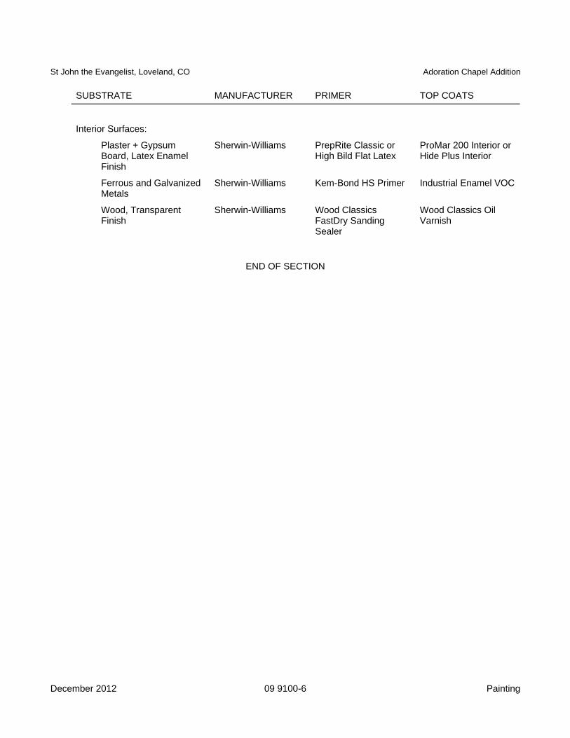
St John the Evangelist, Loveland, CO Adoration Chapel Addition
December 2012 09 9100-6 Painting
SUBSTRATE MANUFACTURER PRIMER TOP COATS
Interior Surfaces:
Plaster + Gypsum Board, Latex Enamel Finish
Sherwin-Williams PrepRite Classic or High Bild Flat Latex
ProMar 200 Interior or Hide Plus Interior
Ferrous and Galvanized Metals
Sherwin-Williams Kem-Bond HS Primer Industrial Enamel VOC
Wood, Transparent Finish
Sherwin-Williams Wood Classics FastDry Sanding Sealer
Wood Classics Oil Varnish
END OF SECTION

St John the Evangelist, Loveland, CO Adoration Chapel Addition
January 2013 10 1423-1 Interior Panel Signs
SECTION 10 1423
INTERIOR PANEL SIGNS PART 1 GENERAL 1.1 SUMMARY
A. Section Includes: 1. Plastic interior panel signs.
B. Related Sections:
1. Division 01: Administrative, procedural, and temporary work requirements. 1.2 SUBMITTALS
A. Submittals for Review: 1. Shop Drawings: Include sign locations, sizes, mounting heights, available colors and content.
1.3 QUALITY ASSURANCE
A. Conform to applicable accessibility code for sign design, construction, location, and mounting height. PART 2 PRODUCTS 2.1 MATERIALS
A. Signs: 1. Type: Melamine plastic laminate with contrasting color core, non-static, fire retardant, matte
finish. 2. Thickness: [1/8] inch. 3. Face and core colors: To be selected from manufacturer's full color range.
2.2 ACCESSORIES
A. Adhesive: 1. Type recommended by sign manufacturer.
2.3 FABRICATION
A. Fabricate signs by reverse engraving process to produce characters and graphics in contrasting color, raised [1/32] inch.
B. Characters:
1. Height: [5/8] inch. 2. Style: Sans serif style to be selected, upper case. 3. Width to height ratio: Between [3:5 and 1:1.] 4. Stroke width to height ratio: Between [1:5 and 1:10.]
C. Pictograms: Universal accessibility symbols, [6] inches high.
D. Provide Braille indications for each character.
E. Corners: Square.
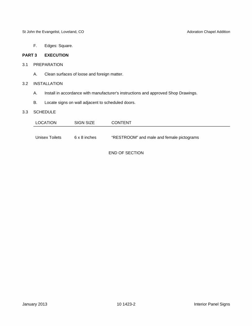
St John the Evangelist, Loveland, CO Adoration Chapel Addition
January 2013 10 1423-2 Interior Panel Signs
F. Edges: Square.
PART 3 EXECUTION 3.1 PREPARATION
A. Clean surfaces of loose and foreign matter. 3.2 INSTALLATION
A. Install in accordance with manufacturer's instructions and approved Shop Drawings.
B. Locate signs on wall adjacent to scheduled doors. 3.3 SCHEDULE
LOCATION SIGN SIZE CONTENT
Unisex Toilets 6 x 8 inches “RESTROOM” and male and female pictograms
END OF SECTION
St John the Evangelist, Loveland, CO Adoration Chapel Addition
January 2013 10 2813-1 Toilet Accessories
SECTION 10 2813
TOILET ACCESSORIES PART 1 GENERAL 1.1 SUMMARY
A. Section Includes: 1. Toilet accessories. 2. Framed mirrors.
B. Related Sections:
1. Division 01: Administrative, procedural, and temporary work requirements. 1.2 REFERENCES
A. ASTM International (ASTM): 1. A123/A123M - Standard Specification for Zinc (Hot-Galvanized) Coatings on Iron and Steel
Products. 2. A269 - Standard Specification for Seamless and Welded Austenitic Stainless Steel Tubing for
General Service. 3. A666 - Standard Specification for Annealed or Cold-Worked Austenitic Stainless Steel Sheet,
Strip, Plate, and Flat Bar. 4. A1008/A1008M - Standard Specification for Steel, Sheet, Cold-Rolled, Carbon, Structural,
High-Strength Low-Alloy and High-Strength Low-Alloy with Improved Formability. 5. B456 - Standard Specification for Electrodeposited Coatings of Copper Plus Nickel Plus
Chromium and Nickel Plus Chromium. 6. C1036 - Standard Specification for Flat Glass.
1.3 SUBMITTALS
A. Submittals for Review: 1. Product Data:
a. Schedule accessories by room; show plans and elevations, and identify room name and number, type and quantity of accessories, and mounting heights.
b. Include manufacturer's brochures showing sizes, details of function, finishes, and attachment methods.
2. Warranty: Sample warranty form. 1.4 QUALITY ASSURANCE
A. Conform to ANSI A117.1 2009 for locating accessories. 1.5 WARRANTIES
A. Furnish manufacturer’s 15 year warranty providing coverage against mirror silver spoilage. PART 2 PRODUCTS 2.1 MANUFACTURERS
A. Design Basis: Contract Documents are based on products by Bradley Corp www.bradleycorp.com).
B. Equivalent products by following manufacturers are acceptable: 1. A and J Washroom Accessories. (www.ajwashroom.com) 2. American Specialties, Inc. (www.americanspecialties.com) 3. Bobrick Washroom Equipment, Inc. (www.bobrick.com)
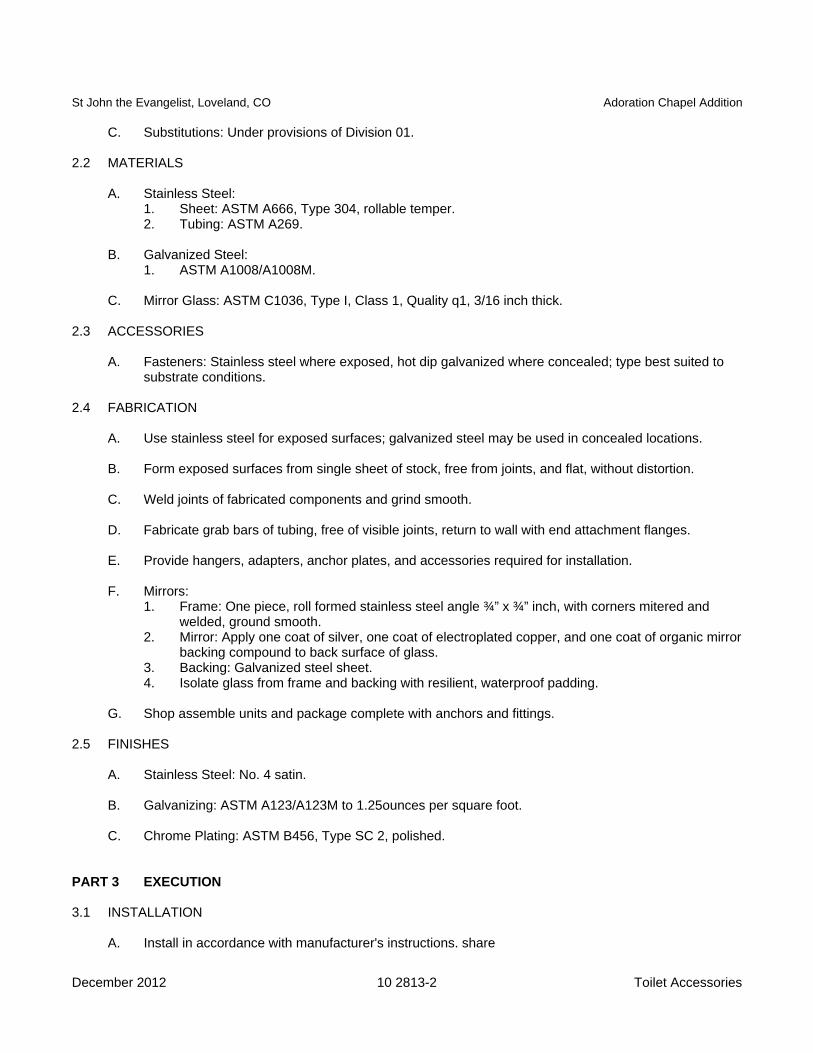
St John the Evangelist, Loveland, CO Adoration Chapel Addition
December 2012 10 2813-2 Toilet Accessories
C. Substitutions: Under provisions of Division 01.
2.2 MATERIALS
A. Stainless Steel: 1. Sheet: ASTM A666, Type 304, rollable temper. 2. Tubing: ASTM A269.
B. Galvanized Steel:
1. ASTM A1008/A1008M.
C. Mirror Glass: ASTM C1036, Type I, Class 1, Quality q1, 3/16 inch thick. 2.3 ACCESSORIES
A. Fasteners: Stainless steel where exposed, hot dip galvanized where concealed; type best suited to substrate conditions.
2.4 FABRICATION
A. Use stainless steel for exposed surfaces; galvanized steel may be used in concealed locations.
B. Form exposed surfaces from single sheet of stock, free from joints, and flat, without distortion.
C. Weld joints of fabricated components and grind smooth.
D. Fabricate grab bars of tubing, free of visible joints, return to wall with end attachment flanges.
E. Provide hangers, adapters, anchor plates, and accessories required for installation.
F. Mirrors: 1. Frame: One piece, roll formed stainless steel angle ¾” x ¾” inch, with corners mitered and
welded, ground smooth. 2. Mirror: Apply one coat of silver, one coat of electroplated copper, and one coat of organic mirror
backing compound to back surface of glass. 3. Backing: Galvanized steel sheet. 4. Isolate glass from frame and backing with resilient, waterproof padding.
G. Shop assemble units and package complete with anchors and fittings.
2.5 FINISHES
A. Stainless Steel: No. 4 satin.
B. Galvanizing: ASTM A123/A123M to 1.25ounces per square foot.
C. Chrome Plating: ASTM B456, Type SC 2, polished. PART 3 EXECUTION 3.1 INSTALLATION
A. Install in accordance with manufacturer's instructions. share
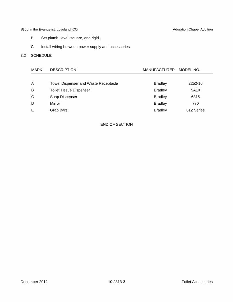
St John the Evangelist, Loveland, CO Adoration Chapel Addition
December 2012 10 2813-3 Toilet Accessories
B. Set plumb, level, square, and rigid.
C. Install wiring between power supply and accessories.
3.2 SCHEDULE
MARK DESCRIPTION MANUFACTURER MODEL NO.
A Towel Dispenser and Waste Receptacle Bradley 2252-10
B Toilet Tissue Dispenser Bradley 5A10
C Soap Dispenser Bradley 6315
D Mirror Bradley 780
E Grab Bars Bradley 812 Series
END OF SECTION

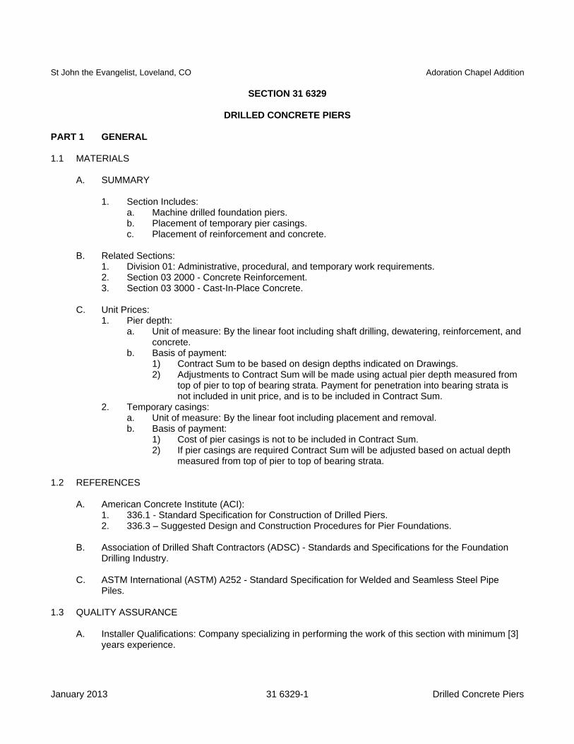
St John the Evangelist, Loveland, CO Adoration Chapel Addition
January 2013 31 6329-1 Drilled Concrete Piers
SECTION 31 6329
DRILLED CONCRETE PIERS PART 1 GENERAL 1.1 MATERIALS
A. SUMMARY
1. Section Includes: a. Machine drilled foundation piers. b. Placement of temporary pier casings. c. Placement of reinforcement and concrete.
B. Related Sections:
1. Division 01: Administrative, procedural, and temporary work requirements. 2. Section 03 2000 - Concrete Reinforcement. 3. Section 03 3000 - Cast-In-Place Concrete.
C. Unit Prices:
1. Pier depth: a. Unit of measure: By the linear foot including shaft drilling, dewatering, reinforcement, and
concrete. b. Basis of payment:
1) Contract Sum to be based on design depths indicated on Drawings. 2) Adjustments to Contract Sum will be made using actual pier depth measured from
top of pier to top of bearing strata. Payment for penetration into bearing strata is not included in unit price, and is to be included in Contract Sum.
2. Temporary casings: a. Unit of measure: By the linear foot including placement and removal. b. Basis of payment:
1) Cost of pier casings is not to be included in Contract Sum. 2) If pier casings are required Contract Sum will be adjusted based on actual depth
measured from top of pier to top of bearing strata. 1.2 REFERENCES
A. American Concrete Institute (ACI): 1. 336.1 - Standard Specification for Construction of Drilled Piers. 2. 336.3 – Suggested Design and Construction Procedures for Pier Foundations.
B. Association of Drilled Shaft Contractors (ADSC) - Standards and Specifications for the Foundation
Drilling Industry.
C. ASTM International (ASTM) A252 - Standard Specification for Welded and Seamless Steel Pipe Piles.
1.3 QUALITY ASSURANCE
A. Installer Qualifications: Company specializing in performing the work of this section with minimum [3] years experience.
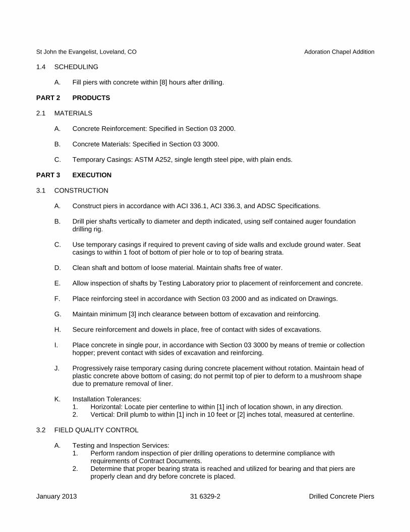
St John the Evangelist, Loveland, CO Adoration Chapel Addition
January 2013 31 6329-2 Drilled Concrete Piers
1.4 SCHEDULING
A. Fill piers with concrete within [8] hours after drilling. PART 2 PRODUCTS 2.1 MATERIALS
A. Concrete Reinforcement: Specified in Section 03 2000.
B. Concrete Materials: Specified in Section 03 3000.
C. Temporary Casings: ASTM A252, single length steel pipe, with plain ends. PART 3 EXECUTION 3.1 CONSTRUCTION
A. Construct piers in accordance with ACI 336.1, ACI 336.3, and ADSC Specifications.
B. Drill pier shafts vertically to diameter and depth indicated, using self contained auger foundation drilling rig.
C. Use temporary casings if required to prevent caving of side walls and exclude ground water. Seat
casings to within 1 foot of bottom of pier hole or to top of bearing strata.
D. Clean shaft and bottom of loose material. Maintain shafts free of water.
E. Allow inspection of shafts by Testing Laboratory prior to placement of reinforcement and concrete.
F. Place reinforcing steel in accordance with Section 03 2000 and as indicated on Drawings.
G. Maintain minimum [3] inch clearance between bottom of excavation and reinforcing.
H. Secure reinforcement and dowels in place, free of contact with sides of excavations.
I. Place concrete in single pour, in accordance with Section 03 3000 by means of tremie or collection hopper; prevent contact with sides of excavation and reinforcing.
J. Progressively raise temporary casing during concrete placement without rotation. Maintain head of
plastic concrete above bottom of casing; do not permit top of pier to deform to a mushroom shape due to premature removal of liner.
K. Installation Tolerances:
1. Horizontal: Locate pier centerline to within [1] inch of location shown, in any direction. 2. Vertical: Drill plumb to within [1] inch in 10 feet or [2] inches total, measured at centerline.
3.2 FIELD QUALITY CONTROL
A. Testing and Inspection Services: 1. Perform random inspection of pier drilling operations to determine compliance with
requirements of Contract Documents. 2. Determine that proper bearing strata is reached and utilized for bearing and that piers are
properly clean and dry before concrete is placed.
St John the Evangelist, Loveland, CO Adoration Chapel Addition
January 2013 31 6329-3 Drilled Concrete Piers
3. Notify Architect if soil or water conditions require casing of piers. 4. Inspection reports of pier drilling shall contain following:
a. Pier mark. b. Shaft diameter. c. Pier depth calculated from finish floor elevation. d. Depth of penetration into bearing strata. e. Plumbness deviation. f. Lateral deviation at top of pier. g. Description of unusual conditions encountered, including ground water. h. Casing requirements. i. Reinforcing placed, including dowels. j. Deviations from Contract Document requirements.
END OF SECTION

St John the Evangelist, Loveland, CO Adoration Chapel Addition
January 2013 32 1313-1 Concrete Paving
SECTION 32 1313
CONCRETE PAVING PART 1 GENERAL 1.1 SUMMARY
A. Section Includes: 1. Concrete gutters and walks.
B. Related Sections:
1. Division 01: Administrative, procedural, and temporary work requirements. 2. Section 03 3000 - Cast-In-Place Concrete. 3. Section 07 9200 - Joint Sealers.
1.2 REFERENCES
A. ASTM International (ASTM) D1752 - Standard Specification for Preformed Sponge Rubber and Cork Expansion Joint Fillers for Concrete Paving and Structural Construction.
PART 2 PRODUCTS 2.1 MATERIALS
A. Formwork: 1. Specified in Section 03 1000. 2. Metal Forms: Free of deformities, furnished in maximum practical lengths. 3. Wood Forms: Good grade lumber, sound and free of warp, minimum [2] inch nominal thickness
except where radii of curves require thinner forms.
B. Reinforcement: 1. Specified in Section 03 2000. 2. Dowels: Plain round bar dowels, conforming to reinforcing steel requirements.
C. Concrete Materials: Specified in Section 03 3000.
2.2 ACCESSORIES
A. Low VOC Liquid Release Agent: Colorless, odorless liquid formulated to break the bond between imprinting tools and surface of color-hardened concrete. VOC content less than 450 g/L (3.75lb/gal).
B. Waterborne Curing Compound and Sealer: Low VOC waterborne modified acrylic formulation.
Complies with ASTM C 309.
C. Joint Filler: [Non asphaltic type, ASTM D1752 with removable strip providing recess for joint sealer]
D. Joint Sealers: Specified in Section 07 9200. PART 3 EXECUTION 3.1 CONSTRUCTION OF FORMS
A. Construct formwork in accordance with Section 03 1000.
St John the Evangelist, Loveland, CO Adoration Chapel Addition
January 2013 32 1313-2 Concrete Paving
B. Set forms accurately to required grades and alignment.
C. Brace forms to withstand loads applied during concrete placement.
D. Install flexible or curved forms of wood or metal for curves with radius of 300 feet or less.
E. Leave forms in place for minimum [12] hours after completion of finishing operation.
F. Provide expansion joints where paving abuts other construction.
1. Shape joint filler to concrete cross section and fasten in place. 2. Provide holes for dowel bars maximum [1/8] inch larger than bar diameter. 3. Use removable strips to provide recess for sealant.
3.2 PLACING REINFORCING
A. Install reinforcement in accordance with Section 03 2000.
B. Place reinforcing in middle third of flatwork.
C. Stop alternate bars of reinforcing steel at control joints. 3.3 PLACING CONCRETE
A. Place concrete in accordance with Section 03 3000.
B. Place concrete continuously between predetermined expansion and control joints. Do not interrupt successive placement such that cold joints occur.
C. Shape curbs and gutters to cross section indicated on Drawings.
D. Strike off flatwork with screed, then float to uniform surface.
E. For surfaces not receiving imprinted/textured finish, provide [broom] finish in accordance with Section
03 3500.
F. Tool expansion joint edges and other exposed edges to smooth, dense surface with [1/8] inch radius.
G. Provide [tooled] control joints at [maximum 12 feet on center.]
H. Installation Tolerances: Surfaces true to plane, in longitudinal direction to required grade, within plus or minus [1/4] inch in 10 feet, noncumulative.
3.4 CONCRETE SEALING
A. Prior to sealing, the following conditions must be present:
1. Release agent has been removed. 2. Moisture content of concrete is low enough that alkali and other salts do not become trapped
beneath sealer. This will require a minimum of 28 days subsequent to concrete placement, or longer if required.
3. No evidence of free water on concrete surfaces to receive curing and sealing compound.
St John the Evangelist, Loveland, CO Adoration Chapel Addition
January 2013 32 1313-3 Concrete Paving
B. Seal imprinted concrete with liquid membrane curing and sealing compounds as recommended by manufacturer.
C. Seal expansion and control joints as specified in Section 07 9200.
3.5 SCHEDULE
A. Entry Slab: Imprinted/Textured, Colored Concrete B. Drainage pans: Colored Concrete
C. Replacement Sidewalks: No color, Broom Finish
END OF SECTION
St John the Evangelist, Loveland, CO Adoration Chapel Addition
January 2013 32 9223-1 Sodding
SECTION 32 9223
SODDING
PART 1 GENERAL 1.1 SUMMARY
A. Section Includes: 1. Sod installation. 2. Maintenance.
B. Related Sections:
1. Division 01: Administrative, procedural, and temporary work requirements. 1.2 REFERENCES
A. Turfgrass Producers International (TPI) - Guideline Specifications to Sodding. 1.3 SUBMITTALS
A. Quality Control Submittals: 1. Submit certification for grass species and sod source.
1.4 QUALITY ASSURANCE
A. Sod: Minimum age of [18] months, with root development that will support its own weight without tearing, when suspended vertically by holding upper two corners.
B. Sod Producer: Company specializing in sod production and harvesting with minimum [3] years
experience. 1.5 DELIVERY, STORAGE AND HANDLING
A. Deliver sod in rolls. Protect exposed roots from dehydration. C. Do not deliver more sod than can be installed within [24] hours.
B. Deliver fertilized in waterproof bags showing weight, chemical analysis, and name of manufacturer. PART 2 PRODUCTS 2.1 MATERIALS
A. Sod: 1. ASPA approved, field grown grade; cultivated grass sod, strong fibrous root system, free of
stones, burned or bare spots; containing no more than [5] weeds per [1000] square feet. 2.2 ACCESSORIES
A. Water: Clean, fresh and free of substances or matter which could inhibit vigorous growth of grass. 2.3 HARVESTING SOD
A. Machine cut sod in accordance with ASPA Guidelines.
St John the Evangelist, Loveland, CO Adoration Chapel Addition
January 2013 32 9223-2 Sodding
B. Cut sod in area not exceeding [1] square yard, with minimum [1/2] inch and maximum [1] inch topsoil base.
PART 3 EXECUTION 3.1 PREPARATION
A. Prepare subsoil; eliminate uneven areas and low spots.
B. Remove foreign materials and undesirable plants and their roots. Do not bury foreign material beneath areas to be sodded.
C. Remove contaminated topsoil.
3.2 LAYING SOD
A. Moisten prepared surface immediately prior to laying sod.
B. Lay sod within [24] hours after harvesting to prevent deterioration.
C. Lay sod tight without open joints and without overlapping; stagger end joints [12] inches minimum. Do not stretch sod pieces.
D. Lay smooth.
E. Place top elevation of sod [1/2] inch below adjoining edging, paving and curbs.
F. On slopes [1:2] and steeper, lay sod perpendicular to slope and secure every row with wooden pegs
at maximum [2] feet on center. Drive pegs flush with soil portion of sod.
G. Immediately after installation, roll sod; remove air pockets, voids, and minor depressions and irregularities.
H. Fill voids between sod pieces with topsoil. Rake excess topsoil into sod but do not smother grass with
topsoil. 3.3 WATERING
A. Water sodded areas within [2] hours after installation, to saturation.
B. Continue watering daily using less water; ensure moisture to [4] inch depth but avoid standing water.
C. When root growth is observed by lifting corners of sod, reduce watering to alternating days.
D. After [14] days, if root growth prevents sod corners from being lifted, allow sod to dry to permit mowing.
3.4 MAINTENANCE
A. Maintain lawn areas by watering, mowing, and weeding from date of installation until Substantial Completion.
END OF SECTION

Basis Architecture TOC - 1 St. John’s Adoration Chapel Addition RJM: 12106: January 31, 2013
DIVISION 16000
ELECTRICAL SPECIFICATION
TABLE OF CONTENTS
SECTION 16010 .................................................................................... GENERAL PROVISIONS SECTION 16100 .............................................................. BASIC MATERIALS AND METHODS SECTION 16102 ............................................................. NAMEPLATE AND WARNING SIGNS SECTION 16103 .......................................................................... EMPTY RACEWAY SYSTEMS SECTION 16400 .................................................................................... ELECTRICAL SYSTEMS SECTION 16410 ........................................................................................ EXTERIOR LIGHTING SECTION 16900 ............................................................................ ELECTRICAL COMPLETION
Basis Architecture 16010 - 1 St. John’s Adoration Chapel Addition RJM: 12106: January 31, 2013
SECTION 16010
GENERAL PROVISIONS
PART 1 - GENERAL 1.1 CONDITIONS
A. All work under this Section shall be governed by project general conditions, along
with all supplements and amendments thereto, as published by Architect. 1.2 CODES AND REGULATIONS
A. Comply with all applicable state and local codes, regulations and ordinances, and the latest applicable requirements of the National Electrical Code (NEC) of the NFPA, as interpreted by the local inspection authority who shall have final jurisdiction.
B. Comply also with all OSHA requirements and directives.
1.3 EXAMINATION OF PREMISES
A. Examine the premises prior to bidding and become fully familiar with existing conditions.
1.4 PERMITS
A. Secure and pay for all permits, fees, taxes, licenses and inspections in connection with the electrical work.
1.5 DRAWINGS AND SPECIFICATIONS
A. Drawings are diagrammatic and indicate general arrangement of electrical work. Locations are approximate and shall be subject to minor modifications as directed by Architect and/or Engineer.
B. Contractor shall be responsible for exact fitting of all materials, equipment, etc., in building. All dimensions shall be verified on the job.
C. Refer to Architectural, Structural, and Mechanical Drawings and Specifications, as part of this set, and be responsible for all information contained therein as affects the electrical work.
D. Instructions such as "provide..." shall mean "Contractor shall be responsible for the furnishing and installing of new..., complete in every respect."
Basis Architecture 16010 - 2 St. John’s Adoration Chapel Addition RJM: 12106: January 31, 2013
1.6 ROOM NAMES
A. Contractor is responsible to coordinate with General Contractor to obtain actual room names and numbers, designated by Owner. Actual room names and numbers shall be used on all panel schedules, computer programming, graphic plaques, sound systems, telephone system, intercoms, fire alarms, security systems and similar.
1.7 30-DAY AMMETER TEST REQUIREMENTS
A. Electrical contractor shall hire a qualified third party testing agency that specializes in associated work such as ERS (Electrical Reliability Services) to perform 30 day ammeter tests in accordance with NEC 220.87. Recordings shall be stored electronically and reported to the engineer electronically in a format compatible with Microsoft Excel. Electrician shall provide engineer with the actual maximum demand values (per NEC 220.87) for each feeder, in addition to the electronic data. Ammeter tests shall be performed on all three phases for the feeders indicated on the drawings.
B. Recordings shall be coordinated with owner to minimize recording during periods of when the facility is not operating under “typical” conditions.
C. Recordings shall be emailed to engineer (provide one “.xls” file per recording) and include a summary indicating all information outlined below for each ammeter test called for on the drawings:
1. Feeder (equipment fed from/to): 2. Size and type of OCPD's at each end of feeder: 3. Phase conductor size and insulation type: 4. Neutral Conductor size and insulation type: 5. Ground Size and insulation type: 6. Conduit size and type: 7. Number of parallel runs: 8. Date Time test began and ended: 9. Maximum (per NEC 220.87) - amperage recorded on each phase:
D. Meter used shall be designed specifically to make recordings in accordance with NEC 220.87 requirements.
E. Firm performing study is responsible for interpretation of test results and their
applicability to NEC 220.87 requirements. 1.8 COMPUTER FILE RELEASE
A. Complete attached required form and fee for use of Computer Files.
Basis Architecture 16010 - 3 St. John’s Adoration Chapel Addition RJM: 12106: January 31, 2013
COMPUTER FILE RELEASE R.J. McNutt & Associates, Inc., the electrical engineering consultant (the Engineer), has agreed to provide electronic drawing files, containing computer generated information to: (Hereinafter called the User) For the Project known as: For the Bid Package known as: XXX, CD's For Drawings in the following Series: EXX through EYY
These files are provided subject to the following conditions: 1. The Engineers are authors of the Drawings, Specifications and other documents prepared by them for this Project, and holds the
copyright therein, subject to the terms of the Agreement between the Engineer-Architect, the Architect-Owner. Any copying of these files by the User is at their own risk.
2. These files have been prepared to conform to the specifications set forth in said Agreements and may not run accurately on other
equipment software. 3. These files have been transmitted on a readable compact disk (CD) to avoid alteration by the User. User shall maintain CD in its
original condition without modification for six years after completion of project. 4. It is understood that these files do not contain record documents and therefore do not necessarily reflect as-built conditions. 5. It is understood that these files only contain data prepared by the Engineer and may not included data prepared by other project
Consultants, ie: Architectural backgrounds. Data prepared by other project Consultants may have to be obtained separately from the design Consultant. It is also understood that the building is still subject to design revisions that could alter the electrical drawings. Accuracy of information included, that has been prepared by other project Consultants, is not guaranteed and may not be the most current.
6. The cost for these files is: $75.00 per sheet, payable to the Engineer prior to release of the files from the Engineer. The cost of updates
of files supplied is: $75.00 per sheet, payable to the Engineer prior to release of the files from the Engineer. 7. At the User's request, the Engineer can furnish traditionally prepared hard copies of the files at a cost. In the event of any conflict
between the hard copies and the files, the contents of the hard copy shall govern. 8. The Engineer reserves the right to remove its name, the Architects name, title block, professional seal and all other evidence of
authorship from any files, including without limitation, Drawings and Specifications, submitted in electronic form. 9. The User shall release, indemnify and defend the Engineer, its officers, employer and Architect from and against all liability arising
out of changes to the Engineer's electronic data made by the User or by anyone to whom the User has released such data.
ACCEPTED: COMPANY: ________________________________________ (SIGNATURE) BY: DATE: _________________________________________ (PRINTED NAME)
Basis Architecture 16010 - 4 St. John’s Adoration Chapel Addition RJM: 12106: January 31, 2013
PART 2 - PRODUCTS 2.1 STANDARDS
A. All material shall be new and shall be listed by Underwriters Laboratories Incorporated (UL listed) for the purpose intended and shall bear the UL label. Damaged or defective materials shall be replaced. All materials shall comply with the latest NEMA standards.
PART 3 - EXECUTION 3.1 SHOP DRAWINGS
A. Furnish electronic (pdf) sets of Shop Drawings to Architect for the following:
1. Lighting Equipment. 2. Distribution Equipment. 3. Fire Alarm.
B. All materials and equipment shall be approved prior to beginning work.
C. Receipt within 30 days after award of contract.
D. Shop Drawings, including:
1. Dimensions and detail. 2. Floor plan wiring diagrams showing routing, zones, wire quantity, and
field connections. 3. Catalog data specifically for equipment to be used. 4. Maintenance data. 5. See shop drawing requirements in General Provisions. 6. If more than 5 sets are required by Contractor, Electrical Contractor shall
provide Sepia reproducible so they can copy additional sets. Only the 5 sets required in 3.01-A will be reviewed.
E. Electrical Contractor shall provide shop drawing approval stamps on all equipment supplied by them prior to Engineer's shop drawing approval. Electrical Contractor to check for conformance with the design of the project and compliance with the information given in the contract documents. Contractor is responsible for dimensions which shall be confirmed and correlated at the job site; fabrication process and techniques of construction.
3.2 RECORD DRAWINGS
A. Maintain a complete set of Electrical Drawings at the job site with all changes in the work marked thereon in a contrasting color.

Basis Architecture 16010 - 5 St. John’s Adoration Chapel Addition RJM: 12106: January 31, 2013
B. Electrical Contractor shall provide architect at completion of project a complete set of Record drawings showing all changes in work marked there on including all system wiring diagrams.
3.3 COORDINATION
A. Order the progress of the work so as to conform to the progress of other trades. Coordinate all electrical installations and rough-ins as required.
3.4 WORKMANSHIP
A. Provide a competent foreman on the job at all times. All work shall be accomplished in a manner which is neat, workmanlike, of first quality, and compatible with good commercial practices and standards. Provide competent workmen who are skilled as electricians.
3.5 INSTALLATION
A. Install all equipment and materials in accordance with information as indicated on Drawings and in full accord with Manufacturer's recommendations.
3.6 CUTTING AND PATCHING
A. Provide all cutting, channeling, chasing, drilling, etc., operations as may be required for electrical work. In general, all such operations shall be held to a minimum.
B. All patching and painting shall be done by Contractor. 3.7 CONSTRUCTION POWER AND LIGHTING
A. Provide construction power and lighting for construction as required. Energy costs will be paid by Contractor. All temporary facilities shall be properly grounded, shall comply with NEC and OSHA requirements, and shall have ground fault protection.
3.8 TRENCHING AND BACKFILL
A. Be responsible for all trenching and backfill for electrical work. Backfilling shall be done in accordance with Architectural Specifications. Be responsible for all new and existing buried utilities.
B. Electrical Contractor shall locate all onsite and offsite utilities prior to any trenching or excavation done by any trade to locate utilities in areas where construction is to be performed.
Basis Architecture 16010 - 6 St. John’s Adoration Chapel Addition RJM: 12106: January 31, 2013
3.9 SECONDARY SERVICE - EXISTING
A. Existing power for distribution within the building is underground, from the secondary side of padmount transformer supplied by the local utility company. This service is 3-phase, 4-wire, 120/208 volt, 60 Hertz alternating current for normal power and lighting requirements. Verify these requirements with the local public utility. General arrangement of the service equipment is shown on Drawings. Equipment shall be as specified herein. Provide all coordination with utility company as required. Notify Architect or Engineer if characteristics or point of attachment are different than that shown on Drawings.
3.10 TELEPHONE AND CATV SERVICE - EXISTING 3.11 UTILITY SERVICES (Power)
A. All costs levied by the serving Utility for electrical and telephone service on the project will be paid by the Owner.
3.12 GUARANTEE
A. Guarantee all materials, labor, workmanship and successful operation of all equipment installed under this contract for a period of one year from date of final acceptance. Repair or replace, at no expense to Owner, all defects which may arise during this time due to inferior or defective materials, equipment, or workmanship.
3.13 SUBSTITUTIONS
A. The intent of Specifications is to establish quality standards of materials and equipment installed. Specific items are identified by Manufacturer, trade name or catalog designation. Should Contractor propose to furnish materials and equipment other than those specified as permitted by "or approved equal" clauses, he shall submit a written request in duplicate, at least seven calendar days prior to bidding date, for any or all substitutions to Architect. Substitutions submitted for approval shall list items as specified with the alternate substitution.
B. Where substitutions alter the design, conduit, wiring or space requirements indicated on Drawings, Contractor shall include items of cost for the revised design and construction.
C. Substitutions sent by Fax Machine or e-mail will not be acceptable and will not be reviewed.
D. Substitutions of light fixtures shall include photometric studies of areas proposed for substitutions, i.e. exterior building and parking lots, special areas inside building as directed by Engineer.
Basis Architecture 16010 - 7 St. John’s Adoration Chapel Addition RJM: 12106: January 31, 2013
3.14 OUTAGES
A. Coordinate all electrical service outages with Owner and General Contractor. Plan all work so that duration of outage is kept to an absolute minimum. Provide temporary wiring as necessary and as required in order to maintain continuous service for Owner's operation where outage must be accomplished during a time when power is deemed necessary by Owner, or when outage is to be of an extended duration, maximum 6 hours. All outage time and scheduling of same shall be as approved by Owner and shall conform to Owner's schedules.
3.15 DELIVERY AND STORAGE OF MATERIALS
A. Make provisions for delivery and safe storage of all materials and make the required arrangements with other Contractors on the job for the introduction into the building of equipment too large to pass through finished openings.
B. Where materials are indicated to be furnished by others to Contractor for installation, these materials shall be checked and their delivery properly receipted. Assume full responsibility for the storage and safe keeping of said materials from time of delivery until final acceptance.
C. All NEMA 1 rated equipment shall be stored in clean dry location such as trailers or enclosed dry areas of buildings, and etc. Such equipment shall include, but not be limited to, panelboards, switchboards, dry type transformers, conductors, light fixtures, special system equipment, devices, and etc.
3.16 AVAILABLE TO OWNER
A. Electrical Contractor shall be available to Owner for additional hook up to lights, equipment, etc., on time and material.
3.17 ACCESS PANELS
A. Access panels required by the Electrical Contractor shall be provided by the Electrical Bid Contractor then turned over to the appropriate trade for installation.
3.18 DRAWING/SPECIFICATION CONFLICTS
A. In the event of conflict between the Drawings and the Specifications, the more stringent requirement will apply. When a conflict occurs notify Engineer in writing for clarification.
3.19 REMODEL WORK
A. Electrical Contractor shall remove all wiring devices, light fixtures, etc., which are indicated to be removed. In general, symbols which are dotted indicate
Basis Architecture 16010 - 8 St. John’s Adoration Chapel Addition RJM: 12106: January 31, 2013
existing devices which are to remain. Symbols which are dotted and which are slashed through indicate existing devices which are to be removed. Devices which are to be removed may require reworking conduit and wiring in order to maintain service to other devices. If removed devices are on walls or ceilings which are to remain, blank coverplates are to be installed on outlet boxes.
B. Where remodeling interferes with circuits in areas which are otherwise undisturbed, circuits shall be reworked as required.
C. Existing devices and circuiting which are shown are indicated only for informational purposes. Electrical Contractor shall visit the site and shall verify conditions as they exist and shall remove, relocate and/or rework any electrical equipment or circuits affected (whether indicated or not) due to removal or reworking of existing walls, ceilings, etc. Electrical Contractor shall familiarize himself with all work to be done by other trades by studying Architectural, Structural, Mechanical and Plumbing Drawings.
D. Coordinate routing of all conduits with Mechanical and Plumbing Contractors in order to avoid conflicts with ducts, pipes, etc.
E. All equipment, fixtures, devices, etc., which are removed shall be delivered to Owner for disposition. All items which are removed and not wanted by Owner and which are not reused shall become the property of Electrical Contractor and shall be removed from site.
F. The cost of cutting and patching necessary for the installation or removal of electrical work shall be included in the Electrical Contract. Coordinate with General Contractor.
G. Electrical Contractor shall remove and replace lighting fixtures; rework, relocate and replace conduit and wiring and do other work required by the installation of new ductwork, piping, etc., above existing ceiling. Coordinate with other Contractors and verify the extent of the work.
END OF SECTION 16010
Basis Architecture 16100 - 1 St. John’s Adoration Chapel Addition RJM: 12106: January 31, 2013
SECTION 16100
BASIC MATERIALS AND METHODS
PART 1 - GENERAL 1.1 STANDARDS
A. All materials shall be new, shall be UL listed for the purpose intended, and shall
bear the UL label. Damaged or defective materials shall be replaced. All materials shall comply with latest NEMA standards.
1.2 SUBSTITUTIONS 1.3 BALANCING
A. The complete system shall be load balanced to within 10 to 15 percent per phase.
1.4 PHASE ROTATION
A. Electrical Contractor shall assure and be responsible for proper phase rotation of
all motors, compressors, and other three phase equipment prior to energizing equipment.
B. Electrical Contractor shall be responsible and coordinate proper phase rotation
connections made by the serving utility company prior to energizing main service equipment.
PART 2 - PRODUCTS
2.1 MAIN DISTRIBUTION SWITCHBOARD - FUSIBLE (MDP) - EXI STING 2.2 LOADCENTERS
A. Provide loadcenter type distribution panelboards unless specifically indicated otherwise. All panels shall have a flush, steel hinged door and shall have quantities and sizes of plug-in, thermal-magnetic, full width circuit breakers as indicated. All two and three pole breakers shall have a common internal "trip free" mechanism and a common operating handle. Loadcenters shall have master key locks, copper phase, neutral and ground bar. Loadcenters shall be GE type or equal by Square D, Cutler Hammer or Siemens.
B. Panelboards shall be series rated.
Basis Architecture 16100 - 2 St. John’s Adoration Chapel Addition RJM: 12106: January 31, 2013
2.3 SAFETY SWITCHES
A. Provide fusible and non-fusible heavy duty type disconnect switches where shown and required. Switches shall be horsepower rated, quick make and quick-break, by same manufacturer as loadcenter.
B. Each enclosure shall be NEMA type suitable for surrounding area and condition. Consult Mechanical Drawings and Specifications for their requirements.
C. Switches shall be equipped with rejection clips for Class "R" current limiting fuses.
D. Switches shall be same manufacturer as loadcenter. 2.4 FUSES
A. Provide sizes, classes and types of fuses as indicated for all fused safety switches. All fuses 0-600 amps shall have the Class "R" rejection feature. Verify actual load current of all motors prior to ordering fuses and provide fuses of sizes as recommended by Manufacturer. Generally, motor fuses shall be the dual element type and shall be set at 110 percent of full load amps, or 125 percent where required for heavy duty usage or high ambient temperatures. Fuses shall be the power voltage rating to match circuit characteristics in which installed. Fuses indicated on Drawings are those of Bussmann Co., equal by Gould Shawmut or Littel Fuse.
2.5 SPARE FUSES
A. Provide three spare fuses of each size and type installed. 2.6 NAMEPLATES
A. Provide 1" X 3" laminated plastic nameplates (1/4" high white letters; black background for normal power equipment, red background for emergency power equipment) for all switches, panelboards, controllers, etc., in main distribution switchboards and sub-distribution panelboards. Nameplates shall be permanently attached to equipment with two screws. Provide blank nameplates for all spares.
B. Multiple Gang Light Switches: Provide engraved coverplates 1/8" lettering black filled on all switch plates two and more ganged. Lettering shall indicate area served.
C. Light switches/receptacles (all): Provide panel and circuit Kroy labels on front of coverplate and label with marker on inside panel cover and circuit also.
D. Engrave Remote Smoke Duct Units: Provide phenolic engraved 1/8" lettering to white core. Lettering shall indicate mechanical unit served. Attach with screws.
Basis Architecture 16100 - 3 St. John’s Adoration Chapel Addition RJM: 12106: January 31, 2013
E. Engrave Manual Fan Shut Down Switches: Provide same phenolic tag as smoke duct unit nametags.
F. Label all mechanical equipment, safety switches, and starters, etc., with raised letter tape. Nameplates and labels shall indicate the general areas and type of electrical load served by each circuit.
G. Neatly label all Junction box coverplates as to their function. Use a permanent ink pen. Labeling shall be lights, smoke detector power, elevator control, fire alarm, receptacles, etc. Labeling shall be done on J-boxes that are above accessible ceiling and in storage rooms and maintenance areas, etc. Do not label J-boxes in public view.
2.7 NM-NONMETALLIC SHEATHED CABLE – NOT ALLOWED ON THIS
PROJECT 2.8 CONDUCTORS
A. Provide a complete system of conductors for all raceway systems. All conductors shall be rated 600V, and shall be of a manufacturer subscribing to applicable IPCEA and NEMA standards and practices. Conductors shall be of sizes and types as indicated, and as required by NEC for specific uses. Where quantities of conductors in a raceway system are not specifically indicated, provide number as required to maintain function, control and number of circuits as indicated. All conductors shall be UL listed and approved, and shall conform to the following:
1. Minimum wire size shall be #12 AWG copper except for control or signal
circuits, which may be #14 AWG copper. 2. Unless otherwise indicated, all wiring for branch circuits shall be copper
#12 AWG in 1/2" conduit, protected by 20 ampere circuit breakers. See Voltage Drop.
3. Voltage Drop: If distance from panel to first outlet is 75 feet or greater (for 120V circuits) #10 shall be installed from circuit breaker to every device in circuit.
4. Wire sizes #10 AWG copper and smaller shall be solid; #8 AWG copper and larger shall be stranded.
B. The following insulation standards shall apply:
1. All feeder and service conductors shall be type THWN, XHHW or RHW. 2. Other conductors shall be per NEC THHN/THWN copper unless noted
otherwise, Article 310. 3. Type THWN copper for exterior runs in conduit.
C. Motor wiring for power shall be stranded.
D. Aluminum conductors shall not be used on this project.
Basis Architecture 16100 - 4 St. John’s Adoration Chapel Addition RJM: 12106: January 31, 2013
E. Conductor Neutral Applications:
1. Neutrals: Copper, same size as phase conductor, derating neutrals not allowed.
2. Provide separate neutral conductors for each 20 amp single pole breaker.
2.9 CONDUITS
A. Conduits shall be provided for all wiring runs as shown and specified. All sizes shall be per NEC. Use GRC where required by code, utility company, for mechanical protection and as shown. Type IMC may be used in lieu of GRC where permitted. Use EMT for all other runs. The use of AC (Armored Cable), MC (Metal Clad), or flexible conduit shall not be used for branch circuits or feeders (except for final connections to vibrating equipment - 36"). Provide approved couplings and connectors for all connections. Final connections to motors and other vibrating or rotating equipment shall be made in flexible conduit.
B. Heavywall, type II, rigid, Schedule 40 PVC:
1. For all wiring runs in or under the floor slab which is in contact with the ground.
2. For all wiring runs buried underground, unless otherwise indicated. 3. Do not use Schedule 40 or 80 PVC above ground. Conduit sizes 1" and
smaller use schedule 80 PVC elbows and conduit sizes 1 1/4" and larger use GRC tar coated elbows to max. 6" above grade then change to EMT conduit. Note: Provide expansion joints in accordance with Manufacturer's recommendations.
C. Use approved type couplings and connectors in all conduit runs and make all joints tight. Provide insulated bushings for all terminations in pipe size 1 1/4" and larger. Provide all steel set screw couplings and connectors for all other conduits. Provide expansion fitting and bonding conductors for all runs which cross building expansion joints. Provide waterproof steel compression gland couplings and connections for all runs in wet locations such as exposed to weather, buried in slabs, etc.
2.10 SURFACE RACEWAY
A. Steel .025 and .040 inch, buff finish. Ten foot lengths with coupling. One piece raceway system consists of separate base and removable cover sections. System shall be furnished complete with all appropriate sized fittings, J-boxes, and support hardware. Manufacturer Wiremold series 500 and 700 with all fittings.
Basis Architecture 16100 - 5 St. John’s Adoration Chapel Addition RJM: 12106: January 31, 2013
2.11 SUPPORTS AND HANGERS
A. Provide supports and hangers as necessary and as required to insure a good and substantial installation. Support raceways, fixtures, cabinets, boxes, etc., on approved types of trapeze hangers or wall brackets as manufactured by Unistrut or acceptable equal. Provide steel hanger rods securely fastened to or through the building structure for all trapezes, etc. Do not suspend from mechanical piping or ductwork. Perforated plumber's straps or wire will not be permitted.
B. Obtain Architect's approval for the use of powder-driven fasteners and use only in locations as he may direct.
C. Contractor shall not fasten, attach or hang any material from the roof deck. All conduits, junction boxes, fixtures, devices and equipment shall be hung from the structural steel frame and shall be placed with a minimum of 1" clearance below the roof deck. Wiring and conduits shall not be placed within the ribs of the roof deck. Contractor shall not loosen, remove or cut any roofing system fasteners protruding through the roof deck.
2.12 OUTLETS
A. Outlets shall be galvanized steel or zinc pressed steel outlet boxes for all locations except where otherwise indicated or where cast metal boxes are required by NEC. Boxes are to be 4" square or octagonal, 2 1/8" deep. Provide plaster or tile rings for all flush outlets installed where wood, drywall tile plaster, etc., types of finishes are applied. All outlets for exterior application shall be cast, weatherproof type, with gasket and case coverplate. Tile boxes of extra depth may be used for interior, dry applications where masonry block or brick walls constitute the finished wall surface. In any event, provide outlet boxes of proper type and design for the particular fixture or device to be installed. Boxes shall be as manufactured by Steel City or acceptable equal.
B. Surface mounted boxes shall be cast metal weatherproof, with grounding terminal, threaded hubs, and shall be similar and equal to Crouse-Hinds design Type FD or FS.
C. Pull Boxes: Provide pull boxes in raceway runs as required by NEC and job conditions. Install in accessible locations.
D. Surface Raceway: Surface raceway boxes same manufacturer as surface raceway. 2.13 LIGHTING EQUIPMENT
A. General: Provide all lighting equipment and lamps as shown on Drawings and as called for in these Specifications. Provide all such equipment fully complete and prewired. Install all equipment in a secure and substantial manner, and in full accord with Manufacturer's recommendations. Provide all such miscellaneous installation equipment such as support, hangers, yokes, flanges, etc., as is
Basis Architecture 16100 - 6 St. John’s Adoration Chapel Addition RJM: 12106: January 31, 2013
necessary. Provide 1 1/2" spacer, finished, factory-approved type, between tops of fluorescent fixtures and combustible ceiling materials as required by code. Provide for aiming of all adjustable lighting fixtures as directed by Architect; exterior fixtures shall be adjusted at night.
B. Fixtures (Luminaries): All fixtures exposed to weather or cold temperatures shall be weatherproof and suitable for efficient operation at temperatures and conditions concerned. All fixtures shall bear UL label for its particular application, or as indicated; 32 watt super T8 fluorescent shall be rapid start; 20 watt shall be trigger start. Install surface or pendant mounted luminaires true and straight. Provide plaster frames or similar type devices compatible with ceiling
C. Dual/three level lighting fixtures shall be provided with 4 wire flex and lead conductors.
D. HID ballasts shall be high power factor, Premium (CWA), energy savings, ETL CBM certified and labeled, Class P, Universal, Valmont, Advance or equal.
E. Electronic Ballasts:
1. Separate electronic ballasts shall be provided in order to provide dual/three level lighting as shown on plans.
2. Ballasts shall be compatible with T8 lamps, high power factor energy saving, electronic type.
3. Ballast shall bear the CBM, UL, and ETL labels certifying the ballasts comply with these specifications and standards.
4. Ballasts shall be "P" rated. 5. Ballast shall be one of the following: Sylvania electronic type.
F. Proper lamps shall be provided for all fixtures and shall bear Osram/Sylvania label. All incandescent lamps shall be rated for 130V operations.
1. Fluorescent lamps 4100K, CRI-80 or greater.
2.14 DEVICES AND PLATES
A. Switches: Provide the following flush switch devices where indicated and required. Verify color with Architect prior to installation. Devices to be of rating required by NEC for load controlled. All devices to be Specification Grade, 120/277V, quiet type. All devices shall have screw-type terminals. Provide as shown or acceptable equal.
1. Devices:
a. 20 amp switches Leviton-1221-White b. 3-way switches Leviton-1223-White
Basis Architecture 16100 - 7 St. John’s Adoration Chapel Addition RJM: 12106: January 31, 2013
B. Thermal overload switches: Provide thermal overload switches for all single phase motors which are not furnished with built-in overload protection. Switches to be of size and number of poles as required and shall have suitable enclosures. Do not install on roof or exposed to weather. Provide Allen Bradley Bul. 600 or acceptable equal. Size heater elements in accordance with Manufacturer's recommendations.
C. Receptacles: Provide the following flush receptacle devices where indicated and required. Verify color with Architect prior to installation. All devices to be Specification Grade with screw type terminals. Provide as shown or acceptable equal.
1. Devices:
a. 20-3W, grd. duplex-120V Leviton-5352-White b. WP - While in use Hubbell WP826MP c. Ground Fault 20 amp Leviton-6899-White
D. Equivalent devices: Equivalent wiring devices as manufactured by Slater, Arrow Hart, Hubbell, Daniel Woodhead, Eagle, or P & S may be used in lieu of Leviton devices indicated.
E. Coverplates:
1. Finished and unfinished areas provide .040 smooth metal White finished coverplates.
2. Where finished walls are to receive a special treatment such as wood paneling, etc., provide coverplates to match the same type background as Items as approved by Architect. Plates shall be as manufactured by Hubbell, Leviton, Mulberry, Sierra, Stemco, or equivalent manufacturer.
PART 3 - EXECUTION 3.1 MAIN DISTRIBUTION - EXISTING 3.2 LOADCENTERS
A. Install panels up 6 feet 6 inches (6’-6”) to top of panel or as directed by Architect. 3.3 SAFETY SWITCHES
A. All exterior mounted disconnects 12 feet and less above finished grade shall have padlocks; master laminated type minimum 3/16 inch shafts, master keyed, to lock disconnect doors.
Basis Architecture 16100 - 8 St. John’s Adoration Chapel Addition RJM: 12106: January 31, 2013
3.4 CONDUCTORS
A. Conductors shall be continuous from outlet to outlet or J-box. Splices shall be held to a minimum. Where necessary, splice in readily accessible pull box, J-box, or outlet box. The joint insulation value shall equal that of the conductor. Splices and connections shall be made in an approved manner.
B. Install wiring in the raceway systems only after the conduit run has been completed and after such time as conduits have been thoroughly cleaned and dried.
C. Enclose underground/exterior conductors in conduit schedule 40 PVC. All secondary and exterior branch circuit conductors to be buried a minimum of 30 inches below finished grade. Provide 2 inches of sand fill above and below conductors and install electrical marker tape 12 inches above all runs.
D. Wire and cable shall be full length factory color coded. Colors for each phase and the neutral shall be consistent throughout the system.
1. The following color code prevails for all service, feeder and branch
circuits: Neutral - White for 120V Ground - Green Phase A - Black for 120/208V Phase B - Red for 120/208V Phase C - Blue for 120/208V
E. Wire and cable shall be the proper size to fit under lug landings in accordance with UL listing. Where larger wire and cable is used for voltage drop, etc., and will not fit under UL lug listings, Electrical Contractor shall provide proper wire and cable size under lugs and either pigtail to larger wire and cable or use power tap blocks. Provide insulation value equal to the wire and cable being used.
F. High Compression Termination: Provide high compression terminations for connecting smaller conductors to larger for voltage drop issues as shown on drawings. H-type compression tap connectors shall be for copper combinations, sized for correct conductor installation using 15 ton and 12 ton head tools per manufacturer UL listed. Manufacturer Thomas and Betts. Compression taps series 63100 with high compression tool. Provide shop drawings. Provide interlocking insulating hard covers and secure with tape sealant per manufacturer, UL listed. Manufacturer: Thomas and Betts Series HTCX00 (H-Tap Insulating Hard Covers), and HSTS25 Series. Provide shop drawings.
G. Terminations Exterior
1. Terminations shall be silicone filled safety connectors. Connector body shall consist of color-coded shell of non-hygroscopic material, with ribs or
Basis Architecture 16100 - 9 St. John’s Adoration Chapel Addition RJM: 12106: January 31, 2013
wings for easy grip and vibration-absorbing retention fingers. Inside shall be a non-setting, non-conductive, fire-retardant silicone sealant that eliminates the possibility of corrosion and flashover. The connector shall have a plated, conical, square-wire spring to draw in conductors securely as torque is applied.
2. Connectors shall be King Technology's Model King 1, 2, 3, 4, 5, 6, and/or 9 wire connectors for pressure type locations or accepted equal.
H. Provide cable wraps (nylon tie wraps) around branch circuit bundles and feeder bundles in all switchboards, panelboards, and loadcenters.
3.5 CONDUCTOR NEUTRAL APPLICATIONS
A. Neutrals: Copper, same size as phase conductor, derating neutrals not allowed.
B. Feeder neutrals to lighting or computer panels shall be 200 percent.
C. Provide separate Neutral conductors for each 15 or 20 amp (120V) single pole breakers.
1. All circuits using common raceway or provide tie handles on branch
circuit breaker per NEC 2008. 3.6 CONDUITS
A. Slab-On-Grade: Conduits shall not be located in slab but 6 inches below, thus cutting of slab will not damage conductors and conduit.
B. All conduits shall be installed concealed in finished areas. Exposed conduits will be permitted only at surface cabinets, in mechanical equipment rooms, and as otherwise permitted by Architect.
C. Route all conduits either parallel or perpendicular to walls and structural members, always avoiding proximity to sources of heat such as flues, hot water lines, etc. Runs which are buried below the floor slab or underground may be run direct (angular) to fullest practical extent. Locate raceways so as not to endanger the strength of any structural members. All runs pertinent to the building structural system shall be installed only when and in manner as approved by Architect. Actual conduit runs are not necessarily indicated, but are to be installed in the most feasible manner compatible with building construction and work of other crafts. Outlets shown connected together must be wired on the same circuit.
D. Maximum size conduit in floor slab above grade shall be one inch unless permission is obtained from Structural Engineer.
Basis Architecture 16100 - 10 St. John’s Adoration Chapel Addition RJM: 12106: January 31, 2013
E. All bends to be made by the use of an approved bending tool. Cut all conduits square and ream all cuts to remove burrs. Exercise all necessary precautions during the construction period to prevent entry or accumulation of moisture, dust, concrete, and all foreign matter into the raceway system. Clean and dry all raceways prior to pulling conductors.
F. Provide one spare 3/4" conduit for each three unused poles in all flush mounted panelboards; extend from panelboard to an accessible point beyond the area of finished wall or ceiling construction and cap.
G. Secure all raceway systems in building structure in a rigid and secure manner using approved type fasteners such as "Caddy Clips" or similar type of other manufacturer. The use of wire, plumber straps, etc., will not be permitted. Locations and spacing of fasteners shall be as required by NEC.
H. Conduit hangers, clamps, light fixtures, supports, nails, etc., shall be fastened to joists or beams only. Do not support from bottom of roof decking or mechanical ductwork.
I. Notching of wood studs (where used) for conduit routing shall not be allowed. Drill center of studs if hole gets closer than 1 1/4" to face of studs. Provide 1/16" steel protective plates.
J. All roof penetrations done by Electrical Contractor must conform to General Contractor's standard criteria and shall be subject to his authorized Roofing Contractor. General Contractor shall pay all such costs directly to Roofing Contractor upon demand.
K. Conduits penetrating through fire-rated walls and floor slabs shall be sealed against the spread of fire and products of combustion with smoke-rating of the floor or wall through which conduits pass. See Drawings for additional requirements.
L. Flexible conduit shall be installed on primary and secondary connections to all transformers.
3.7 SURFACE RACEWAY
A. Install in all surface dry locations exposed to public areas where concealed raceway is impossible to install.
B. Support using two-hole straps. One hole not acceptable. Route raceway tight to ceiling and wall. Use approved 90 degree fittings.
C. Paint all raceway, fittings, and J-boxes to match area installed upon.
Basis Architecture 16100 - 11 St. John’s Adoration Chapel Addition RJM: 12106: January 31, 2013
3.8 WIRING ABOVE SUSPENDED CEILINGS
A. Approved Class II wiring systems such as controls, telephone, intercom, TV, Fire Alarm, etc., may be routed without conduit on bridal rings, (5 feet on center and neatly trained) where above suspended accessible ceiling systems unless otherwise indicated. Where wiring runs occur in inaccessible construction such as underfloor, in walls, above gypsum board ceilings, etc., provide all necessary outlets and conduits stubbed into nearest accessible suspended ceiling space. Wiring in all exposed areas shall be routed in conduit such as, exposed ceiling, surface mounted on walls and etc. All conduit stubs shall be tagged. Where suspended ceiling plenums are used for transportation of environmental air and where required by local inspection authority, all Class II wiring runs shall be enclosed in an approved raceway system or approved return plenum cable on bridal ring system. This shall include all systems such as telephone, data, etc., even though this Contractor is not providing the cables or conductors. Refer to Article 300-22 of NEC 2005.
B. Where suspended ceiling plenums are used for transportation of environmental air and where required by local inspection authority, all Class II wiring runs shall be enclosed in an approved raceway system or Teflon cable approved for return air plenum application. This shall include all systems such as telephone, etc., even though this Contractor is not providing cables or conductors. Refer to Article 300-22 of NEC.
3.9 OUTLETS
A. Install all outlets in a secure and substantial manner and locate so as to be compatible with space, construction and equipment requirements, and with the work of other trades. Verify final outlet locations with Architect prior to installation. Install all outlets plumb and in accessible locations. Flush outlets are to be installed with front of box or ring flush with finished surface. All outlets are to be installed flush unless used in conjunction with exposed conduit system or unless otherwise indicated. If outlets are not installed plumb, flush, or in approved locations, relocate or reset and refinish at no additional cost to Owner.
B. Lighting outlets: Install flush wall or ceiling outlets to accommodate type of fixture to be installed. Provide 3/8" no-bolt fixture stud in all outlets where required by weight of fixture.
C. Switch outlets: Install up 48" to top of box above floor on latch side of door and 4 inches from centerline of J-box to outside of door frame. Verify door swing prior to installation. Use gang boxes for multiple device installation as required.
D. Receptacle outlets: Install up 16" (per ANSI Handicap Requirements) to bottom of box, mounted vertically above floor in all general locations; install at switch height where shown to be in combination. Install in all kitchens, mechanical equipment rooms, above counters, and wherever else noted. Install integral with
Basis Architecture 16100 - 12 St. John’s Adoration Chapel Addition RJM: 12106: January 31, 2013
baseboard radiation covers or in floor where both occur at the same locations; refer to Mechanical Drawings for location. Rough-in outlets for electric water coolers so as to be concealed behind unit, accessible, and in accordance with recommendations of equipment suppliers. Other mounting heights to be as indicated on Drawings. Mount all weatherproof boxes vertical.
E. Sound Transmission: Outlets indicated on Drawings "back-to-back" are to be installed with a minimum of 6" lateral separation between outlets for minimum sound transmission. Silicone Caulk seal all conduit entries to boxes after conductors are installed, holes in boxes, and silicone caulk between all boxes and finished wall surfaces prior to installing cover plates. "Through-the-wall" type boxes are not permitted.
F. Fire Rated Walls: Maintain separation of J-boxes of horizontal distance of 24 inches box edge to edge of opposite sides of walls or partitions. Use steel outlet boxes or rated J-boxes not exceeding 16 square inches in area, providing the area of such opening, do not aggregate more than 100 square inches for any 100 square feet of wall or partition area.
G. Mount all weatherproof (W.P.) outlets vertically.
H. J-boxes shall not be stacked atop or use of multiple extension rings on each other to form single J-boxes. Single J-boxes shall be used of proper size per NEC.
3.10 LIGHTING EQUIPMENT
A. Recessed fixtures shall be connected from a J-box above the ceiling with flexible conduit. The supply conductors to recessed fixtures shall be in accordance with Manufacturer's label or as specified, whichever is more stringent. Cut openings in ceilings for outlets or recessed fixtures so that fixture or trim completely covers the openings when installed.
B. Recessed fixtures in suspended T-bar grid ceilings: Overall dimensions of fixtures to be recessed with grid ceiling must be such that they will fit without distortion to the T-bars. No field modification of fixtures will be allowed. Install fixtures only after such time as all adjacent T-bars have been installed and supported from the superstructure at each corner of the fixture. Provide bar hangers supported from and secured to adjacent T-bars to support incandescent fixtures. Fixtures must not be supported from ceiling panels. Fixture must be securely fastened, however, to ceiling framing member as required by NEC 410-16.
3.11 COVERPLATES
A. Install oversized or "mistake plates" for any outlet where standard sized plate will not cover rough-in opening. Provide ganged plates for combination devices and multiple device installation as required. Install plates with holes sized to accommodate cable to be installed for all telephone and computer outlets.
Basis Architecture 16100 - 13 St. John’s Adoration Chapel Addition RJM: 12106: January 31, 2013
B. Provide blank coverplate for all unused outlet boxes, i.e. voice, data, and power outlets at time of final observation.
3.12 FIRE PENETRATIONS
A. Provide fire rated stops to maintain fire ratings of walls, ceilings and floors.
B. Conduits may penetrate the walls, ceilings, floors or partitions provided fire stopping is provided per current International Building Code.
END OF SECTION 16100
Basis Architecture 16102 - 1 St. John’s Adoration Chapel Addition RJM: 12106: January 31, 2013
SECTION 16102
NAMEPLATES AND WARNING SIGNS
PART 1 - GENERAL 1.1 DESCRIPTION
A. Principal work in this Section.
1. The requirements of Section 16010 apply to work of this Section. B. Nameplates and warning signs on all electrical equipment and devices.
1. Nameplates and tape labels. 2. Wire and cable markers. 3. Conduit color-coding. 4. Outlet and pullbox identification.
1.2 COORDINATION A. Painting - Section 09900 1.3 SUBMITTALS
A. Product Data: Required. B. Shop Drawing: Required; include complete schedule of nameplates and labels. C. Samples: Required. D. Closeout: Submittals listed above, except samples, updated to record status.
PART 2 - PRODUCTS AND EXECUTION 2.1 NAMEPLATES
A. Nameplates and tape labels are required at electrical distribution and control equipment panelboards, transformers, switchboards, conductors, main grounds, wall switches, receptacles, control device stations, and utility termination backboards.
B. Black plastic phenolic with white cut-in letters. Nameplates shall be fully
descriptive of title, voltage, phase, as applicable. Description shall be on the first line, then voltage, etc., on the second line. If panel, distribution board or device is
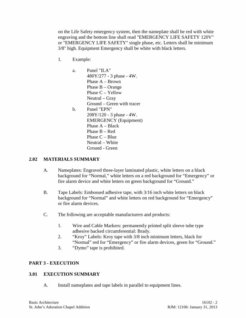
Basis Architecture 16102 - 2 St. John’s Adoration Chapel Addition RJM: 12106: January 31, 2013
on the Life Safety emergency system, then the nameplate shall be red with white engraving and the bottom line shall read "EMERGENCY LIFE SAFETY 120V" or "EMERGENCY LIFE SAFETY" single phase, etc. Letters shall be minimum 3/8" high. Equipment Emergency shall be white with black letters.
1. Example: a. Panel "ILA" 480Y/277 - 3 phase - 4W. Phase A – Brown Phase B – Orange Phase C – Yellow Neutral – Gray Ground – Green with tracer b. Panel "EPN" 208Y/120 - 3 phase - 4W. EMERGENCY (Equipment) Phase A – Black Phase B – Red Phase C – Blue Neutral – White Ground - Green 2.02 MATERIALS SUMMARY
A. Nameplates: Engraved three-layer laminated plastic, white letters on a black background for “Normal,” white letters on a red background for “Emergency” or fire alarm device and white letters on green background for “Ground.”
B. Tape Labels: Embossed adhesive tape, with 3/16 inch white letters on black
background for “Normal” and white letters on red background for “Emergency” or fire alarm devices.
C. The following are acceptable manufacturers and products:
1. Wire and Cable Markers: permanently printed split sleeve tube type
adhesive backed circumferential: Brady. 2. “Kroy” Labels: Kroy tape with 3/8 inch minimum letters, black for
“Normal” red for “Emergency” or fire alarm devices, green for “Ground.” 3. “Dymo” tape is prohibited.
PART 3 - EXECUTION 3.01 EXECUTION SUMMARY A. Install nameplates and tape labels in parallel to equipment lines.
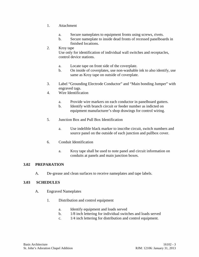
Basis Architecture 16102 - 3 St. John’s Adoration Chapel Addition RJM: 12106: January 31, 2013
1. Attachment
a. Secure nameplates to equipment fronts using screws, rivets. b. Secure nameplate to inside dead fronts of recessed panelboards in
finished locations. 2. Kroy tape Use only for identification of individual wall switches and receptacles,
control device stations.
a. Locate tape on front side of the coverplate. b. On inside of coverplates, use non-washable ink to also identify, use
same as Kroy tape on outside of coverplate.
3. Label “Grounding Electrode Conductor” and “Main bonding Jumper” with engraved tags.
4. Wire Identification
a. Provide wire markers on each conductor in panelboard gutters. b. Identify with branch circuit or feeder number as indicted on
equipment manufacturer’s shop drawings for control wiring.
5. Junction Box and Pull Box Identification
a. Use indelible black marker to inscribe circuit, switch numbers and source panel on the outside of each junction and pullbox cover.
6. Conduit Identification
a. Kroy tape shall be used to note panel and circuit information on
conduits at panels and main junction boxes. 3.02 PREPARATION A. De-grease and clean surfaces to receive nameplates and tape labels. 3.03 SCHEDULES A. Engraved Nameplates
1. Distribution and control equipment
a. Identify equipment and loads served b. 1/8 inch lettering for individual switches and loads served c. 1/4 inch lettering for distribution and control equipment.
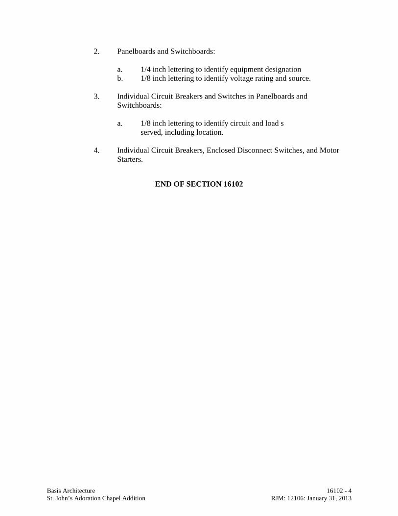
Basis Architecture 16102 - 4 St. John’s Adoration Chapel Addition RJM: 12106: January 31, 2013
2. Panelboards and Switchboards: a. 1/4 inch lettering to identify equipment designation b. 1/8 inch lettering to identify voltage rating and source.
3. Individual Circuit Breakers and Switches in Panelboards and
Switchboards:
a. 1/8 inch lettering to identify circuit and load s served, including location.
4. Individual Circuit Breakers, Enclosed Disconnect Switches, and Motor
Starters.
END OF SECTION 16102
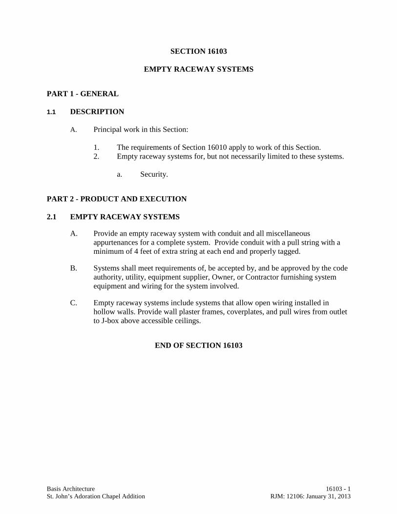
Basis Architecture 16103 - 1 St. John’s Adoration Chapel Addition RJM: 12106: January 31, 2013
SECTION 16103
EMPTY RACEWAY SYSTEMS
PART 1 - GENERAL 1.1 DESCRIPTION
A. Principal work in this Section:
1. The requirements of Section 16010 apply to work of this Section. 2. Empty raceway systems for, but not necessarily limited to these systems.
a. Security.
PART 2 - PRODUCT AND EXECUTION 2.1 EMPTY RACEWAY SYSTEMS
A. Provide an empty raceway system with conduit and all miscellaneous appurtenances for a complete system. Provide conduit with a pull string with a minimum of 4 feet of extra string at each end and properly tagged.
B. Systems shall meet requirements of, be accepted by, and be approved by the code authority, utility, equipment supplier, Owner, or Contractor furnishing system equipment and wiring for the system involved.
C. Empty raceway systems include systems that allow open wiring installed in hollow walls. Provide wall plaster frames, coverplates, and pull wires from outlet to J-box above accessible ceilings.
END OF SECTION 16103
Basis Architecture 16400 - 1 St. John’s Adoration Chapel Addition RJM: 12106: January 31, 2013
SECTION 16400
ELECTRICAL SYSTEMS
PART 1 - GENERAL 1.1 Furnish and install a complete electrical system as shown on Drawings and
Specifications.
PART 2 - PRODUCTS 2.1 MECHANICAL EQUIPMENT
A. Phase protection: All motors 1 HP and above using 3 phase power and all 3 phase air condition units shall have protection for phase reversal, loss of phase or phase unbalance of 10% voltage drop or greater on any one phase. Time Mark (model 2644) or Square D.
B. Electrical contractor shall verify with mechanical contractor prior to rough-in and at shop drawing stage that proper voltages, phases, and connections are provided for all mechanical equipment being furnished on this project. Contractor shall stop work on any incorrect wiring and notify engineer at once.
2.2 VOICE/DATA SYSTEM
A. Provide a complete system of outlets, conduits, equipment space, cabinets, etc., for voice/data company use. System shall be as indicated on Drawings and in accordance with all requirements of Voice/Data Company.
B. All outlets shall be provided with coverplates, per coverplate Specifications. 2.3 EXIT AND EMERGENCY LIGHTING SYSTEM
A. Provide a complete exit and emergency lighting system as indicated on Drawings. Locate all exit lights for maximum visibility. Entire system shall comply with Article 700 of NEC.
B. Provide battery powered emergency standby lighting system as indicated.
PART 3 - EXECUTION 3.1 GROUNDING SYSTEM
A. Ground the entire electrical distribution system, including all raceways, outlets, fixtures, equipment, etc., in full accord with NEC.
Basis Architecture 16400 - 2 St. John’s Adoration Chapel Addition RJM: 12106: January 31, 2013
B. Provide separate grounding conductor in all raceways.
C. Provide separate grounding jumper from the grounding screw of all receptacle devices to the metallic box in which mounted. Jumper may attach to box with a separate grounding screw or clip device. Jumpers may be eliminated if approved self-grounding devices are used.
D. Provide separate bonding conductor, bare copper, for runs of flexible conduit where required by NEC.
E. Provide separate grounding conductor in all runs to exterior lighting standards, such as post lights, signs, etc.
F. All conductors used for grounding and bonding purposes shall be copper, insulated green, only.
G. All ground busses used in distribution equipment and panels shall be copper. 3.2 MECHANICAL EQUIPMENT WIRING SYSTEM
A. Heating, ventilating and air conditioning equipment: Provide branch circuits, feeders, J-boxes, disconnect switches and make all connections to motors and controls for heating, ventilating and air conditioning equipment in accordance with DIVISION 15000 MECHANICAL SCHEDULE.
B. Contractor shall refer to Mechanical Specifications and Plans for all power and control wiring.
C. Provide dedicated 120 volt 20 amp circuit to all control panels. Location and quantities not indicated on drawings. Verify quantities and locations with temperature control contractor and mechanical contractor to verify all locations and provide required circuits.
3.3 EMERGENCY EQUIPMENT
A. Paint red using enamel spray paint for the following: J-boxes, coverplates, panelboards, loadcenters, safety switches, and transformers.
END OF SECTION 16400
Basis Architecture 16410 - 1 St. John’s Adoration Chapel Addition RJM: 12106: January 31, 2013
SECTION 16410
SITE LIGHTING
PART 1 - GENERAL 1.1 GENERAL
A. Furnish and install complete system. B. Related work specified elsewhere:
1. Concrete bases specified in Division 03. 2. General requirements specified in Section 16010.
C. Coordinate location of anchor bolts and conduit in concrete.
PART 2 - PRODUCTS 2.1 PARKING AREA FIXTURES AND POLES
A. As indicated on fixture schedule.
2.2 CONDUIT
A. Type PVC. Section 16110.
2.3 PARKING AREA LIGHT CONTROL
A. Time Switch
1. Standard Electronic 7 day time format switch, 365 day advance holiday
scheduling astronomic option with day 99 set points and automatic daylight saving adjustments, 120 volts.
2. Approved Manufacturers: Tork DWZ100A, or Engineer approved equal. B. Photo Cell
1. 120V. 2. Approved Manufacturers: Paragon CW201-70 Series, Tork, or Engineer
approved equal.
Basis Architecture 16410 - 2 St. John’s Adoration Chapel Addition RJM: 12106: January 31, 2013
C. Lighting Contactor 1. 120V, 30 amps, multi-pole (as shown on Drawings) NEMA 1 enclosure.
Square "D" Class 8903.
PART 3 - EXECUTION 3.1 INSTALLATION
A. Bury conduit 30 inches minimum below finish grade. B. Lighting control shall be photo cell "on" time clock "off" unless noted otherwise
on Drawings.
END OF SECTION 16410
Basis Architecture 16900 - 1 St. John’s Adoration Chapel Addition RJM: 12106: January 31, 2013
SECTION 16900
ELECTRICAL COMPLETION
PART 1 - GENERAL 1.1 GENERAL
A. The entire electrical system shall be left in first-class workable operating
condition and all work shall be complete.
PART 2 - PRODUCTS 2.1 DIRECTORY CARDS
A. Provide labels and neatly typed directory cards for all panelboards and
loadcenters. Directory cards shall indicate the general area and type of electrical load served by each circuit.
PART 3 - EXECUTION 3.1 CLEAN UP
A. Remove all materials, scrap, etc., relative to the electrical installation and leave
the premises in a clean, orderly condition. Any costs to Owner for clean-up of the site will be charged against Contractor.
B. Clean all electrical equipment and materials of all foreign matter. Clean all light
fixtures using only methods and materials as recommended by Manufacturer. 3.2 ACCEPTANCE DEMONSTRATION
A. Upon completion of the work, at a time to be designated by Architect, Contractor
shall demonstrate to Owner the operation of the entire electrical installation, including any and all special systems provided under this contract. Provide instruction manuals and turn over to owner for all equipment listed below: 1. Emergency (Battery Units). 2. Time Clocks
3.3 TEMPORARY WIRING
A. Remove all temporary wiring, outlets, etc., complete.
Basis Architecture 16900 - 2 St. John’s Adoration Chapel Addition RJM: 12106: January 31, 2013
3.4 DRAWINGS A. Deliver "Record" Drawings to Owner.
END OF SECTION 16900