Embed Size (px)
Citation preview
table of contentsintroduction 1about this manual 2features of your PowerPlate™ 2warning and tips 3mounting locations 3system planning 4system configurations 4-10installation 11controls and connections 11-12signal sources 13-14internal signal routing 14-15multi-cross™ crossover and configurations 16-17AC502 operation 18tuning 18-19P450.2 block diagram 20P650.2 block diagram 21P850.2 block diagram 22troubleshooting 23-24specifications 25warranty information 26
introductionAlthough it may be hard to remember, back in the 1970’s, car audio as we now know it didn’t really exist.Sure, music lovers could buy a cassette or 8-track tape deck and some 6" x 9" three-way speakers.Advanced stereo buffs might even add a "power-booster" to increase output too as much as 12 wattsRMS! But none of this really delivered the power to cut through road noise with sound quality thatcompared with the best home audio. Not until 1979 that is, when a/d/s/ introduced the revolutionaryPowerPlate™ P100 amplifier and 300i 2-way plate loudspeakers. Aesthetically, the P100 introduced thelow profile design which has been an a/d/s/ trademark to this day. Technologically, the P100 combined ahigh efficiency switching power supply with a state-of-the-art, discrete high-current stereo poweramplifier. For the first time, a car audio system existed with the musical integrity and dynamic range thatmade you want to take long drives to nowhere, just to listen to the music. High quality car audio wasborn, and the original a/d/s/ PowerPlate™ P100 made it happen.
The latest improvements to the PowerPlate™ line-up include increased heatsink area to facilitate higherpower output, and fully balanced high-level inputs compatible with any source. The amplifier you havepurchased is an enhancement of the respected P-series multichannel amplifiers. In this version, we haveimproved upon the already acclaimed sound quality by addressing internal details, and upgrading selectedcomponents to incorporate the latest technology which was not available when the P-series was originallydesigned. Selected low-noise, high-speed op amps are used in critical circuits. Class-A biasing is usedthroughout the voltage-gain and active crossover stages. Numerous modifications and "tweaks" werealso performed which improve the power supply dynamics and reduce noise. These changes improvetransparency and dynamic linearity, resulting in a smoother and more detailed top-end, tighter bass, moreexplosive dynamic contrasts, and virtually holographic imaging. Left intact are the P-series unequalledflexibility, high efficiency and superb reliability. These, along with multichannel design, are fundamental inthe a/d/s/ approach to systems engineering, which makes achieving true high fidelity reproduction simpleand predictable in any installation.
1
about this manualTo get the most from your a/d/s/ PowerPlate™, we recommend that you have the installation performedby your qualified authorized a/d/s/ dealer. If this unit is installed by your dealer, we will extend the warrantyto two years instead of the standard one-year. However, if you feel that you have the necessary skills andprefer to perform the installation yourself, this manual will guide you through the process of installationand set-up. Please read through it completely before beginning the installation so that you may familiarizeyourself with the total procedure before you begin. If there is anything that you do not fully understand,please consult with your a/d/s/ dealer before attempting the installation.
keep listening, but be safe!Sustained listening to loud music over 100dB has been shown to cause permanent hearing damage.Systems using a/d/s/ components are capable of achieving volume levels, which substantially exceed thislevel. When operating your system for sustained periods at high volume, be sure to use hearing protectionto prevent long-term exposure. We want you to be able to enjoy the music for many more years.
features of your PowerPlate™Transient Perfect™ MOSFET Power Supply - The heart of the P-series, this supply frees thePowerPlate™ from the constraints of common pwm (pulse width modulated) supplies. The advantagesare: extremely fast overload recovery time, low output impedance for superior damping, and stabilityduring voltage fluctuations for reliable performance in the harsh automotive environment.
Detachable Plug in Connectors - High current speaker and power connectors simplifies installation.
Remote Subwoofer Control Capability - Can be used with accessory control AC502 to provide adashboard mounted subwoofer or rear channel level control.
Multi-cross™ Variable Built-in Crossovers - High-pass, Low-pass and Bandpass functions are built-in,virtually eliminating the need for external crossover networks in even the most elaborate systems.
PowerPlate™ Design - a/d/s/ original low profile, high efficiency heatsink design keeps size minimumand allows mounting where space is limited.
Wide Input Sensitivity Range - Allows connection to virtually any source unit from factory OEM radiosthrough low output preamps.
Simultaneous Stereo and Mono - Each channel pair may be used Stereo, Mono, Bridged or both Stereoand Mono simultaneously. This allows an additional Mono speaker to be used with a stereo pair forcenter-channel or subwoofer applications from each channel pair.
Same Side Adjustments - The P-series PowerPlate™ makes system adjustment easy by organizing allsignal-processing controls on one side of the amplifier. This layout allows convenient system adjustmentand facilitates a variety of installation possibilities when access to the controls is desired.
2
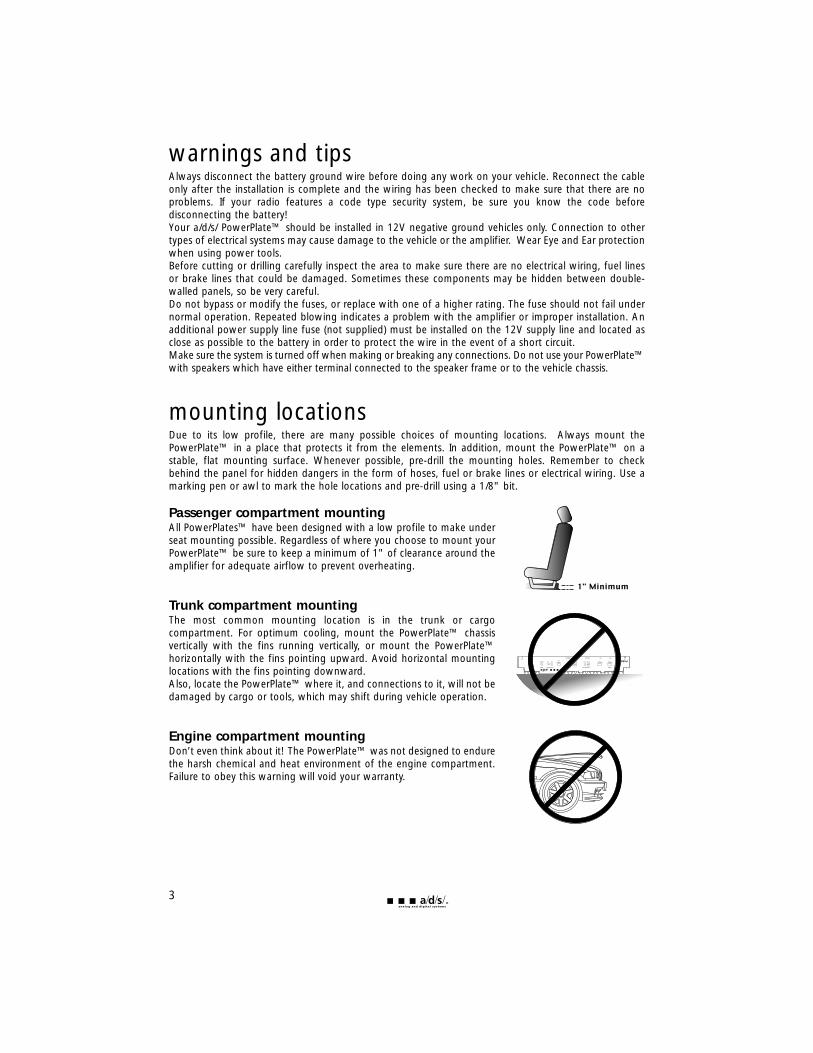
warnings and tipsAlways disconnect the battery ground wire before doing any work on your vehicle. Reconnect the cableonly after the installation is complete and the wiring has been checked to make sure that there are noproblems. If your radio features a code type security system, be sure you know the code beforedisconnecting the battery!Your a/d/s/ PowerPlate™ should be installed in 12V negative ground vehicles only. Connection to othertypes of electrical systems may cause damage to the vehicle or the amplifier. Wear Eye and Ear protectionwhen using power tools.Before cutting or drilling carefully inspect the area to make sure there are no electrical wiring, fuel linesor brake lines that could be damaged. Sometimes these components may be hidden between double-walled panels, so be very careful.Do not bypass or modify the fuses, or replace with one of a higher rating. The fuse should not fail undernormal operation. Repeated blowing indicates a problem with the amplifier or improper installation. Anadditional power supply line fuse (not supplied) must be installed on the 12V supply line and located asclose as possible to the battery in order to protect the wire in the event of a short circuit.Make sure the system is turned off when making or breaking any connections. Do not use your PowerPlate™with speakers which have either terminal connected to the speaker frame or to the vehicle chassis.
mounting locationsDue to its low profile, there are many possible choices of mounting locations. Always mount thePowerPlate™ in a place that protects it from the elements. In addition, mount the PowerPlate™ on astable, flat mounting surface. Whenever possible, pre-drill the mounting holes. Remember to checkbehind the panel for hidden dangers in the form of hoses, fuel or brake lines or electrical wiring. Use amarking pen or awl to mark the hole locations and pre-drill using a 1/8" bit.
Passenger compartment mounting All PowerPlates™ have been designed with a low profile to make underseat mounting possible. Regardless of where you choose to mount yourPowerPlate™ be sure to keep a minimum of 1" of clearance around theamplifier for adequate airflow to prevent overheating.
Trunk compartment mounting The most common mounting location is in the trunk or cargocompartment. For optimum cooling, mount the PowerPlate™ chassisvertically with the fins running vertically, or mount the PowerPlate™horizontally with the fins pointing upward. Avoid horizontal mountinglocations with the fins pointing downward.Also, locate the PowerPlate™ where it, and connections to it, will not bedamaged by cargo or tools, which may shift during vehicle operation.
Engine compartment mounting Don’t even think about it! The PowerPlate™ was not designed to endurethe harsh chemical and heat environment of the engine compartment.Failure to obey this warning will void your warranty.
3
system planningProper system planning is the best way to maximize your PowerPlate’s™ performance. By planning yourinstallation carefully you can avoid situations where the performance or the reliability of your system iscompromised. Your authorized a/d/s/ dealer has been trained to maximize your system’s sonic potential.Your a/d/s/ dealer is a valuable resource in helping you with your system design and installation.
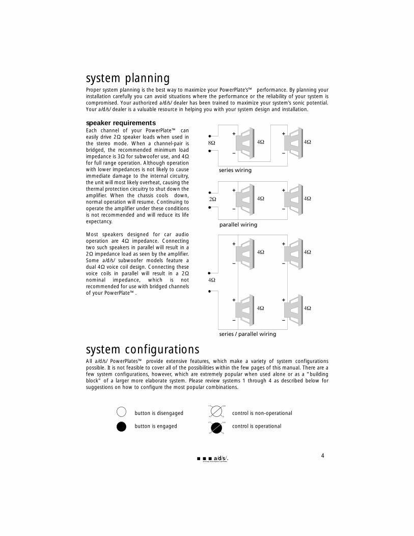
speaker requirementsEach channel of your PowerPlate™ caneasily drive 2Ω speaker loads when used inthe stereo mode. When a channel-pair isbridged, the recommended minimum loadimpedance is 3Ω for subwoofer use, and 4Ωfor full range operation. Although operationwith lower impedances is not likely to causeimmediate damage to the internal circuitry,the unit will most likely overheat, causing thethermal protection circuitry to shut down theamplifier. When the chassis cools down,normal operation will resume. Continuing tooperate the amplifier under these conditionsis not recommended and will reduce its lifeexpectancy.
Most speakers designed for car audiooperation are 4Ω impedance. Connectingtwo such speakers in parallel will result in a2Ω impedance load as seen by the amplifier.Some a/d/s/ subwoofer models feature adual 4Ω voice coil design. Connecting thesevoice coils in parallel will result in a 2Ωnominal impedance, which is notrecommended for use with bridged channelsof your PowerPlate™.
system configurationsAll a/d/s/ PowerPlates™ provide extensive features, which make a variety of system configurationspossible. It is not feasible to cover all of the possibilities within the few pages of this manual. There are afew system configurations, however, which are extremely popular when used alone or as a "buildingblock" of a larger more elaborate system. Please review systems 1 through 4 as described below forsuggestions on how to configure the most popular combinations.
button is disengaged control is non-operational
button is engaged control is operational
4
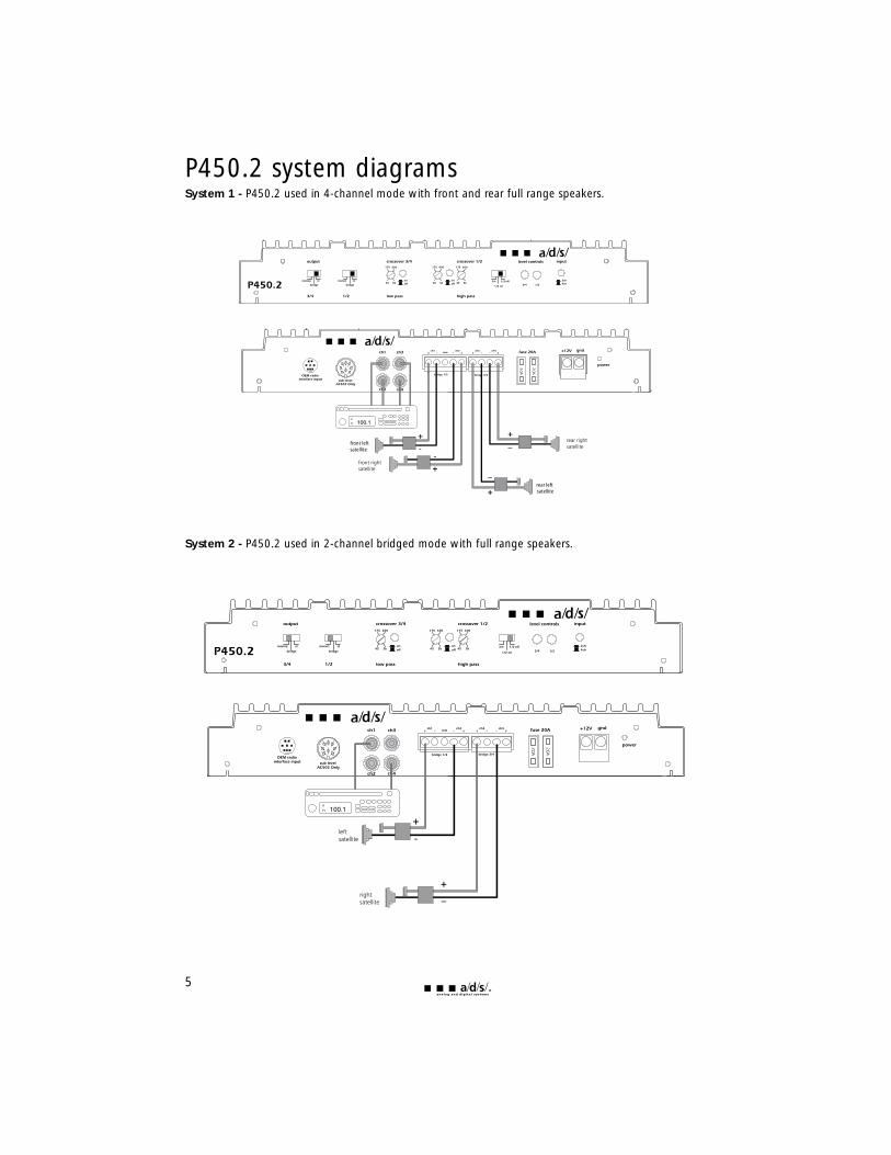
P450.2 system diagramsSystem 1 - P450.2 used in 4-channel mode with front and rear full range speakers.
System 2 - P450.2 used in 2-channel bridged mode with full range speakers.
5
rear left satellite
front leftsatellite
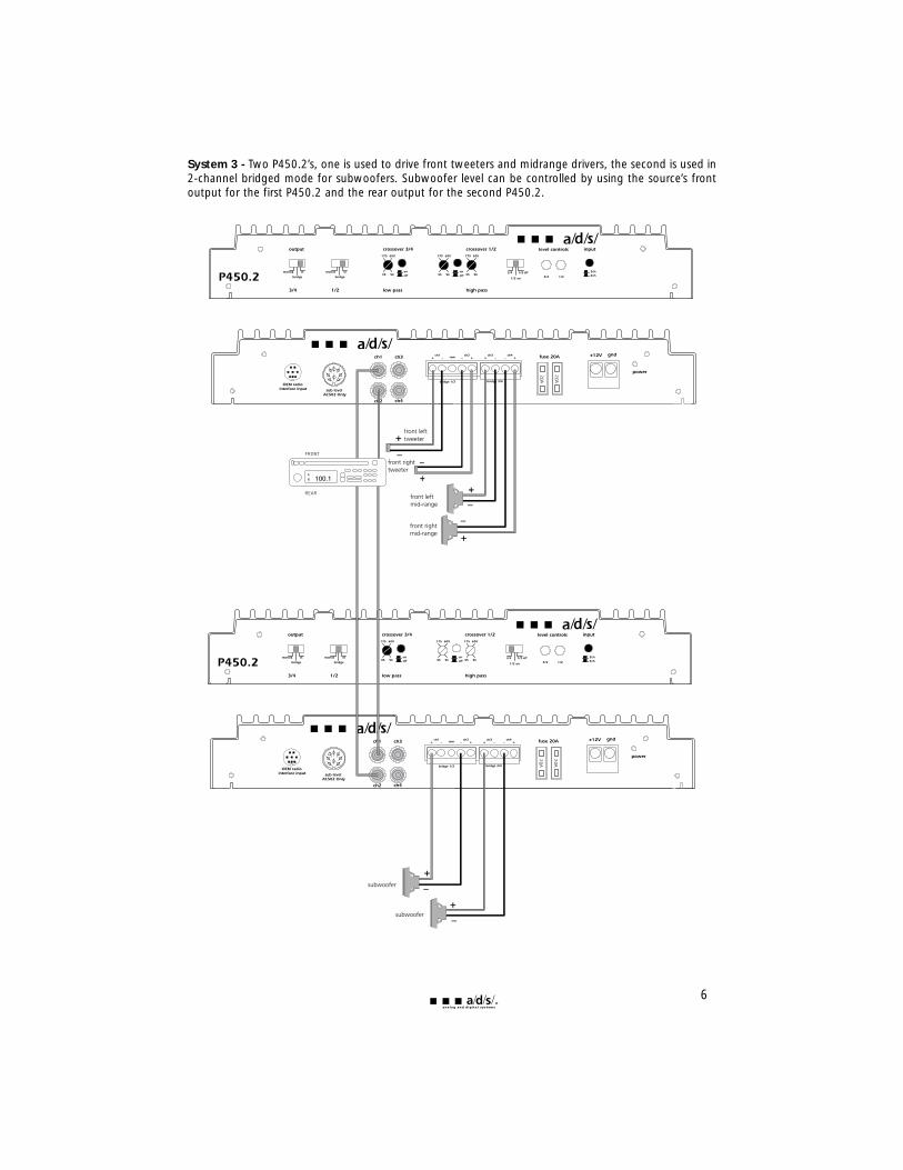
System 3 - Two P450.2’s, one is used to drive front tweeters and midrange drivers, the second is used in2-channel bridged mode for subwoofers. Subwoofer level can be controlled by using the source’s frontoutput for the first P450.2 and the rear output for the second P450.2.
6
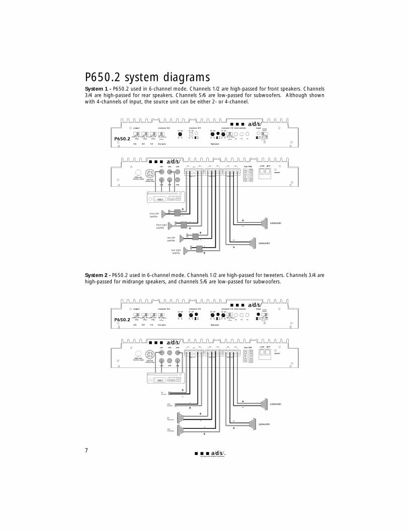
P650.2 system diagramsSystem 1 - P650.2 used in 6-channel mode. Channels 1/2 are high-passed for front speakers. Channels3/4 are high-passed for rear speakers. Channels 5/6 are low-passed for subwoofers. Although shownwith 4-channels of input, the source unit can be either 2- or 4-channel.
System 2 - P650.2 used in 6-channel mode. Channels 1/2 are high-passed for tweeters. Channels 3/4 arehigh-passed for midrange speakers, and channels 5/6 are low-passed for subwoofers.
7
lefttweeter
righttweeter
leftmidrange
rightmidrange
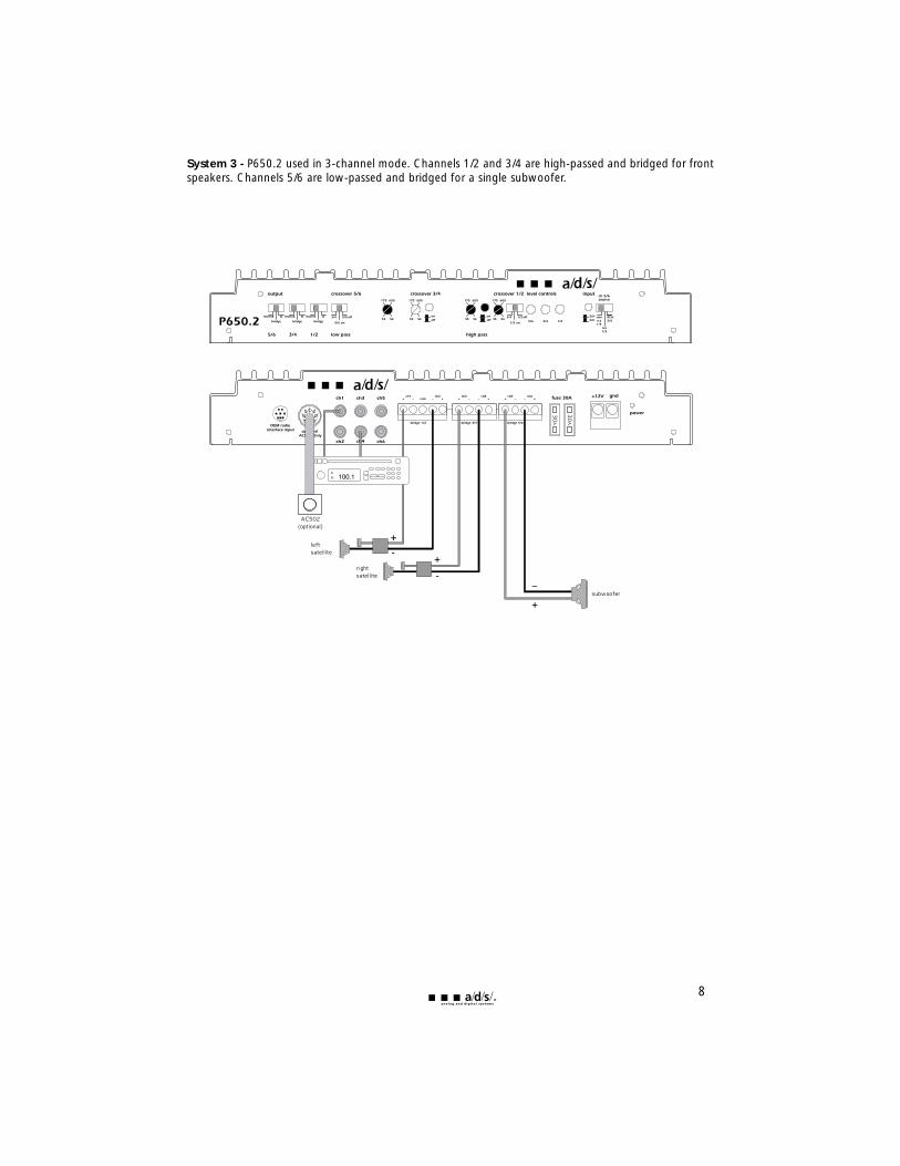
System 3 - P650.2 used in 3-channel mode. Channels 1/2 and 3/4 are high-passed and bridged for frontspeakers. Channels 5/6 are low-passed and bridged for a single subwoofer.
8
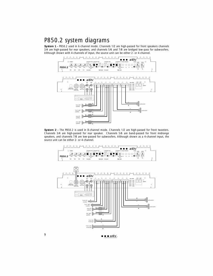
P850.2 system diagramsSystem 1 - P850.2 used in 6-channel mode. Channels 1/2 are high-passed for front speakers channels3/4 are high-passed for rear speakers, and channels 5/6 and 7/8 are bridged low-pass for subwoofers.Although shown with 4-channels of input, the source unit can be either 2- or 4-channel.
System 2 - The P850.2 is used in 8-channel mode. Channels 1/2 are high-passed for front tweeters.Channels 3/4 are high-passed for rear speaker. Channels 5/6 are band-passed for front midrangespeakers, and channels 7/8 are low-passed for subwoofers. Although shown as a 4-channel input, thesource unit can be either 2- or 4-channel.
9
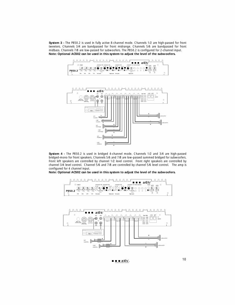
System 3 - The P850.2 is used in fully active 8-channel mode. Channels 1/2 are high-passed for fronttweeters. Channels 3/4 are bandpassed for front midrange. Channels 5/6 are bandpassed for frontmidbass. Channels 7/8 are low-passed for subwoofers. The P850.2 is configured for 2-channel input.Note: Optional AC502 can be used in this system to adjust the level of the subwoofers.
System 4 - The P850.2 is used in bridged 4-channel mode. Channels 1/2 and 3/4 are high-passedbridged-mono for front speakers. Channels 5/6 and 7/8 are low-passed summed bridged for subwoofers.Front left speakers are controlled by channel 1/2 level control. Front right speakers are controlled bychannel 3/4 level control. Channel 5/6 and 7/8 are controlled by channel 5/6 level control. The amp isconfigured for 4 channel input.Note: Optional AC502 can be used in this system to adjust the level of the subwoofers.
10
installation1. Disconnect the battery ground cable. Reconnect the ground cable only after the installation is
complete and the wiring has been checked to make sure that there are no problems. If your radio features a code type security system, be sure you know the code before disconnecting the battery!
2. Run a minimum AWG #8 power wire directly from the battery to the PowerPlate™ mountinglocation. Install a fuseholder at the battery end of this cable either within 18" of the battery or before the wire runs through any metal partitions. Do not install the fuse at this time.
3. Attach a minimum AWG #8 ground wire to a solid chassis ground point near the mounting location. Keep this wire as short as possible. Scrape all paint and primer off of the sheet metal at the ground point to ensure a good electrical connection. Attach the wire to the ground point with a nut, bolt and star washer.
4. Run the signal leads and remote turn-on leads from the head unit to the PowerPlate™ location. If using an internally powered radio or factory radio refer to the "signal sources" section for the proper wiring connections.
5. Install the speakers and run each of the speaker leads to the PowerPlate™ location. Connect the speaker, remote, and power wires to the appropriate terminals on the plug-in terminal blocks. Refer to the "controls and connections" or "system planning" sections for information on the proper connections. The speaker terminal blocks install with the set screws facing up and power terminal block installs with the set screws facing down.
6. Preset the 2/4 channel selector switch, crossover and channel mode switches, and crossover frequency switches to the desired positions. Refer to the "controls and connections" section for more information.
7. Adjust all amplifier input level controls to the 1/4 position.
8. Mount the amplifier into position and plug in the power and speaker terminals. Attach the input signal cables.
9. Reattach the battery ground cable.
10. Double check your switch and control settings. Install a proper sized fuse in the fuseholder youhave installed near the battery.
11. Turn on the signal source at a low volume level. Using the balance and fader controls, check tosee that each channel is connected to the proper speakers. Make sure that the proper frequency range is being sent to each speaker if you are using the crossover features built into your PowerPlate™.
12. Adjust the input sensitivity and crossover frequencies as described in the "tuning" section.
13. Read the rest of this manual to get maximum enjoyment from your system.
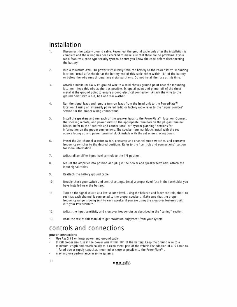
controls and connectionspower connections• Use AWG #8 or larger power and ground cable.• Install proper size fuse in the power wire within 18" of the battery. Keep the ground wire to a
minimum length and attach solidly to a clean metal part of the vehicle.The addition of a .5 Farad to1 Farad power supply capacitor, mounted as close as possible to the PowerPlate™,
• may improve performance in some systems.
11
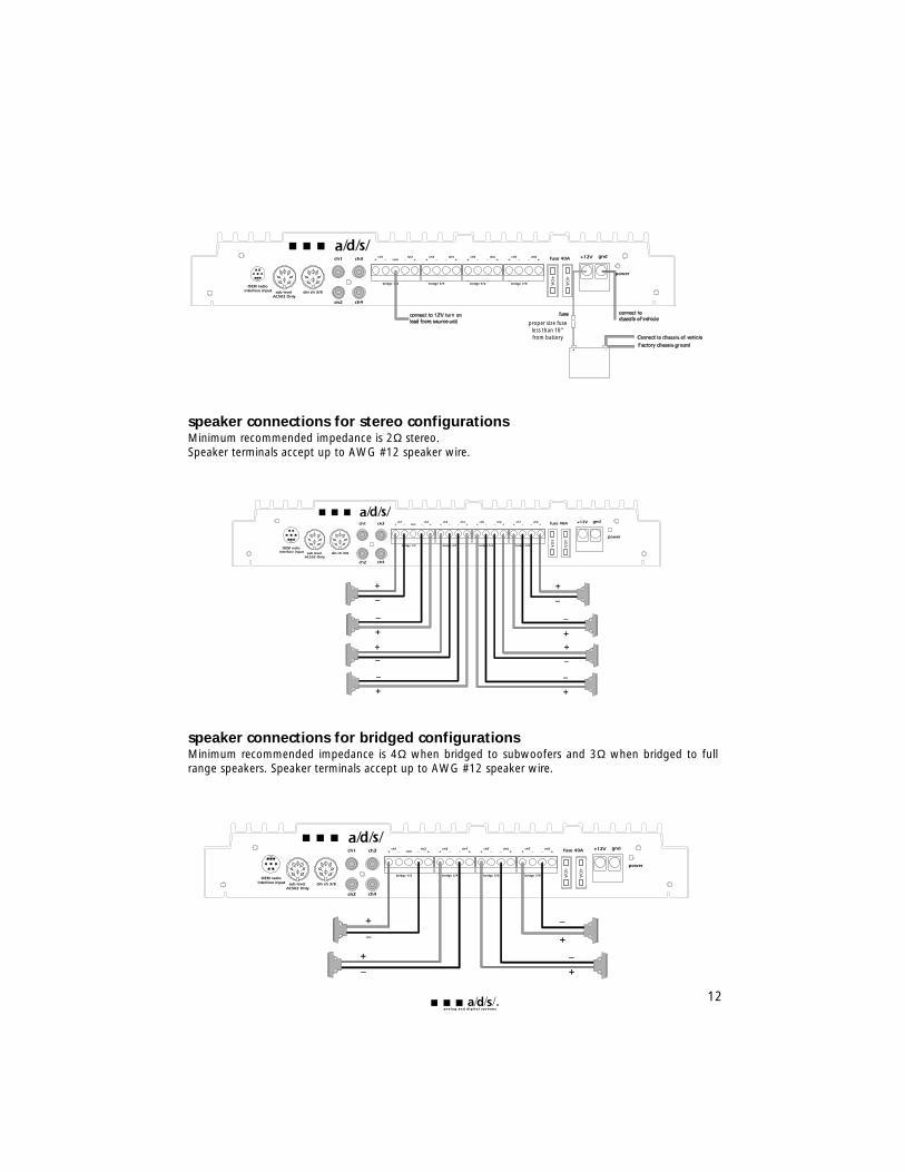
speaker connections for stereo configurations Minimum recommended impedance is 2Ω stereo.Speaker terminals accept up to AWG #12 speaker wire.
speaker connections for bridged configurations Minimum recommended impedance is 4Ω when bridged to subwoofers and 3Ω when bridged to fullrange speakers. Speaker terminals accept up to AWG #12 speaker wire.
12
proper size fuseless than 18" from battery
signal sourcesDue to the wide input level adjustment range, all a/d/s/ PowerPlates™ can be driven with either aconventional preamplifier drive signal or the amplifier signal from a powered source unit. This makes thePowerPlate™ perfect for upgrading an OEM (Original Equipment Manufacturer) stereo system whileretaining the factory installed radio.
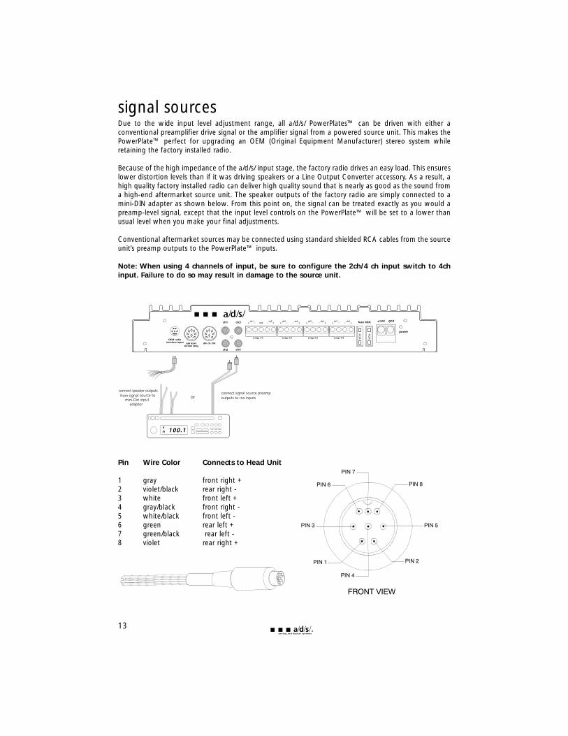
Because of the high impedance of the a/d/s/ input stage, the factory radio drives an easy load. This ensureslower distortion levels than if it was driving speakers or a Line Output Converter accessory. As a result, ahigh quality factory installed radio can deliver high quality sound that is nearly as good as the sound froma high-end aftermarket source unit. The speaker outputs of the factory radio are simply connected to amini-DIN adapter as shown below. From this point on, the signal can be treated exactly as you would apreamp-level signal, except that the input level controls on the PowerPlate™ will be set to a lower thanusual level when you make your final adjustments.
Conventional aftermarket sources may be connected using standard shielded RCA cables from the sourceunit’s preamp outputs to the PowerPlate™ inputs.
Note: When using 4 channels of input, be sure to configure the 2ch/4 ch input switch to 4chinput. Failure to do so may result in damage to the source unit.
Pin Wire Color Connects to Head Unit
1 gray front right + 2 violet/black rear right - 3 white front left + 4 gray/black front right - 5 white/black front left - 6 green rear left + 7 green/black rear left - 8 violet rear right +
13
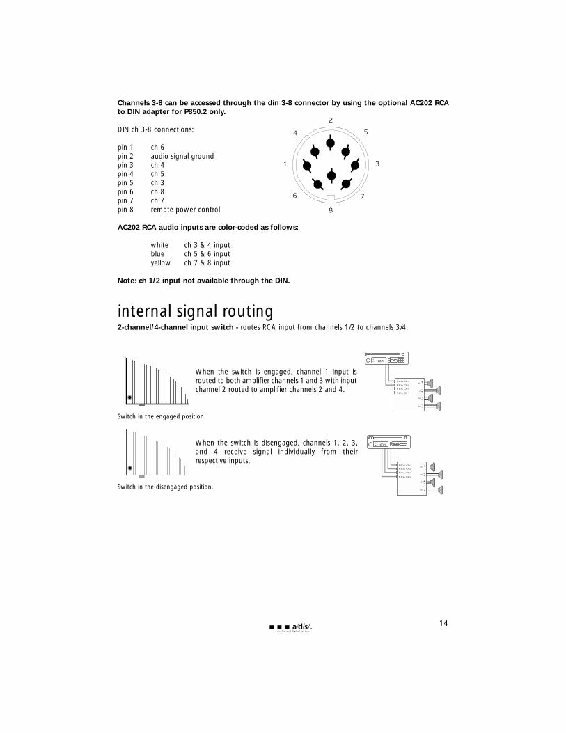
Channels 3-8 can be accessed through the din 3-8 connector by using the optional AC202 RCAto DIN adapter for P850.2 only.
DIN ch 3-8 connections:
pin 1 ch 6pin 2 audio signal groundpin 3 ch 4pin 4 ch 5pin 5 ch 3pin 6 ch 8pin 7 ch 7pin 8 remote power control
AC202 RCA audio inputs are color-coded as follows:
white ch 3 & 4 inputblue ch 5 & 6 inputyellow ch 7 & 8 input
Note: ch 1/2 input not available through the DIN.
internal signal routing2-channel/4-channel input switch - routes RCA input from channels 1/2 to channels 3/4.
When the switch is engaged, channel 1 input isrouted to both amplifier channels 1 and 3 with inputchannel 2 routed to amplifier channels 2 and 4.
Switch in the engaged position.
When the switch is disengaged, channels 1, 2, 3,and 4 receive signal individually from theirrespective inputs.
Switch in the disengaged position.
14
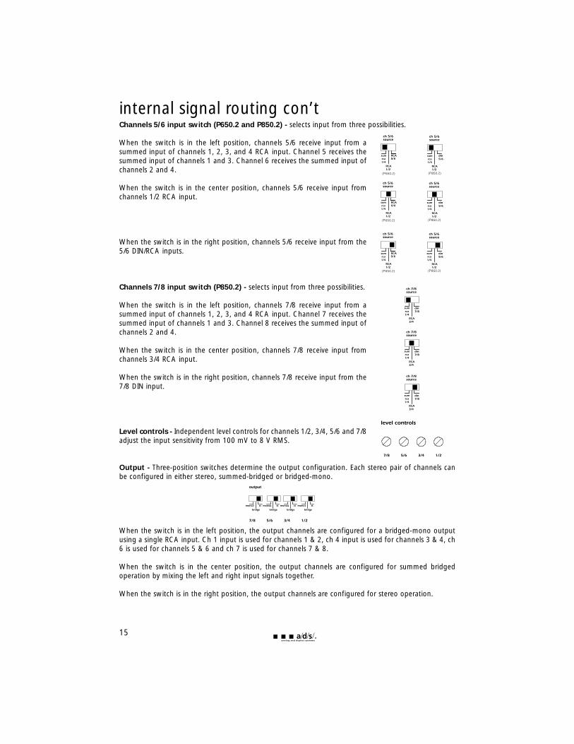
internal signal routing con’tChannels 5/6 input switch (P650.2 and P850.2) - selects input from three possibilities.
When the switch is in the left position, channels 5/6 receive input from asummed input of channels 1, 2, 3, and 4 RCA input. Channel 5 receives thesummed input of channels 1 and 3. Channel 6 receives the summed input ofchannels 2 and 4.
When the switch is in the center position, channels 5/6 receive input fromchannels 1/2 RCA input.
When the switch is in the right position, channels 5/6 receive input from the5/6 DIN/RCA inputs.
Channels 7/8 input switch (P850.2) - selects input from three possibilities.
When the switch is in the left position, channels 7/8 receive input from asummed input of channels 1, 2, 3, and 4 RCA input. Channel 7 receives thesummed input of channels 1 and 3. Channel 8 receives the summed input ofchannels 2 and 4.
When the switch is in the center position, channels 7/8 receive input fromchannels 3/4 RCA input.
When the switch is in the right position, channels 7/8 receive input from the7/8 DIN input.
Level controls - Independent level controls for channels 1/2, 3/4, 5/6 and 7/8adjust the input sensitivity from 100 mV to 8 V RMS.
Output - Three-position switches determine the output configuration. Each stereo pair of channels canbe configured in either stereo, summed-bridged or bridged-mono.
When the switch is in the left position, the output channels are configured for a bridged-mono outputusing a single RCA input. Ch 1 input is used for channels 1 & 2, ch 4 input is used for channels 3 & 4, ch6 is used for channels 5 & 6 and ch 7 is used for channels 7 & 8.
When the switch is in the center position, the output channels are configured for summed bridgedoperation by mixing the left and right input signals together.
When the switch is in the right position, the output channels are configured for stereo operation.
15
5/6
5/6
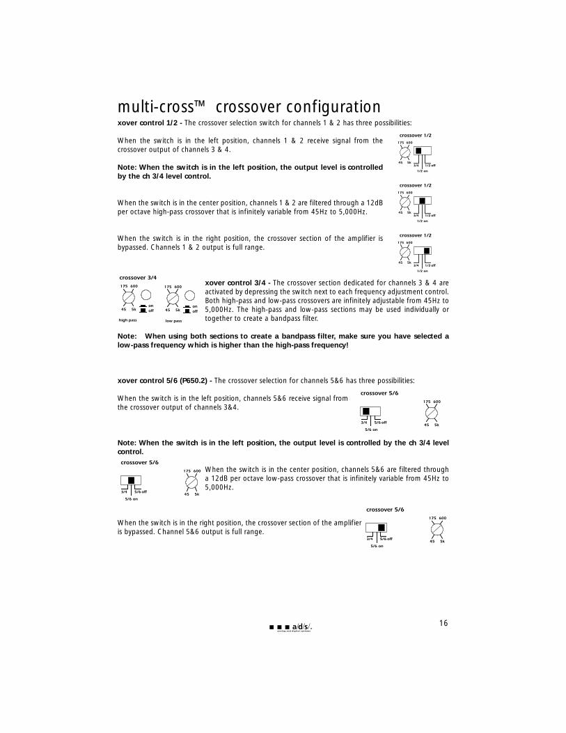
multi-cross™ crossover configurationxover control 1/2 - The crossover selection switch for channels 1 & 2 has three possibilities:
When the switch is in the left position, channels 1 & 2 receive signal from thecrossover output of channels 3 & 4.
Note: When the switch is in the left position, the output level is controlledby the ch 3/4 level control.
When the switch is in the center position, channels 1 & 2 are filtered through a 12dBper octave high-pass crossover that is infinitely variable from 45Hz to 5,000Hz.
When the switch is in the right position, the crossover section of the amplifier isbypassed. Channels 1 & 2 output is full range.
xover control 3/4 - The crossover section dedicated for channels 3 & 4 areactivated by depressing the switch next to each frequency adjustment control.Both high-pass and low-pass crossovers are infinitely adjustable from 45Hz to5,000Hz. The high-pass and low-pass sections may be used individually ortogether to create a bandpass filter.
Note: When using both sections to create a bandpass filter, make sure you have selected alow-pass frequency which is higher than the high-pass frequency!
xover control 5/6 (P650.2) - The crossover selection for channels 5&6 has three possibilities:
When the switch is in the left position, channels 5&6 receive signal fromthe crossover output of channels 3&4.
Note: When the switch is in the left position, the output level is controlled by the ch 3/4 levelcontrol.
When the switch is in the center position, channels 5&6 are filtered througha 12dB per octave low-pass crossover that is infinitely variable from 45Hz to5,000Hz.
When the switch is in the right position, the crossover section of the amplifieris bypassed. Channel 5&6 output is full range.
16
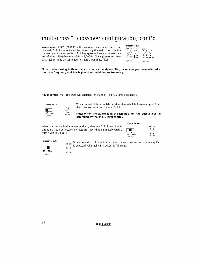
multi-cross™ crossover configuration, cont'dxover control 5/6 (P850.2) - The crossover section dedicated forchannels 5 & 6 are activated by depressing the switch next to thefrequency adjustment control. Both high-pass and low-pass crossoversare infinitely adjustable from 45Hz to 5,000Hz. The high-pass and low-pass sections may be combined to create a bandpass filter.
Note: When using both sections to create a bandpass filter, make sure you have selected alow-pass frequency which is higher than the high-pass frequency!
xover control 7/8 - The crossover selection for channels 7&8 has three possibilities:
When the switch is in the left position, channels 7 & 8 receive signal fromthe crossover output of channels 5 & 6.
Note: When the switch is in the left position, the output level iscontrolled by the ch 5/6 level control.
When the switch is the center position, channels 7 & 8 are filteredthrough a 12dB per octave low-pass crossover that is infinitely variablefrom 45Hz to 5,000Hz.
When the switch is in the right position, the crossover section of the amplifieris bypassed. Channel 7 & 8 output is full range.
17
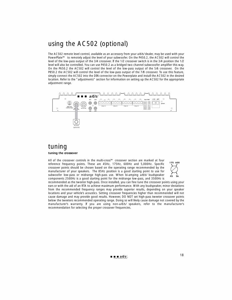
using the AC502 (optional)The AC502 remote level control, available as an accessory from your a/d/s/ dealer, may be used with yourPowerPlate™ to remotely adjust the level of your subwoofer. On the P450.2, the AC502 will control thelevel of the low-pass output of the 3/4 crossover. If the 1/2 crossover switch is in the 3/4 position the 1/2level will also be controlled. You can use P450.2 as a bridged two channel subwooofer amplifier this way.On the P650.2 the AC502 will control the level of the low-pass output of the 5/6 crossover. On theP850.2 the AC502 will control the level of the low-pass output of the 7/8 crossover. To use this feature,simply connect the AC502 into the DIN connector on the Powerplate and install the AC502 in the desiredlocation. Refer to the "adjustments" section for information on setting up the AC502 for the appropriateadjustment range.
tuningtuning the crossover
All of the crossover controls in the multi-cross™ crossover section are marked at fourreference frequency points. These are 45Hz, 175Hz, 600Hz and 5,000Hz. Specificcrossover points should be chosen based on the operating range recommended by themanufacturer of your speakers. The 85Hz position is a good starting point to use forsubwoofer low-pass or midrange high-pass use. When bi-amping a/d/s/ loudspeakercomponents 2500Hz is a good starting point for the midrange low-pass, and 3500Hz isrecommended as the tweeter high-pass. Once installed, you can fine tune the crossover points using yourears or with the aid of an RTA to achieve maximum performance. With any loudspeaker, minor deviationsfrom the recommended frequency ranges may provide superior results, depending on your speakerlocations and your vehicle’s acoustics. Setting crossover frequencies higher than recommended will notcause damage and may provide good results. However, DO NOT set high-pass tweeter crossover pointsbelow the tweeters recommended operating range. Doing so will likely cause damage not covered by themanufacturer’s warranty. If you are using non-a/d/s/ speakers, refer to the manufacturer’srecommendation for selecting the proper crossover frequencies.
18
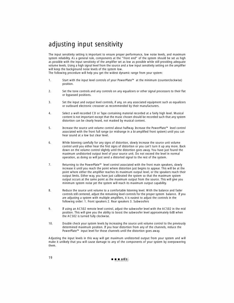
adjusting input sensitivityThe input sensitivity setting is important to ensure proper performance, low noise levels, and maximumsystem reliability. As a general rule, components at the "front end" of the system should be set as highas possible with the input sensitivity of the amplifier set as low as possible while still providing adequatevolume levels. Using a high signal level from the source and a low input sensitivity setting on the amplifierwill keep the background noise levels of the system low. The following procedure will help you get the widest dynamic range from your system:
1. Start with the input level controls of your PowerPlate™ at the minimum (counterclockwise) position.
2. Set the tone controls and any controls on any equalizers or other signal processors to their flator bypassed positions.
3. Set the input and output level controls, if any, on any associated equipment such as equalizersor outboard electronic crossover as recommended by their manufacturers.
4. Select a well recorded CD or Tape containing material recorded at a fairly high level. Musical content is not important except that the music chosen should be recorded such that any systemdistortion can be clearly heard, not masked by musical content.
5. Increase the source unit volume control about halfway. Increase the PowerPlate™ level controlassociated with the front full range (or midrange in a bi-amplified front system) until you can hear sound at a low but clear level.
6. While listening carefully for any signs of distortion, slowly increase the source unit volume control until you either hear the first signs of distortion or you can’t turn it up any more. Backdown on the volume control slightly until the distortion goes away. You have just found the maximum undistorted output level of your source unit. Do not exceed the level in normal operation, as doing so will just send a distorted signal to the rest of the system.
7. Returning to the PowerPlate™ level control associated with the front main speakers, slowly increase it until you reach the point where distortion just begins to appear. This will be at the point where either the amplifier reaches its maximum output level, or the speakers reach theiroutput limits. Either way, you have just calibrated the system so that the maximum system output occurs at the same point as the maximum output from the source. This will give you minimum system noise yet the system will reach its maximum output capability.
8. Reduce the source unit volume to a comfortable listening level. With the balance and fader controls still centered, adjust the remaining level controls for the proper system balance. If youare adjusting a system with multiple amplifiers, it is easiest to adjust the controls in the following order: 1. Front speakers 2. Rear speakers 3. Subwoofers
9. If using an AC502 remote level control, adjust the subwoofer level with the AC502 in the midposition. This will give you the ability to boost the subwoofer level approximately 6dB when the AC502 is turned fully clockwise.
10. Double check your system levels by increasing the source unit volume control to the previouslydetermined maximum position. If you hear distortion from any of the channels, reduce the PowerPlate™ input level for those channels until the distortion goes away.
Adjusting the input levels in this way will get maximum undistorted output from your system and willmake it unlikely that you will cause damage to any of the components of your system by overpoweringthem.
19
20
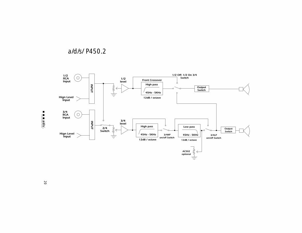
a/d/s/ P450.2
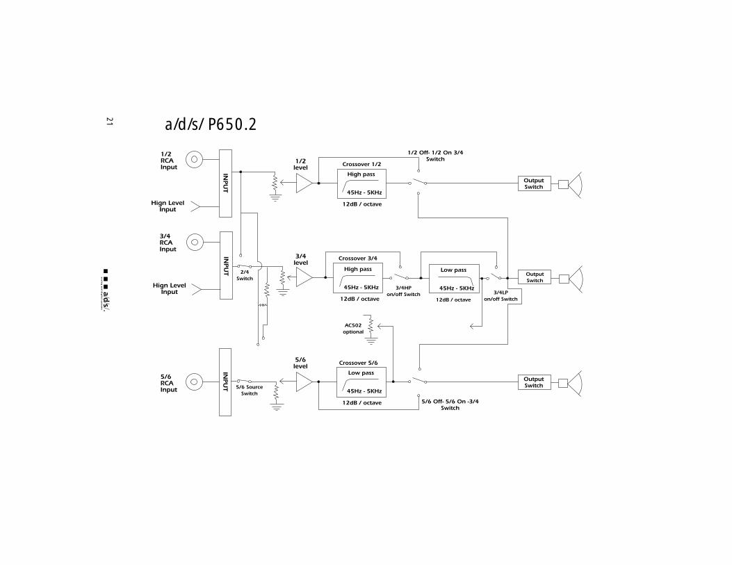
21 a/d/s/ P650.2
22
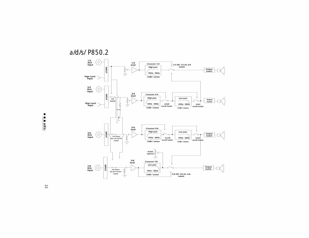
a/d/s/ P850.2

troubleshootingsymptom possible cause action to takeno output low or no remote turn-on check remote turn-on voltage
input output at amplifier and correctas needed
fuse blown check power wire integrity and reversed polarity, repairas needed and replace fuse
power wires not connected check power wire and groundconnections and repair or replace as needed
audio input not connected check input connections and or no output from source signal integrity, repair or
replace as needed
speaker wires not connected check speaker wires and repairor replace as needed
audio cycles on and off speakers are blown check system with knownworking speaker and repair or replace speakers as needed
thermal protection engages make sure there is properwhen amplifier heatsink ventilation for amplifier and temperature exceeds 90° C improve ventilation as needed
loose or poor audio input check input connections andrepair or replace as needed
distorted output amplifier level sensitivity set too reset gain referring to the high; exceeding maximum tuning section of the manual output capability of amplifier for detailed instructions
impedance load to amplifier too check speaker impedance loadlow if below 2Ω stereo or 4Ω
mono rewire speakers to achieve a higher impedance
shorted speaker wires check speaker wire connections and repair or replace as needed
speaker not connected to check speaker wiring and amplifier properly repair or replace as needed
refer to the installation sectionof this manual for detailed instructions
internal crossover not set reset crossovers referring to theproperly for speaker multi-cross™ crossover
configuration section of thismanual
23
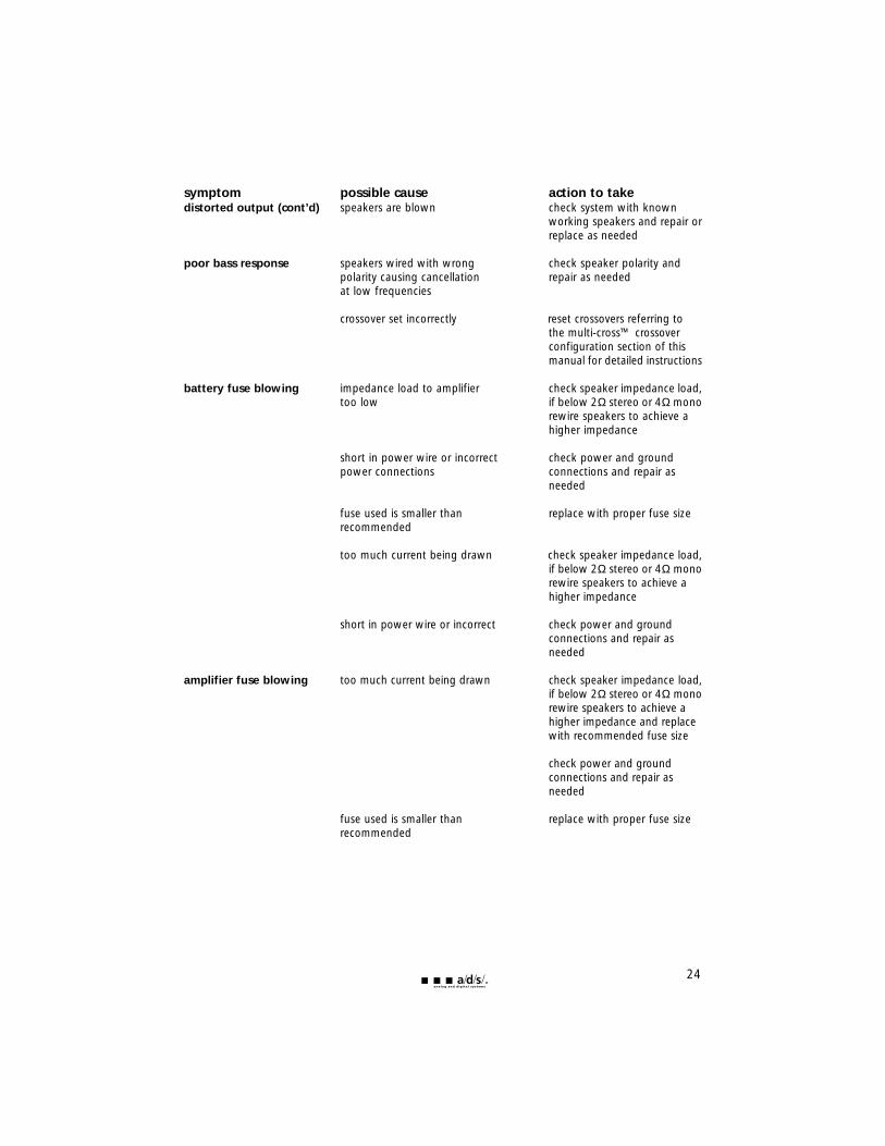
symptom possible cause action to takedistorted output (cont’d) speakers are blown check system with known
working speakers and repair orreplace as needed
poor bass response speakers wired with wrong check speaker polarity and polarity causing cancellation repair as neededat low frequencies
crossover set incorrectly reset crossovers referring tothe multi-cross™ crossover configuration section of this manual for detailed instructions
battery fuse blowing impedance load to amplifier check speaker impedance load,too low if below 2Ω stereo or 4Ω mono
rewire speakers to achieve a higher impedance
short in power wire or incorrect check power and ground power connections connections and repair as
needed
fuse used is smaller than replace with proper fuse sizerecommended
too much current being drawn check speaker impedance load,if below 2Ω stereo or 4Ω mono rewire speakers to achieve ahigher impedance
short in power wire or incorrect check power and ground connections and repair asneeded
amplifier fuse blowing too much current being drawn check speaker impedance load,if below 2Ω stereo or 4Ω monorewire speakers to achieve a higher impedance and replacewith recommended fuse size
check power and ground connections and repair asneeded
fuse used is smaller than replace with proper fuse sizerecommended
24
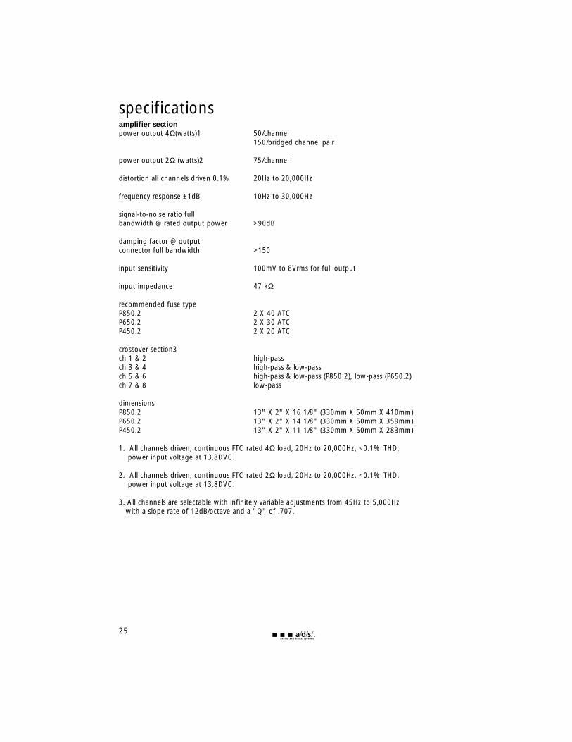
specificationsamplifier sectionpower output 4Ω(watts)1 50/channel
150/bridged channel pair
power output 2Ω (watts)2 75/channel
distortion all channels driven 0.1% 20Hz to 20,000Hz
frequency response ±1dB 10Hz to 30,000Hz
signal-to-noise ratio fullbandwidth @ rated output power >90dB
damping factor @ outputconnector full bandwidth >150
input sensitivity 100mV to 8Vrms for full output
input impedance 47 kΩ
recommended fuse typeP850.2 2 X 40 ATCP650.2 2 X 30 ATCP450.2 2 X 20 ATC
crossover section3ch 1 & 2 high-passch 3 & 4 high-pass & low-passch 5 & 6 high-pass & low-pass (P850.2), low-pass (P650.2)ch 7 & 8 low-pass
dimensionsP850.2 13" X 2" X 16 1/8" (330mm X 50mm X 410mm)P650.2 13" X 2" X 14 1/8" (330mm X 50mm X 359mm)P450.2 13" X 2" X 11 1/8" (330mm X 50mm X 283mm)
1. All channels driven, continuous FTC rated 4Ω load, 20Hz to 20,000Hz, <0.1% THD, power input voltage at 13.8DVC.
2. All channels driven, continuous FTC rated 2Ω load, 20Hz to 20,000Hz, <0.1% THD, power input voltage at 13.8DVC.
3. All channels are selectable with infinitely variable adjustments from 45Hz to 5,000Hz with a slope rate of 12dB/octave and a "Q" of .707.
25
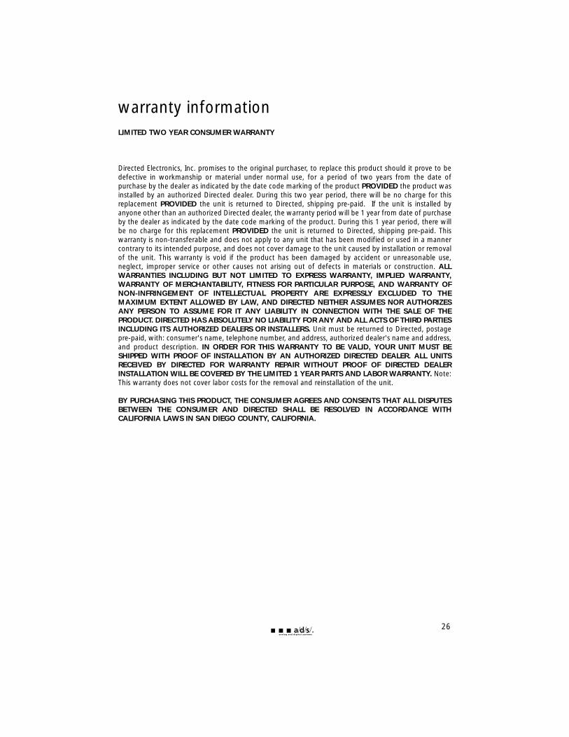
warranty informationLIMITED TWO YEAR CONSUMER WARRANTY
Directed Electronics, Inc. promises to the original purchaser, to replace this product should it prove to bedefective in workmanship or material under normal use, for a period of two years from the date ofpurchase by the dealer as indicated by the date code marking of the product PROVIDED the product wasinstalled by an authorized Directed dealer. During this two year period, there will be no charge for thisreplacement PROVIDED the unit is returned to Directed, shipping pre-paid. If the unit is installed byanyone other than an authorized Directed dealer, the warranty period will be 1 year from date of purchaseby the dealer as indicated by the date code marking of the product. During this 1 year period, there willbe no charge for this replacement PROVIDED the unit is returned to Directed, shipping pre-paid. Thiswarranty is non-transferable and does not apply to any unit that has been modified or used in a mannercontrary to its intended purpose, and does not cover damage to the unit caused by installation or removalof the unit. This warranty is void if the product has been damaged by accident or unreasonable use,neglect, improper service or other causes not arising out of defects in materials or construction. ALLWARRANTIES INCLUDING BUT NOT LIMITED TO EXPRESS WARRANTY, IMPLIED WARRANTY,WARRANTY OF MERCHANTABILITY, FITNESS FOR PARTICULAR PURPOSE, AND WARRANTY OFNON-INFRINGEMENT OF INTELLECTUAL PROPERTY ARE EXPRESSLY EXCLUDED TO THEMAXIMUM EXTENT ALLOWED BY LAW, AND DIRECTED NEITHER ASSUMES NOR AUTHORIZESANY PERSON TO ASSUME FOR IT ANY LIABILITY IN CONNECTION WITH THE SALE OF THEPRODUCT. DIRECTED HAS ABSOLUTELY NO LIABILITY FOR ANY AND ALL ACTS OF THIRD PARTIESINCLUDING ITS AUTHORIZED DEALERS OR INSTALLERS. Unit must be returned to Directed, postagepre-paid, with: consumer's name, telephone number, and address, authorized dealer's name and address,and product description. IN ORDER FOR THIS WARRANTY TO BE VALID, YOUR UNIT MUST BESHIPPED WITH PROOF OF INSTALLATION BY AN AUTHORIZED DIRECTED DEALER. ALL UNITSRECEIVED BY DIRECTED FOR WARRANTY REPAIR WITHOUT PROOF OF DIRECTED DEALERINSTALLATION WILL BE COVERED BY THE LIMITED 1 YEAR PARTS AND LABOR WARRANTY. Note:This warranty does not cover labor costs for the removal and reinstallation of the unit.
BY PURCHASING THIS PRODUCT, THE CONSUMER AGREES AND CONSENTS THAT ALL DISPUTESBETWEEN THE CONSUMER AND DIRECTED SHALL BE RESOLVED IN ACCORDANCE WITHCALIFORNIA LAWS IN SAN DIEGO COUNTY, CALIFORNIA.
26