Embed Size (px)
Citation preview
Adsorption Storage
A viable alternative to compression
for natural gas powered vehicles ?
David Quinn
Royal Military College of Canada
Presented to
ALL-CRAFT Columbia, MoJuly,2005
Natural Gas as a Vehicular Fuel
Excellent fuel, Clean burning, no deposits No additives,
High Octane Number, 130 RON
Worldwide, more than a million vehicles
operate using CNG as their fuel source.
Used as a vehicular fuel for nearly a century!
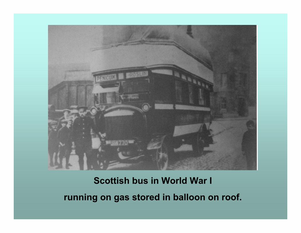
Scottish bus in World War I
running on gas stored in balloon on roof.
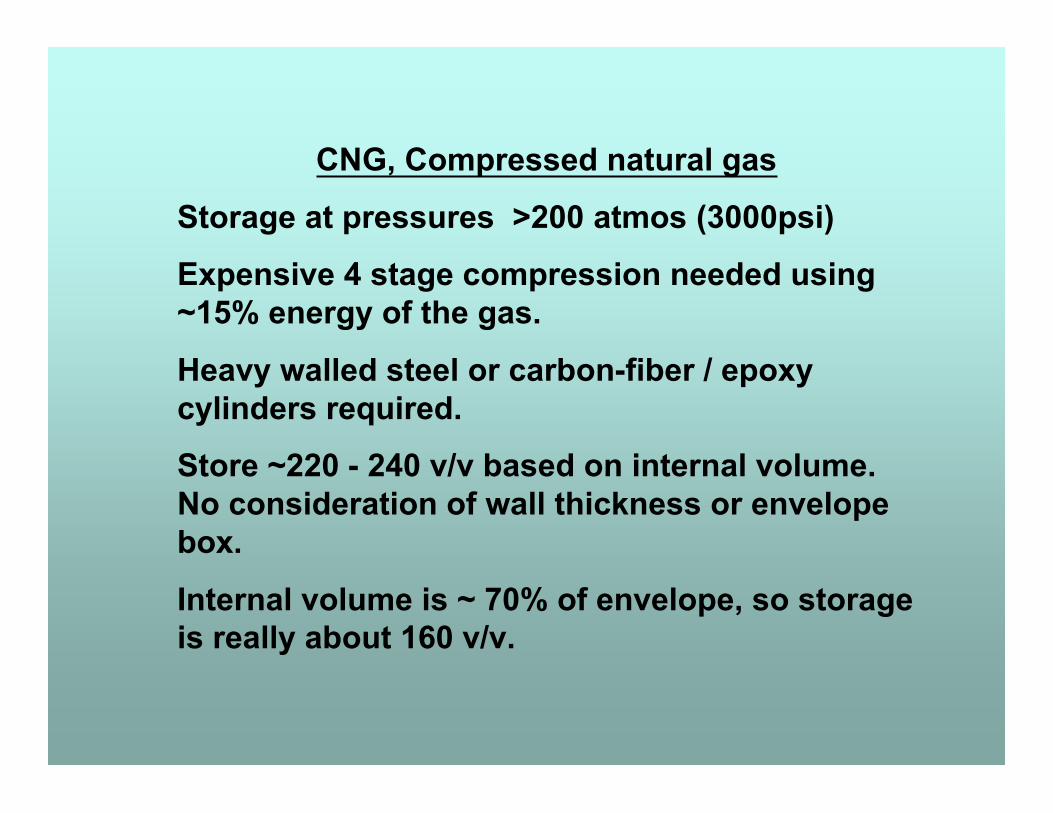
CNG, Compressed natural gas
Storage at pressures >200 atmos (3000psi)
Expensive 4 stage compression needed using~15% energy of the gas.
Heavy walled steel or carbon-fiber / epoxycylinders required.
Store ~220 - 240 v/v based on internal volume.No consideration of wall thickness or envelopebox.
Internal volume is ~ 70% of envelope, so storageis really about 160 v/v.
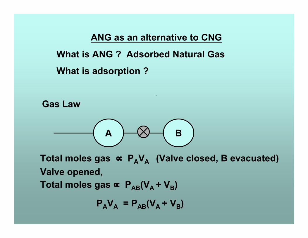
ANG as an alternative to CNG
What is ANG ? Adsorbed Natural Gas
What is adsorption ?
Gas Law
A B
Total moles gas ∝ PAVA (Valve closed, B evacuated)Valve opened,Total moles gas ∝ PAB(VA + VB)
PAVA = PAB(VA + VB)
A B
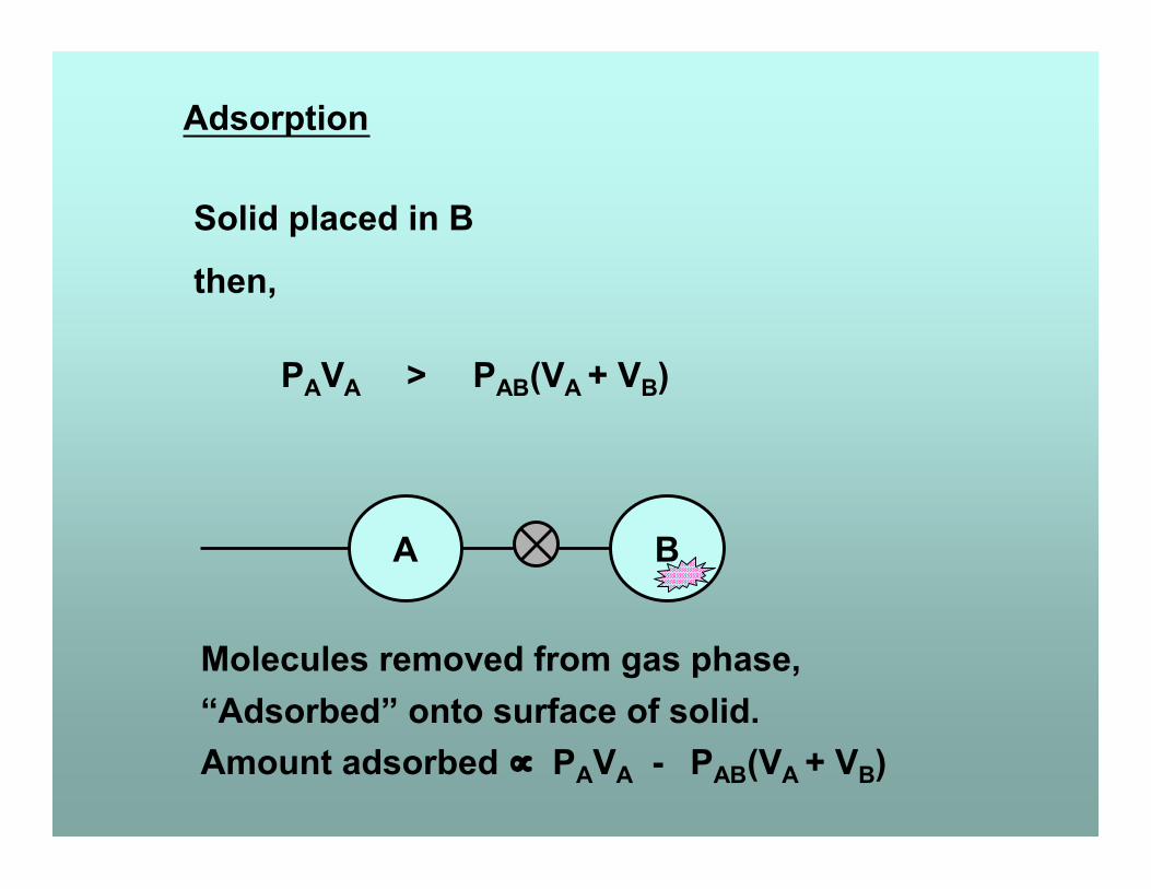
Adsorption
Solid placed in B
then,
PAVA > PAB(VA + VB)
Molecules removed from gas phase,“Adsorbed” onto surface of solid.Amount adsorbed ∝ PAVA - PAB(VA + VB)
Extent of adsorption
dependent on,
1. Temperature
2. Adsorption potential of surface
3. Amount of available surface
1. Temperature
Lower temperature, greater adsorption,Higher temperature, lower adsorption.
Simplify to realistic temperature for vehicular use,constant temperature, (isothermal), of 298Kfor experimental studies.
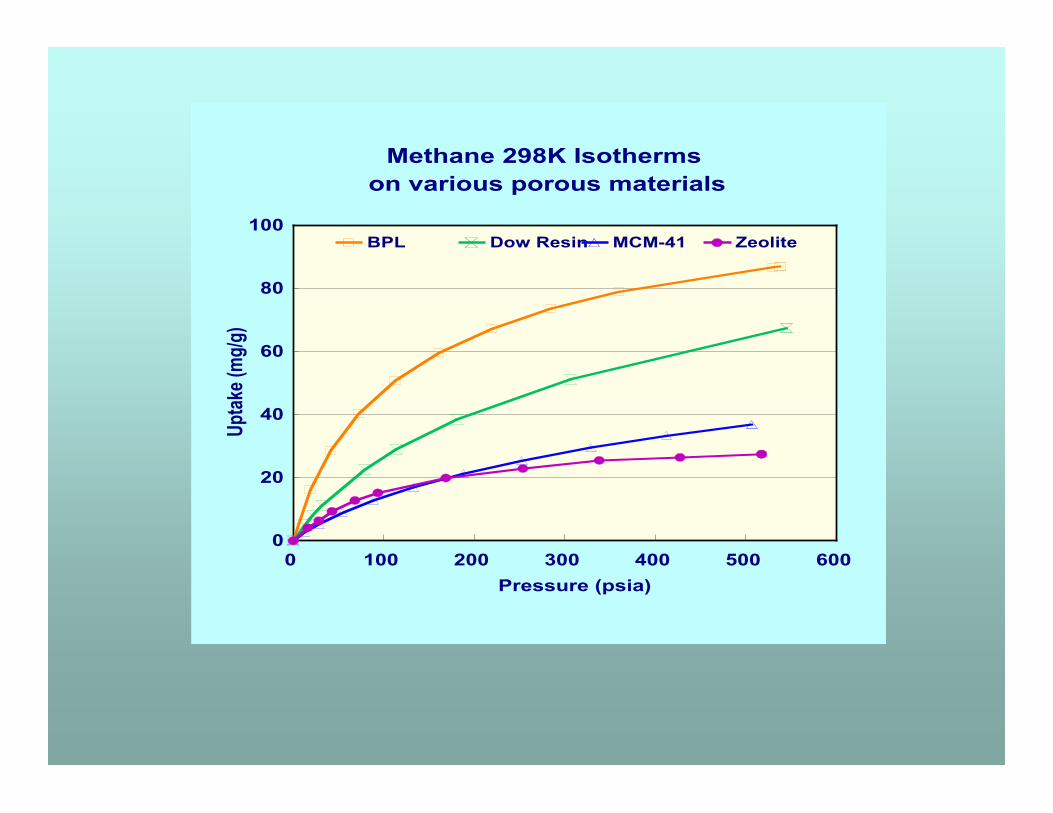
2. Adsorption potential of surface
Different materials give different 298Kmethane isotherms.
Porous organic compounds,e.g. Amberlite (Rohm & Haas), Dow resins
Zeolites, (Davidson molecular sieves)
Silica based compounds,Xerogels, aerogels, MCM41 etc.
All adsorb less methane than similar areaporous carbon.
They have lower adsorption potentials.
0
20
40
60
80
100 Up
take (
mg/g)
0 100 200 300 400 500 600 Pressure (psia)
BPL Dow Resin MCM-41 Zeolite
Methane 298K Isothermson various porous materials
However,
Some high methane uptake claims made for
cavity based crystalline salts.
Ni++ Cu++ salts by Seki, Osaka Gas
Zn++ salts by Yaghi, University of Michigan
Never independently verified.
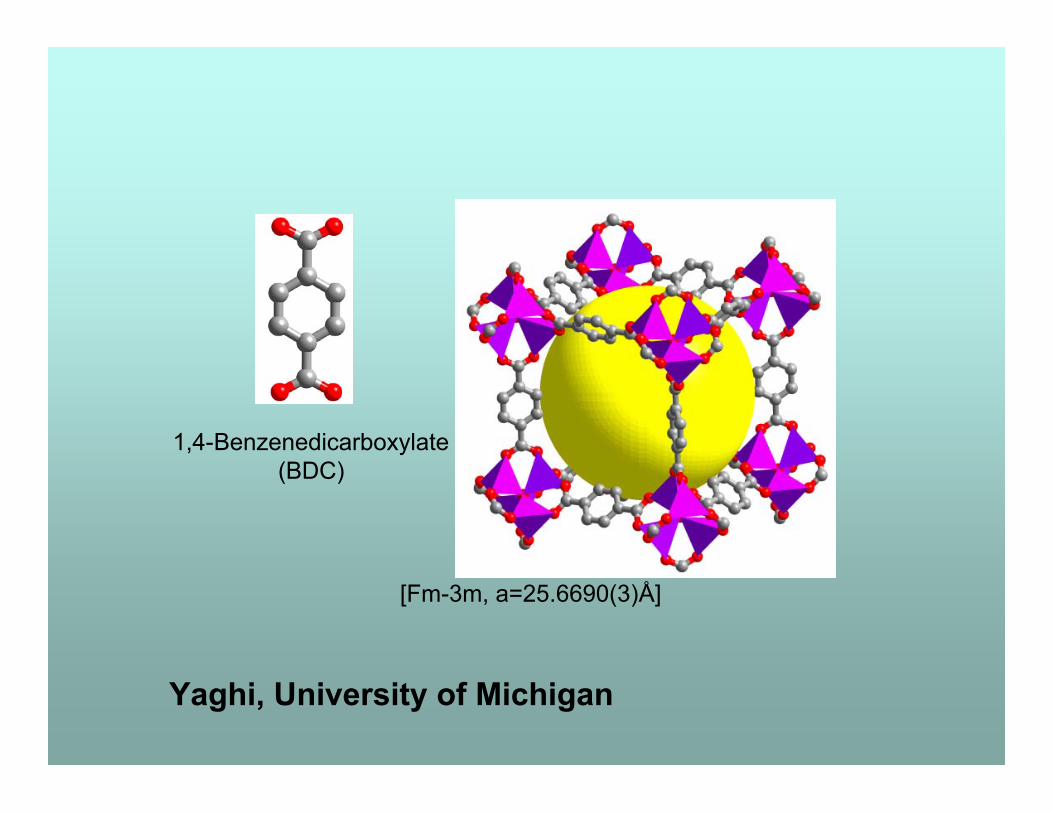
[Fm-3m, a=25.6690(3)Å]
1,4-Benzenedicarboxylate(BDC)
Yaghi, University of Michigan
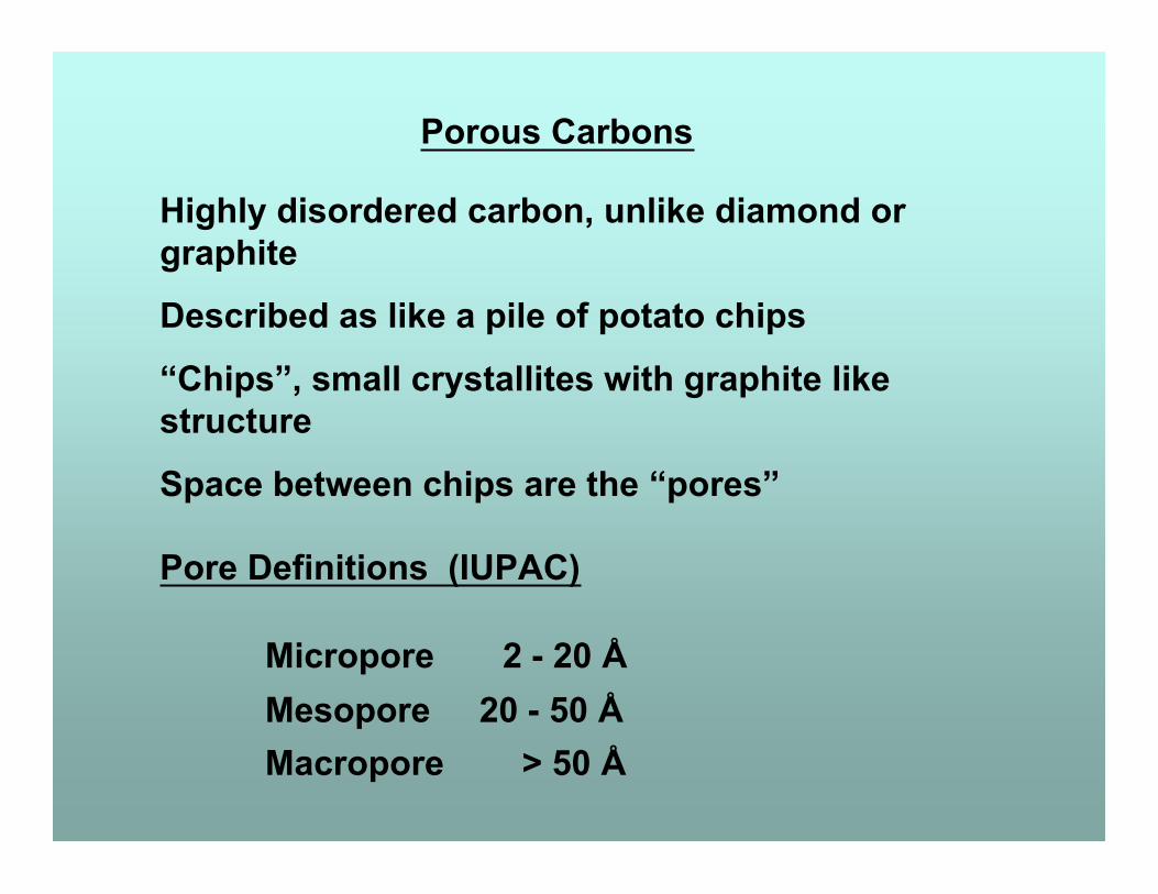
Porous Carbons
Highly disordered carbon, unlike diamond orgraphite
Described as like a pile of potato chips
“Chips”, small crystallites with graphite likestructure
Space between chips are the “pores”
Pore Definitions (IUPAC)
Micropore 2 - 20 ÅMesopore 20 - 50 ÅMacropore > 50 Å
Adsorption
Pore wall of carbon atoms provides attractive
force for the adsorbate molecules.
Influence of both “walls” in narrow pores
so adsorption potential is greater.
Rule of thumb,
Narrow pored adsorbents, good for gas
adsorption, small molecules.
Larger pored materials, better for liquids
and larger sized molecules.
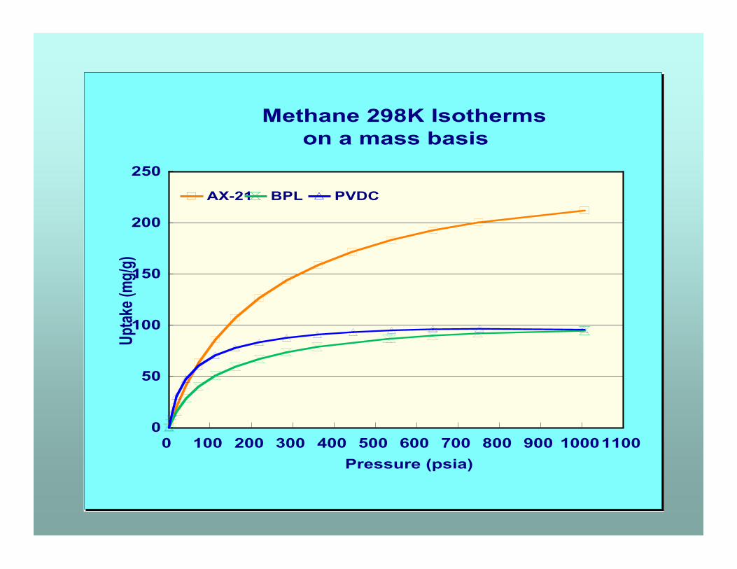
0
50
100
150
200
250
Uptak
e (mg
/g)
0 100 200 300 400 500 600 700 800 900 1000 1100 Pressure (psia)
AX-21 BPL PVDC
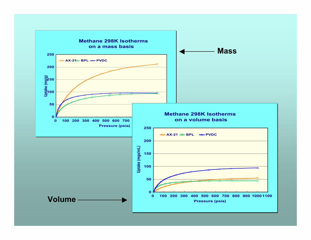
Methane 298K Isotherms on a mass basis
Gas Storage
Adsorption uptakes usually expressed as
mass uptake,
e.g. Grams adsorbate / gram adsorbent
Porous carbons differ greatly in density.
Storage vessels have finite volume.
For storage, uptake must be considered
from a volume perspective.
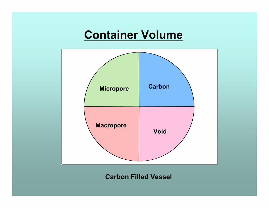
Container Volume
Carbon
Void
Micropore
Macropore
Carbon Filled Vessel
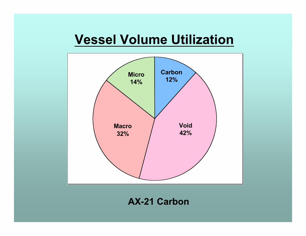
Vessel Volume Utilization
AX-21 Carbon
Carbon12%
Micro14%
Void42%
Macro32%
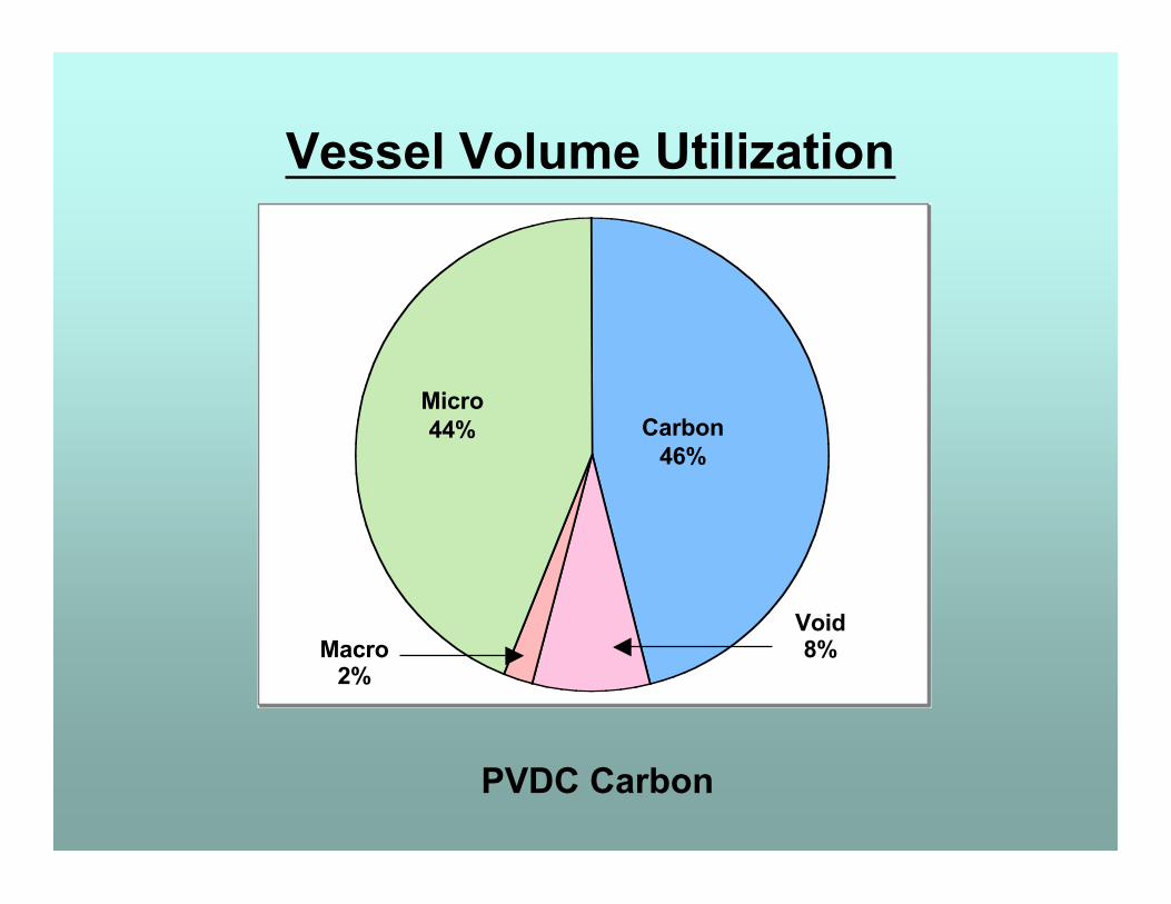
Vessel Volume Utilization
PVDC Carbon
Carbon46%
Micro44%
Void8%Macro
2%
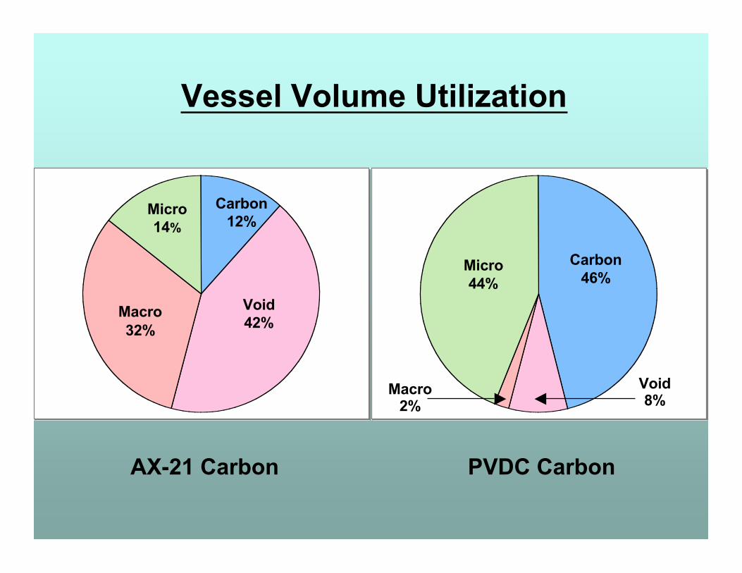
AX-21 Carbon PVDC Carbon
Vessel Volume Utilization
Carbon12%
Void42%
Macro32%
Micro14%
Carbon46%
Micro44%
Void8%
Macro2%

0
50
100
150
200
250
Uptak
e (mg
s/mL)
0 100 200 300 400 500 600 700 800 900 1000 1100 Pressure (psia)
AX-21 BPL PVDC
Methane 298K Isothermson a volume basis
0
50
100
150
200
250
Uptak
e (mg
/g)
0 100 200 300 400 500 600 700 800 900 1000 1100 Pressure (psia)
AX-21 BPL PVDC
Methane 298K Isotherms on a mass basis
0
50
100
150
200
250
Uptak
e (mg
s/mL)
0 100 200 300 400 500 600 700 800 900 1000 1100 Pressure (psia)
AX-21 BPL PVDC
Methane 298K Isothermson a volume basis
Mass
Volume
Volumetric Storage
Maximise micropore volume in vessel
Minimise void space in vessel
Density of molecules in macropore nearly
the same as the gas phase,
so carbon adsorbent should have as few
macropores as possible.
Some mesopore structure needed to aid
kinetics of adsorption / desorption.
Natural Gas Storage
Natural Gas Vehicles
CNG Tanks, Heavy wall cylindrical steel
Gas compressed to 3000 psi (21 MPa)store / deliver ~220 V/V
ANG Tanks, Extruded aluminum
Carbon monolith filled tank at 500 psistore 185 V/V, deliver ~150 V/V
ANG at 1/6 the pressure store 85%, deliver 70% that of CNG
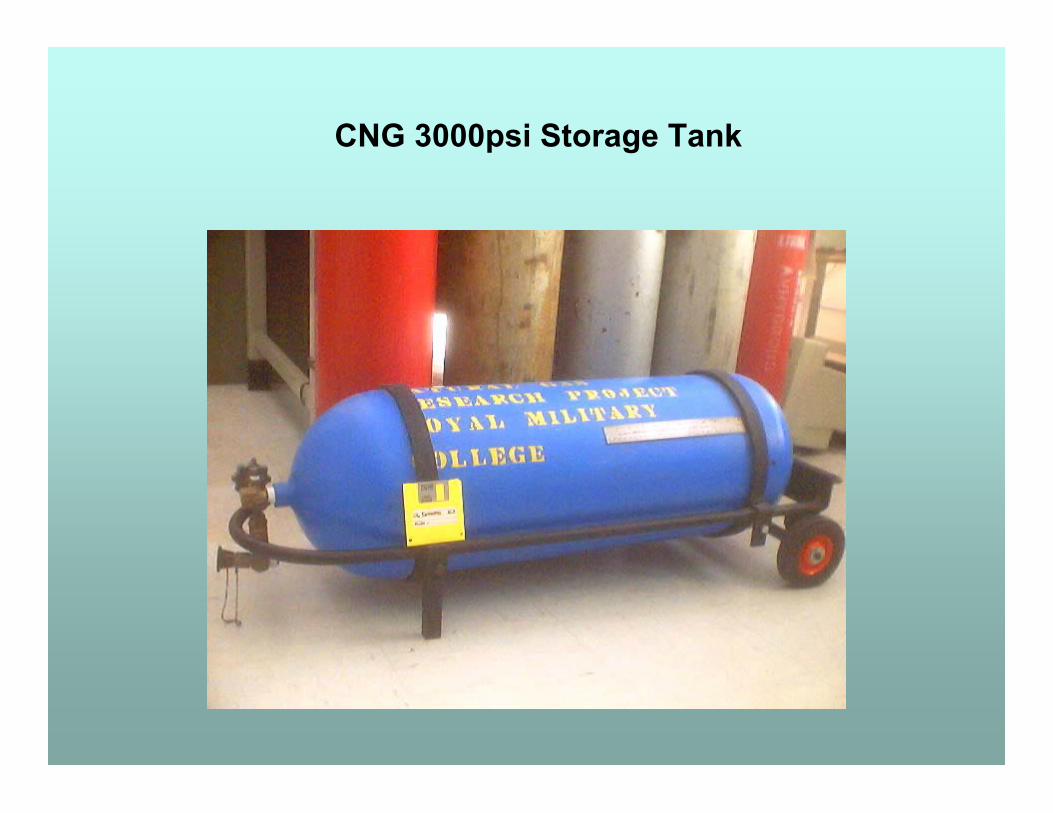
CNG 3000psi Storage Tank
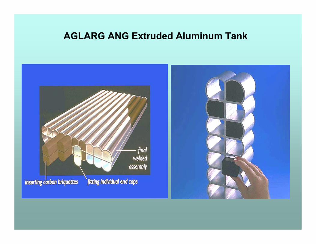
AGLARG ANG Extruded Aluminum Tank
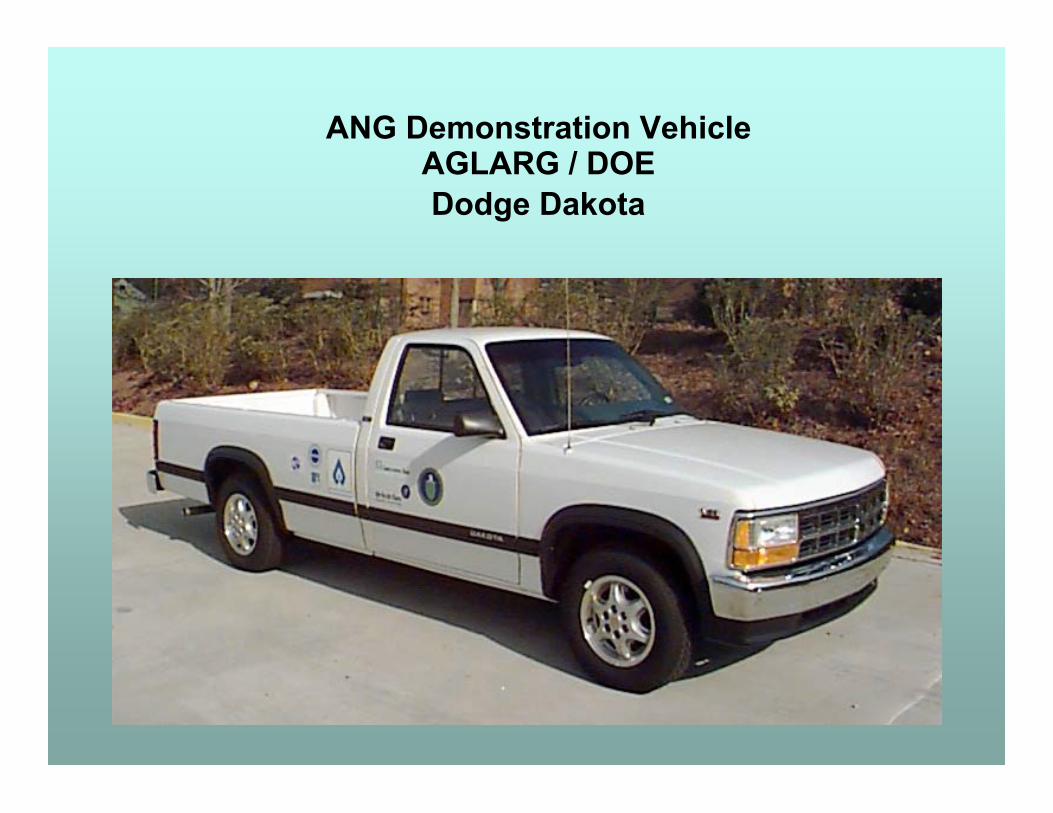
ANG Demonstration VehicleAGLARG / DOEDodge Dakota
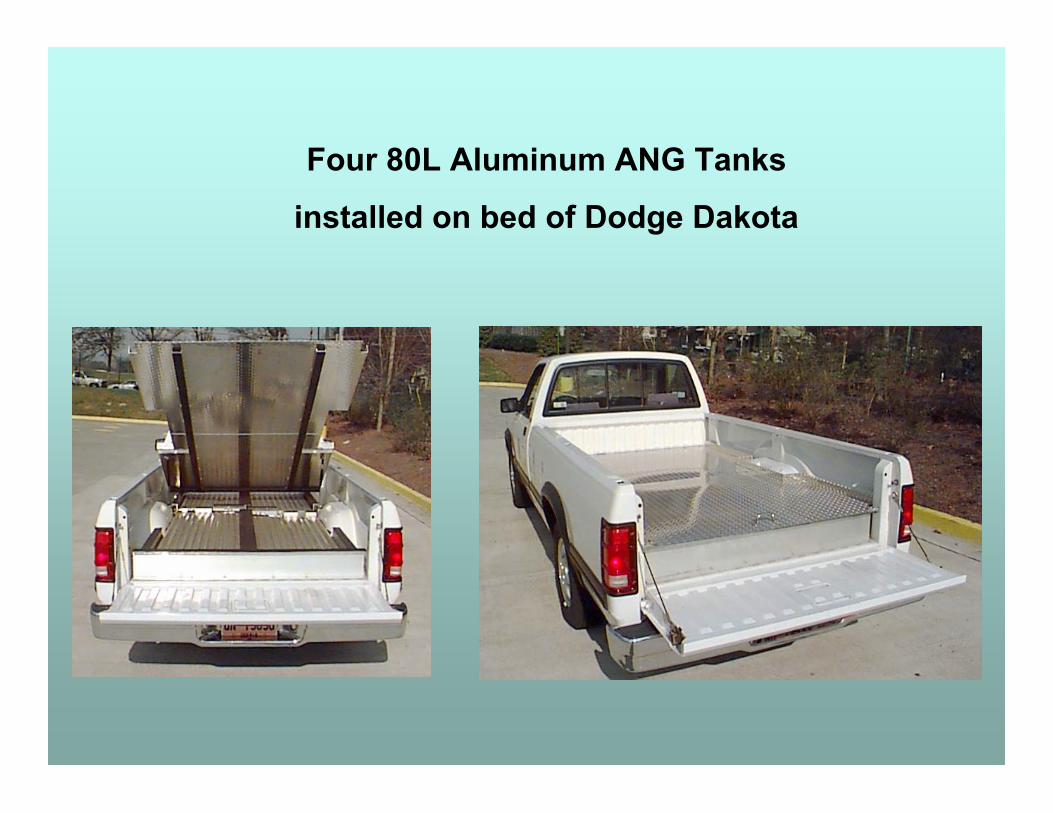
Four 80L Aluminum ANG Tanks
installed on bed of Dodge Dakota
0
50
100
150
200
250
0 5 10 15 20
Pressure (MPa)
V/V
De
live
red
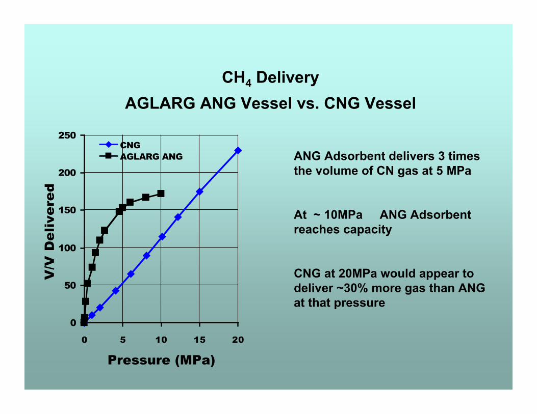
CNGAGLARG ANG ANG Adsorbent delivers 3 times
the volume of CN gas at 5 MPa
At ~ 10MPa ANG Adsorbentreaches capacity
CNG at 20MPa would appear todeliver ~30% more gas than ANGat that pressure
CH4 DeliveryAGLARG ANG Vessel vs. CNG Vessel
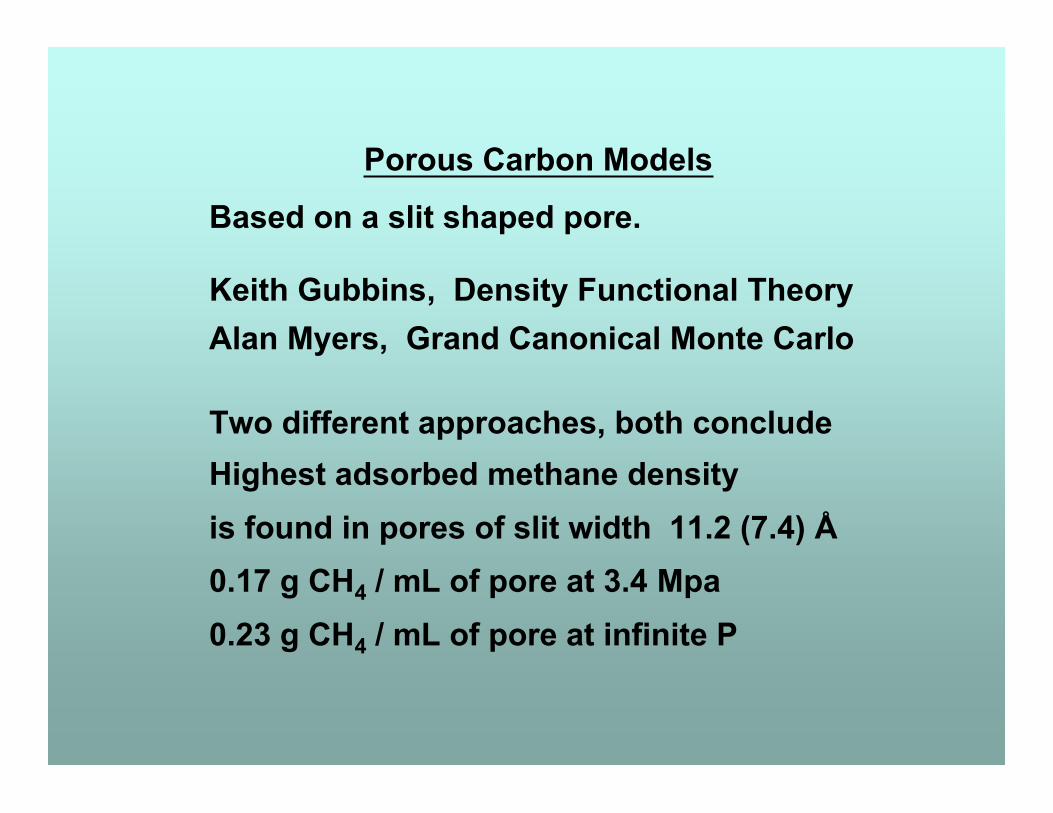
Porous Carbon Models
Based on a slit shaped pore.
Keith Gubbins, Density Functional TheoryAlan Myers, Grand Canonical Monte Carlo
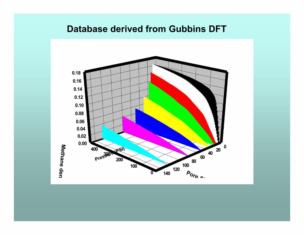
Two different approaches, both concludeHighest adsorbed methane densityis found in pores of slit width 11.2 (7.4) Å0.17 g CH4 / mL of pore at 3.4 Mpa0.23 g CH4 / mL of pore at infinite P
0.000.020.040.060.080.100.120.140.160.18
0100
200300
400 0204060
80100
120140
Methane density (g/m
L)
Pressure (PSI)
Pore Size [A]
Database derived from Gubbins DFT
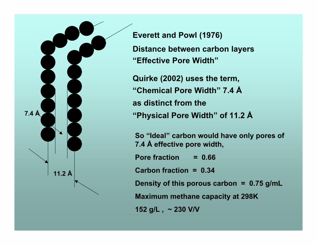
11.2 Å
7.4 Å
Everett and Powl (1976)Distance between carbon layers“Effective Pore Width”
Quirke (2002) uses the term,“Chemical Pore Width” 7.4 Åas distinct from the“Physical Pore Width” of 11.2 Å
So “Ideal” carbon would have only pores of7.4 Å effective pore width,
Pore fraction = 0.66
Carbon fraction = 0.34
Density of this porous carbon = 0.75 g/mL
Maximum methane capacity at 298K
152 g/L , ~ 230 V/V
Porous Carbons are far from “ideal”
Great range of densities, pore volumes andpore size distribution.
How do we characterise a carbon ?
“Particle Density”
Usually determined by mercury at 1 Bar
“Pack Density”
Density carbon can be packed in storage tank
From these, void volume can be found.
“ 420 Bar mercury Density”
Macropore filled at this pressure.

Vessel Volume Utilization
AX-21 Carbon
Carbon12%
Micro14%
Void42%
Macro32%
Micropore Volume
Various methods in use for determination ofmicropore volume.
Most common, Dubinin-Radushkevich (1947) plotusing the low pressure 77K nitrogen isotherm.Has also been applied to 273K CO2 isotherms.
Very different conditions to relatively highpressure methane at 298K.
These methods only give overall microporevolume but give no clue or indication of the rangeof micropore widths.
Pore Size Distribution
Again, there are several methods used toobtain PSDs, some more widely accepted thanothers.
Mostly determined using 77K nitrogen or 273Kcarbon dioxide low pressure isotherms. Bothsub-critical conditions.
Wide variation in the result depending onmethod.
Unlike nitrogen or carbon dioxide, methane isnon-linear (tetrahedral) and at 298K is super-critical.
298K Methane Pore Size Distribution
Method for determination of porous carbon PSDhas been developed by Sosin and Quinn.
Database derived from Gubbins DFT model for298K methane isotherm at pressures to 3.4 MPa.
Simple to use spreadsheet method forQuattro or Excel, (Solver “add in” needed).
Clearly shows the different PSDs of differentcarbons.Valuble in showing how changes in carbonpreparation affect change in PSD.Useful in determining how close to “ideal” thecarbon sample is.
Strategies for Enhancing NG Storage / Delivery
1. Tank is vital to success
2. Guard bed
3. Monolith
4. Micropore volume
5. Adsorbent preparation
1. Tank
Should possess good box (envelope) characteristics. Must be suitable for packing monoliths.
Internal web structure, not only for strength, but for good heat exchange. Multiple tanks, switchable and programmed to
operate as isothermally as possible.

2. Guard Bed
Impurities in natural gas can build up in the
micropores and over many fill / empty cycles
can result in a decrease in storage capacity.
Water is particularly difficult to desorb.
3. Monolith
Carbon adsorbent should be capable of being
produced as monoliths to minimise void space.
If a binder is used, it should not block
micropores.
Binder should also occupy minimal volume.
4. Micropore Volume
Methane isotherm should be used to determine micropore volume.
It should be in excess of 0.7 mL / mL of monolith, since it is unlikely to be all “optimal pore”.
5. Carbon Preparation
Directed towards methods that create new
micropore, not to conventional “activation”
methods which merely enlarge existing pore.
Military Interest in Porous Carbon
Protection from CW agents,
Sarin, VX, mustard, HCN, phosgene etc.
Carbon in respirator canisters and clothing,attempts made to “tailor” carbon for various toxicmolecules.
Difficulties with water saturation in respirators.
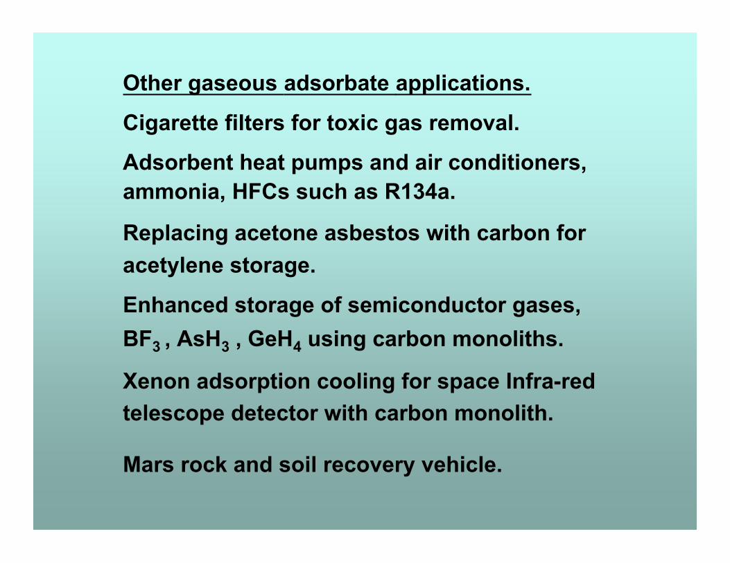
Other gaseous adsorbate applications.
Cigarette filters for toxic gas removal.
Adsorbent heat pumps and air conditioners,ammonia, HFCs such as R134a.
Replacing acetone asbestos with carbon foracetylene storage.
Enhanced storage of semiconductor gases,BF3 , AsH3 , GeH4 using carbon monoliths.
Xenon adsorption cooling for space Infra-redtelescope detector with carbon monolith.
Mars rock and soil recovery vehicle.
Other Uses of Porous carbon
Help !!! I can’t get home !!

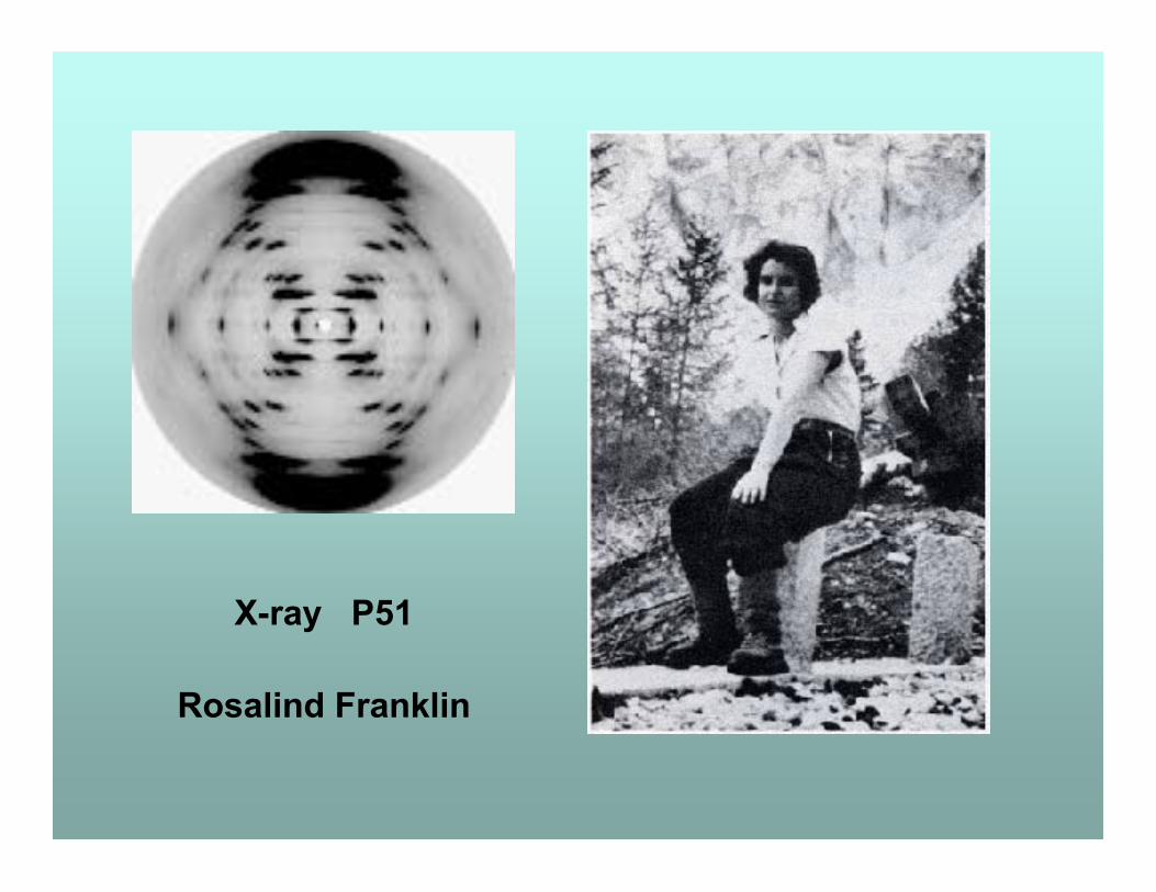
X-ray P51
Rosalind Franklin

John Randall, University College, London
Rosalind Franklin, University College, London
Maurice Wilkins, University College, London
Max Perutz, MRC, Cambridge
Francis Crick, Cambridge University
James Watson, Cambridge University
Aaron Klug, UCL and MRC
Independent Books on Rosalind Franklin by :
Anne Sayre, Brenda Maddox, Lynne Elkin