Embed Size (px)
Citation preview
ADU2
Operation and Reference Manual
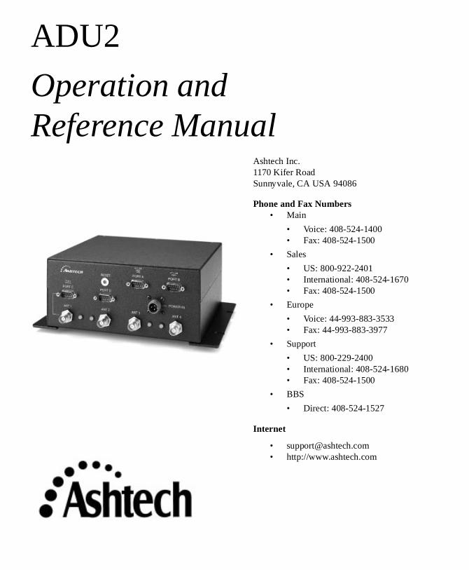
Ashtech Inc.1170 Kifer RoadSunnyvale, CA USA 94086
Phone and Fax Numbers• Main
• Voice: 408-524-1400• Fax: 408-524-1500
• Sales
• US: 800-922-2401• International: 408-524-1670• Fax: 408-524-1500
• Europe
• Voice: 44-993-883-3533• Fax: 44-993-883-3977
• Support
• US: 800-229-2400• International: 408-524-1680• Fax: 408-524-1500
• BBS
• Direct: 408-524-1527
Internet
• [email protected]• http://www.ashtech.com

Page ii
d in ny ise,
ions tion
t
Copyright Notice
All rights reserved. No part of this publication or the computer programs describeit may be reproduced, translated, stored in a retrieval system, or transmitted in aform or by any means, electronic, mechanical photocopying, recording, or otherwwithout prior written permission of Ashtech Inc. Your rights with regard to this publication and the computer programs are subject to the restrictions and limitatimposed by the copyright laws of the United States of America and/or the jurisdicin which you are located.
For information on translations and distribution outside the U.S.A., please contacAshtech Inc.
NO PATENT OR COPYRIGHT LIABILITY IS ASSUMED WITH RESPECT TO THE USE OF INFORMATION CONTAINED HEREIN. WHILE REASONABLE PRECAUTIONS HAVE BEEN TAKEN IN THE PREPARATION OF THIS PUBLICATION, ASHTECH ASSUMES NO RESPONSIBILITY FOR ERRORS OR OMISSIONS, NOR IS ANY LIABILITY ASSUMED FOR DAMAGES RESULTING FROM THE USE OF THE INFORMATION CONTAINED HEREIN. FURTHER, THIS PUBLICATION AND FEATURES DESCRIBED HEREIN ARE SUBJECT TO CHANGE WITHOUT NOTICE.
UNLESS OTHERWISE NOTED, ALL TRADEMARKS USED HEREIN ARE THE PROPERTY OF THE RESPECTIVE COMPANIES.
Printed in the United States of America.
© Copyright December 1996 Ashtech Inc.
Part Number: 630061, Revision B
ADU2 Operation and Reference Manual

d s.
Trademarks
ADU2 and the Ashtech logo are trademarks of Ashtech Inc. All other product anbrand names are trademarks or registered trademarks of their respective holder
Page iii

Page iv
ADU2 Operation and Reference Manual
Table of Contents
Table of Co
Reliance F
undamentals
2
667
122
71
7
0
3
37
Chapter 1. Introduction . . . . . . . . . . . . . . . . . . . . . . . . . . . . . . . . . . . . . . . . . . . . . . 1
How To Use This Manual . . . . . . . . . . . . . . . . . . . . . . . . . . . . . . . . . . . . . . . . . . 1Description . . . . . . . . . . . . . . . . . . . . . . . . . . . . . . . . . . . . . . . . . . . . . . . . . . . . .
Physical Description . . . . . . . . . . . . . . . . . . . . . . . . . . . . . . . . . . . . . . . . . . . 3Standard Equipment . . . . . . . . . . . . . . . . . . . . . . . . . . . . . . . . . . . . . . . . . . . . . . Optional Equipment . . . . . . . . . . . . . . . . . . . . . . . . . . . . . . . . . . . . . . . . . . . . . . . Interfaces . . . . . . . . . . . . . . . . . . . . . . . . . . . . . . . . . . . . . . . . . . . . . . . . . . . . . . .
Chapter 2. Quickstart . . . . . . . . . . . . . . . . . . . . . . . . . . . . . . . . . . . . . . . . . . . . . . 11
Installation . . . . . . . . . . . . . . . . . . . . . . . . . . . . . . . . . . . . . . . . . . . . . . . . . . . . . 1Antenna Calibration . . . . . . . . . . . . . . . . . . . . . . . . . . . . . . . . . . . . . . . . . . . . . . 1
Static Survey . . . . . . . . . . . . . . . . . . . . . . . . . . . . . . . . . . . . . . . . . . . . . . . 1Dynamic Survey . . . . . . . . . . . . . . . . . . . . . . . . . . . . . . . . . . . . . . . . . . . . . 13
Enter Offset Vector Information . . . . . . . . . . . . . . . . . . . . . . . . . . . . . . . . . . . . 14
Chapter 3. Installation . . . . . . . . . . . . . . . . . . . . . . . . . . . . . . . . . . . . . . . . . . . . . . 17
Antenna Installation . . . . . . . . . . . . . . . . . . . . . . . . . . . . . . . . . . . . . . . . . . . . . . 1Software Installation . . . . . . . . . . . . . . . . . . . . . . . . . . . . . . . . . . . . . . . . . . . . . 2Equipment Installation . . . . . . . . . . . . . . . . . . . . . . . . . . . . . . . . . . . . . . . . . . . . 24
Verify Antennas are Tracking Satellites . . . . . . . . . . . . . . . . . . . . . . . 25
Chapter 4. Antenna Calibration . . . . . . . . . . . . . . . . . . . . . . . . . . . . . . . . . . . . . . 27
Static Calibration Procedure . . . . . . . . . . . . . . . . . . . . . . . . . . . . . . . . . . . . . . . 2Collect the Data . . . . . . . . . . . . . . . . . . . . . . . . . . . . . . . . . . . . . . . . . . . . . 27Split the Data . . . . . . . . . . . . . . . . . . . . . . . . . . . . . . . . . . . . . . . . . . . . . . . 29Process the Data . . . . . . . . . . . . . . . . . . . . . . . . . . . . . . . . . . . . . . . . . . . . . 3Adjust relative antenna positions . . . . . . . . . . . . . . . . . . . . . . . . . . . . . . . . 31Enter Relative Antenna Position Vectors Information . . . . . . . . . . . . . . . . 33
Dynamic Calibration Procedure . . . . . . . . . . . . . . . . . . . . . . . . . . . . . . . . . . . . 34Collect the Data . . . . . . . . . . . . . . . . . . . . . . . . . . . . . . . . . . . . . . . . . . . . . 34Determine Relative Antenna Positions . . . . . . . . . . . . . . . . . . . . . . . . . . . 35Enter Relative Antenna Position Vectors Information . . . . . . . . . . . . . . . . 48Dynamic Calibration-Run-Time Parameters . . . . . . . . . . . . . . . . . . . . . . . 48
Chapter 5. Command Response Formats . . . . . . . . . . . . . . . . . . . . . . . . . . . . . . . 5
Overview . . . . . . . . . . . . . . . . . . . . . . . . . . . . . . . . . . . . . . . . . . . . . . . . . . . . . . 5Commands Detailed Descriptions . . . . . . . . . . . . . . . . . . . . . . . . . . . . . . . . . . . 5
Chapter 6. Troubleshooting . . . . . . . . . . . . . . . . . . . . . . . . . . . . . . . . . . . . . . . . . 99
ntents Page v
Page vi
00
33
70
345
8
1
2
Installation and Initialization Problems . . . . . . . . . . . . . . . . . . . . . . . . . . . . . . 99No power at the receiver . . . . . . . . . . . . . . . . . . . . . . . . . . . . . . . . . . . . . . 99No communication response from the receiver . . . . . . . . . . . . . . . . . . . . . 99
Position and Attitude Measurement Problems . . . . . . . . . . . . . . . . . . . . . . . . 10Receiver does not compute position . . . . . . . . . . . . . . . . . . . . . . . . . . . . 10Causes for Bad Antennas or Low SNRs . . . . . . . . . . . . . . . . . . . . . . . . . 100Receiver computes position but not attitude . . . . . . . . . . . . . . . . . . . . . . 101Noisy attitude data . . . . . . . . . . . . . . . . . . . . . . . . . . . . . . . . . . . . . . . . . . 102
Notes on Attitude Data . . . . . . . . . . . . . . . . . . . . . . . . . . . . . . . . . . . . . . . . . . 10Antenna Separations . . . . . . . . . . . . . . . . . . . . . . . . . . . . . . . . . . . . . . . . 10Attitude Quality Indicators . . . . . . . . . . . . . . . . . . . . . . . . . . . . . . . . . . . 103
Chapter 7. ADULOG . . . . . . . . . . . . . . . . . . . . . . . . . . . . . . . . . . . . . . . . . . . . . 105
Operating ADULOG . . . . . . . . . . . . . . . . . . . . . . . . . . . . . . . . . . . . . . . . . . . 105Logging Data . . . . . . . . . . . . . . . . . . . . . . . . . . . . . . . . . . . . . . . . . . . . . . . . . 10Graphical Representation . . . . . . . . . . . . . . . . . . . . . . . . . . . . . . . . . . . . . . . . 11ADULOG Options . . . . . . . . . . . . . . . . . . . . . . . . . . . . . . . . . . . . . . . . . . . . . 112
Almanac downloading . . . . . . . . . . . . . . . . . . . . . . . . . . . . . . . . . . . . . . . 112Statistics . . . . . . . . . . . . . . . . . . . . . . . . . . . . . . . . . . . . . . . . . . . . . . . . . . 11
Autonomous Mode . . . . . . . . . . . . . . . . . . . . . . . . . . . . . . . . . . . . . . . . . . . . . 11Logging parameters . . . . . . . . . . . . . . . . . . . . . . . . . . . . . . . . . . . . . . . . . 11
Start_Time . . . . . . . . . . . . . . . . . . . . . . . . . . . . . . . . . . . . . . . . . . . . 115End_Time . . . . . . . . . . . . . . . . . . . . . . . . . . . . . . . . . . . . . . . . . . . . . 115Template . . . . . . . . . . . . . . . . . . . . . . . . . . . . . . . . . . . . . . . . . . . . . . 116Calibration . . . . . . . . . . . . . . . . . . . . . . . . . . . . . . . . . . . . . . . . . . . . 116Interval . . . . . . . . . . . . . . . . . . . . . . . . . . . . . . . . . . . . . . . . . . . . . . . 116Elevation_Mask . . . . . . . . . . . . . . . . . . . . . . . . . . . . . . . . . . . . . . . . 116Min_SV . . . . . . . . . . . . . . . . . . . . . . . . . . . . . . . . . . . . . . . . . . . . . . 116Ref_Day . . . . . . . . . . . . . . . . . . . . . . . . . . . . . . . . . . . . . . . . . . . . . . 116Day_Offset . . . . . . . . . . . . . . . . . . . . . . . . . . . . . . . . . . . . . . . . . . . . 117Second_B_File . . . . . . . . . . . . . . . . . . . . . . . . . . . . . . . . . . . . . . . . . 117
Working in autonomous mode . . . . . . . . . . . . . . . . . . . . . . . . . . . . . . . . 117File Formats . . . . . . . . . . . . . . . . . . . . . . . . . . . . . . . . . . . . . . . . . . . . . . . . . . 11
B-file Format . . . . . . . . . . . . . . . . . . . . . . . . . . . . . . . . . . . . . . . . . . . . . . 118E-file Format . . . . . . . . . . . . . . . . . . . . . . . . . . . . . . . . . . . . . . . . . . . . . . 120A-file Format . . . . . . . . . . . . . . . . . . . . . . . . . . . . . . . . . . . . . . . . . . . . . . 121
Antenna Cables . . . . . . . . . . . . . . . . . . . . . . . . . . . . . . . . . . . . . . . . . . . . . . . . A-
Appendix A. Antennas and Cabling . . . . . . . . . . . . . . . . . . . . . . . . . . . . . . . . . . . A-1
Geodetic Antenna . . . . . . . . . . . . . . . . . . . . . . . . . . . . . . . . . . . . . . . . . . . . . . A-Aircraft Antenna . . . . . . . . . . . . . . . . . . . . . . . . . . . . . . . . . . . . . . . . . . . . . . . A-3Marine Antenna . . . . . . . . . . . . . . . . . . . . . . . . . . . . . . . . . . . . . . . . . . . . . . . A-4Fixed Portable Antenna Array . . . . . . . . . . . . . . . . . . . . . . . . . . . . . . . . . . . . A-5
ADU2 Operations and Reference Manual
Table of Co
A-5
B-1
B-1 B-2. B-3 B-5
. C-1
. C-1. C-4 C-4-4
. C-5C-5C-5 C-6
-6C-6 . C-6-6
C-6 C-7 C-7. C-7 C-7 C-7. C-8
ex-1
Fixed Portable Antenna Array Installation . . . . . . . . . . . . . . . . . . . . . . . .
Appendix B. Performance Improvement . . . . . . . . . . . . . . . . . . . . . . . . . . . . . . . .
Attitude Accuracy . . . . . . . . . . . . . . . . . . . . . . . . . . . . . . . . . . . . . . . . . . . . . .Attitude Offset Angles . . . . . . . . . . . . . . . . . . . . . . . . . . . . . . . . . . . . . . . . . . .Attitude Error Sources . . . . . . . . . . . . . . . . . . . . . . . . . . . . . . . . . . . . . . . . . . Attitude Quality Indicators . . . . . . . . . . . . . . . . . . . . . . . . . . . . . . . . . . . . . . .
Appendix C. Reference . . . . . . . . . . . . . . . . . . . . . . . . . . . . . . . . . . . . . . . . . . . .
Common GPS Acronyms . . . . . . . . . . . . . . . . . . . . . . . . . . . . . . . . . . . . . . . GPSIG Information . . . . . . . . . . . . . . . . . . . . . . . . . . . . . . . . . . . . . . . . . . . .
GPSIC Voice Recording . . . . . . . . . . . . . . . . . . . . . . . . . . . . . . . . . . . . .WWV/WWVH Voice Broadcasts . . . . . . . . . . . . . . . . . . . . . . . . . . . . . . CUS Coast Guard Broadcast to Mariners . . . . . . . . . . . . . . . . . . . . . . . . . GPSIC Computer Bulletin Board Service (BBS) . . . . . . . . . . . . . . . . . . . Defense Mapping Agency (ANMS) . . . . . . . . . . . . . . . . . . . . . . . . . . . . . DMA Broadcast Warnings . . . . . . . . . . . . . . . . . . . . . . . . . . . . . . . . . . . .DMA Weekly Notice to Mariners . . . . . . . . . . . . . . . . . . . . . . . . . . . . . . CNAVTEX Text Broadcast . . . . . . . . . . . . . . . . . . . . . . . . . . . . . . . . . . . .
Sources . . . . . . . . . . . . . . . . . . . . . . . . . . . . . . . . . . . . . . . . . . . . . . . . . . . . .National Geodetic Information Center, NOAA . . . . . . . . . . . . . . . . . . . . CInstitute of Navigation . . . . . . . . . . . . . . . . . . . . . . . . . . . . . . . . . . . . . . .Scripps Orbit and Permanent Array Center (SOPAC) . . . . . . . . . . . . . . .International GPS Service for Geodynamics (IGS) . . . . . . . . . . . . . . . . .Reference Books on GPS Theory . . . . . . . . . . . . . . . . . . . . . . . . . . . . . . Mathematical Treatment . . . . . . . . . . . . . . . . . . . . . . . . . . . . . . . . . . . . .Overview of Geodesy . . . . . . . . . . . . . . . . . . . . . . . . . . . . . . . . . . . . . . . .White Papers . . . . . . . . . . . . . . . . . . . . . . . . . . . . . . . . . . . . . . . . . . . . .
Index . . . . . . . . . . . . . . . . . . . . . . . . . . . . . . . . . . . . . . . . . . . . . . . . . . . . . . . . Ind
ntents Page vii

Page viii
ADU2 Operations and Reference Manual
List of Figures
List of Figu
Reliance F
undamentals
Figure 1.1: Attitude Components . . . . . . . . . . . . . . . . . . . . . . . . . . . . . . . . . . . 3 Figure 1.2: ADU2 Front Panel . . . . . . . . . . . . . . . . . . . . . . . . . . . . . . . . . . . . . 4 Figure 1.3: Port A Pin Assignments . . . . . . . . . . . . . . . . . . . . . . . . . . . . . . . . . 7 Figure 1.4: Port B Pin Assignments . . . . . . . . . . . . . . . . . . . . . . . . . . . . . . . . . 8 Figure 1.5: Port C Pin Assignments . . . . . . . . . . . . . . . . . . . . . . . . . . . . . . . . . 8 Figure 1.6: Port D Pin Assignments . . . . . . . . . . . . . . . . . . . . . . . . . . . . . . . . . 9 Figure 1.7: Null Modem Data Cable . . . . . . . . . . . . . . . . . . . . . . . . . . . . . . . . . 9 Figure 1.8: ADU2 Power Connector with Fuse Holder . . . . . . . . . . . . . . . . . 10 Figure 2.1: Antenna locations on an aircraft . . . . . . . . . . . . . . . . . . . . . . . . . . 12 Figure 3.1: Configurations of Antennas (Top View) . . . . . . . . . . . . . . . . . . . 19 Figure 3.2: Suggested Locations for Antennas on Aircraft. . . . . . . . . . . . . . . 20 Figure 3.3: ADU2 Unit with Mounting Brackets . . . . . . . . . . . . . . . . . . . . . . 24 Figure 4.1: ADU2 B-File Selection. . . . . . . . . . . . . . . . . . . . . . . . . . . . . . . . . 29 Figure 4.2: Relative Antenna Position Rotation Methods. . . . . . . . . . . . . . . . 31 Figure 4.3: Relative Antenna Position Rotation Methods. . . . . . . . . . . . . . . . 32 Figure 4.4: Select B-File for Calibration. . . . . . . . . . . . . . . . . . . . . . . . . . . . . 35 Figure 4.5: Calibration Program Options . . . . . . . . . . . . . . . . . . . . . . . . . . . . 36 Figure 4.6: Determine Good Period of Data . . . . . . . . . . . . . . . . . . . . . . . . . . 37 Figure 4.7: Determine Good Period of Data . . . . . . . . . . . . . . . . . . . . . . . . . . 38 Figure 4.8: Prepare Double Difference Data. . . . . . . . . . . . . . . . . . . . . . . . . . 39 Figure 4.9: Kalman Filtering and Ambiguity Search . . . . . . . . . . . . . . . . . . . 40 Figure 4.10: Ambiguity Search Example . . . . . . . . . . . . . . . . . . . . . . . . . . . . . 41 Figure 4.11: Ambiguity Search Warning . . . . . . . . . . . . . . . . . . . . . . . . . . . . . 42 Figure 4.12: Compute Body Reference Frame Vectors . . . . . . . . . . . . . . . . . . 44 Figure 4.13: Computing Body Reference Frame Vectors. . . . . . . . . . . . . . . . . 45 Figure 4.14: BRF Vectors Plot . . . . . . . . . . . . . . . . . . . . . . . . . . . . . . . . . . . . . 47 Figure 4.14: Run-Time Parameters . . . . . . . . . . . . . . . . . . . . . . . . . . . . . . . . . . 49 Figure 7.1: ADULOG Main Screen . . . . . . . . . . . . . . . . . . . . . . . . . . . . . . . 106 Figure 7.2: ADULOG Logging Table . . . . . . . . . . . . . . . . . . . . . . . . . . . . . . 109 Figure 7.3: ADULOG Compass . . . . . . . . . . . . . . . . . . . . . . . . . . . . . . . . . . 111 Figure 7.4: ADULOG Horizon Representation . . . . . . . . . . . . . . . . . . . . . . 111 Figure A.1: Geodetic Antenna . . . . . . . . . . . . . . . . . . . . . . . . . . . . . . . . . . . . A-2 Figure A.2: Aircraft Antenna . . . . . . . . . . . . . . . . . . . . . . . . . . . . . . . . . . . . . A-3 Figure A.3: Marine Antenna . . . . . . . . . . . . . . . . . . . . . . . . . . . . . . . . . . . . . A-4 Figure A.4: Recommended Placement of Sealing Compound on Cross Arm
Fittings . . . . . . . . . . . . . . . . . . . . . . . . . . . . . . . . . . . . . . . . . A-5 Figure A.5: Cross Arm Fitting with Engraved Number and Description . . . A-6 Figure A.6: Placing the Cross Arm in the Base Fitting . . . . . . . . . . . . . . . . . A-7
res Page ix
Page x
Figure A.7: Alignment of Cable Port, Cross Arm, and Antenna Bolt. . . . . . A-8 Figure A.8: Completed Fixed Portable Antenna Array . . . . . . . . . . . . . . . . . A-9 Figure B.1: Angle Accuracy vs. Antenna Separation . . . . . . . . . . . . . . . . . . B-1 Figure B.2: Antenna Offset Angle . . . . . . . . . . . . . . . . . . . . . . . . . . . . . . . . B-3
ADU2 Operations and Reference Manual
List of Tables
List of Tab
Reliance F
undamentals
8
Table 1.1: ADU2 Front Panel Components . . . . . . . . . . . . . . . . . . . . . . . . . . . 4 Table 1.2: Technical Specifications of the ADU2 . . . . . . . . . . . . . . . . . . . . . . 5 Table 1.3: Fuse Types . . . . . . . . . . . . . . . . . . . . . . . . . . . . . . . . . . . . . . . . . . 10 Table 2.1: Relative Antenna Position Vectors for Static Survey. . . . . . . . . . 13 Table 2.2: Relative Antenna Position Vectors for Dynamic Survey . . . . . . . 13 Table 2.3: Relative Antenna Position Vectors for the Ashtech Fixed Portable
Antenna Array. . . . . . . . . . . . . . . . . . . . . . . . . . . . . . . . . . . . . 14 Table 3.1: Antenna Placement Suggestions . . . . . . . . . . . . . . . . . . . . . . . . . . 17 Table 3.2: Software Files in the ADU Directory . . . . . . . . . . . . . . . . . . . . . . 22 Table 4.1: Static Calibration Times . . . . . . . . . . . . . . . . . . . . . . . . . . . . . . . . 28 Table 4.2: Relative Antenna Position Vectors . . . . . . . . . . . . . . . . . . . . . . . . 32 Table 4.3: Input Relative Antenna Position Vectors . . . . . . . . . . . . . . . . . . . 47 Table 4.4: Run-Time Parameters Descriptions . . . . . . . . . . . . . . . . . . . . . . . 49 Table 5.1: Command Summary . . . . . . . . . . . . . . . . . . . . . . . . . . . . . . . . . . . 54 Table 5.2: AT2 Data in ASCII Format . . . . . . . . . . . . . . . . . . . . . . . . . . . . . 57 Table 5.3: AT2 Data in Binary Format . . . . . . . . . . . . . . . . . . . . . . . . . . . . . 58 Table 5.4: Attitude Data in ASCII Format. . . . . . . . . . . . . . . . . . . . . . . . . . . 58 Table 5.5: Attitude Data in Binary Format . . . . . . . . . . . . . . . . . . . . . . . . . . 59 Table 5.6: DSO Data in ASCII Format . . . . . . . . . . . . . . . . . . . . . . . . . . . . . 59 Table 5.7: DSO Data in Binary Format . . . . . . . . . . . . . . . . . . . . . . . . . . . . . 60 Table 5.8: MBEN Data in ASCII. . . . . . . . . . . . . . . . . . . . . . . . . . . . . . . . . . 61 Table 5.9: MBEN Data in Binary . . . . . . . . . . . . . . . . . . . . . . . . . . . . . . . . . 63 Table 5.10: PBEN Data in ASCII Format . . . . . . . . . . . . . . . . . . . . . . . . . . . . 65 Table 5.11: PBEN Data in Binary Format . . . . . . . . . . . . . . . . . . . . . . . . . . . . 65 Table 5.12: PSAT Data in ASCII Format . . . . . . . . . . . . . . . . . . . . . . . . . . . . 66 Table 5.13: PSAT Data in Binary Format . . . . . . . . . . . . . . . . . . . . . . . . . . . . 67 Table 5.14: RTC Message Structure . . . . . . . . . . . . . . . . . . . . . . . . . . . . . . . . 69 Table 5.15: SNAV Data . . . . . . . . . . . . . . . . . . . . . . . . . . . . . . . . . . . . . . . . . . 69 Table 5.16: Kalman Filter Parameters . . . . . . . . . . . . . . . . . . . . . . . . . . . . . . . 72 Table 5.17: Kalman Filter Parameters . . . . . . . . . . . . . . . . . . . . . . . . . . . . . . . 74 Table 5.18: Almanac Message . . . . . . . . . . . . . . . . . . . . . . . . . . . . . . . . . . . . . 76 Table 5.19: NMEA DAL Structure . . . . . . . . . . . . . . . . . . . . . . . . . . . . . . . . . 77 Table 5.20: $GPGGA Response Messages . . . . . . . . . . . . . . . . . . . . . . . . . . . 7 Table 5.21: Latitude/Longitude for Position . . . . . . . . . . . . . . . . . . . . . . . . . . 79 Table 5.22: Satellite Range Residuals . . . . . . . . . . . . . . . . . . . . . . . . . . . . . . . 80 Table 5.23: DOP and Satellites Being Tracked . . . . . . . . . . . . . . . . . . . . . . . . 81 Table 5.24: SNR of GPS Satellites Being Tracked . . . . . . . . . . . . . . . . . . . . . 81 Table 5.25: Satellites Tracked and PDOP Message. . . . . . . . . . . . . . . . . . . . . 82
les Page xi
Page xii
Table 5.26: Satellites Tracked. . . . . . . . . . . . . . . . . . . . . . . . . . . . . . . . . . . . . 83 Table 5.27: Present Position Fix with Time of Fix . . . . . . . . . . . . . . . . . . . . . 84 Table 5.28: HDT: Heading . . . . . . . . . . . . . . . . . . . . . . . . . . . . . . . . . . . . . . . 84 Table 5.29: RTCM Message . . . . . . . . . . . . . . . . . . . . . . . . . . . . . . . . . . . . . . 85 Table 5.30: Position and Attitude Message. . . . . . . . . . . . . . . . . . . . . . . . . . . 86 Table 5.31: Position Messages . . . . . . . . . . . . . . . . . . . . . . . . . . . . . . . . . . . . 87 Table 5.32: RRE Structure . . . . . . . . . . . . . . . . . . . . . . . . . . . . . . . . . . . . . . . 89 Table 5.33: Typical RRE Response . . . . . . . . . . . . . . . . . . . . . . . . . . . . . . . . 89 Table 5.34: Satellite Information Messages Structure . . . . . . . . . . . . . . . . . . 90 Table 5.35: Satellite Information Messages Structure . . . . . . . . . . . . . . . . . . 91 Table 5.36: Trigger Time Tag Serial Output Message . . . . . . . . . . . . . . . . . . 92 Table 5.37: Trigger Time Tag Serial Output Message . . . . . . . . . . . . . . . . . . 92 Table 5.38: $GPVTG Structure. . . . . . . . . . . . . . . . . . . . . . . . . . . . . . . . . . . . 93 Table 5.39: Position Computation Codes . . . . . . . . . . . . . . . . . . . . . . . . . . . . 95 Table 5.40: Serial Port Baud Rate Codes . . . . . . . . . . . . . . . . . . . . . . . . . . . . 96 Table 7.1: ADULOG Options . . . . . . . . . . . . . . . . . . . . . . . . . . . . . . . . . . . 112 Table 7.2: Almanac File Structure . . . . . . . . . . . . . . . . . . . . . . . . . . . . . . . 113 Table 7.3: ADULOG Logging Parameters . . . . . . . . . . . . . . . . . . . . . . . . . 114 Table 7.4: ADULOG Error Messages. . . . . . . . . . . . . . . . . . . . . . . . . . . . . 115 Table 7.5: B-file Rawheader Structure . . . . . . . . . . . . . . . . . . . . . . . . . . . . 118 Table 7.6: B-file Epoch Rawnav structure . . . . . . . . . . . . . . . . . . . . . . . . . 118 Table 7.7: B-file Rawdata structure . . . . . . . . . . . . . . . . . . . . . . . . . . . . . . 119 Table 7.8: B-file Epoch Rawdata structure . . . . . . . . . . . . . . . . . . . . . . . . . 119 Table 7.9: E-file Structure . . . . . . . . . . . . . . . . . . . . . . . . . . . . . . . . . . . . . . 120 Table 7.10: A-file Structure . . . . . . . . . . . . . . . . . . . . . . . . . . . . . . . . . . . . . 121 Table A.1: Antenna Cable Electrical Specifications . . . . . . . . . . . . . . . . . . A-1 Table A.2: Cross Arm Descriptions . . . . . . . . . . . . . . . . . . . . . . . . . . . . . . . A-6 Table A.3: Input Relative Antenna Position Vectors for the Ashtech Fixed
Portable Antenna Array . . . . . . . . . . . . . . . . . . . . . . . . . . . A-10 Table C.1: Common GPS Acronyms. . . . . . . . . . . . . . . . . . . . . . . . . . . . . . C-1
ADU2 Operations and Reference Manual
1
IntrodIntroduction
uction
Introductio
titude ents 2
and
es a 4
nd
, . a
ns
ded sonal
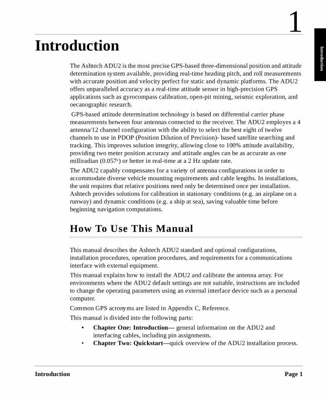
The Ashtech ADU2 is the most precise GPS-based three-dimensional position and atdetermination system available, providing real-time heading pitch, and roll measuremwith accurate position and velocity perfect for static and dynamic platforms. The ADUoffers unparalleled accuracy as a real-time attitude sensor in high-precision GPS applications such as gyrocompass calibration, open-pit mining, seismic exploration, oecanographic research.
GPS-based attitude determination technology is based on differential carrier phase measurements between four antennas connected to the receiver. The ADU2 employantenna/12 channel configuration with the ability to select the best eight of twelve channels to use in PDOP (Position Dilution of Precision)- based satellite searching atracking. This improves solution integrity, allowing close to 100% attitude availability,providing two meter position accuracy and attitude angles can be as accurate as onemilliradian (0.057°) or better in real-time at a 2 Hz update rate.
The ADU2 capably compensates for a variety of antenna configurations in order to accommodate diverse vehicle mounting requirements and cable lengths. In installationsthe unit requires that relative positions need only be determined once per installationAshtech provides solutions for calibration in stationary conditions (e.g. an airplane onrunway) and dynamic conditions (e.g. a ship at sea), saving valuable time before beginning navigation computations.
How To Use This Manual
This manual describes the Ashtech ADU2 standard and optional configurations, installation procedures, operation procedures, and requirements for a communicatiointerface with external equipment.
This manual explains how to install the ADU2 and calibrate the antenna array. For environments where the ADU2 default settings are not suitable, instructions are incluto change the operating parameters using an external interface device such as a percomputer.
Common GPS acronyms are listed in Appendix C, Reference.
This manual is divided into the following parts:
• Chapter One: Introduction— general information on the ADU2 and interfacing cables, including pin assignments.
• Chapter Two: Quickstart—quick overview of the ADU2 installation process.
n Page 1
Page 2
ase
• Chapter Three: Installation Procedure— detailed explanation of the antenna and calibration software installation process.
• Chapter Four: Antenna Calibration — detailed explanation of the static and dynamic calibration program options.
• Chapter Five: Command/Response Formats— command and response formats for the ADU2.
• Chapter Six: Troubleshooting— suggestions for troubleshooting the ADU2 receiver.
• Chapter Seven: ADULOG— detailed explanation on using ADULOG.• Appendix A: Antennas and Cabling— description about and mounting
antennas.• Appendix B: Improving Performance— discussion on attitude accuracy,
offset angles, and error sources.• Appendix C: Reference— listing of common GPS acronyms, GPSIG
information and reference sources used in this manual.
Description
The ADU2 provides real-time attitude information with accurate position and velocity at a half-second rate.
The ADU2 uses four twelve-channel Sensor II GPS receivers to make carrier phmeasurements and perform real-time differential processing. The following measurements are provided up to a half-second rate:
• attitude• position• velocity• time data
ADU2 Operation and Reference Manual
Introductio
Introduction
and
e
by nnect enna.
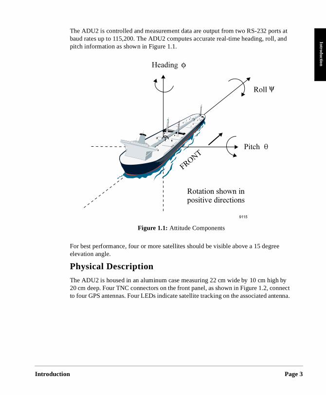
The ADU2 is controlled and measurement data are output from two RS-232 ports at baud rates up to 115,200. The ADU2 computes accurate real-time heading, roll,pitch information as shown in Figure 1.1.
For best performance, four or more satellites should be visible above a 15 degreelevation angle.
Physical Description
The ADU2 is housed in an aluminum case measuring 22 cm wide by 10 cm high20 cm deep. Four TNC connectors on the front panel, as shown in Figure 1.2, coto four GPS antennas. Four LEDs indicate satellite tracking on the associated ant
Figure 1.1: Attitude Components
n Page 3
Page 4
ched
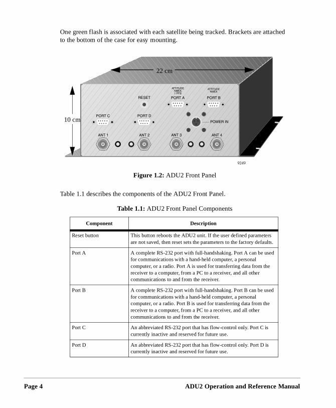
One green flash is associated with each satellite being tracked. Brackets are attato the bottom of the case for easy mounting.Table 1.1 describes the components of the ADU2 Front Panel.
Figure 1.2: ADU2 Front Panel
Table 1.1: ADU2 Front Panel Components
Component Description
Reset button This button reboots the ADU2 unit. If the user defined parameters are not saved, then reset sets the parameters to the factory defaults.
Port A A complete RS-232 port with full-handshaking. Port A can be used for communications with a hand-held computer, a personal computer, or a radio. Port A is used for transferring data from the receiver to a computer, from a PC to a receiver, and all other communications to and from the receiver.
Port B A complete RS-232 port with full-handshaking. Port B can be used for communications with a hand-held computer, a personal computer, or a radio. Port B is used for transferring data from the receiver to a computer, from a PC to a receiver, and all other communications to and from the receiver.
Port C An abbreviated RS-232 port that has flow-control only. Port C is currently inactive and reserved for future use.
Port D An abbreviated RS-232 port that has flow-control only. Port D is currently inactive and reserved for future use.
22 cm
10 cm
ADU2 Operation and Reference Manual
Introductio
Introduction
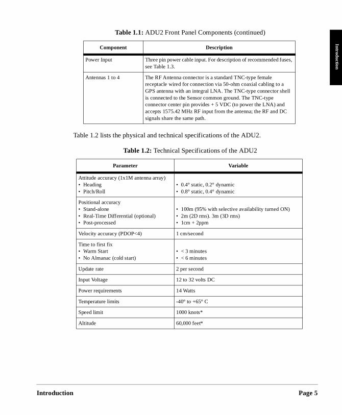
Table 1.2 lists the physical and technical specifications of the ADU2.
Power Input Three pin power cable input. For description of recommended fuses, see Table 1.3.
Antennas 1 to 4 The RF Antenna connector is a standard TNC-type female receptacle wired for connection via 50-ohm coaxial cabling to a GPS antenna with an integral LNA. The TNC-type connector shell is connected to the Sensor common ground. The TNC-type connector center pin provides + 5 VDC (to power the LNA) and accepts 1575.42 MHz RF input from the antenna; the RF and DC signals share the same path.
Table 1.2: Technical Specifications of the ADU2
Parameter Variable
Attitude accuracy (1x1M antenna array)• Heading• Pitch/Roll
• 0.4° static, 0.2° dynamic• 0.8° static, 0.4° dynamic
Positional accuracy • Stand-alone• Real-Time Differential (optional)• Post-processed
• 100m (95% with selective availability turned ON)• 2m (2D rms). 3m (3D rms)• 1cm + 2ppm
Velocity accuracy (PDOP<4) 1 cm/second
Time to first fix• Warm Start• No Almanac (cold start)
• < 3 minutes • < 6 minutes
Update rate 2 per second
Input Voltage 12 to 32 volts DC
Power requirements 14 Watts
Temperature limits -40° to +65° C
Speed limit 1000 knots*
Altitude 60,000 feet*
Table 1.1: ADU2 Front Panel Components (continued)
Component Description
n Page 5
Page 6
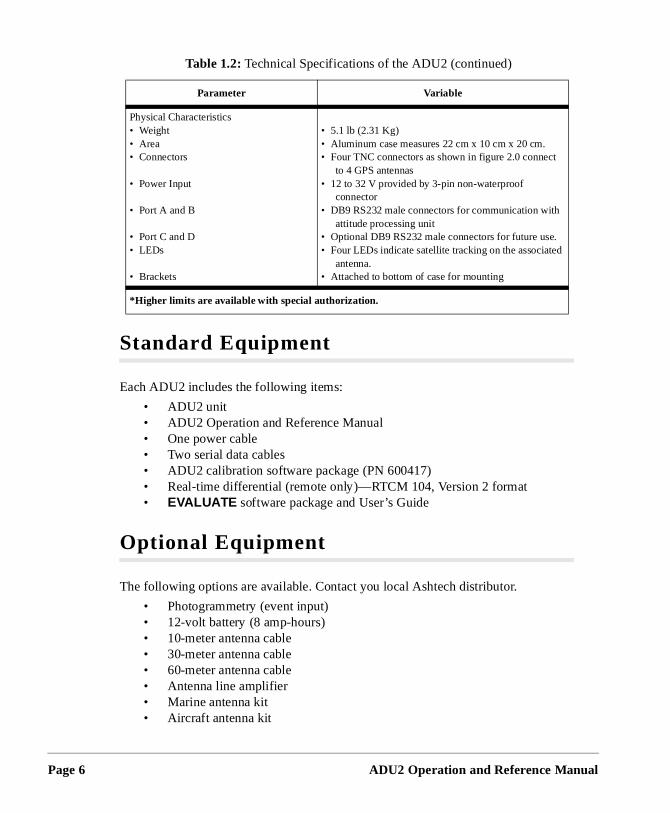
Standard Equipment
Each ADU2 includes the following items:
• ADU2 unit• ADU2 Operation and Reference Manual• One power cable• Two serial data cables• ADU2 calibration software package (PN 600417) • Real-time differential (remote only)—RTCM 104, Version 2 format• EVALUATE software package and User’s Guide
Optional Equipment
The following options are available. Contact you local Ashtech distributor.
• Photogrammetry (event input)• 12-volt battery (8 amp-hours)• 10-meter antenna cable• 30-meter antenna cable• 60-meter antenna cable• Antenna line amplifier• Marine antenna kit• Aircraft antenna kit
Physical Characteristics• Weight• Area• Connectors
• Power Input
• Port A and B
• Port C and D• LEDs
• Brackets
• 5.1 lb (2.31 Kg)• Aluminum case measures 22 cm x 10 cm x 20 cm.• Four TNC connectors as shown in figure 2.0 connect
to 4 GPS antennas• 12 to 32 V provided by 3-pin non-waterproof
connector• DB9 RS232 male connectors for communication with
attitude processing unit• Optional DB9 RS232 male connectors for future use.• Four LEDs indicate satellite tracking on the associated
antenna.• Attached to bottom of case for mounting
*Higher limits are available with special authorization.
Table 1.2: Technical Specifications of the ADU2 (continued)
Parameter Variable
ADU2 Operation and Reference Manual
Introductio
Introduction
-ohm .
ort B or
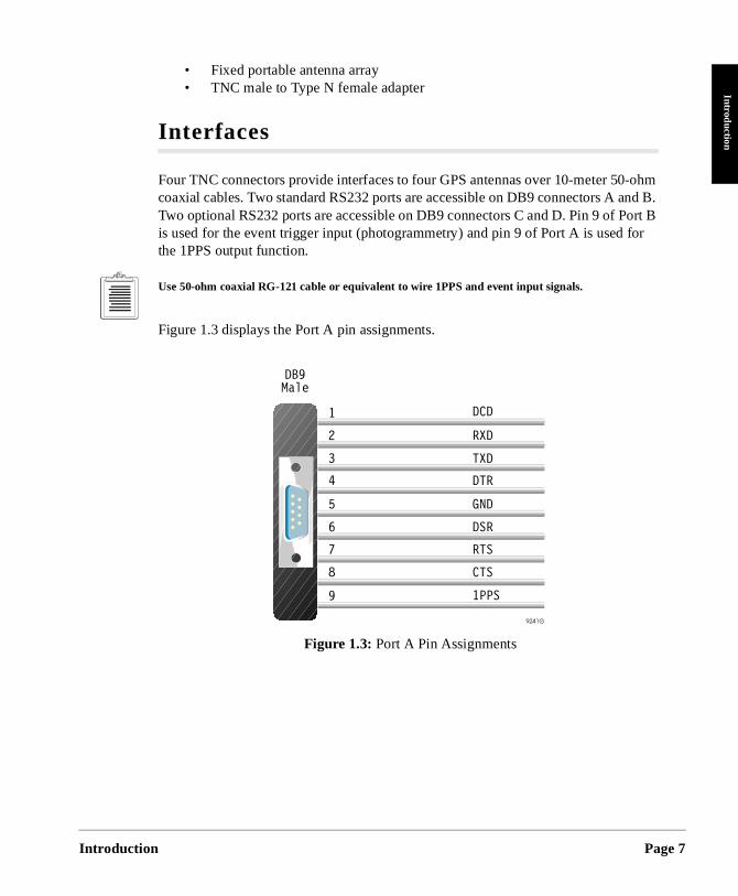
• Fixed portable antenna array• TNC male to Type N female adapter
Interfaces
Four TNC connectors provide interfaces to four GPS antennas over 10-meter 50coaxial cables. Two standard RS232 ports are accessible on DB9 connectors A and BTwo optional RS232 ports are accessible on DB9 connectors C and D. Pin 9 of Pis used for the event trigger input (photogrammetry) and pin 9 of Port A is used fthe 1PPS output function.
Use 50-ohm coaxial RG-121 cable or equivalent to wire 1PPS and event input signals.
Figure 1.3 displays the Port A pin assignments.
Figure 1.3: Port A Pin Assignments
n Page 7
Page 8
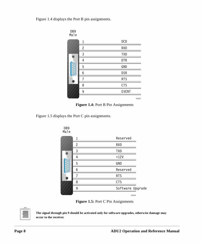
Figure 1.4 displays the Port B pin assignments.
Figure 1.5 displays the Port C pin assignments.
The signal through pin 9 should be activated only for software upgrades, otherwise damage may occur to the receiver.
Figure 1.4: Port B Pin Assignments
Figure 1.5: Port C Pin Assignments
ADU2 Operation and Reference Manual
Introductio
Introduction
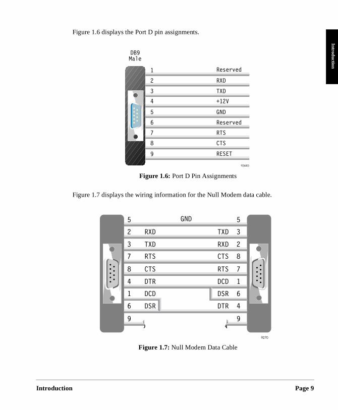
Figure 1.6 displays the Port D pin assignments.
Figure 1.7 displays the wiring information for the Null Modem data cable.
Figure 1.6: Port D Pin Assignments
Figure 1.7: Null Modem Data Cable
n Page 9
Page 10
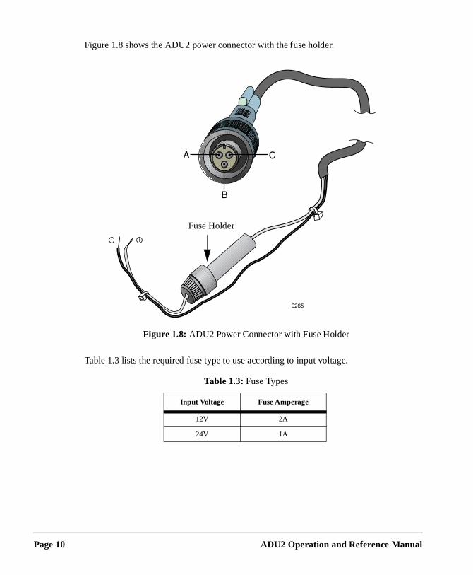
Figure 1.8 shows the ADU2 power connector with the fuse holder.
Table 1.3 lists the required fuse type to use according to input voltage.
Figure 1.8: ADU2 Power Connector with Fuse Holder
Table 1.3: Fuse Types
Input Voltage Fuse Amperage
12V 2A
24V 1A
Fuse Holder
ADU2 Operation and Reference Manual
2
QuickstartQuickstart
Quickstart
n and ons: and
nch
with
eter
ng
d
This chapter provides a brief overview for setting up the ADU2 receiver. Users experienced with the ADU2 receiver may use this chapter to accelerate the installatiooperation of the receiver. Refer to the following chapters the more detailed explanatiChapter 3 for installation procedures, Chapter 4 for antenna calibration procedures, Chapter 6 for information on troubleshooting problems.
Installation
The following procedure brings the ADU2 on-line.
1. Mount the antennas on any rigid platform as follows:
a. If using the Ashtech fixed, portable antenna array, mount it using the 1 istandard pipe fitting. Refer to Appendix A, Antennas and Cabling, for instructions to build the fixed portable antenna array.
b. If using aircraft antennas, mount the antenna on a metallic ground planeat least a 25 cm diameter.
c. If using geodetic or marine antennas, mount them on poles at least one maway from any metal surface.
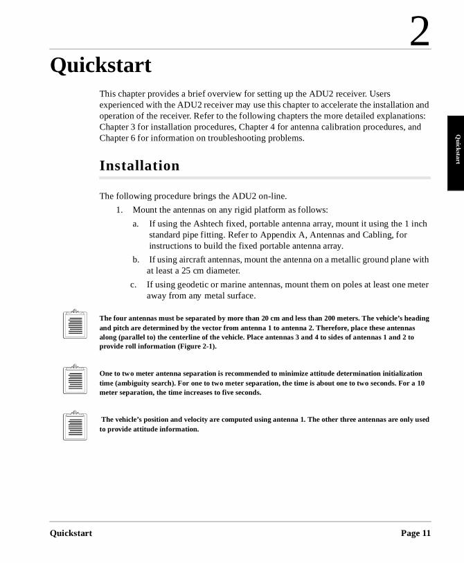
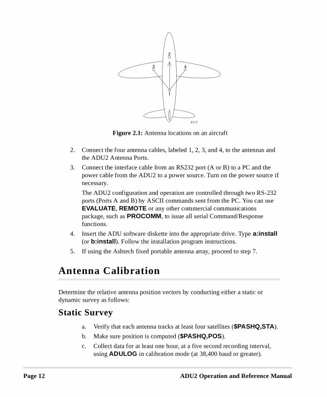
The four antennas must be separated by more than 20 cm and less than 200 meters. The vehicle’s headiand pitch are determined by the vector from antenna 1 to antenna 2. Therefore, place these antennas along (parallel to) the centerline of the vehicle. Place antennas 3 and 4 to sides of antennas 1 and 2 to provide roll information (Figure 2-1).
One to two meter antenna separation is recommended to minimize attitude determination initialization time (ambiguity search). For one to two meter separation, the time is about one to two seconds. For a 10 meter separation, the time increases to five seconds.
The vehicle’s position and velocity are computed using antenna 1. The other three antennas are only useto provide attitude information.
Page 11
Page 12
and
e e if
2 e
l,
2. Connect the four antenna cables, labeled 1, 2, 3, and 4, to the antennasthe ADU2 Antenna Ports.
3. Connect the interface cable from an RS232 port (A or B) to a PC and thpower cable from the ADU2 to a power source. Turn on the power sourcnecessary.
The ADU2 configuration and operation are controlled through two RS-23ports (Ports A and B) by ASCII commands sent from the PC. You can usEVALUATE , REMOTE or any other commercial communications package, such as PROCOMM, to issue all serial Command/Response functions.
4. Insert the ADU software diskette into the appropriate drive. Type a:install (or b:install ). Follow the installation program instructions.
5. If using the Ashtech fixed portable antenna array, proceed to step 7.
Antenna Calibration
Determine the relative antenna position vectors by conducting either a static or dynamic survey as follows:
Static Survey
a. Verify that each antenna tracks at least four satellites ($PASHQ,STA ).
b. Make sure position is computed ($PASHQ,POS).
c. Collect data for at least one hour, at a five second recording intervausing ADULOG in calibration mode (at 38,400 baud or greater).
Figure 2.1: Antenna locations on an aircraft
ADU2 Operation and Reference Manual
Quickstart
Quickstart
1
nd
nd
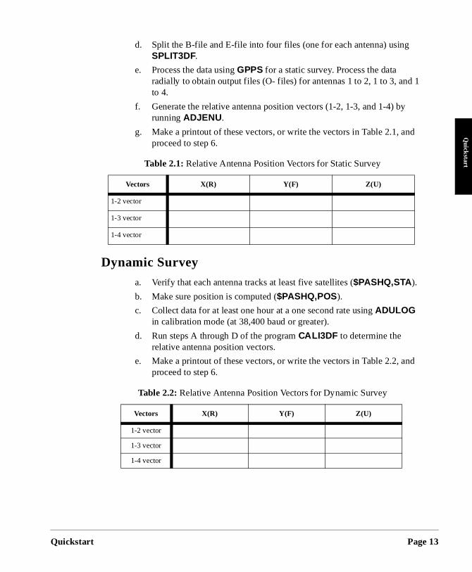
d. Split the B-file and E-file into four files (one for each antenna) usingSPLIT3DF.
e. Process the data using GPPS for a static survey. Process the data radially to obtain output files (O- files) for antennas 1 to 2, 1 to 3, andto 4.
f. Generate the relative antenna position vectors (1-2, 1-3, and 1-4) byrunning ADJENU .
g. Make a printout of these vectors, or write the vectors in Table 2.1, aproceed to step 6.
Dynamic Survey
a. Verify that each antenna tracks at least five satellites ($PASHQ,STA ).
b. Make sure position is computed ($PASHQ,POS).
c. Collect data for at least one hour at a one second rate using ADULOG in calibration mode (at 38,400 baud or greater).
d. Run steps A through D of the program CALI3DF to determine the relative antenna position vectors.
e. Make a printout of these vectors, or write the vectors in Table 2.2, aproceed to step 6.
Table 2.1: Relative Antenna Position Vectors for Static Survey
Vectors X(R) Y(F) Z(U)
1-2 vector
1-3 vector
1-4 vector
Table 2.2: Relative Antenna Position Vectors for Dynamic Survey
Vectors X(R) Y(F) Z(U)
1-2 vector
1-3 vector
1-4 vector
Page 13
Page 14
:
ion.
, you
2
, you
Enter Offset Vector Information
6. Enter the position vectors into the receiver with the following commands
$PASHS,3DF,V12,Sddd.ddd,Sddd.ddd,Sddd.ddd $PASHS,3DF,V13,Sddd.ddd,Sddd.ddd,Sddd.ddd $PASHS,3DF,V14,Sddd.ddd,Sddd.ddd,Sddd.ddd
where ddd.ddd is a vector component and S is the sign of the vector component. Be sure to include the sign (+/-) of the vector value.
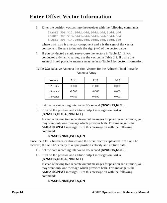
7. If you conducted a static survey, use the vectors in Table 2.1. If you conducted a dynamic survey, use the vectors in Table 2.2. If using the Ashtech fixed portable antenna array, refer to Table 3 for vector informat
8. Set the data recording interval to 0.5 second ($PASHS,RCI,0).
9. Turn on the position and attitude output messages on Port A ($PASHS,OUT,A,PBN,ATT ).
Instead of having two separate output messages for position and attitudemay want only one message which provides both. This message is the NMEA $GPPAT message. Turn this message on with the following command:
$PASHS,NME,PAT,A,ON
Once the ADU2 has been calibrated and the offset vectors uploaded to the ADUreceiver, the ADU2 is ready to output position velocity and attitude data.
10. Set the data recording interval to 0.5 second ($PASHS,RCI,0).
11. Turn on the position and attitude output messages on Port A ($PASHS,OUT,A,PBN,ATT ).
Instead of having two separate output messages for position and attitudemay want only one message which provides both. This message is the NMEA $GPPAT message. Turn this message on with the following command:
$PASHS,NME,PAT,A,ON
Table 2.3: Relative Antenna Position Vectors for the Ashtech Fixed Portable Antenna Array
Vectors X(R) Y(F) Z(U)
1-2 vector 0.000 +1.000 0.000
1-3 vector -0.500 +0.500 0.000
1-4 vector +0.500 +0.500 0.000
ADU2 Operation and Reference Manual
Quickstart
Quickstart
d
Inspect the NMEA and Raw Data, found in Chapter 5, Command Response Formats, output formats closely to determine which output messages are most applicable for your application.
$GPPAT is not a standard NMEA message. If only heading information is required, the NMEA standard message $GPHDT should be used.
Graphical displays of heading, pitch, roll, position, course over ground, and speeover ground are available in the ADULOG program (DOS) and in the EVALUATE program (Windows).
Page 15

Page 16
ADU2 Operation and Reference Manual
3
InstallationInstallation
Installation
of
em
The ADU2 installation procedure consists of the following parts:
• Antennas• Equipment• Software
Antenna Installation
Several different types of antennas and configurations are available to meet a varietymounting requirements. Mount the four antennas on the vehicle using the hardware furnished or locally fabricated hardware. Refer to Appendix A, Antennas and Cabling, for a detailed description on the various types of GPS antennas and how to install thproperly on a vehicle to avoid high multipath and skyward obstruction.
All four antennas must be connected in order for the attitude computations to take place.
For best results the antenna array or platform must be completely rigid.
Table 3.1 provides information to keep in mind when choosing antenna locations.
Table 3.1: Antenna Placement Suggestions
Antenna Consideration Suggestion
Antenna location and spacing • Avoid placing antennas on wing tips of aircraft. Due to excessive wing-flex of the antenna baseline, the attitude computation algorithm becomes unreliable.
• The software in the ADU2 requires that the antennas be separated from each other by at least 20 centimeters. The further the antennas are spaced from each other, the greater the potential attitude measurement accuracy provided by the ADU2. Refer
to Appendix B, Performance Improvement, for more information.
Page 17
Page 18
Accuracy Accuracy is directly proportional to the antenna separation. Typical attitude accuracies versus antenna separation are described in Appendix C. Also refer to the references [2,3] in Appendix D. Pitch and roll accuracies are typically a factor of two worse than the heading accuracy when a square antenna array is used.
Multipath Migration The reliability of the phase ambiguity resolution and the attitude accuracy is degraded by multipath signals. The antennas should be located on top of the vehicle (or platform) to minimize the possibility of satellite signals reflecting off metal objects near the antenna.
Stability The ADU2 behavior depends upon the stability of the four-antenna system. This means that the selected antenna mounting locations should not move in any direction (up/down, left/right) relative to the other antennas. If the vehicle (or platform) moves, the entire antenna system should move in the same manner. Use care in mounting antennas on flexible structures such as the mast of a ship or the wing tips of an airplane.
Maximum Length The supplied cables have a maximum length for the particular type of cable. Do not extend the cables beyond 30 meters without an in-line amplifier, provided as an option, since the radio frequency (RF) signal presented to the ADU2 will be degraded.
Geometrical Configuration • Almost any geometric shape is acceptable provided that none of the resultant vectors are co-linear (i.e. if three antennas are arranged in a line, Antenna 1 may not be one of those antennas (Figure 3.1).
• Antennas do not need to be co-planar, however, for best results, at least two antennas should be at the same height.
Table 3.1: Antenna Placement Suggestions (continued)
Antenna Consideration Suggestion
ADU2 Operation and Reference Manual
Installation
Installation
e line
e of
nd 2
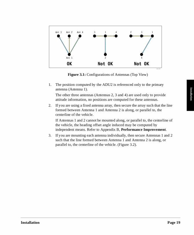
1. The position computed by the ADU2 is referenced only to the primary antenna (Antenna 1).
The other three antennas (Antennas 2, 3 and 4) are used only to provideattitude information, no positions are computed for these antennas.
2. If you are using a fixed antenna array, then secure the array such that thformed between Antenna 1 and Antenna 2 is along, or parallel to, the centerline of the vehicle.
If Antennas 1 and 2 cannot be mounted along, or parallel to, the centerlinthe vehicle, the heading offset angle induced may be computed by independent means. Refer to Appendix B, Performance Improvement.
3. If you are mounting each antenna individually, then secure Antennas 1 asuch that the line formed between Antenna 1 and Antenna 2 is along, orparallel to, the centerline of the vehicle. (Figure 3.2).
Figure 3.1: Configurations of Antennas (Top View)
Page 19
Page 20
e of
s of
ctor
e
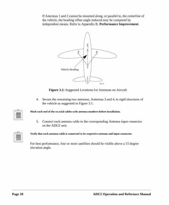
If Antennas 1 and 2 cannot be mounted along, or parallel to, the centerlinthe vehicle, the heading offset angle induced may be computed by independent means. Refer to Appendix B, Performance Improvement.
4. Secure the remaining two antennas, Antennas 3 and 4, to rigid structurethe vehicle as suggested in Figure 3.1.
Mark each end of the co-axial cables with antenna numbers before installation.
5. Connect each antenna cable to the corresponding Antenna input conneon the ADU2 unit.
Verify that each antenna cable is connected to its respective antenna and input connector.
For best performance, four or more satellites should be visible above a 15 degreelevation angle.
Figure 3.2: Suggested Locations for Antennas on Aircraft
Vehicle Heading
ADU2 Operation and Reference Manual
Installation
Installation
The PC
is
will
Software Installation
The ADU2 package contains software diskettes for the initial antenna calibration.software is installed on a personal computer. The minimum requirements for theare:
• 486 processor• Math co-processor
• EGA video display
• Three megabytes of hard disk space
• Microsoft Windows if using the EVALUATE software
To install the software programs:
1. Insert ADU software diskette 1 into the appropriate drive. If drive A, typea:install or if drive B, type b:install . Then press <ENTER>.
After a few moments the following message appears: This program installs Ashtech’s ADU2 Software Version X.X.XX on your computer system and verifies the integrity of the
distribution files. Press the [Esc] key at any time to abort the installation.
Press [Esc] to quit, any other key to continue...
2. Press any key. A prompt similar to the following appears: Detected Computer ConfigurationDOS Version 6.22 CPU type is an 80486 Math coprocessor detectedVGA Video Adapter Card Press [Esc] to quit, any other key to continue...
3. Press any key. The program prompts:On which disk drive to you wish to install ADU:Drive C:Drive D:
4. Make a selection based upon your computer configuration. The default Drive C. Select a drive letter and press <ENTER>.
5. The program prompts for the name of a subdirectory where the softwarebe installed. The default designation ADU, but you can specify another subdirectory. To accept the default, press <ENTER>. To specify another name, type \ followed by the subdirectory name, and press <ENTER>.
6. The program displays “Installing ADU2—Please wait. ” A a list of files appears on the screen. After a few minutes, the program prompts:
May I create/mo dify your AUTOEXEC.BAT fil e if needed?
Page 21
Page 22
n
7. Unless you have a specific reason not to modify autoexec.bat, type Y. The program prompts: The node “C:\ADU” has been added to the existing PATH command.
The GPPS program and its associated files must be in the DOS path statement.
8. Press any key. The program prompts: May I modify your CONFIG.SYS file if needed (Y/N)?
9. Unless you have a specific reason not to modify your config.sys file, type Y.
Install modifies the config.sys file if necessary, then displays the following prompt:Press any key.
10. Press any key. The screen goes blank for a moment, then the program prompts:The ADU software installation has concluded successfully.
Press any key to continue...
11. Press any key. The program displays the DOS prompt: \ADU>
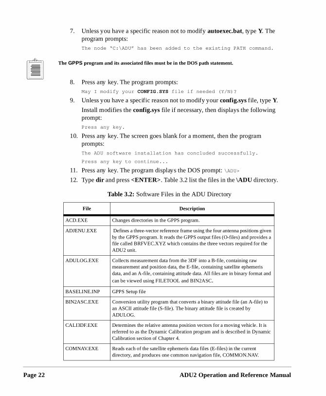
12. Type dir and press <ENTER>. Table 3.2 list the files in the \ADU directory.
Table 3.2: Software Files in the ADU Directory
File Description
ACD.EXE Changes directories in the GPPS program.
ADJENU.EXE Defines a three-vector reference frame using the four antenna positions giveby the GPPS program. It reads the GPPS output files (O-files) and provides afile called BRFVEC.XYZ which contains the three vectors required for the ADU2 unit.
ADULOG.EXE Collects measurement data from the 3DF into a B-file, containing raw measurement and position data, the E-file, containing satellite ephemeris data, and an A-file, containing attitude data. All files are in binary format and
can be viewed using FILETOOL and BIN2ASC.
BASELINE.INP GPPS Setup file
BIN2ASC.EXE Conversion utility program that converts a binary attitude file (an A-file) to an ASCII attitude file (S-file). The binary attitude file is created by ADULOG.
CALI3DF.EXE Determines the relative antenna position vectors for a moving vehicle. It is referred to as the Dynamic Calibration program and is described in DynamicCalibration section of Chapter 4.
COMNAV.EXE Reads each of the satellite ephemeris data files (E-files) in the current directory, and produces one common navigation file, COMMON.NAV.
ADU2 Operation and Reference Manual
Installation
Installation
.
13. Start Microsoft Windows.
14. Insert the EVALUATE software diskette into the appropriate drive.
15. Select Run from the File Menu.
16. Enter the following command in the Command Line of the Run dialog box:
a:\setup (or b:\setup if the diskette is in drive B).
17. Click the OK button to start the EVALUATE setup program.
18. Follow the setup program instructions.
19. Refer to the EVALUATE User’s Guide for additional information on EVALUATE .
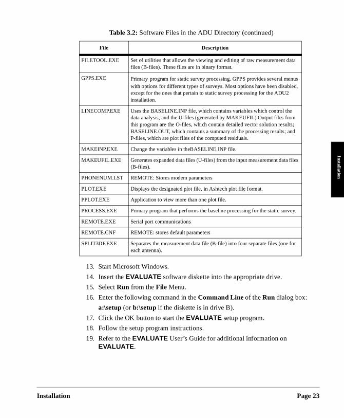
FILETOOL.EXE Set of utilities that allows the viewing and editing of raw measurement data files (B-files). These files are in binary format.
GPPS.EXE Primary program for static survey processing. GPPS provides several menuswith options for different types of surveys. Most options have been disabled,except for the ones that pertain to static survey processing for the ADU2 installation.
LINECOMP.EXE Uses the BASELINE.INP file, which contains variables which control the data analysis, and the U-files (generated by MAKEUFIL) Output files from this program are the O-files, which contain detailed vector solution results; BASELINE.OUT, which contains a summary of the processing results; and P-files, which are plot files of the computed residuals.
MAKEINP.EXE Change the variables in theBASELINE.INP file.
MAKEUFIL.EXE Generates expanded data files (U-files) from the input measurement data files (B-files).
PHONENUM.LST REMOTE: Stores modem parameters
PLOT.EXE Displays the designated plot file, in Ashtech plot file format.
PPLOT.EXE Application to view more than one plot file.
PROCESS.EXE Primary program that performs the baseline processing for the static survey
REMOTE.EXE Serial port communications
REMOTE.CNF REMOTE: stores default parameters
SPLIT3DF.EXE Separates the measurement data file (B-file) into four separate files (one foreach antenna).
Table 3.2: Software Files in the ADU Directory (continued)
File Description
Page 23
Page 24
e
e
Equipment Installation
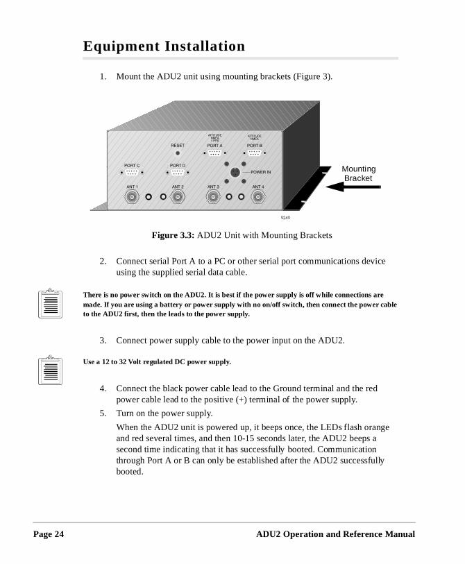
1. Mount the ADU2 unit using mounting brackets (Figure 3).
2. Connect serial Port A to a PC or other serial port communications devicusing the supplied serial data cable.
There is no power switch on the ADU2. It is best if the power supply is off while connections are made. If you are using a battery or power supply with no on/off switch, then connect the power cable to the ADU2 first, then the leads to the power supply.
3. Connect power supply cable to the power input on the ADU2.
Use a 12 to 32 Volt regulated DC power supply.
4. Connect the black power cable lead to the Ground terminal and the red power cable lead to the positive (+) terminal of the power supply.
5. Turn on the power supply.
When the ADU2 unit is powered up, it beeps once, the LEDs flash orangand red several times, and then 10-15 seconds later, the ADU2 beeps asecond time indicating that it has successfully booted. Communication through Port A or B can only be established after the ADU2 successfullybooted.
Figure 3.3: ADU2 Unit with Mounting Brackets
Mounting Bracket
ADU2 Operation and Reference Manual
Installation
Installation
U2
ss
els tes.
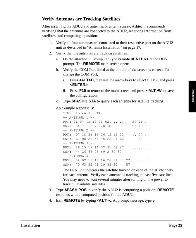
Verify Antennas are Tracking Satellites
After installing the ADU2 and antennas or antenna array, Ashtech recommends verifying that the antennas are connected to the ADU2, receiving information from satellites, and computing a position.
1. Verify all four antennas are connected to their respective port on the ADunit as described in “Antenna Installation” on page 17.
2. Verify that the antennas are tracking satellites.
a. On the attached PC computer, type remote <ENTER> at the DOS prompt. The REMOTE main screen opens.
b. Verify the COM Port listed at the bottom of the screen is correct. To change the COM Port:
i. Press <ALT>C , then use the arrow keys to select COM2, and pre<ENTER>.
ii. Press F10 to return to the main screen and press <ALT>W to save the configuration.
c. Type $PASHQ,STA to query each antenna for satellite tracking.
An example response is:TIME: 15:46:36 UTA-- ANTENNA 1 --PRN: 26 07 15 19 31 02. .. .. .. 27 16 ..SNR: 34 71 15 72 28 68 55 19-- ANTENNA 2 --PRN: 07 18 31 19 26 15 16 02 .. .. 27 ..SNR: 62 08 24 56 35 22 21 62 37-- ANTENNA 3 --PRN: 26 15 19 16 07 31 02 27 .. .. .. .. SNR: 44 26 68 26 69 2 64 52-- ANTENNA 4 --PRN: 02 07 15 19 16 26 31 .. 27 .. .. ..SNR: 70 63 32 71 29 33 20 57
The PRN line indicates the satellite tracked on each of the 16 channfor each antenna. Verify each antenna is tracking at least five satelliYou may need to wait several minutes after turning on the power to track all available satellites.
3. Type $PASH,POS to verify the ADU2 is computing a position. REMOTE responds with a computed position for the ADU2.
4. Exit REMOTE by typing <ALT>x . At prompt message, type y.
Page 25

Page 26
ADU2 Operation and Reference Manual
4
Antenna CalibrationCalibration
Antenna C
tors
nna
ves
This chapter describes the antenna calibration process for a static calibration and a dynamic calibration. An antenna calibration must be performed and the resultant vecentered before the ADU2 can calculate attitudes.
A static calibration can be used for the following circumstances:
• stationary vehicle• vessel moored to a pier or in dry dock. A static calibration tolerates small ante
motions such as rising and falling tides if the tide range is less than 6 feet.• aircraft parked on tarmac
A dynamic calibration should be used for a vessel, aircraft, or other vehicle which moduring the antenna calibration.
Static Calibration Procedure
Conduct the static calibration procedure when the vehicle does not physically move during calibration. You only need to calibrate the antennas once. However, you mustrecalibrate the antenna array if the relative positions of the antennas change (i.e. replacing an antenna, lowering and /or raising of antennas, etc.).
Every attempt should be made to set the antenna platform level during calibration.
The static calibration procedure has the following steps:
1. Collect the data (ADULOG )
2. Split the data (SPLIT3DF)
3. Process and view the data (GPPS)
4. Adjust relative antenna positions (ADJENU )
5. Enter offset vector information (REMOTE).
Collect the Data
After the antennas are tracking satellites, the calibration data can be collected. Use ADULOG to collect measurement data. Additional, detailed information about ADULOG and the measurement data is available in Chapter 7, ADULOG. Table 4.1
alibration Page 27
Page 28
ata
the
n
to
ant
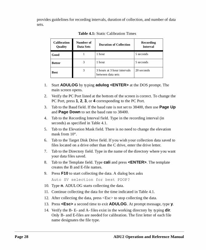
provides guidelines for recording intervals, duration of collection, and number of dsets.
1. Start ADULOG by typing adulog <ENTER> at the DOS prompt. The main screen opens.
2. Verify the PC Port listed at the bottom of the screen is correct. To changePC Port, press 1, 2, 3, or 4 corresponding to the PC Port.
3. Tab to the Baud field. If the baud rate is not set to 38400, then use Page Up and Page Down to set the baud rate to 38400.
4. Tab to the Recording Interval field. Type in the recording interval (in seconds) as specified in Table 4.1.
5. Tab to the Elevation Mask field. There is no need to change the elevatiomask from 10°.
6. Tab to the Target Disk Drive field. If you wish your collection data savedfiles located on a drive other than the C drive, enter the drive letter.
7. Tab to the Directory field. Type in the name of the directory where you wyour data files saved.
8. Tab to the Template field. Type cali and press <ENTER>. The template creates the B and E-file names.
9. Press F10 to start collecting the data. A dialog box asks
Auto SV selection for best PDOP?
10. Type n. ADULOG starts collecting the data.
11. Continue collecting the data for the time indicated in Table 4.1.
12. After collecting the data, press <Esc> to stop collecting the data.
13. Press <Esc> a second time to exit ADULOG . At prompt message, type y.
14. Verify the B- E- and A- files exist in the working directory by typing dir . Only B- and E-files are needed for calibration. The first letter of each filename designates the file type.
Table 4.1: Static Calibration Times
Calibration Quality
Number ofData Sets
Duration of CollectionRecordingInterval
Good 1 1 hour 5 seconds
Better 3 1 hour 5 seconds
Best3 3 hours at 3 hour intervals
between data sets20 seconds
ADU2 Operation and Reference Manual
Antenna C
Calibration
t be
B-
ss
o
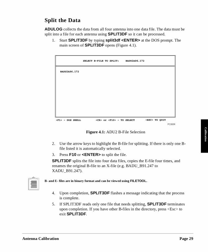
Split the Data
ADULOG collects the data from all four antenna into one data file. The data mussplit into a file for each antenna using SPLIT3DF so it can be processed.
1. Start SPLIT3DF by typing split3df <ENTER> at the DOS prompt. The main screen of SPLIT3DF opens (Figure 4.1).
2. Use the arrow keys to highlight the B-file for splitting. If there is only one file listed it is automatically selected.
3. Press F10 or <ENTER> to split the file.
SPLIT3DF splits the file into four data files, copies the E-file four times, and renames the original B-file to an X-file (e.g. BADU_B91.247 to XADU_B91.247).
B- and E- files are in binary format and can be viewed using FILETOOL .
4. Upon completion, SPLIT3DF flashes a message indicating that the proceis complete.
5. If SPLIT3DF reads only one file that needs splitting, SPLIT3DF terminates upon completion. If you have other B-files in the directory, press <Esc> texit SPLIT3DF.
Figure 4.1: ADU2 B-File Selection
alibration Page 29
Page 30
g
y
s to
the n
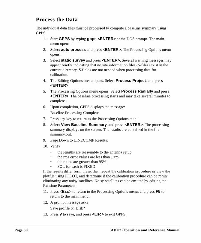
Process the Data
The individual data files must be processed to compute a baseline summary usinGPPS.
1. Start GPPS by typing gpps <ENTER> at the DOS prompt. The main menu opens.
2. Select auto process and press <ENTER>. The Processing Options menuopens.
3. Select static survey and press <ENTER>. Several warning messages maappear briefly indicating that no site information files (S-files) exist in thecurrent directory. S-fields are not needed when processing data for calibration.
4. The Editing Options menu opens. Select Process Project , and press <ENTER>.
5. The Processing Options menu opens. Select Process Radially and press <ENTER>. The baseline processing starts and may take several minutecomplete.
6. Upon completion, GPPS displays the message:
Baseline Processing Complete
7. Press any key to return to the Processing Options menu.
8. Select View Baseline Summary , and press <ENTER>. The processing summary displays on the screen. The results are contained in the file summary.out.
9. Page Down to LINECOMP Results.
10. Verify
• the lengths are reasonable to the antenna setup• the rms error values are less than 1 cm• the ratios are greater than 95%• SOL for each is FIXED
If the results differ form these, then repeat the calibration procedure or view plotfile using PPLOT, and determine if the calibration procedure can be rerueliminating any noisy satellites. Noisy satellites can be omitted by editing theRuntime Parameters.
11. Press <Esc> to return to the Processing Options menu, and press F5 to return to the main menu.
12. A prompt message asks
Save profile on Disk?
13. Press y to save, and press <Esc> to exit GPPS.
ADU2 Operation and Reference Manual
Antenna C
Calibration
need
type ed
the ight. ee
sed you tenna
the
Adjust relative antenna positions
After processing and viewing the baseline results, the relative antenna positionsto be calculated using ADJENU (ADJENU stands for adjust east north up). ADJENU reads the output files (O-files) generated by GPPS and computes the relative antenna position vectors.
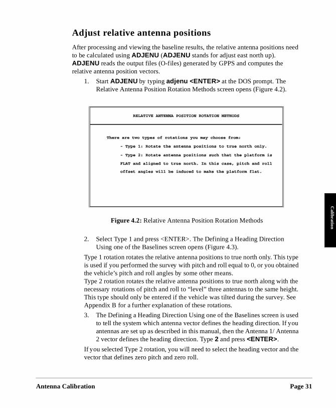
1. Start ADJENU by typing adjenu <ENTER> at the DOS prompt. The Relative Antenna Position Rotation Methods screen opens (Figure 4.2).
2. Select Type 1 and press <ENTER>. The Defining a Heading Direction Using one of the Baselines screen opens (Figure 4.3).
Type 1 rotation rotates the relative antenna positions to true north only. This is used if you performed the survey with pitch and roll equal to 0, or you obtainthe vehicle’s pitch and roll angles by some other means. Type 2 rotation rotates the relative antenna positions to true north along withnecessary rotations of pitch and roll to “level” three antennas to the same heThis type should only be entered if the vehicle was tilted during the survey. SAppendix B for a further explanation of these rotations.
3. The Defining a Heading Direction Using one of the Baselines screen is uto tell the system which antenna vector defines the heading direction. If antennas are set up as described in this manual, then the Antenna 1/ An2 vector defines the heading direction. Type 2 and press <ENTER>.
If you selected Type 2 rotation, you will need to select the heading vector andvector that defines zero pitch and zero roll.
Figure 4.2: Relative Antenna Position Rotation Methods
alibration Page 31
Page 32
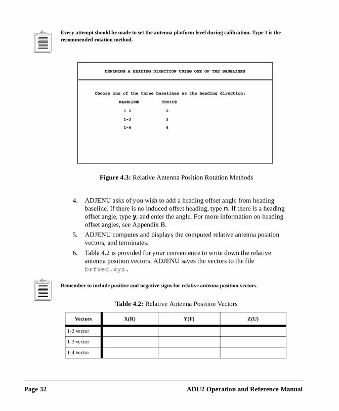
Every attempt should be made to set the antenna platform level during calibration. Type 1 is the recommended rotation method.
4. ADJENU asks of you wish to add a heading offset angle from heading baseline. If there is no induced offset heading, type n. If there is a heading offset angle, type y, and enter the angle. For more information on headingoffset angles, see Appendix B.
5. ADJENU computes and displays the computed relative antenna positionvectors, and terminates.
6. Table 4.2 is provided for your convenience to write down the relative antenna position vectors. ADJENU saves the vectors to the file brfvec.xyz.
Remember to include positive and negative signs for relative antenna position vectors.
Figure 4.3: Relative Antenna Position Rotation Methods
Table 4.2: Relative Antenna Position Vectors
Vectors X(R) Y(F) Z(U)
1-2 vector
1-3 vector
1-4 vector
ADU2 Operation and Reference Manual
Antenna C
Calibration
as 1 ore
as 1 ore
as 1 ore
ng
tem. If
the nges
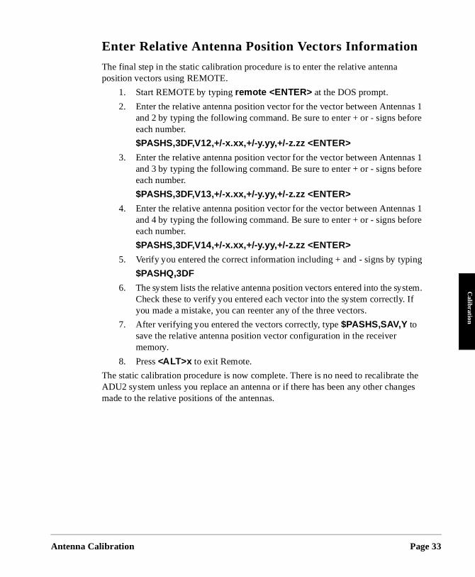
Enter Relative Antenna Position Vectors Information
The final step in the static calibration procedure is to enter the relative antenna position vectors using REMOTE.
1. Start REMOTE by typing remote <ENTER> at the DOS prompt.
2. Enter the relative antenna position vector for the vector between Antennand 2 by typing the following command. Be sure to enter + or - signs befeach number.
$PASHS,3DF,V12,+/-x.xx,+/-y.yy,+/-z.zz <ENTER>
3. Enter the relative antenna position vector for the vector between Antennand 3 by typing the following command. Be sure to enter + or - signs befeach number.
$PASHS,3DF,V13,+/-x.xx,+/-y.yy,+/-z.zz <ENTER>
4. Enter the relative antenna position vector for the vector between Antennand 4 by typing the following command. Be sure to enter + or - signs befeach number.
$PASHS,3DF,V14,+/-x.xx,+/-y.yy,+/-z.zz <ENTER>
5. Verify you entered the correct information including + and - signs by typi
$PASHQ,3DF
6. The system lists the relative antenna position vectors entered into the sysCheck these to verify you entered each vector into the system correctly.you made a mistake, you can reenter any of the three vectors.
7. After verifying you entered the vectors correctly, type $PASHS,SAV,Y to save the relative antenna position vector configuration in the receiver memory.
8. Press <ALT>x to exit Remote.
The static calibration procedure is now complete. There is no need to recalibrateADU2 system unless you replace an antenna or if there has been any other chamade to the relative positions of the antennas.
alibration Page 33
Page 34
ines ents.
for e data
the
n
to
ant
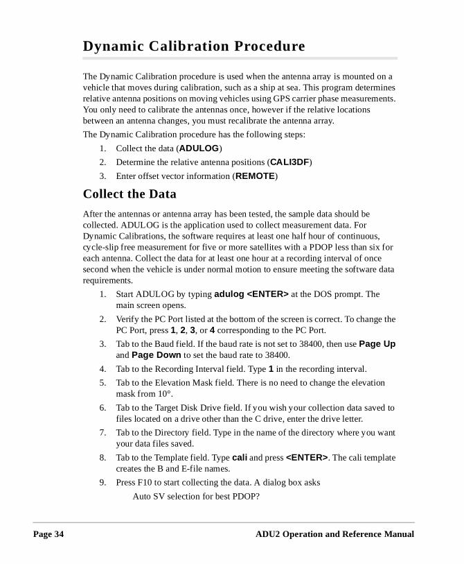
Dynamic Calibration Procedure
The Dynamic Calibration procedure is used when the antenna array is mounted on a vehicle that moves during calibration, such as a ship at sea. This program determrelative antenna positions on moving vehicles using GPS carrier phase measuremYou only need to calibrate the antennas once, however if the relative locations between an antenna changes, you must recalibrate the antenna array.
The Dynamic Calibration procedure has the following steps:
1. Collect the data (ADULOG )
2. Determine the relative antenna positions (CALI3DF )
3. Enter offset vector information (REMOTE)
Collect the Data
After the antennas or antenna array has been tested, the sample data should becollected. ADULOG is the application used to collect measurement data. For Dynamic Calibrations, the software requires at least one half hour of continuous,cycle-slip free measurement for five or more satellites with a PDOP less than sixeach antenna. Collect the data for at least one hour at a recording interval of oncsecond when the vehicle is under normal motion to ensure meeting the softwarerequirements.
1. Start ADULOG by typing adulog <ENTER> at the DOS prompt. The main screen opens.
2. Verify the PC Port listed at the bottom of the screen is correct. To changePC Port, press 1, 2, 3, or 4 corresponding to the PC Port.
3. Tab to the Baud field. If the baud rate is not set to 38400, then use Page Up and Page Down to set the baud rate to 38400.
4. Tab to the Recording Interval field. Type 1 in the recording interval.
5. Tab to the Elevation Mask field. There is no need to change the elevatiomask from 10°.
6. Tab to the Target Disk Drive field. If you wish your collection data savedfiles located on a drive other than the C drive, enter the drive letter.
7. Tab to the Directory field. Type in the name of the directory where you wyour data files saved.
8. Tab to the Template field. Type cali and press <ENTER>. The cali template creates the B and E-file names.
9. Press F10 to start collecting the data. A dialog box asks
Auto SV selection for best PDOP?
ADU2 Operation and Reference Manual
Antenna C
Calibration
ction
s not
s
mic
10. Type n to enter calibration mode, and ADULOG starts collecting the data.
11. Continue collecting the data for at 1east one hour. This ensures the colleof 30 minutes of cycle-slip free measurements.
12. After collecting the data, press <Esc> to stop collecting the data.
13. Press <Esc> a second time to exit ADULOG . At prompt message, type y.
14. Verify the B- E- and A- files exist in the working directory by typing dir . Only B- and E-files are needed for calibration. The first letter of each filename designates the file type.
Determine Relative Antenna Positions
After the data has been collected the relative vectors need to be computed. CALI3DF computes highly accurate relative position vectors for the four antennas and doerequire the vehicle to be stationary. It achieves this by employing double differencing techniques, a Kalman filter, and an ambiguity search method. Refer to reference[1,2] listed in Appendix C for an explanation of double differencing and phase ambiguity resolution. Reference [3] provides a theoretical description of the DynaCalibration.
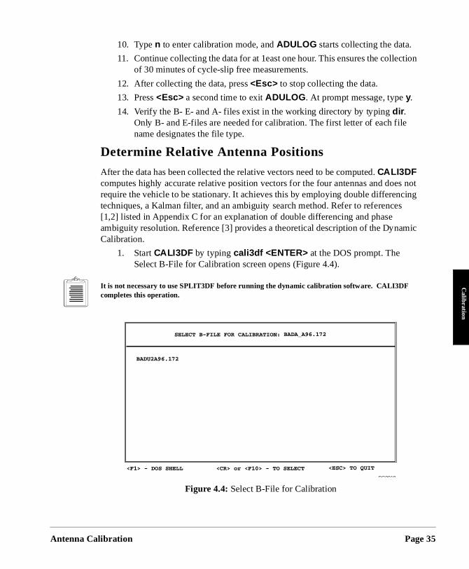
1. Start CALI3DF by typing cali3df <ENTER> at the DOS prompt. The Select B-File for Calibration screen opens (Figure 4.4).
It is not necessary to use SPLIT3DF before running the dynamic calibration software. CALI3DF completes this operation.
Figure 4.4: Select B-File for Calibration
alibration Page 35
Page 36
ne
e tive
sed ition can ning
me as d in
2. Use the arrow keys to highlight the B-file for calibration. If there is only oB-file listed it is automatically selected.
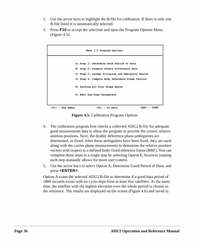
3. Press F10 to accept the selection and open the Program Options Menu (Figure 4.5).
4. The calibration program first checks a collected ADU2 B-file for adequatgood measurement data to allow the program to provide the correct relaantenna positions. Next, the double difference phase ambiguities are determined, or fixed. After these ambiguities have been fixed, they are ualong with the carrier phase measurements to determine the relative posvectors with respect to a defined body-fixed reference frame (BRF). You complete these steps in a single step by selecting Option E, however runeach step manually allows for more user control.
5. Use the arrow keys to select Option A, Determine Good Period of Data, and press <ENTER>.
Option A scans the selected ADU2 B-file to determine if a good data period of 1800 seconds exists with no cycle-slips from at least five satellites. At the satime, the satellite with the highest elevation over the whole period is chosen the reference. The results are displayed on the screen (Figure 4.6) and save
Figure 4.5: Calibration Program Options
ADU2 Operation and Reference Manual
Antenna C
Calibration
ich els, h a
(Fig-
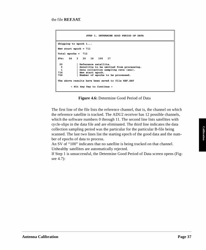
the file REF.SAT.
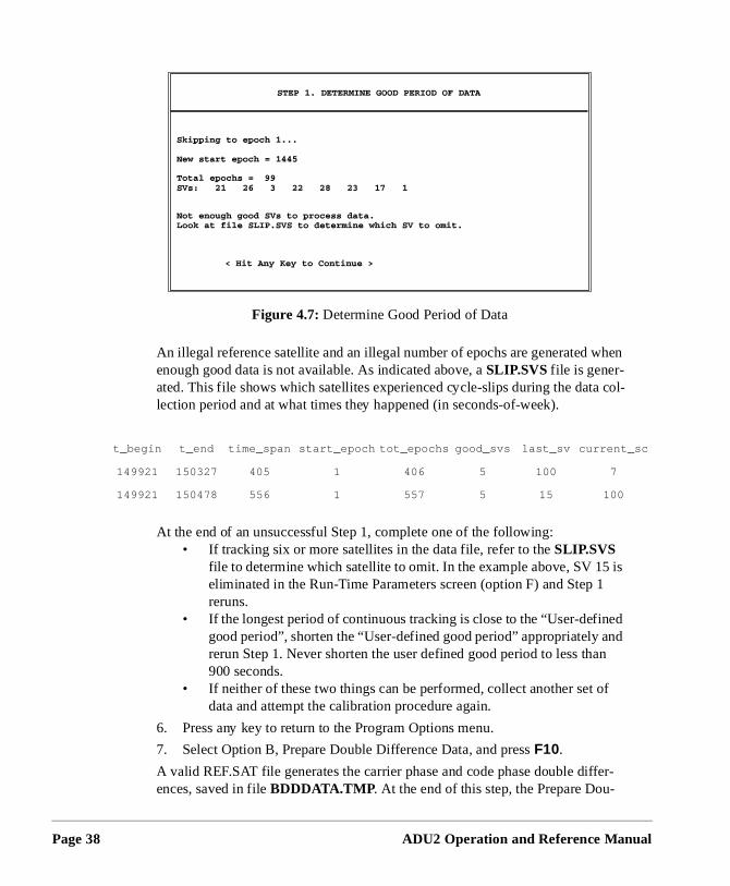
The first line of the file lists the reference channel, that is, the channel on whthe reference satellite is tracked. The ADU2 receiver has 12 possible channwhich the software numbers 0 through 11. The second line lists satellites witcycle-slips in the data file and are eliminated. The third line indicates the datcollection sampling period was the particular for the particular B-file being scanned. The last two lines list the starting epoch of the good data and the num-ber of epochs of data to process.An SV of “100” indicates that no satellite is being tracked on that channel. Unhealthy satellites are automatically rejected.If Step 1 is unsuccessful, the Determine Good Period of Data screen opens ure 4.7):
Figure 4.6: Determine Good Period of Data
alibration Page 37
Page 38
hen
col-
is
ed nd n
f
er-
t_
1
1
An illegal reference satellite and an illegal number of epochs are generated wenough good data is not available. As indicated above, a SLIP.SVS file is gener-ated. This file shows which satellites experienced cycle-slips during the datalection period and at what times they happened (in seconds-of-week).
At the end of an unsuccessful Step 1, complete one of the following: • If tracking six or more satellites in the data file, refer to the SLIP.SVS
file to determine which satellite to omit. In the example above, SV 15eliminated in the Run-Time Parameters screen (option F) and Step 1reruns.
• If the longest period of continuous tracking is close to the “User-defingood period”, shorten the “User-defined good period” appropriately arerun Step 1. Never shorten the user defined good period to less tha900 seconds.
• If neither of these two things can be performed, collect another set odata and attempt the calibration procedure again.
6. Press any key to return to the Program Options menu.
7. Select Option B, Prepare Double Difference Data, and press F10.
A valid REF.SAT file generates the carrier phase and code phase double diffences, saved in file BDDDATA.TMP . At the end of this step, the Prepare Dou-
Figure 4.7: Determine Good Period of Data
begin t_end time_span start_epoch tot_epochs good_svs last_sv current_sc
49921 150327 405 1 406 5 100 7
49921 150478 556 1 557 5 15 100
ADU2 Operation and Reference Manual
Antenna C
Calibration
bigu-
sing
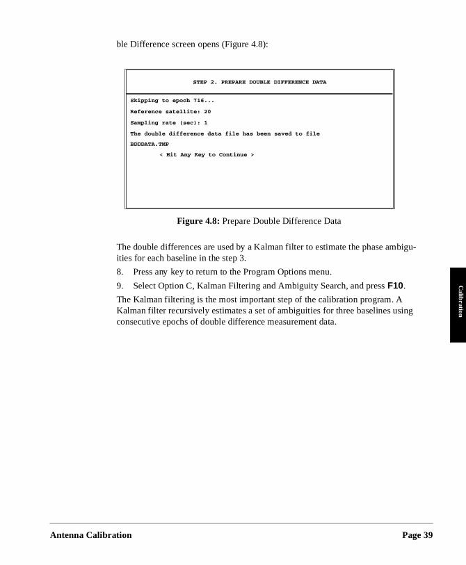
ble Difference screen opens (Figure 4.8):
The double differences are used by a Kalman filter to estimate the phase amities for each baseline in the step 3.
8. Press any key to return to the Program Options menu.
9. Select Option C, Kalman Filtering and Ambiguity Search, and press F10.
The Kalman filtering is the most important step of the calibration program. AKalman filter recursively estimates a set of ambiguities for three baselines uconsecutive epochs of double difference measurement data.
Figure 4.8: Prepare Double Difference Data
alibration Page 39
Page 40
very
lter’s um-
gion) re 0 on l-
tors ates.
(but fsets
d
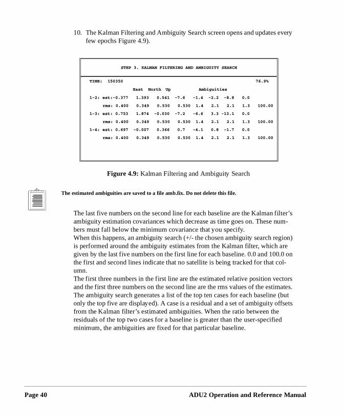
10. The Kalman Filtering and Ambiguity Search screen opens and updates efew epochs Figure 4.9).
The estimated ambiguities are saved to a file amb.fix. Do not delete this file.
The last five numbers on the second line for each baseline are the Kalman fiambiguity estimation covariances which decrease as time goes on. These nbers must fall below the minimum covariance that you specify. When this happens, an ambiguity search (+/- the chosen ambiguity search reis performed around the ambiguity estimates from the Kalman filter, which agiven by the last five numbers on the first line for each baseline. 0.0 and 100.the first and second lines indicate that no satellite is being tracked for that coumn. The first three numbers in the first line are the estimated relative position vecand the first three numbers on the second line are the rms values of the estimThe ambiguity search generates a list of the top ten cases for each baselineonly the top five are displayed). A case is a residual and a set of ambiguity offrom the Kalman filter’s estimated ambiguities. When the ratio between the residuals of the top two cases for a baseline is greater than the user-specifieminimum, the ambiguities are fixed for that particular baseline.
Figure 4.9: Kalman Filtering and Ambiguity Search
ADU2 Operation and Reference Manual
Antenna C
Calibration for
nd ta are
ri-ch for 20%
d in
f the
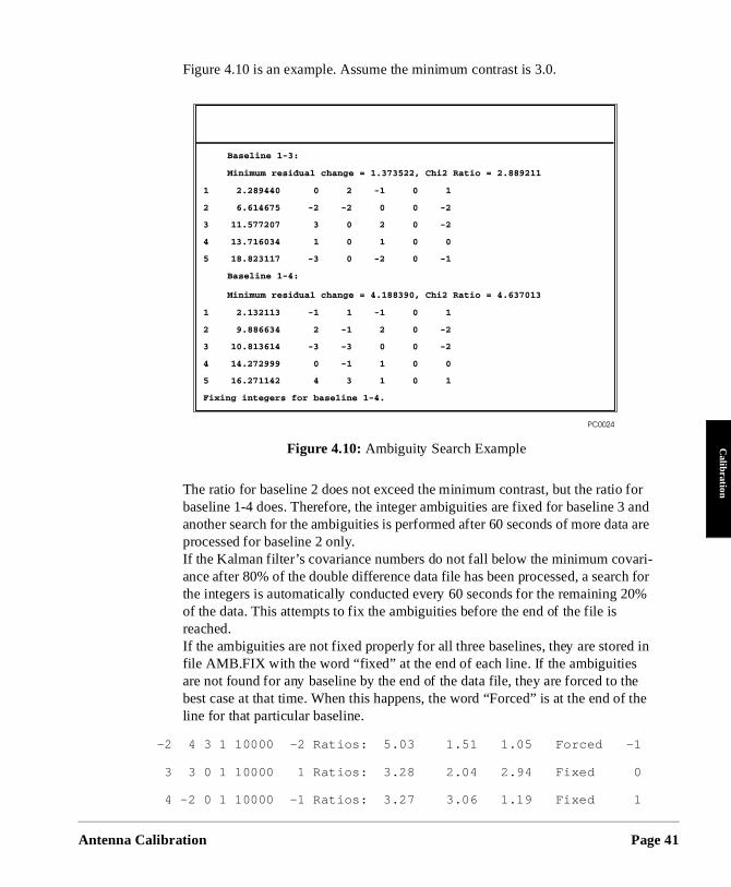
Figure 4.10 is an example. Assume the minimum contrast is 3.0.
The ratio for baseline 2 does not exceed the minimum contrast, but the ratiobaseline 1-4 does. Therefore, the integer ambiguities are fixed for baseline 3 aanother search for the ambiguities is performed after 60 seconds of more daprocessed for baseline 2 only. If the Kalman filter’s covariance numbers do not fall below the minimum covaance after 80% of the double difference data file has been processed, a searthe integers is automatically conducted every 60 seconds for the remaining of the data. This attempts to fix the ambiguities before the end of the file is reached. If the ambiguities are not fixed properly for all three baselines, they are storefile AMB.FIX with the word “fixed” at the end of each line. If the ambiguities are not found for any baseline by the end of the data file, they are forced to thebest case at that time. When this happens, the word “Forced” is at the end oline for that particular baseline.
-2 4 3 1 10000 -2 Ratios: 5.03 1.51 1.05 Forced -1
3 3 0 1 10000 1 Ratios: 3.28 2.04 2.94 Fixed 0
4 -2 0 1 10000 -1 Ratios: 3.27 3.06 1.19 Fixed 1
Figure 4.10: Ambiguity Search Example
alibration Page 41
Page 42
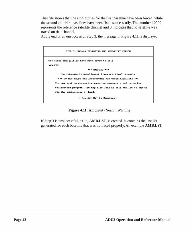
hile 000 s
d:
This file shows that the ambiguities for the first baseline have been forced, wthe second and third baselines have been fixed successfully. The number 10represents the reference satellite channel and 0 indicates that no satellite watraced on that channel. At the end of an unsuccessful Step 3, the message in Figure 4.11 is displaye
If Step 3 is unsuccessful, a file, AMB.LST , is created. It contains the last list generated for each baseline that was not fixed properly. An example AMB.LST
Figure 4.11: Ambiguity Search Warning
ADU2 Operation and Reference Manual
Antenna C
Calibration
. ber llite
gers ot
st idual d han ate
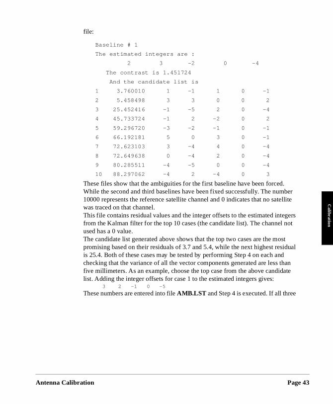
file:
Baseline # 1
The estimated integers are :
2 3 -2 0 -4
The contrast is 1.451724
And the candidate list is
1 3.760010 1 -1 1 0 -1
2 5.458498 3 3 0 0 2
3 25.452416 -1 -5 2 0 -4
4 45.733724 -1 2 -2 0 2
5 59.296720 -3 -2 -1 0 -1
6 66.192181 5 0 3 0 -1
7 72.623103 3 -4 4 0 -4
8 72.649638 0 -4 2 0 -4
9 80.285511 -4 -5 0 0 -4
10 88.297062 -4 2 -4 0 3
These files show that the ambiguities for the first baseline have been forcedWhile the second and third baselines have been fixed successfully. The num10000 represents the reference satellite channel and 0 indicates that no satewas traced on that channel.This file contains residual values and the integer offsets to the estimated intefrom the Kalman filter for the top 10 cases (the candidate list). The channel nused has a 0 value.The candidate list generated above shows that the top two cases are the mopromising based on their residuals of 3.7 and 5.4, while the next highest resis 25.4. Both of these cases may be tested by performing Step 4 on each anchecking that the variance of all the vector components generated are less tfive millimeters. As an example, choose the top case from the above candidlist. Adding the integer offsets for case 1 to the estimated integers gives: 3 2 -1 0 -5
These numbers are entered into file AMB.LST and Step 4 is executed. If all three
alibration Page 43
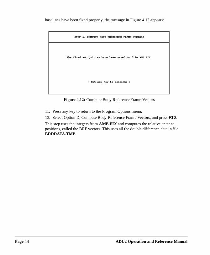
Page 44
file
baselines have been fixed properly, the message in Figure 4.12 appears:
11. Press any key to return to the Program Options menu.
12. Select Option D, Compute Body Reference Frame Vectors, and press F10.
This step uses the integers from AMB.FIX and computes the relative antenna positions, called the BRF vectors. This uses all the double difference data inBDDDATA.TMP .
Figure 4.12: Compute Body Reference Frame Vectors
ADU2 Operation and Reference Manual
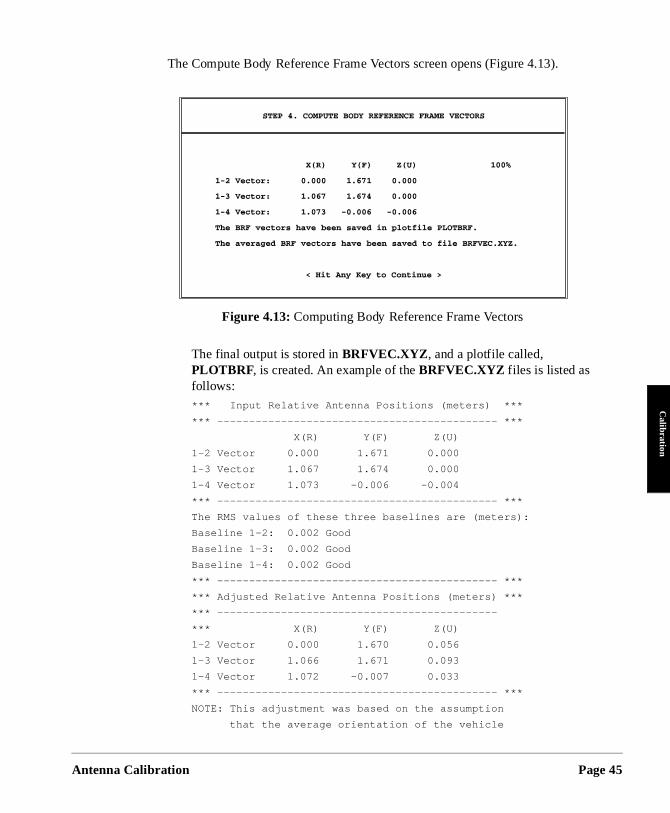
Antenna C
Calibration
The Compute Body Reference Frame Vectors screen opens (Figure 4.13).
The final output is stored in BRFVEC.XYZ , and a plotfile called, PLOTBRF, is created. An example of the BRFVEC.XYZ files is listed as follows: *** Input Relative Antenna Positions (meters) ***
*** -------------------------------------------- ***
X(R) Y(F) Z(U)
1-2 Vector 0.000 1.671 0.000
1-3 Vector 1.067 1.674 0.000
1-4 Vector 1.073 -0.006 -0.004
*** -------------------------------------------- ***
The RMS values of these three baselines are (meters):
Baseline 1-2: 0.002 Good
Baseline 1-3: 0.002 Good
Baseline 1-4: 0.002 Good
*** -------------------------------------------- ***
*** Adjusted Relative Antenna Positions (meters) ***
*** --------------------------------------------
*** X(R) Y(F) Z(U)
1-2 Vector 0.000 1.670 0.056
1-3 Vector 1.066 1.671 0.093
1-4 Vector 1.072 -0.007 0.033
*** -------------------------------------------- ***
NOTE: This adjustment was based on the assumption
that the average orientation of the vehicle
Figure 4.13: Computing Body Reference Frame Vectors
alibration Page 45
Page 46
tion ed to
e n two
was level during the calibration. The pitch
and roll offset angle computed from this
adjustment are:
PITCH OFFSET ANGLE: 1.937 (degrees)
ROLL OFFSET ANGLE: -1.970 (degrees)
If the adjusted relative antenna positions
are used, no pitch or roll offset angles
are needed.
*** -------------------------------------------- ***
The nine numbers listed in Adjusted Relative Antenna Positions (meters) seclist the BRF vectors of antennas 1-2, 1-3, and 1-4, respectively. Three of theparameters are exactly 0.0, since only six independent parameters are needdescribe a platform with three vectors.
It is very likely that pitch and roll offset angles will be induced. Refer to Appendix B.
13. Press any key to return to the Program Options menu.
14. Press <Esc> several times to exit CALI3DF.
15. Start PPLOT by typing pplot <ENTER> at the DOS prompt. The plotfile is useful to judge whether the ambiguities have been fixed properly.
16. The main menu opens. Select the file plotbrf and press <ENTER>.
PPLOT plots the six non-zero parameters of the BRF vectors given in filPLOTBRF (Figure 4.14). A good solution should have a small variation oall six parameters, that is, the peak-to-peak error should be no more thancentimeter on the screen. The largest variation is usually in the z-components of the BRF vectors.
ADU2 Operation and Reference Manual
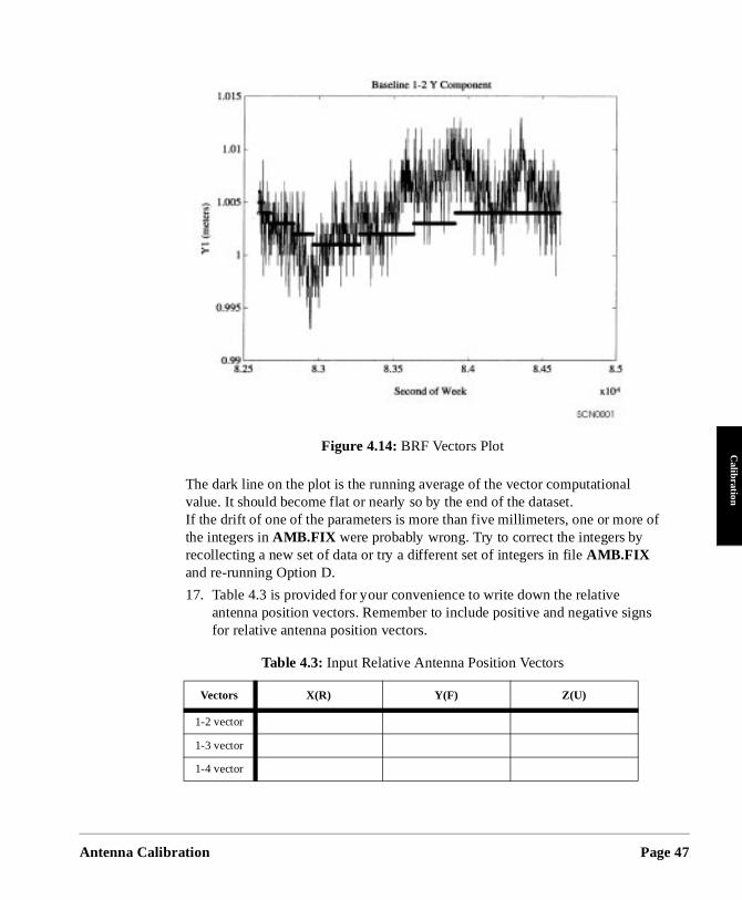
Antenna C
Calibration
of
gns
The dark line on the plot is the running average of the vector computational value. It should become flat or nearly so by the end of the dataset.If the drift of one of the parameters is more than five millimeters, one or morethe integers in AMB.FIX were probably wrong. Try to correct the integers by recollecting a new set of data or try a different set of integers in file AMB.FIX and re-running Option D.
17. Table 4.3 is provided for your convenience to write down the relative antenna position vectors. Remember to include positive and negative sifor relative antenna position vectors.
Figure 4.14: BRF Vectors Plot
Table 4.3: Input Relative Antenna Position Vectors
Vectors X(R) Y(F) Z(U)
1-2 vector
1-3 vector
1-4 vector
alibration Page 47
Page 48
a .
as 1 ore
as 1 ore
as 1 ore
ng
tem. If
ate es
e tly
Enter Relative Antenna Position Vectors Information
The final step in the dynamic calibration procedure is to enter the relative antennposition vectors using REMOTE or any other communications software package
1. Start REMOTE by typing remote <ENTER> at the DOS prompt.
2. Enter the relative antenna position vector for the vector between Antennand 2 by typing the following command. Be sure to enter + or - signs befeach number.
$PASHS,3DF,V12,+/-x.xx,+/-y.yy,+/-z.zz <ENTER>
3. Enter the relative antenna position vector for the vector between Antennand 3 by typing the following command. Be sure to enter + or - signs befeach number.
$PASHS,3DF,V13,+/-x.xx,+/-y.yy,+/-z.zz <ENTER>
4. Enter the relative antenna position vector for the vector between Antennand 4 by typing the following command. Be sure to enter + or - signs befeach number.
$PASHS,3DF,V14,+/-x.xx,+/-y.yy,+/-z.zz <ENTER>
5. Verify you entered the correct information including + and - signs by typi
$PASHQ,3DF
6. The system lists the relative antenna position vectors entered into the sysCheck these to verify you entered each vector into the system correctly.you made a mistake, you can reenter any of the three vectors.
7. After verifying you entered the vectors correctly, type $PASHS,SAV,Y to save the relative antenna position vector configuration in the receiver memory.
8. Press <ALT>x to exit Remote.
The dynamic calibration procedure is now complete. There is no need to recalibrthe ADU2 system unless you replace an antenna or if there has been any changmade to the relative positions of the antennas.
Dynamic Calibration-Run-Time Parameters
The Run-Time parameters are the parameters CALI3DF uses to process the data in the B-file for calibration. If the calculated body reference frame (BRF) vectors arpoor quality, the Run-Time parameters can be changed to process the data slighdifferently for better results.
ADU2 Operation and Reference Manual
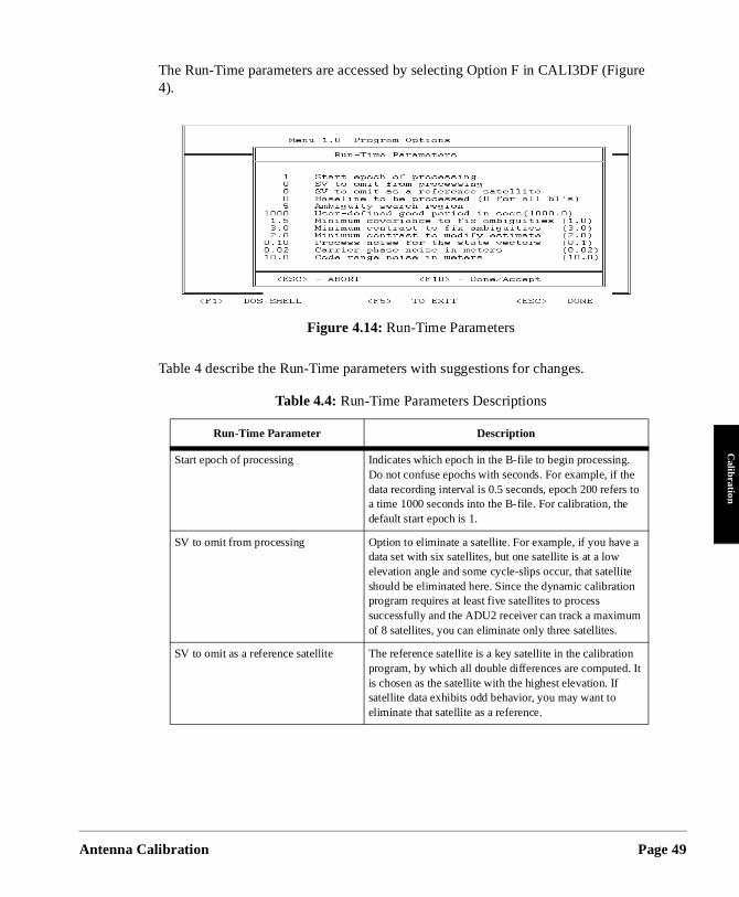
Antenna C
Calibration
re
The Run-Time parameters are accessed by selecting Option F in CALI3DF (Figu4).
Table 4 describe the Run-Time parameters with suggestions for changes.
Figure 4.14: Run-Time Parameters
Table 4.4: Run-Time Parameters Descriptions
Run-Time Parameter Description
Start epoch of processing Indicates which epoch in the B-file to begin processing. Do not confuse epochs with seconds. For example, if the data recording interval is 0.5 seconds, epoch 200 refers to a time 1000 seconds into the B-file. For calibration, the default start epoch is 1.
SV to omit from processing Option to eliminate a satellite. For example, if you have adata set with six satellites, but one satellite is at a low elevation angle and some cycle-slips occur, that satellite should be eliminated here. Since the dynamic calibration program requires at least five satellites to process successfully and the ADU2 receiver can track a maximum of 8 satellites, you can eliminate only three satellites.
SV to omit as a reference satellite The reference satellite is a key satellite in the calibrationprogram, by which all double differences are computed. It is chosen as the satellite with the highest elevation. If satellite data exhibits odd behavior, you may want to eliminate that satellite as a reference.
alibration Page 49
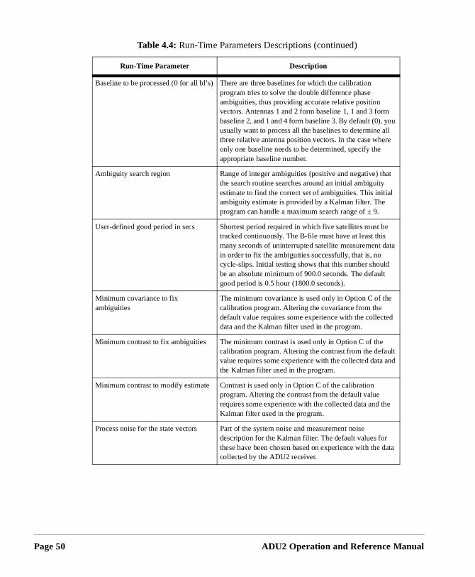
Page 50
Baseline to be processed (0 for all bl’s) There are three baselines for which the calibration program tries to solve the double difference phase ambiguities, thus providing accurate relative position vectors. Antennas 1 and 2 form baseline 1, 1 and 3 form baseline 2, and 1 and 4 form baseline 3. By default (0), you usually want to process all the baselines to determine all three relative antenna position vectors. In the case where only one baseline needs to be determined, specify the appropriate baseline number.
Ambiguity search region Range of integer ambiguities (positive and negative) that the search routine searches around an initial ambiguity estimate to find the correct set of ambiguities. This initial ambiguity estimate is provided by a Kalman filter. The program can handle a maximum search range of ± 9.
User-defined good period in secs Shortest period required in which five satellites must be tracked continuously. The B-file must have at least this many seconds of uninterrupted satellite measurement data in order to fix the ambiguities successfully, that is, no cycle-slips. Initial testing shows that this number should be an absolute minimum of 900.0 seconds. The default good period is 0.5 hour (1800.0 seconds).
Minimum covariance to fix ambiguities
The minimum covariance is used only in Option C of the calibration program. Altering the covariance from the default value requires some experience with the collected data and the Kalman filter used in the program.
Minimum contrast to fix ambiguities The minimum contrast is used only in Option C of the calibration program. Altering the contrast from the default value requires some experience with the collected data andthe Kalman filter used in the program.
Minimum contrast to modify estimate Contrast is used only in Option C of the calibration program. Altering the contrast from the default value requires some experience with the collected data and the Kalman filter used in the program.
Process noise for the state vectors Part of the system noise and measurement noise description for the Kalman filter. The default values for these have been chosen based on experience with the datacollected by the ADU2 receiver.
Table 4.4: Run-Time Parameters Descriptions (continued)
Run-Time Parameter Description
ADU2 Operation and Reference Manual
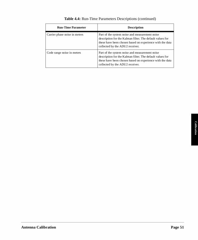
Antenna C
Calibration
Carrier phase noise in meters Part of the system noise and measurement noise description for the Kalman filter. The default values for these have been chosen based on experience with the datacollected by the ADU2 receiver.
Code range noise in meters Part of the system noise and measurement noise description for the Kalman filter. The default values for these have been chosen based on experience with the datacollected by the ADU2 receiver.
Table 4.4: Run-Time Parameters Descriptions (continued)
Run-Time Parameter Description
alibration Page 51

Page 52
ADU2 Operation and Reference Manual
5
Command Response FormatsCom
mand
Command
eiver,
er
ts A r l
f each
s from ) or a
Once the ADU2 has been calibrated and the offset vectors uploaded to the ADU2 recthe ADU2 is ready to output position velocity and attitude data.
Graphical displays of heading, pitch, roll, position, course over ground, and speed ovground are available in ADULOG (DOS) and EVALUATE (Windows). Refer to Chapter 7 for more information on ADULOG and the EVALUATE User’s Guide.
The ADU2 configuration and operation are controlled through two RS-232 ports (Porand B) by ASCII commands sent from the PC. You can use EVALUATE, REMOTE oany other commercial communications package, such as PROCOMM, to issue seriaCommands.
Inspect the NMEA and Raw Data output formats closely to determine which output messages are most applicable for the given application, and turn off the unuseful messages.
This chapter presents an overview of the command set, and a detailed explanation ocommand.
Overview
This section discusses the format and structure of the commands to and the responsethe ADU2. As noted previously, an external device such as a personal computer (PChandheld controller must be used to input commands to the sensor, and to monitor responses from the sensor. All commands must be terminated with <CR><LF> or <Enter> , as appropriate for the external device.
The commands and responses have the following headers:
Set Commands: $PASHS
Query Commands: $PASHQ
Responses: $PASHR
The commands and responses fall into the following functional categories:
Receiver Control Commands
Attitude Setup Commands
Attitude Control Commands
RTCM Differential Commands
NMEA Output Commands
RAW Data Commands
Response Formats Page 53
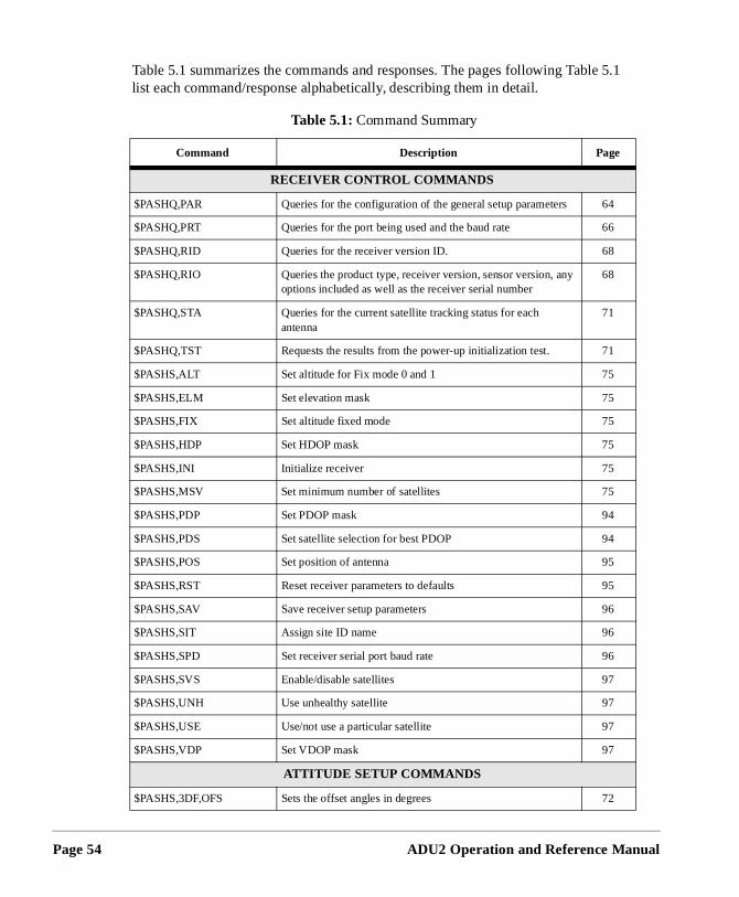
Page 54
5.1
Table 5.1 summarizes the commands and responses. The pages following Tablelist each command/response alphabetically, describing them in detail.Table 5.1: Command Summary
Command Description Page
RECEIVER CONTROL COMM ANDS
$PASHQ,PAR Queries for the configuration of the general setup parameters 64
$PASHQ,PRT Queries for the port being used and the baud rate 66
$PASHQ,RID Queries for the receiver version ID. 68
$PASHQ,RIO Queries the product type, receiver version, sensor version, any options included as well as the receiver serial number
68
$PASHQ,STA Queries for the current satellite tracking status for each antenna
71
$PASHQ,TST Requests the results from the power-up initialization test. 71
$PASHS,ALT Set altitude for Fix mode 0 and 1 75
$PASHS,ELM Set elevation mask 75
$PASHS,FIX Set altitude fixed mode 75
$PASHS,HDP Set HDOP mask 75
$PASHS,INI Initialize receiver 75
$PASHS,MSV Set minimum number of satellites 75
$PASHS,PDP Set PDOP mask 94
$PASHS,PDS Set satellite selection for best PDOP 94
$PASHS,POS Set position of antenna 95
$PASHS,RST Reset receiver parameters to defaults 95
$PASHS,SAV Save receiver setup parameters 96
$PASHS,SIT Assign site ID name 96
$PASHS,SPD Set receiver serial port baud rate 96
$PASHS,SVS Enable/disable satellites 97
$PASHS,UNH Use unhealthy satellite 97
$PASHS,USE Use/not use a particular satellite 97
$PASHS,VDP Set VDOP mask 97
ATTITUDE SETUP COMMANDS
$PASHS,3DF,OFS Sets the offset angles in degrees 72
ADU2 Operation and Reference Manual
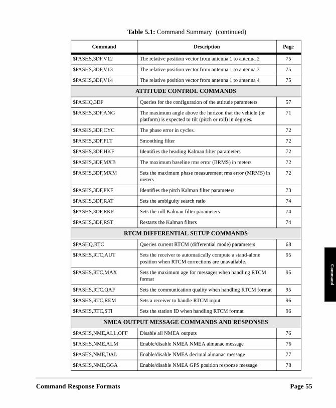
Command
Com
mand
$PASHS,3DF,V12 The relative position vector from antenna 1 to antenna 2 75
$PASHS,3DF,V13 The relative position vector from antenna 1 to antenna 3 75
$PASHS,3DF,V14 The relative position vector from antenna 1 to antenna 4 75
ATTITUDE CONTROL COMMANDS
$PASHQ,3DF Queries for the configuration of the attitude parameters 57
$PASHS,3DF,ANG The maximum angle above the horizon that the vehicle (or platform) is expected to tilt (pitch or roll) in degrees.
71
$PASHS,3DF,CYC The phase error in cycles. 72
$PASHS,3DF,FLT Smoothing filter 72
$PASHS,3DF,HKF Identifies the heading Kalman filter parameters 72
$PASHS,3DF,MXB The maximum baseline rms error (BRMS) in meters 72
$PASHS,3DF,MXM Sets the maximum phase measurement rms error (MRMS) in meters
72
$PASHS,3DF,PKF Identifies the pitch Kalman filter parameters 73
$PASHS,3DF,RAT Sets the ambiguity search ratio 74
$PASHS,3DF,RKF Sets the roll Kalman filter parameters 74
$PASHS,3DF,RST Restarts the Kalman filters 74
RTCM DIFFERENTIAL SETUP COMMANDS
$PASHQ,RTC Queries current RTCM (differential mode) parameters 68
$PASHS,RTC,AUT Sets the receiver to automatically compute a stand-alone position when RTCM corrections are unavailable.
95
$PASHS,RTC,MAX Sets the maximum age for messages when handling RTCM format
95
$PASHS,RTC,QAF Sets the communication quality when handling RTCM format 95
$PASHS,RTC,REM Sets a receiver to handle RTCM input 96
$PASHS,RTC,STI Sets the station ID when handling RTCM format 96
NMEA OUTPUT MESSAGE COMMANDS AND RESPONSES
$PASHS,NME,ALL,OFF Disable all NMEA outputs 76
$PASHS,NME,ALM Enable/disable NMEA NMEA almanac message 76
$PASHS,NME,DAL Enable/disable NMEA decimal almanac message 77
$PASHS,NME,GGA Enable/disable NMEA GPS position response message 78
Table 5.1: Command Summary (continued)
Command Description Page
Response Formats Page 55
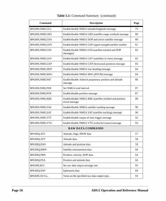
Page 56
$PASHS,NME,GLL Enable/disable NMEA latitude/longitude message 79
$PASHS,NME,GRS Enable/disable NMEA GRS (satellite range residual) message 80
$PASHS,NME,GSA Enable/disable NMEA DOP and active satellite message 80
$PASHS,NME,GSN Enable/disable NMEA GSN signal strength/satellite number 81
$PASHS,NME,GSS Enable/disable NMEA GSS (satellite tracked and DOP messages)
82
$PASHS,NME,GSV Enable/disable NMEA GSV (satellites in view) message 82
$PASHS,NME,GXP Enable/disable NMEA GXP (horizontal position) message 83
$PASHS,NME,HDT Enable/disable NMEA true heading message 84
$PASHS,NME,MSG Enable/disable NMEA MSG (RTCM) message 84
$PASHS,NME,PAT Enable/disable Ashtech proprietary position and altitude message
86
$PASHS,NME,PER Set NMEA send interval 87
$PASHS,NME,POS Enable/disable position message 87
$PASHS,NME,RRE Enable/disable NMEA RRE (satellite residual and position error) message
88
$PASHS,NME,SA4 Enable/disable NMEA satellite tracking message 90
$PASHS,NME,SAT Enable/disable NMEA SAT (satellite tracking) message 90
$PASHS,NME,TTT Enable/disable output of time trigger message 92
$PASHS,NME,VTG Enable/disable NMEA VTG (velocity/course) message 93
RAW DATA COM MANDS
$PASHQ,AT2 Attitude, flags, PDOP data 57
$PASHQ,ATT Attitude data 58
$PASHQ,DSO Attitude and position data 59
$PASHQ,MBN Satellite measurement data 60
$PASHQ,PBN Position, velocity, DOP data 64
$PASHQ,PSA Position and attitude data 66
$PASHS,RCI Set raw data output message rate 95
$PASHQ,SNV Ephemeris data 69
$PASHS,OUT,x, Turns on the specified raw data output type. 93
Table 5.1: Command Summary (continued)
Command Description Page
ADU2 Operation and Reference Manual
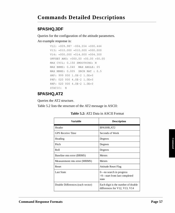
Command
Com
mand
Commands Detailed Descriptions
$PASHQ,3DF
Queries for the configuration of the attitude parameters.
An example response is: V12: +009.987 -004.554 +000.444
V13: +010.000 +010.000 +000.000
V14: +000.000 +014.000 +004.300
OFFSET ANG: +000.00 +00.00 +00.00
MAX CYCL: 0.150 SMOOTHING: N
MAX BRMS: 0.040 MAX ANGLE: 05
MAX MRMS: 0.005 SRCH RAT : 0.5
HKF: 999 000 1.0E-2 1.0E+0
PKF: 020 000 4.0E-2 1.0E+0
RKF: 020 000 4.0E-2 1.0E+0
STATIC: N
$PASHQ,AT2
Queries the AT2 structure.
Table 5.2 lists the structure of the AT2 message in ASCII:
Table 5.2: AT2 Data in ASCII Format
Variable Description
Header $PASHR,AT2
GPS Receive Time Seconds of Week
Heading Degrees
Pitch Degrees
Roll Degrees
Baseline rms error (BRMS) Meters
Measurement rms error (MRMS) Meters
Reset Attitude Reset Flag
Last State 0—no search in progress>0—start from last completed state
Double Differences (each vector) Each digit is the number of double differences for V12, V13, V14
Response Formats Page 57
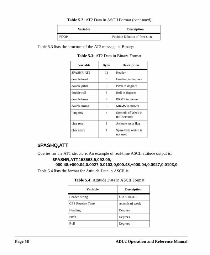
Page 58
Table 5.3 lists the structure of the AT2 message in Binary:
$PASHQ,ATT
Queries for the ATT structure. An example of real-time ASCII attitude output is:
$PASHR,ATT,153663.5,092.09,- 000.48,+000.04,0.0027,0.0103,0,000.48,+000.04,0.0027,0.0103,0
Table 5.4 lists the format for Attitude Data in ASCII is:
PDOP Position Dilution of Precision
Table 5.3: AT2 Data in Binary Format
Variable Bytes Description
$PASHR,AT2 11 Header
double head 8 Heading in degrees
double pitch 8 Pitch in degrees
double roll 8 Roll in degrees
double brms 8 BRMS in meters
double mrms 8 MRMS in meters
long tow 4 Seconds of Week in milliseconds
char reset 1 Attitude reset flag
char spare 1 Spare byte which is not used
Table 5.4: Attitude Data in ASCII Format
Variable Description
Header String $PASHR,ATT
GPS Receive Time seconds of week
Heading Degrees
Pitch Degrees
Roll Degrees
Table 5.2: AT2 Data in ASCII Format (continued)
Variable Description
ADU2 Operation and Reference Manual
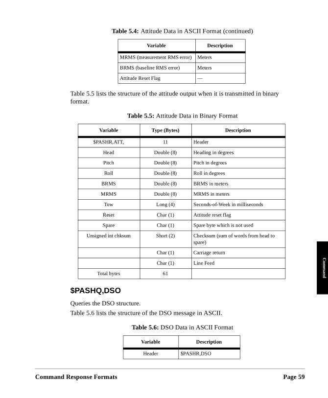
Command
Com
mand
Table 5.5 lists the structure of the attitude output when it is transmitted in binary format.
$PASHQ,DSO
Queries the DSO structure.
Table 5.6 lists the structure of the DSO message in ASCII.
MRMS (measurement RMS error) Meters
BRMS (baseline RMS error) Meters
Attitude Reset Flag —
Table 5.5: Attitude Data in Binary Format
Variable Type (Bytes) Description
$PASHR,ATT, 11 Header
Head Double (8) Heading in degrees
Pitch Double (8) Pitch in degrees
Roll Double (8) Roll in degrees
BRMS Double (8) BRMS in meters
MRMS Double (8) MRMS in meters
Tow Long (4) Seconds-of-Week in milliseconds
Reset Char (1) Attitude reset flag
Spare Char (1) Spare byte which is not used
Unsigned int chksum Short (2) Checksum (sum of words from head to spare)
Char (1) Carriage return
Char (1) Line Feed
Total bytes 61
Table 5.6: DSO Data in ASCII Format
Variable Description
Header $PASHR,DSO
Table 5.4: Attitude Data in ASCII Format (continued)
Variable Description
Response Formats Page 59
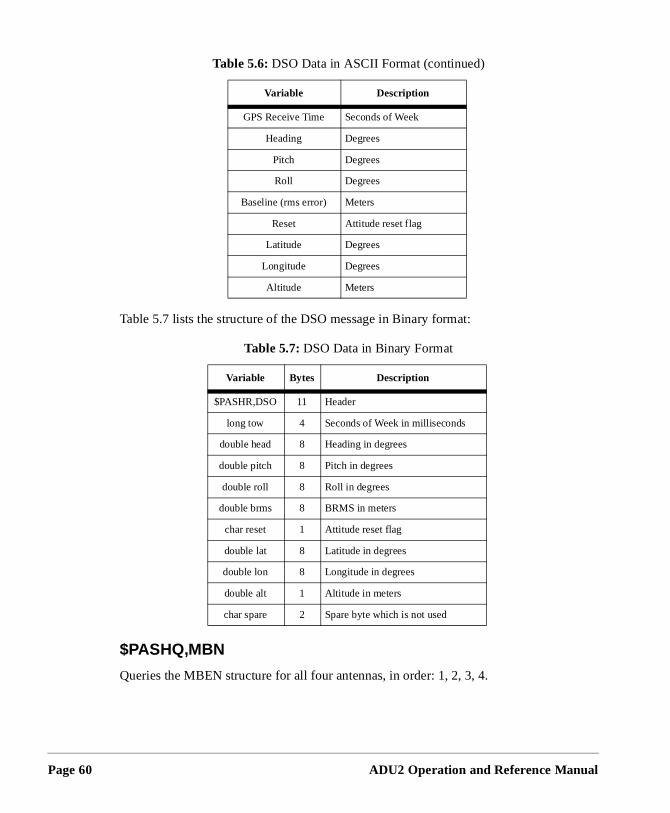
Page 60
Table 5.7 lists the structure of the DSO message in Binary format:
$PASHQ,MBN
Queries the MBEN structure for all four antennas, in order: 1, 2, 3, 4.
GPS Receive Time Seconds of Week
Heading Degrees
Pitch Degrees
Roll Degrees
Baseline (rms error) Meters
Reset Attitude reset flag
Latitude Degrees
Longitude Degrees
Altitude Meters
Table 5.7: DSO Data in Binary Format
Variable Bytes Description
$PASHR,DSO 11 Header
long tow 4 Seconds of Week in milliseconds
double head 8 Heading in degrees
double pitch 8 Pitch in degrees
double roll 8 Roll in degrees
double brms 8 BRMS in meters
char reset 1 Attitude reset flag
double lat 8 Latitude in degrees
double lon 8 Longitude in degrees
double alt 1 Altitude in meters
char spare 2 Spare byte which is not used
Table 5.6: DSO Data in ASCII Format (continued)
Variable Description
ADU2 Operation and Reference Manual
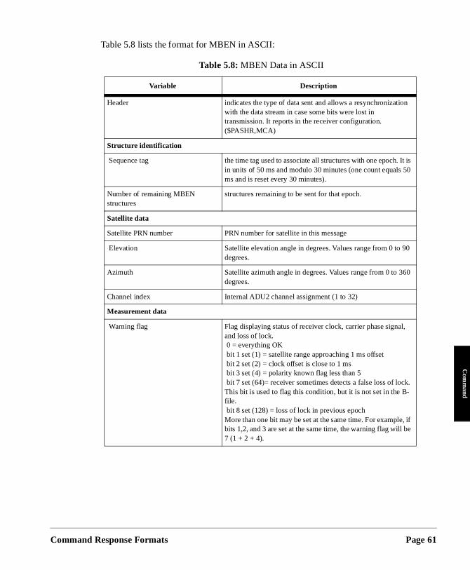
Command
Com
mand
t is
f
Table 5.8 lists the format for MBEN in ASCII:
Table 5.8: MBEN Data in ASCII
Variable Description
Header indicates the type of data sent and allows a resynchronizationwith the data stream in case some bits were lost in transmission. It reports in the receiver configuration. ($PASHR,MCA)
Structure identification
Sequence tag the time tag used to associate all structures with one epoch. Iin units of 50 ms and modulo 30 minutes (one count equals 50ms and is reset every 30 minutes).
Number of remaining MBEN structures
structures remaining to be sent for that epoch.
Satellite data
Satellite PRN number PRN number for satellite in this message
Elevation Satellite elevation angle in degrees. Values range from 0 to 90degrees.
Azimuth Satellite azimuth angle in degrees. Values range from 0 to 360degrees.
Channel index Internal ADU2 channel assignment (1 to 32)
Measurement data
Warning flag Flag displaying status of receiver clock, carrier phase signal, and loss of lock. 0 = everything OK bit 1 set (1) = satellite range approaching 1 ms offset bit 2 set (2) = clock offset is close to 1 ms bit 3 set (4) = polarity known flag less than 5 bit 7 set (64)= receiver sometimes detects a false loss of lock.This bit is used to flag this condition, but it is not set in the B-file. bit 8 set (128) = loss of lock in previous epoch More than one bit may be set at the same time. For example, ibits 1,2, and 3 are set at the same time, the warning flag will be 7 (1 + 2 + 4).
Response Formats Page 61
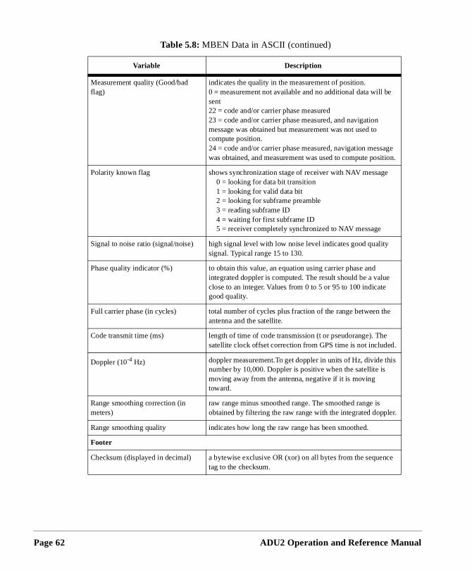
Page 62
.
e
Measurement quality (Good/bad flag)
indicates the quality in the measurement of position.0 = measurement not available and no additional data will be sent22 = code and/or carrier phase measured 23 = code and/or carrier phase measured, and navigation message was obtained but measurement was not used to compute position.24 = code and/or carrier phase measured, navigation messagewas obtained, and measurement was used to compute position
Polarity known flag shows synchronization stage of receiver with NAV message 0 = looking for data bit transition 1 = looking for valid data bit 2 = looking for subframe preamble 3 = reading subframe ID 4 = waiting for first subframe ID 5 = receiver completely synchronized to NAV message
Signal to noise ratio (signal/noise) high signal level with low noise level indicates good quality signal. Typical range 15 to 130.
Phase quality indicator (%) to obtain this value, an equation using carrier phase and integrated doppler is computed. The result should be a value close to an integer. Values from 0 to 5 or 95 to 100 indicate good quality.
Full carrier phase (in cycles) total number of cycles plus fraction of the range between theantenna and the satellite.
Code transmit time (ms) length of time of code transmission (t or pseudorange). The satellite clock offset correction from GPS time is not included.
Doppler (10-4 Hz) doppler measurement.To get doppler in units of Hz, divide this number by 10,000. Doppler is positive when the satellite is moving away from the antenna, negative if it is moving toward.
Range smoothing correction (in meters)
raw range minus smoothed range. The smoothed range is obtained by filtering the raw range with the integrated doppler.
Range smoothing quality indicates how long the raw range has been smoothed.
Footer
Checksum (displayed in decimal) a bytewise exclusive OR (xor) on all bytes from the sequenctag to the checksum.
Table 5.8: MBEN Data in ASCII (continued)
Variable Description
ADU2 Operation and Reference Manual
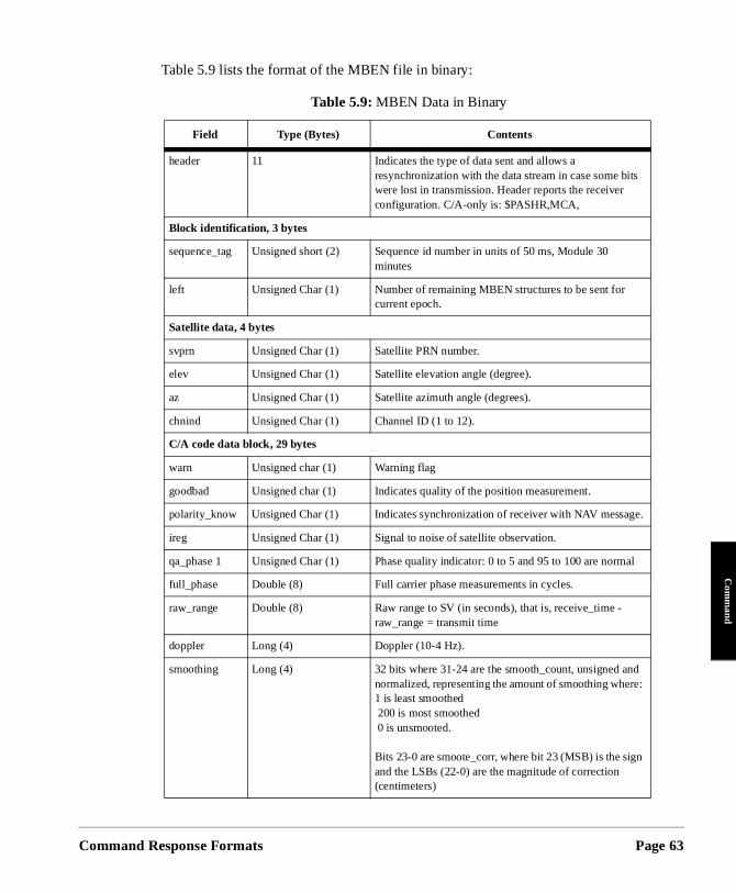
Command
Com
mand
.
l
Table 5.9 lists the format of the MBEN file in binary:
Table 5.9: MBEN Data in Binary
Field Type (Bytes) Contents
header 11 Indicates the type of data sent and allows a resynchronization with the data stream in case some bits were lost in transmission. Header reports the receiver configuration. C/A-only is: $PASHR,MCA,
Block identification, 3 bytes
sequence_tag Unsigned short (2) Sequence id number in units of 50 ms, Module 30 minutes
left Unsigned Char (1) Number of remaining MBEN structures to be sent for current epoch.
Satellite data, 4 bytes
svprn Unsigned Char (1) Satellite PRN number.
elev Unsigned Char (1) Satellite elevation angle (degree).
az Unsigned Char (1) Satellite azimuth angle (degrees).
chnind Unsigned Char (1) Channel ID (1 to 12).
C/A code data block, 29 bytes
warn Unsigned char (1) Warning flag
goodbad Unsigned char (1) Indicates quality of the position measurement.
polarity_know Unsigned Char (1) Indicates synchronization of receiver with NAV message
ireg Unsigned Char (1) Signal to noise of satellite observation.
qa_phase 1 Unsigned Char (1) Phase quality indicator: 0 to 5 and 95 to 100 are norma
full_phase Double (8) Full carrier phase measurements in cycles.
raw_range Double (8) Raw range to SV (in seconds), that is, receive_time - raw_range = transmit time
doppler Long (4) Doppler (10-4 Hz).
smoothing Long (4) 32 bits where 31-24 are the smooth_count, unsigned andnormalized, representing the amount of smoothing where: 1 is least smoothed 200 is most smoothed 0 is unsmooted.
Bits 23-0 are smoote_corr, where bit 23 (MSB) is the sign and the LSBs (22-0) are the magnitude of correction (centimeters)
Response Formats Page 63
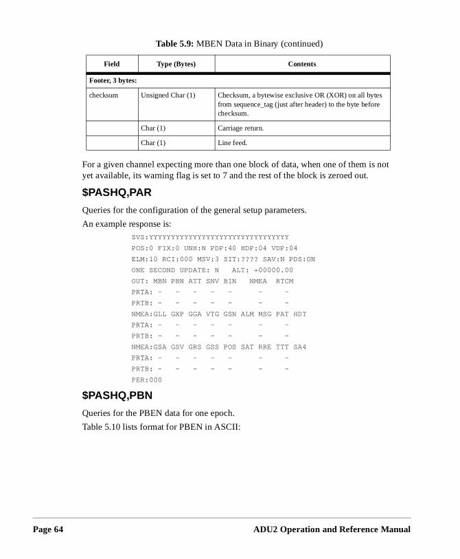
Page 64
not
For a given channel expecting more than one block of data, when one of them isyet available, its warning flag is set to 7 and the rest of the block is zeroed out.
$PASHQ,PAR
Queries for the configuration of the general setup parameters.
An example response is:SVS:YYYYYYYYYYYYYYYYYYYYYYYYYYYYYYYY
POS:0 FIX:0 UNH:N PDP:40 HDP:04 VDP:04
ELM:10 RCI:000 MSV:3 SIT:???? SAV:N PDS:ON
ONE SECOND UPDATE: N ALT: +00000.00
OUT: MBN PBN ATT SNV BIN NMEA RTCM
PRTA: - - - - - - -
PRTB: - - - - - - -
NMEA:GLL GXP GGA VTG GSN ALM MSG PAT HDT
PRTA: - - - - - - -
PRTB: - - - - - - -
NMEA:GSA GSV GRS GSS POS SAT RRE TTT SA4
PRTA: - - - - - - -
PRTB: - - - - - - -
PER:000
$PASHQ,PBN
Queries for the PBEN data for one epoch.
Table 5.10 lists format for PBEN in ASCII:
Footer, 3 bytes:
checksum Unsigned Char (1) Checksum, a bytewise exclusive OR (XOR) on all bytesfrom sequence_tag (just after header) to the byte before checksum.
Char (1) Carriage return.
Char (1) Line feed.
Table 5.9: MBEN Data in Binary (continued)
Field Type (Bytes) Contents
ADU2 Operation and Reference Manual
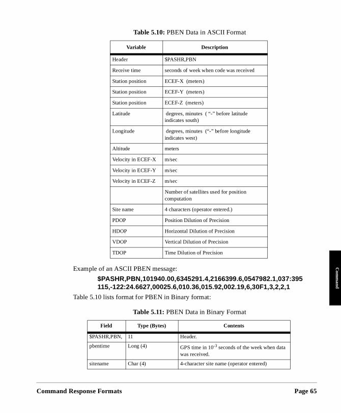
Command
Com
mand
Example of an ASCII PBEN message:
$PASHR,PBN,101940.00,6345291.4,2166399.6,0547982.1,037:395115,-122:24.6627,00025.6,010.36,015.92,002.19,6,30F1,3,2,2,1
Table 5.10 lists format for PBEN in Binary format:
Table 5.10: PBEN Data in ASCII Format
Variable Description
Header $PASHR,PBN
Receive time seconds of week when code was received
Station position ECEF-X (meters)
Station position ECEF-Y (meters)
Station position ECEF-Z (meters)
Latitude degrees, minutes ( “-” before latitude indicates south)
Longitude degrees, minutes (“-” before longitude indicates west)
Altitude meters
Velocity in ECEF-X m/sec
Velocity in ECEF-Y m/sec
Velocity in ECEF-Z m/sec
Number of satellites used for position computation
Site name 4 characters (operator entered.)
PDOP Position Dilution of Precision
HDOP Horizontal Dilution of Precision
VDOP Vertical Dilution of Precision
TDOP Time Dilution of Precision
Table 5.11: PBEN Data in Binary Format
Field Type (Bytes) Contents
$PASHR,PBN, 11 Header.
pbentime Long (4) GPS time in 10-3 seconds of the week when data was received.
sitename Char (4) 4-character site name (operator entered)
Response Formats Page 65
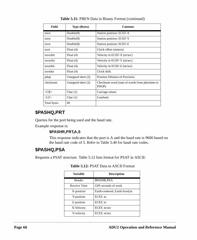
Page 66
d on
$PASHQ,PRT
Queries for the port being used and the baud rate.
Example response is:
$PASHR,PRT,A,5
This response indicates that the port is A and the baud rate is 9600 basethe baud rate code of 5. Refer to Table 5.40 for baud rate codes.
$PASHQ,PSA
Requests a PSAT structure. Table 5.12 lists format for PSAT in ASCII:
navx Double(8) Station position: ECEF-X
navy Double(8) Station position: ECEF-Y
navz Double(8) Station position: ECEF-Z
navt Float (4) Clock offset (meters).
navxdot Float (4) Velocity in ECEF-X (m/sec)
navydot Float (4) Velocity in ECEF-Y (m/sec)
navzdot Float (4) Velocity in ECEF-Z (m/sec)
navtdot Float (4) Clock drift.
pdop Unsigned short (2) Position Dilution of Precision
checksum Unsigned short (2) Checksum word (sum of words from pbentime to PDOP)
<CR> Char (1) Carriage return.
<LF> Char (1) Linefeed.
Total bytes 69
Table 5.12: PSAT Data in ASCII Format
Variable Description
Header $PASHR,PSA
Receive Time GPS seconds of week
X-position Earth-centered, Earth-fixed,m
Y-position ECEF, m
Z-position ECEF, m
X-Velocity ECEF, m/sec
Y-velocity ECEF, m/sec
Table 5.11: PBEN Data in Binary Format (continued)
Field Type (Bytes) Contents
ADU2 Operation and Reference Manual
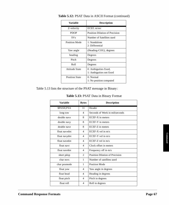
Command
Com
mand
Table 5.13 lists the structure of the PSAT message in Binary:
Z-velocity ECEF, m/sec
PDOP Position Dilution of Precision
SVs Number of Satellites used
Position Mode 1: Standalone2: Differential
Yaw angle (Heading-COG), degrees
heading Degrees
Pitch Degrees
Roll Degrees
Attitude State 0: Ambiguities fixed,1: Ambiguities not fixed
Position State 0: Normal1: No position computed
Table 5.13: PSAT Data in Binary Format
Variable Bytes Description
$PASH,PSA 11 Header
long tow 4 Seconds of Week in miliseconds
double navx 8 ECEF-X in meters
double navy 8 ECEF-Y in meters
double navz 8 ECEF-Z in meters
float navxdot 4 ECEF-X vel in m/s
float navydot 4 ECEF-Y vel in m/s
float navzdot 4 ECEF-Z vel in m/s
float navt 4 Clock offset in meters
float navtdot 4 Frequency off in m/s
short pdop 2 Position Dilution of Precision
char nsvs 1 Number of satellites used
char posmode 1 Position Mode
float yaw 4 Yaw angle in degrees
float head 4 Heading in degrees
float pitch 4 Pitch in degrees
float roll 4 Roll in degrees
Table 5.12: PSAT Data in ASCII Format (continued)
Variable Description
Response Formats Page 67
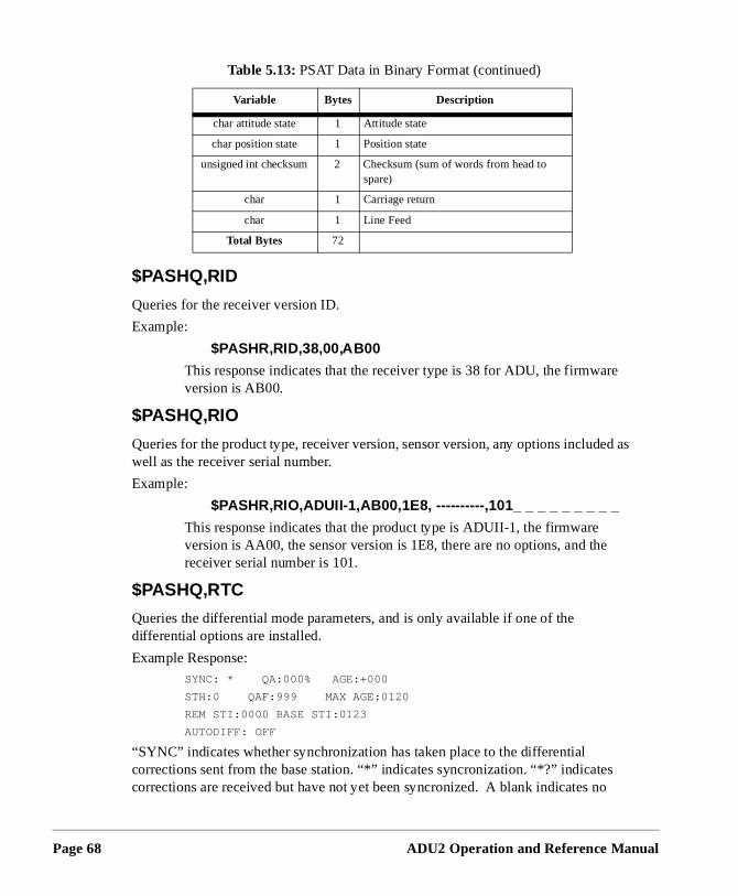
Page 68
e
ed as
o
$PASHQ,RID
Queries for the receiver version ID.
Example:
$PASHR,RID,38,00,AB00
This response indicates that the receiver type is 38 for ADU, the firmwarversion is AB00.
$PASHQ,RIO
Queries for the product type, receiver version, sensor version, any options includwell as the receiver serial number.
Example:
$PASHR,RIO,ADUII-1,AB00,1E8, ----------,101_ _ _ _ _ _ _ _ _
This response indicates that the product type is ADUII-1, the firmware version is AA00, the sensor version is 1E8, there are no options, and thereceiver serial number is 101.
$PASHQ,RTC
Queries the differential mode parameters, and is only available if one of the differential options are installed.
Example Response:SYNC: * QA:000% AGE:+000
STH:0 QAF:999 MAX AGE:0120
REM STI:0000 BASE STI:0123
AUTODIFF: OFF
“SYNC” indicates whether synchronization has taken place to the differential corrections sent from the base station. “*” indicates syncronization. “*?” indicatescorrections are received but have not yet been syncronized. A blank indicates n
char attitude state 1 Attitude state
char position state 1 Position state
unsigned int checksum 2 Checksum (sum of words from head to spare)
char 1 Carriage return
char 1 Line Feed
Total Bytes 72
Table 5.13: PSAT Data in Binary Format (continued)
Variable Bytes Description
ADU2 Operation and Reference Manual
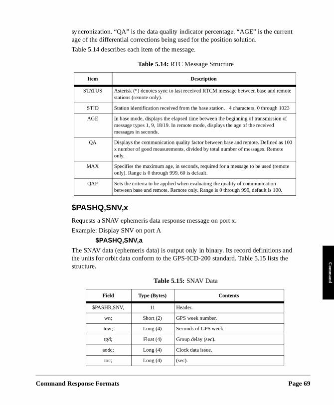
Command
Com
mand
t
ote
f
00
te
syncronization. “QA” is the data quality indicator percentage. “AGE” is the currenage of the differential corrections being used for the position solution.
Table 5.14 describes each item of the message.
$PASHQ,SNV,x
Requests a SNAV ephemeris data response message on port x.
Example: Display SNV on port A
$PASHQ,SNV,a
The SNAV data (ephemeris data) is output only in binary. Its record definitions and the units for orbit data conform to the GPS-ICD-200 standard. Table 5.15 lists the structure.
Table 5.14: RTC Message Structure
Item Description
STATUS Asterisk (*) denotes sync to last received RTCM message between base and remstations (remote only).
STID Station identification received from the base station. 4 characters, 0 through 1023
AGE In base mode, displays the elapsed time between the beginning of transmission omessage types 1, 9, 18/19. In remote mode, displays the age of the received messages in seconds.
QA Displays the communication quality factor between base and remote. Defined as 1x number of good measurements, divided by total number of messages. Remote only.
MAX Specifies the maximum age, in seconds, required for a message to be used (remoonly). Range is 0 through 999, 60 is default.
QAF Sets the criteria to be applied when evaluating the quality of communication between base and remote. Remote only. Range is 0 through 999, default is 100.
Table 5.15: SNAV Data
Field Type (Bytes) Contents
$PASHR,SNV, 11 Header.
wn; Short (2) GPS week number.
tow; Long (4) Seconds of GPS week.
tgd; Float (4) Group delay (sec).
aodc; Long (4) Clock data issue.
toc; Long (4) (sec).
Response Formats Page 69
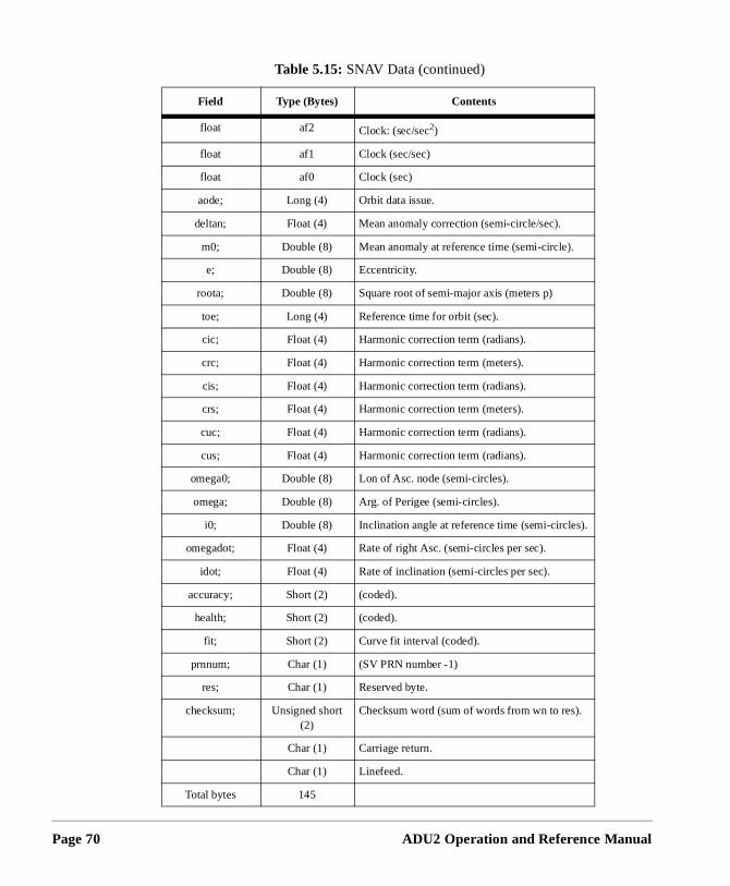
Page 70
float af2 Clock: (sec/sec2)
float af1 Clock (sec/sec)
float af0 Clock (sec)
aode; Long (4) Orbit data issue.
deltan; Float (4) Mean anomaly correction (semi-circle/sec).
m0; Double (8) Mean anomaly at reference time (semi-circle).
e; Double (8) Eccentricity.
roota; Double (8) Square root of semi-major axis (meters p)
toe; Long (4) Reference time for orbit (sec).
cic; Float (4) Harmonic correction term (radians).
crc; Float (4) Harmonic correction term (meters).
cis; Float (4) Harmonic correction term (radians).
crs; Float (4) Harmonic correction term (meters).
cuc; Float (4) Harmonic correction term (radians).
cus; Float (4) Harmonic correction term (radians).
omega0; Double (8) Lon of Asc. node (semi-circles).
omega; Double (8) Arg. of Perigee (semi-circles).
i0; Double (8) Inclination angle at reference time (semi-circles).
omegadot; Float (4) Rate of right Asc. (semi-circles per sec).
idot; Float (4) Rate of inclination (semi-circles per sec).
accuracy; Short (2) (coded).
health; Short (2) (coded).
fit; Short (2) Curve fit interval (coded).
prnnum; Char (1) (SV PRN number -1)
res; Char (1) Reserved byte.
checksum; Unsigned short (2)
Checksum word (sum of words from wn to res).
Char (1) Carriage return.
Char (1) Linefeed.
Total bytes 145
Table 5.15: SNAV Data (continued)
Field Type (Bytes) Contents
ADU2 Operation and Reference Manual
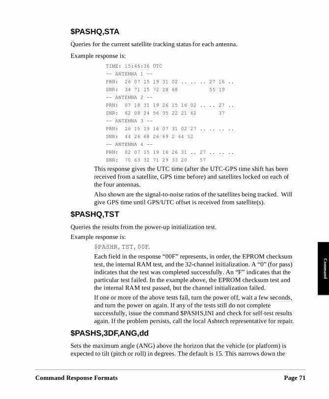
Command
Com
mand
en of
Will
sum s) the and
ds,
ults pair.
is e
$PASHQ,STA
Queries for the current satellite tracking status for each antenna.
Example response is:
TIME: 15:46:36 UTC
-- ANTENNA 1 --
PRN: 26 07 15 19 31 02 .. .. .. 27 16 ..
SNR: 34 71 15 72 28 68 55 19
-- ANTENNA 2 --
PRN: 07 18 31 19 26 15 16 02 .. .. 27 ..
SNR: 62 08 24 56 35 22 21 62 37
-- ANTENNA 3 --
PRN: 26 15 19 16 07 31 02 27 .. .. .. ..
SNR: 44 26 68 26 69 2 64 52
-- ANTENNA 4 --
PRN: 02 07 15 19 16 26 31 .. 27 .. .. ..
SNR: 70 63 32 71 29 33 20 57
This response gives the UTC time (after the UTC-GPS time shift has bereceived from a satellite, GPS time before) and satellites locked on eachthe four antennas.
Also shown are the signal-to-noise ratios of the satellites being tracked. give GPS time until GPS/UTC offset is received from satellite(s).
$PASHQ,TST
Queries the results from the power-up initialization test.
Example response is:
$PASHR,TST,00F .
Each field in the response “00F” represents, in order, the EPROM checktest, the internal RAM test, and the 32-channel initialization. A “0” (for pasindicates that the test was completed successfully. An “F” indicates that particular test failed. In the example above, the EPROM checksum test the internal RAM test passed, but the channel initialization failed.
If one or more of the above tests fail, turn the power off, wait a few seconand turn the power on again. If any of the tests still do not complete successfully, issue the command $PASHS,INI and check for self-test resagain. If the problem persists, call the local Ashtech representative for re
$PASHS,3DF,ANG,dd
Sets the maximum angle (ANG) above the horizon that the vehicle (or platform) expected to tilt (pitch or roll) in degrees. The default is 15. This narrows down th
Response Formats Page 71
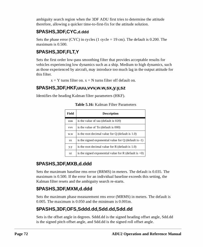
Page 72
e
uch e for
he
lt is
dd.dd
ambiguity search region when the 3DF ADU first tries to determine the attitude therefore, allowing a quicker time-to-first-fix for the attitude solution.
$PASHS,3DF,CYC,d.ddd
Sets the phase error (CYC) in cycles (1 cycle = 19 cm). The default is 0.200. Thmaximum is 0.500.
$PASHS,3DF,FLT,Y
Sets the first order low-pass smoothing filter that provides acceptable results forvehicles experiencing low dynamics such as a ship. Medium to high dynamics, sas those experienced by aircraft, may introduce too much lag in the output attitudthis filter.
x = Y turns filter on. x = N turns filter off default on.
$PASHS,3DF,HKF,uuu,vvv,w.w,sx,y.y,sz
Identifies the heading Kalman filter parameters (HKF).
$PASHS,3DF,MXB,d.ddd
Sets the maximum baseline rms error (BRMS) in meters. The default is 0.035. Tmaximum is 0.500. If the error for an individual baseline exceeds this setting, theKalman filter resets and the ambiguity search re-starts.
$PASHS,3DF,MXM,d.ddd
Sets the maximum phase measurement rms error (MRMS) in meters. The defau0.005. The maximum is 0.050 and the minimum is 0.001m.
$PASHS,3DF,OFS,Sddd.dd,Sdd.dd,Sdd.dd
Sets is the offset angle in degrees. Sddd.dd is the signed heading offset angle, Sis the signed pitch offset angle, and Sdd.dd is the signed roll offset angle.
Table 5.16: Kalman Filter Parameters
Field Description
uuu is the value of tau (default is 020)
vvv is the value of To (default is 000)
w.w is the root decimal value for Q (default is 1.0)
sx is the signed exponential value for Q (default is -1)
y.y is the root decimal value for R (default is 1.0)
sz is the signed exponential value for R (default is +0)
ADU2 Operation and Reference Manual
Command
Com
mand
n to d by
ed
one
is
ctly 1 to e a ined
dict and l
f a
es ts
re
hen
The offset rotation angles (in degrees) align the 3DF attitude measurements givethe desired vehicle coordinate system. These rotation angles must be determinesome other accurate measurement device.
OFFSETS: heading(H), pitch(P), roll(R)
The offset rotation angles are normally 0.0. These numbers should not be changunless you have a case such as the following:
Occasionally mounting restrictions may require the antennas to be located from another such that the surveyed relative antenna position vectors (from file BRFVEC.XYZ) do not directly provide the vehicle’s angular rotations (heading, pitch, roll). In this situation, some other form of accurate measurement capabilityrequired to measure the offset angles (for example, a tape measure or a gyro-theodolite).
For example, suppose that Antenna 1 and Antenna 2 could not be mounted exaalong the heading direction of the vehicle and you chose the vector from AntennaAntenna 2 to provide heading information. The installation software can determin1-2 relative antenna position vector, but the heading offset angle must be determwith another precise measurement technique.
$PASHS,3DF,PKF,uuu,vvv,w.w,sx,y.y,sz
Sets the pitch Kalman filter parameters.
Three two-state Kalman filters are implemented in the ADU software to help prean approximate attitude of the vehicle at the current epoch. They are a heading heading rate filter, a pitch and pitch rate filter, and a roll and roll rate filter. SeveraKalman filter variables for heading, pitch, and roll are described below:
• tau: Correlation time (sec) (default values are 999, 20, 20) - Any numbergreater than 500 or 000 implies that the system model is an integration orandom-walk process (or a constant velocity model).
• To: Oscillation period (seconds) (default values are 0, 0, 0.) A zero implithat no oscillation exists. For ship installations, an oscillation period exisfor both pitch and roll. This information aids the Kalman filter.
• Q: Process noise power spectral density [(radian/sec2)2*sec] (Defaults a1.0e-2, 4.0e-2, 4.0e-2). The default values are valid for low to medium vehicle dynamics. High dynamics require higher values, such as 1.0.
• R: Measurement noise scale factor (defaults are 1, 1, 1) • These variables may need tuning depending on the vehicle dynamics. W
set properly, the variables help the Kalman filter give a good estimate of
Response Formats Page 73
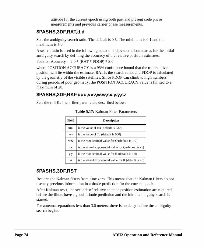
Page 74
ted
not
ired is
guity
attitude for the current epoch using both past and present code phase measurements and previous carrier phase measurements.
$PASHS,3DF,RAT,d.d
Sets the ambiguity search ratio. The default is 0.5. The minimum is 0.1 and the maximum is 5.0.
A search ratio is used in the following equation helps set the boundaries for the initial ambiguity search by defining the accuracy of the relative position estimates.
Position Accuracy = 2.0 * (RAT * PDOP) * 3.0
where POSITION ACCURACY is a 95% confidence bound that the true relative position will lie within the estimate, RAT is the search ratio, and PDOP is calculaby the geometry of the visible satellites. Since PDOP can climb to high numbersduring periods of poor geometry, the POSITION ACCURACY value is limited to a maximum of 20.
$PASHS,3DF,RKF,uuu,vvv,w.w,sx,y.y,sz
Sets the roll Kalman filter parameters described below:
$PASHS,3DF,RST
Restarts the Kalman filters from time zero. This means that the Kalman filters douse any previous information in attitude prediction for the current epoch.
After Kalman reset, ten seconds of relative antenna position estimation are requbefore the filters have a good attitude prediction and the initial ambiguity search started.
For antenna separations less than 3.0 meters, there is no delay before the ambisearch begins.
Table 5.17: Kalman Filter Parameters
Field Description
uuu is the value of tau (default is 020)
vvv is the value of To (default is 000)
w.w is the root decimal value for Q (default is 1.0)
sx is the signed exponential value for Q (default is -1)
y.y is the root decimal value for R (default is 1.0)
sz is the signed exponential value for R (default is +0)
ADU2 Operation and Reference Manual
Command
Com
mand
and
and
and
+ or -
n be
nd.
. .
rs to quent
$PASHS,3DF,V12,Sddd.ddd,Sddd.ddd,Sddd.ddd
Sets the relative position vector from antenna 1 to antenna 2. S is the sign (+/-), ddd.ddd are the X, Y, and Z position vector components in meters.
$PASHS,3DF,V13,Sddd.ddd,Sddd.ddd,Sddd.ddd
Sets the relative position vector from antenna 1 to antenna 3. S is the sign (+/-), ddd.ddd are the X, Y, and Z position vector components in meters.
$PASHS,3DF,V14,Sddd.ddd,Sddd.ddd,Sddd.ddd
Sets the relative position vector from antenna 1 to antenna 4. S is the sign (+/-), ddd.ddd are the X, Y, and Z position vector components in meters. Initially, this vector is +000.000.
$PASHS,ALT,Sxxxxx.xx
Sets the altitude of antenna 1, where Sxxxxx.xx is the altitude and S is the sign (). This is used in conjunction with Position Mode 1, 2, and 3.
$PASHS,ELM,dd
Sets the elevation mask in degrees. The default is 10.
$PASHS,FIX,d
Sets the altitude-fixed mode for the position computation.
0 (default) - indicates to use the most recent computed altitude which cathe last one computed when VDOP is less than VDOP mask, or the oneentered by ALT.
1 - indicates to always use the altitude entered by the ALT input comma
$PASHS,HDP,dd
Sets the HDOP (horizontal dilution of precision) mask for the position computationA position is not computed if the HDOP rises above this number. The default is 4
$PASHS,INI
Resets the internal memory of the receiver and resets all configuration parametetheir defaults. Wait 20 seconds after issuing this command before sending subsecommands.
$PASHS,MSV,dd
Sets the minimum number of satellites to record. The default is 3.
Response Formats Page 75
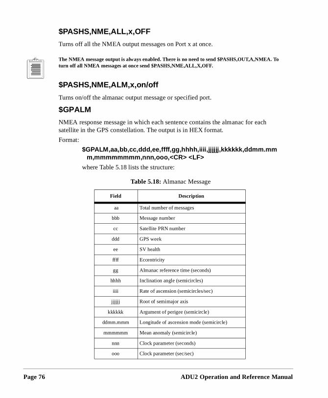
Page 76
h
$PASHS,NME,ALL,x,OFF
Turns off all the NMEA output messages on Port x at once.
The NMEA message output is always enabled. There is no need to send $PASHS,OUT,A,NMEA. Toturn off all NMEA messages at once send $PASHS,NME,ALL,X,OFF.
$PASHS,NME,ALM,x,on/off
Turns on/off the almanac output message or specified port.
$GPALM
NMEA response message in which each sentence contains the almanac for eacsatellite in the GPS constellation. The output is in HEX format.
Format:
$GPALM,aa,bb,cc,ddd,ee,ffff,gg,hhhh,iiii,jjjjjj,kkkkkk,ddmm.mmm,mmmmmmmm,nnn,ooo,<CR> <LF>
where Table 5.18 lists the structure:
Table 5.18: Almanac Message
Field Description
aa Total number of messages
bbb Message number
cc Satellite PRN number
ddd GPS week
ee SV health
ffff Eccentricity
gg Almanac reference time (seconds)
hhhh Inclination angle (semicircles)
iiii Rate of ascension (semicircles/sec)
jjjjjj Root of semimajor axis
kkkkkk Argument of perigee (semicircle)
ddmm.mmm Longitude of ascension mode (semicircle)
mmmmmm Mean anomaly (semicircle)
nnn Clock parameter (seconds)
ooo Clock parameter (sec/sec)
ADU2 Operation and Reference Manual
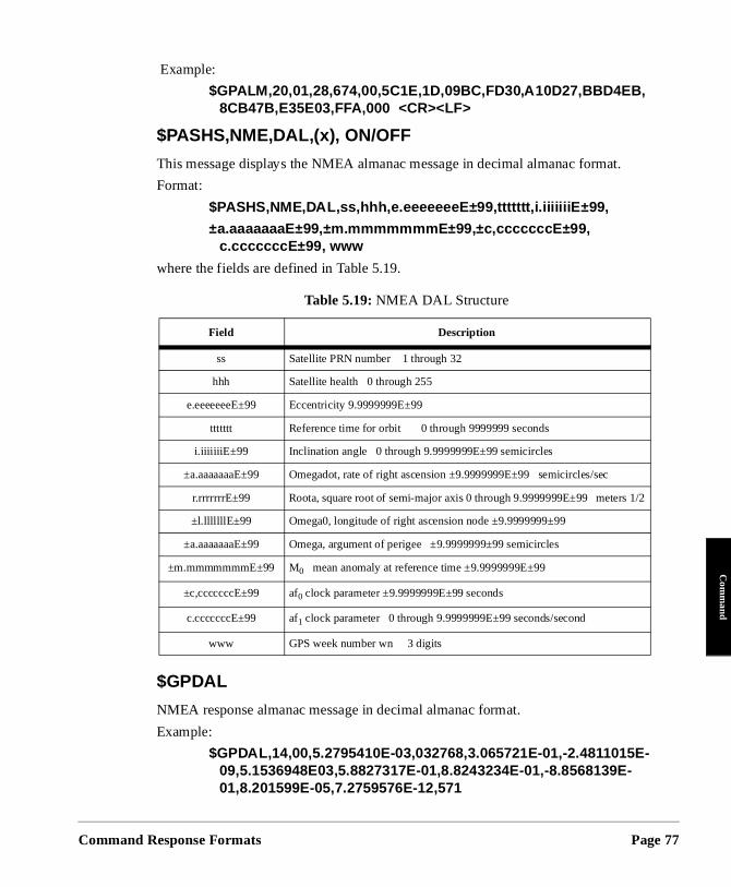
Command
Com
mand
.
Example:
$GPALM,20,01,28,674,00,5C1E,1D,09BC,FD30,A10D27,BBD4EB, 8CB47B,E35E03,FFA,000 <CR><LF>
$PASHS,NME,DAL,(x), ON/OFF
This message displays the NMEA almanac message in decimal almanac format
Format:
$PASHS,NME,DAL,ss,hhh,e.eeeeeeeE±99,ttttttt,i.iiiiiiiE ±99,
±a.aaaaaaaE±99,±m.m mmmmmm E±99,±c, cccccccE±99, c.ccccccc E±99, www
where the fields are defined in Table 5.19.
$GPDAL
NMEA response almanac message in decimal almanac format.
Example:
$GPDAL,14,00,5.2795410E-03,032768,3.065721E-01,-2.4811015E-09,5.1536948E03,5.8827317E-01,8.8243234E-01,-8.8568139E-01,8.201599E-05,7.2759576E-12,571
Table 5.19: NMEA DAL Structure
Field Description
ss Satellite PRN number 1 through 32
hhh Satellite health 0 through 255
e.eeeeeeeE±99 Eccentricity 9.9999999E±99
ttttttt Reference time for orbit 0 through 9999999 seconds
i.iiiiiiiE±99 Inclination angle 0 through 9.9999999E±99 semicircles
±a.aaaaaaaE±99 Omegadot, rate of right ascension ±9.9999999E±99 semicircles/sec
r.rrrrrrrE±99 Roota, square root of semi-major axis 0 through 9.9999999E±99 meters 1/2
±l.lllllllE±99 Omega0, longitude of right ascension node ±9.9999999±99
±a.aaaaaaaE±99 Omega, argument of perigee ±9.9999999±99 semicircles
±m.mmmmmmmE±99 M0 mean anomaly at reference time ±9.9999999E±99
±c,cccccccE±99 af0 clock parameter ±9.9999999E±99 seconds
c.cccccccE±99 af1 clock parameter 0 through 9.9999999E±99 seconds/second
www GPS week number wn 3 digits
Response Formats Page 77
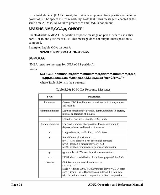
Page 78
the t the
er s
In decimal almanac (DAL) format, the + sign is suppressed for a positive value inpower of E. The spaces are for readability. Note that if this message is enabled asame time ALM is, ALM takes precedence and DAL is not output.
$PASHS,NME,GGA,x, ON/OFF
Enable/disable NMEA GPS position response message on port x, where x is eithport A or B, and y is ON or OFF. This message does not output unless position icomputed.
Example: Enable GGA on port A
$PASHS,NME,GGA,A,ON<Enter>
$GPGGA
NMEA response message for GGA (GPS position):
Format:
$GPGGA,hhmmss.ss,ddmm. mmmmm,s,dddmm.mmmmm,s,n,qq,pp.p,saaaaa.aa,M,±xxxx.xx,M,sss,aaaa *cc<CR><LF>
where Table 5.20 lists the structure:
Table 5.20: $GPGGA Response Messages
Field Description
hhmmss.ss Current UTC time, hhmmss, of position fix in hours, minutes and seconds.
ddmm.mmmmmm Latitude component of position, ddmm.mmmmm, in degrees, minutes and fraction of minutes.
s Latitude sector, s = N - North, s = S - South.
dddmm.mmmmm Longitude component of position, dddmm.mmmmm, in degrees, minutes and fraction of minutes.
s Longitude sector, s = E - East, s = W - West.
n Raw/differential position, nn = 1 - Raw; position is not differential correctedn = 2 - position is deferentially corrected. n = 9 - position computed using almanac information
qq qq = number of SVs used in position computation.
pp.p HDOP - horizontal dilution of precision, pp.p = 00.0 to 99.9.
saaaa.aa GPS Sensor-computed altitude, saaaaas = "+" or "-"aaaaa = Altitude 00000 to 30000 meters above WGS-84 refer-ence ellipsoid. For 2-D position computation this item con-tains the altitude used to compute the position computation.
ADU2 Operation and Reference Manual
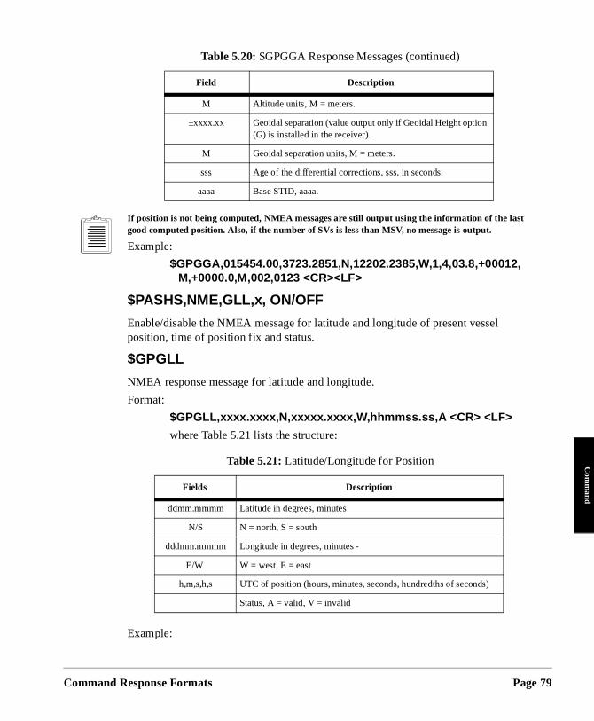
Command
Com
mand
If position is not being computed, NMEA messages are still output using the information of the last good computed position. Also, if the number of SVs is less than MSV, no message is output.
Example:
$GPGGA,015454.00,3723.2851,N,12202.2385,W,1,4,03.8,+00012,M,+0000.0,M,002,0123 <CR><LF>
$PASHS,NME,GLL,x, ON/OFF
Enable/disable the NMEA message for latitude and longitude of present vessel position, time of position fix and status.
$GPGLL
NMEA response message for latitude and longitude.
Format:
$GPGLL,xxxx.xxxx,N,xxxxx.xxxx,W,hhmmss.ss,A <CR> <LF>
where Table 5.21 lists the structure:
Example:
M Altitude units, M = meters.
±xxxx.xx Geoidal separation (value output only if Geoidal Height option (G) is installed in the receiver).
M Geoidal separation units, M = meters.
sss Age of the differential corrections, sss, in seconds.
aaaa Base STID, aaaa.
Table 5.21: Latitude/Longitude for Position
Fields Description
ddmm.mmmm Latitude in degrees, minutes
N/S N = north, S = south
dddmm.mmmm Longitude in degrees, minutes -
E/W W = west, E = east
h,m,s,h,s UTC of position (hours, minutes, seconds, hundredths of seconds)
Status, A = valid, V = invalid
Table 5.20: $GPGGA Response Messages (continued)
Field Description
Response Formats Page 79
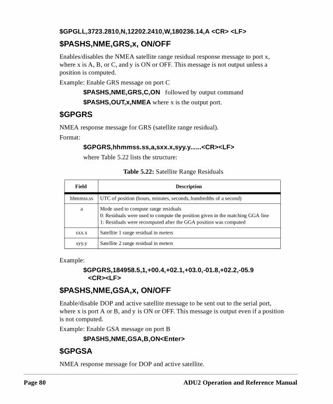
Page 80
,
t, ition
$GPGLL,3723.2810,N,12202.2410,W,180236.14,A <CR> <LF>
$PASHS,NME,GRS,x, ON/OFF
Enables/disables the NMEA satellite range residual response message to port xwhere x is A, B, or C, and y is ON or OFF. This message is not output unless a position is computed.
Example: Enable GRS message on port C
$PASHS,NME,GRS,C,ON followed by output command
$PASHS,OUT,x,NMEA where x is the output port.
$GPGRS
NMEA response message for GRS (satellite range residual).
Format:
$GPGRS,hhmmss.ss,a,sxx.x,syy.y......<CR><LF>
where Table 5.22 lists the structure:
Example:
$GPGRS,184958.5,1,+00.4,+02.1,+03.0,-01.8,+02.2,-05.9 <CR><LF>
$PASHS,NME,GSA,x, ON/OFF
Enable/disable DOP and active satellite message to be sent out to the serial porwhere x is port A or B, and y is ON or OFF. This message is output even if a posis not computed.
Example: Enable GSA message on port B
$PASHS,NME,GSA,B,ON<Enter>
$GPGSA
NMEA response message for DOP and active satellite.
Table 5.22: Satellite Range Residuals
Field Description
hhmmss.ss UTC of position (hours, minutes, seconds, hundredths of a second)
a Mode used to compute range residuals 0: Residuals were used to compute the position given in the matching GGA line 1: Residuals were recomputed after the GGA position was computed
sxx.x Satellite 1 range residual in meters
syy.y Satellite 2 range residual in meters
ADU2 Operation and Reference Manual
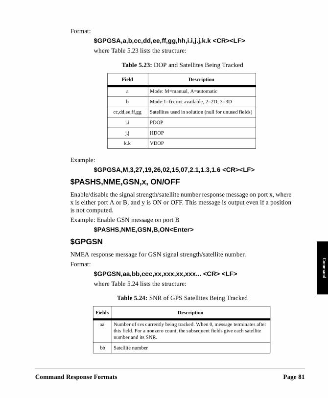
Command
Com
mand
where ition
Format:
$GPGSA,a,b,cc,dd,ee,ff,gg,hh,i.i,j.j,k.k <CR><LF>
where Table 5.23 lists the structure:
Example:
$GPGSA,M,3,27,19,26,02,15,07,2.1,1.3,1.6 <CR><LF>
$PASHS,NME,GSN,x, ON/OFF
Enable/disable the signal strength/satellite number response message on port x,x is either port A or B, and y is ON or OFF. This message is output even if a posis not computed.
Example: Enable GSN message on port B
$PASHS,NME,GSN,B,ON<Enter>
$GPGSN
NMEA response message for GSN signal strength/satellite number.
Format:
$GPGSN,aa,bb,ccc,xx,xxx,xx,xxx... <CR> <LF>
where Table 5.24 lists the structure:
Table 5.23: DOP and Satellites Being Tracked
Field Description
a Mode: M=manual, A=automatic
b Mode:1=fix not available, 2=2D, 3=3D
cc,dd,ee,ff,gg Satellites used in solution (null for unused fields)
i.i PDOP
j.j HDOP
k.k VDOP
Table 5.24: SNR of GPS Satellites Being Tracked
Fields Description
aa Number of svs currently being tracked. When 0, message terminates after this field. For a nonzero count, the subsequent fields give each satellite number and its SNR.
bb Satellite number
Response Formats Page 81
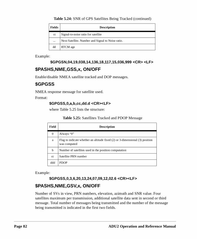
Page 82
hird essage
Example:
$GPGSN,04,19,038,14,136,18,117,15,036,999 <CR> <LF>
$PASHS,NME,GSS,x, ON/OFF
Enable/disable NMEA satellite tracked and DOP messages.
$GPGSS
NMEA response message for satellite used.
Format:
$GPGSS,0,a,b,cc,dd.d <CR><LF>
where Table 5.25 lists the structure:
Example:
$GPGSS,0,3,6,20,13,24,07,09,12,02.6 <CR><LF>
$PASHS,NME,GSV,x, ON/OFF
Number of SVs in view, PRN numbers, elevation, azimuth and SNR value. Four satellites maximum per transmission, additional satellite data sent in second or tmessage. Total number of messages being transmitted and the number of the mbeing transmitted is indicated in the first two fields.
cc Signal-to-noise ratio for satellite
... Next Satellite. Number and Signal to Noise ratio.
dd RTCM age
Table 5.25: Satellites Tracked and PDOP Message
Field Description
0 Always “0”
a Flag to indicate whether an altitude fixed (2) or 3-dimensional (3) position was computed
b Number of satellites used in the position computation
cc Satellite PRN number
ddd PDOP
Table 5.24: SNR of GPS Satellites Being Tracked (continued)
Fields Description
ADU2 Operation and Reference Manual
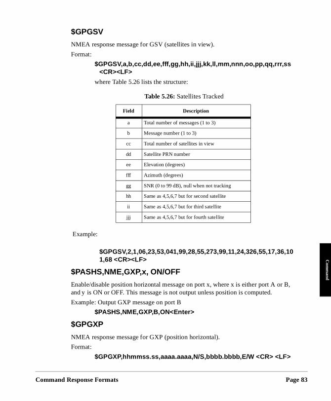
Command
Com
mand
B,
$GPGSV
NMEA response message for GSV (satellites in view).
Format:
$GPGSV,a,b,cc,dd,ee,fff,gg,hh,ii,jjj,kk,ll,mm,nnn,oo,pp,qq,rrr,ss <CR><LF>
where Table 5.26 lists the structure:
Example:
$GPGSV,2,1,06,23,53,041,99,28,55,273,99,11,24,326,55,17,36,101,68 <CR><LF>
$PASHS,NME,GXP,x, ON/OFF
Enable/disable position horizontal message on port x, where x is either port A orand y is ON or OFF. This message is not output unless position is computed.
Example: Output GXP message on port B
$PASHS,NME,GXP,B,ON<Enter>
$GPGXP
NMEA response message for GXP (position horizontal).
Format:
$GPGXP,hhmmss.ss,aaaa.aaaa,N/S,bbbb.bbbb,E/W <CR> <LF>
Table 5.26: Satellites Tracked
Field Description
a Total number of messages (1 to 3)
b Message number (1 to 3)
cc Total number of satellites in view
dd Satellite PRN number
ee Elevation (degrees)
fff Azimuth (degrees)
gg SNR (0 to 99 dB), null when not tracking
hh Same as 4,5,6,7 but for second satellite
ii Same as 4,5,6,7 but for third satellite
jjj Same as 4,5,6,7 but for fourth satellite
Response Formats Page 83
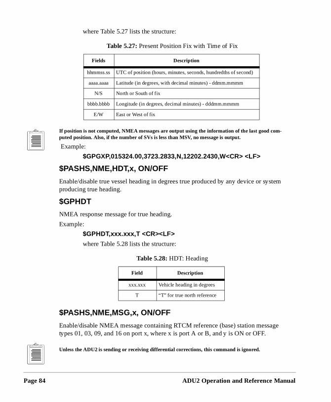
Page 84
stem
age
where Table 5.27 lists the structure:
If position is not computed, NMEA messages are output using the information of the last good com-puted position. Also, if the number of SVs is less than MSV, no message is output.
Example:
$GPGXP,015324.00,3723.2833,N,12202.2430,W<CR> <LF>
$PASHS,NME,HDT,x, ON/OFF
Enable/disable true vessel heading in degrees true produced by any device or syproducing true heading.
$GPHDT
NMEA response message for true heading.
Example:
$GPHDT,xxx.xxx,T <CR><LF>
where Table 5.28 lists the structure:
$PASHS,NME,MSG,x, ON/OFF
Enable/disable NMEA message containing RTCM reference (base) station messtypes 01, 03, 09, and 16 on port x, where x is port A or B, and y is ON or OFF.
Unless the ADU2 is sending or receiving differential corrections, this command is ignored.
Table 5.27: Present Position Fix with Time of Fix
Fields Description
hhmmss.ss UTC of position (hours, minutes, seconds, hundredths of second)
aaaa.aaaa Latitude (in degrees, with decimal minutes) - ddmm.mmmm
N/S North or South of fix
bbbb.bbbb Longitude (in degrees, decimal minutes) - dddmm.mmmm
E/W East or West of fix
Table 5.28: HDT: Heading
Field Description
xxx.xxx Vehicle heading in degrees
T “T” for true north reference
ADU2 Operation and Reference Manual
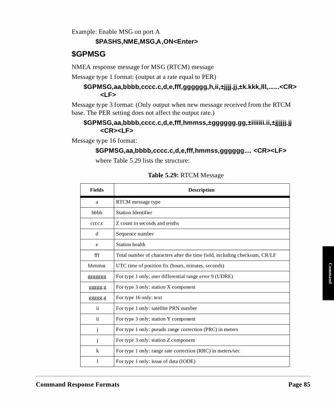
Command
Com
mand
M
Example: Enable MSG on port A
$PASHS,NME,MSG,A,ON<Enter>
$GPMSG
NMEA response message for MSG (RTCM) message
Message type 1 format: (output at a rate equal to PER)
$GPMSG,aa,bbbb,cccc.c,d,e,fff,gggggg,h,ii,±jjjj.jj ,±k.kkk,lll,......<CR><LF>
Message type 3 format: (Only output when new message received from the RTCbase. The PER setting does not affect the output rate.)
$GPMSG,aa,bbbb,cccc.c,d,e,fff,hmmss,±gggggg.gg,±iiiiiii.ii,±jjjjjj.jj <CR><LF>
Message type 16 format:
$GPMSG,aa,bbbb,cccc.c,d,e,fff,hmmss,gggggg.... <CR><LF>
where Table 5.29 lists the structure:
Table 5.29: RTCM Message
Fields Description
a RTCM message type
bbbb Station Identifier
cccc.c Z count in seconds and tenths
d Sequence number
e Station health
fff Total number of characters after the time field, including checksum, CR/LF
hhmmss UTC time of position fix (hours, minutes, seconds)
ggggggg For type 1 only: user differential range error 9 (UDRE)
ggggg.g For type 3 only: station X component
ggggg.g For type 16 only: text
ii For type 1 only: satellite PRN number
ii For type 3 only: station Y component
j For type 1 only: pseudo range correction (PRC) in meters
j For type 3 only: station Z component
k For type 1 only: range rate correction (RRC) in meters/sec
l For type 1 only: issue of data (IODE)
Response Formats Page 85
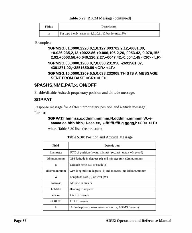
Page 86
Examples:
$GPMSG,01,0000,2220.0,1,0,127,003702,2,12,-0081.30, +0.026,235,2,13,+0022.86,+0.006,106,2,26,-0053.42,-0.070,155, 2,02,+0003.56,+0.040,120,2,27,+0047.42,-0.004,145 <CR> <LF>
$GPMSG,03,0000,1200.0,7,0,038,231958,-2691561.37, 4301271.02,+3851650.89 <CR> <LF>
$GPMSG,16,0000,1209.6,5,0,038,232008,THIS IS A MESSAGE SENT FROM BASE <CR> <LF>
$PASHS,NME,PAT,x, ON/OFF
Enable/disable Ashtech proprietary position and altitude message.
$GPPAT
Response message for Ashtech proprietary position and altitude message.
Format:
$GPPAT,hhmmss.s,ddmm.mmmm,N,dddmm.mmmm,W,+/-aaaaa.aa,bbb.bbb,+/-eee.ee,+/-fff.fff.ffff,g.gggg,h<CR> <LF>
where Table 5.30 lists the structure:
m For type 1 only: same as 8,9,10,11,12 but for next SVs
Table 5.30: Position and Attitude Message
Field Description
hhmmss.s UTC of position (hours, minutes, seconds, tenths of second)
ddmm.mmmm GPS latitude in degrees (d) and minutes (m): ddmm.mmmm
N Latitude north (N) or south (S)
dddmm.mmmm GPS longitude in degrees (d) and minutes (m) dddmm.mmmm
W Longitude east (E) or west (W)
aaaaa.aa Altitude in meters
bbb.bbb Heading in degrees
eee.ee Pitch in degrees
fff.fff.ffff Roll in degrees
h Attitude phase measurement rms error, MRMS (meters)
Table 5.29: RTCM Message (continued)
Fields Description
ADU2 Operation and Reference Manual
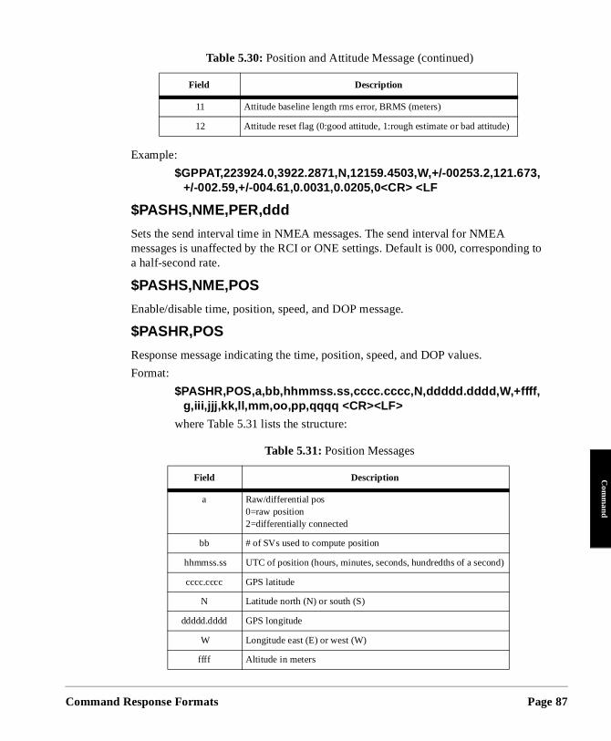
Command
Com
mand
ng to
Example:
$GPPAT,223924.0,3922.2871,N,12159.4503,W,+/-00253.2,121.673, +/-002.59,+/-004.61,0.0031,0.0205,0<CR> <LF
$PASHS,NME,PER,ddd
Sets the send interval time in NMEA messages. The send interval for NMEA messages is unaffected by the RCI or ONE settings. Default is 000, correspondia half-second rate.
$PASHS,NME,POS
Enable/disable time, position, speed, and DOP message.
$PASHR,POS
Response message indicating the time, position, speed, and DOP values.
Format:
$PASHR,POS,a,bb,hhmmss.ss,cccc.cccc,N,ddddd.dddd,W,+ffff,g,iii,jjj,kk,ll,mm,oo,pp,qqqq <CR><LF>
where Table 5.31 lists the structure:
11 Attitude baseline length rms error, BRMS (meters)
12 Attitude reset flag (0:good attitude, 1:rough estimate or bad attitude)
Table 5.31: Position Messages
Field Description
a Raw/differential pos0=raw position2=differentially connected
bb # of SVs used to compute position
hhmmss.ss UTC of position (hours, minutes, seconds, hundredths of a second)
cccc.cccc GPS latitude
N Latitude north (N) or south (S)
ddddd.dddd GPS longitude
W Longitude east (E) or west (W)
ffff Altitude in meters
Table 5.30: Position and Attitude Message (continued)
Field Description
Response Formats Page 87
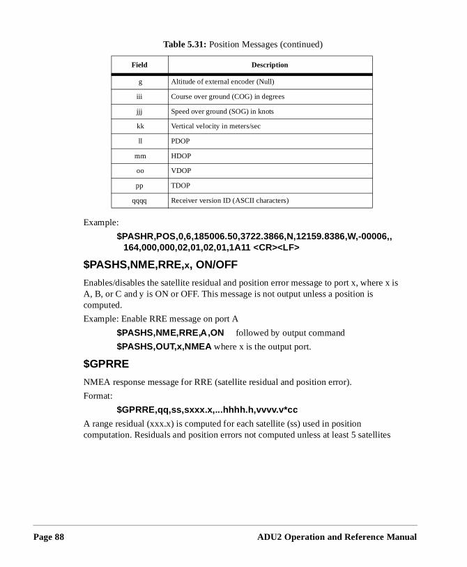
Page 88
re x is
ites
Example:
$PASHR,POS,0,6,185006.50,3722.3866,N,12159.8386,W,-00006,, 164,000,000,02,01,02,01,1A11 <CR><LF>
$PASHS,NME,RRE,x, ON/OFF
Enables/disables the satellite residual and position error message to port x, wheA, B, or C and y is ON or OFF. This message is not output unless a position is computed.
Example: Enable RRE message on port A
$PASHS,NME,RRE,A,ON followed by output command
$PASHS,OUT,x,NMEA where x is the output port.
$GPRRE
NMEA response message for RRE (satellite residual and position error).
Format:
$GPRRE,qq,ss,sxxx.x,...hhhh.h,vvvv.v*cc
A range residual (xxx.x) is computed for each satellite (ss) used in position computation. Residuals and position errors not computed unless at least 5 satell
g Altitude of external encoder (Null)
iii Course over ground (COG) in degrees
jjj Speed over ground (SOG) in knots
kk Vertical velocity in meters/sec
ll PDOP
mm HDOP
oo VDOP
pp TDOP
qqqq Receiver version ID (ASCII characters)
Table 5.31: Position Messages (continued)
Field Description
ADU2 Operation and Reference Manual
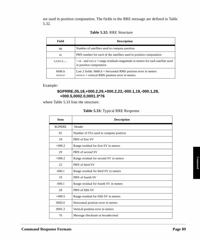
Command
Com
mand
Table
are used in position computation. The fields in the RRE message are defined in 5.32.Example:
$GPRRE,05,18,+000.2,29,+000.2,22,-000.1,19,-000.1,28, +000.5,0002.0,0001.3*76
where Table 5.33 lists the structure:
Table 5.32: RRE Structure
Field Description
qq Number of satellites used to compute position
ss PRN number for each of the satellites used in position computation
s,xxx.x..... + or - and xxx.x = range residuals magnitude in meters for each satellite used in position computation
hhhh.hvvvv.v
Last 2 fields: hhhh.h = horizontal RMS position error in metersvvvv.v = vertical RMS position error in meters
Table 5.33: Typical RRE Response
Item Description
$GPRRE Header
05 Number of SVs used to compute position
18 PRN of first SV
+000.2 Range residual for first SV in meters
29 PRN of second SV
+000.2 Range residual for second SV in meters
22 PRN of third SV
-000.1 Range residual for third SV in meters
19 PRN of fourth SV
-000.1 Range residual for fourth SV in meters
28 PRN of fifth SV
+000.5 Range residual for fifth SV in meters
0002.0 Horizontal position error in meters
0001.3 Vertical position error in meters
76 Message checksum in hexadecimal
Response Formats Page 89
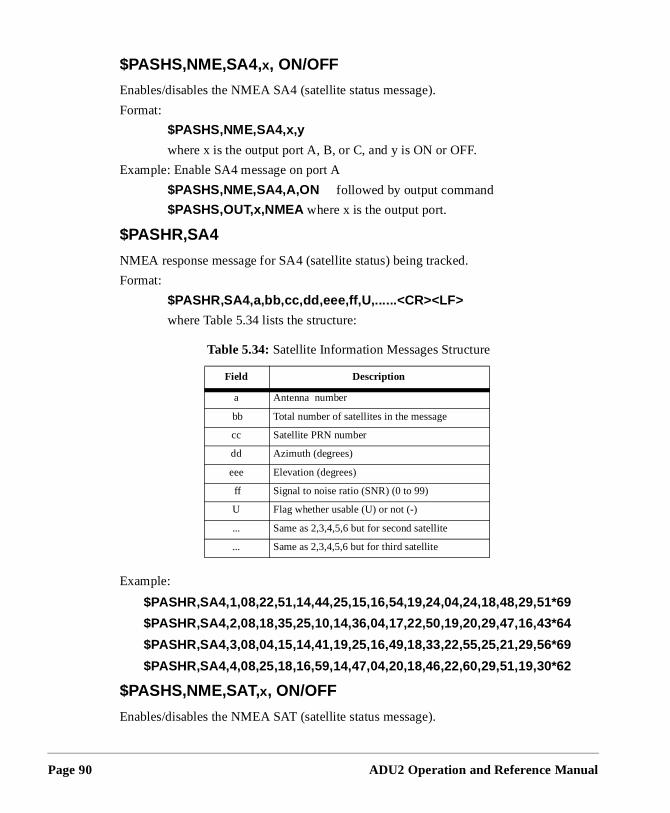
Page 90
$PASHS,NME,SA4,x, ON/OFF
Enables/disables the NMEA SA4 (satellite status message).
Format:
$PASHS,NME,SA4,x,y
where x is the output port A, B, or C, and y is ON or OFF.
Example: Enable SA4 message on port A
$PASHS,NME,SA4,A,ON followed by output command
$PASHS,OUT,x,NMEA where x is the output port.
$PASHR,SA4
NMEA response message for SA4 (satellite status) being tracked.
Format:
$PASHR,SA4,a,bb,cc,dd,eee,ff,U,......<CR><LF>
where Table 5.34 lists the structure:
Example:
$PASHR,SA4,1,08,22,51,14,44,25,15,16,54,19,24,04,24,18,48,29,51*69
$PASHR,SA4,2,08,18,35,25,10,14,36,04,17,22,50,19,20,29,47,16,43*64
$PASHR,SA4,3,08,04,15,14,41,19,25,16,49,18,33,22,55,25,21,29,56*69
$PASHR,SA4,4,08,25,18,16,59,14,47,04,20,18,46,22,60,29,51,19,30*62
$PASHS,NME,SAT,x, ON/OFF
Enables/disables the NMEA SAT (satellite status message).
Table 5.34: Satellite Information Messages Structure
Field Description
a Antenna number
bb Total number of satellites in the message
cc Satellite PRN number
dd Azimuth (degrees)
eee Elevation (degrees)
ff Signal to noise ratio (SNR) (0 to 99)
U Flag whether usable (U) or not (-)
... Same as 2,3,4,5,6 but for second satellite
... Same as 2,3,4,5,6 but for third satellite
ADU2 Operation and Reference Manual
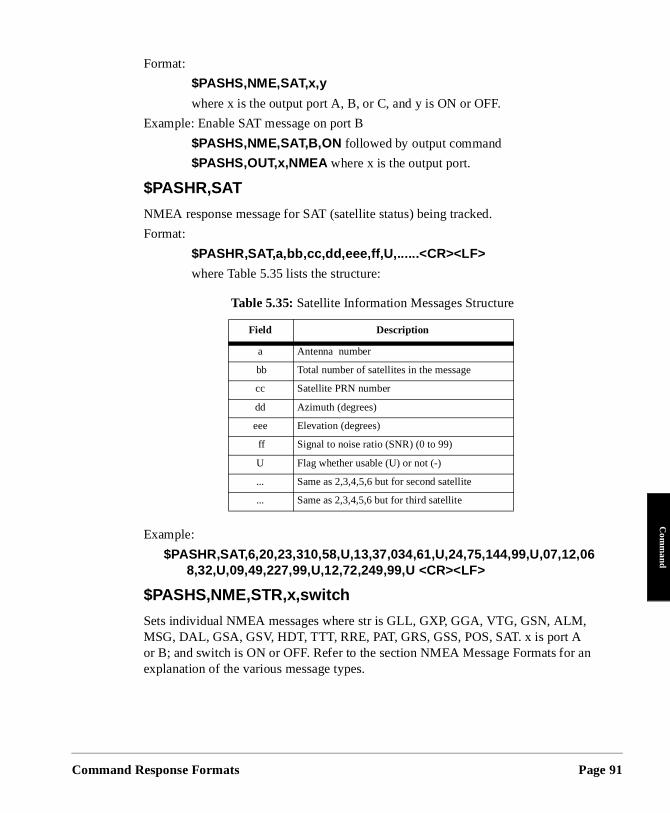
Command
Com
mand
,
an
Format:
$PASHS,NME,SAT,x,y
where x is the output port A, B, or C, and y is ON or OFF.
Example: Enable SAT message on port B
$PASHS,NME,SAT,B,ON followed by output command
$PASHS,OUT,x,NMEA where x is the output port.
$PASHR,SAT
NMEA response message for SAT (satellite status) being tracked.
Format:
$PASHR,SAT,a,bb,cc,dd,eee,ff,U,......<CR><LF>
where Table 5.35 lists the structure:
Example:
$PASHR,SAT,6,20,23,310,58,U,13,37,034,61,U,24,75,144,99,U,07,12,068,32,U,09,49,227,99,U,12,72,249,99,U <CR><LF>
$PASHS,NME,STR,x,switch
Sets individual NMEA messages where str is GLL, GXP, GGA, VTG, GSN, ALMMSG, DAL, GSA, GSV, HDT, TTT, RRE, PAT, GRS, GSS, POS, SAT. x is port A or B; and switch is ON or OFF. Refer to the section NMEA Message Formats forexplanation of the various message types.
Table 5.35: Satellite Information Messages Structure
Field Description
a Antenna number
bb Total number of satellites in the message
cc Satellite PRN number
dd Azimuth (degrees)
eee Elevation (degrees)
ff Signal to noise ratio (SNR) (0 to 99)
U Flag whether usable (U) or not (-)
... Same as 2,3,4,5,6 but for second satellite
... Same as 2,3,4,5,6 but for third satellite
Response Formats Page 91
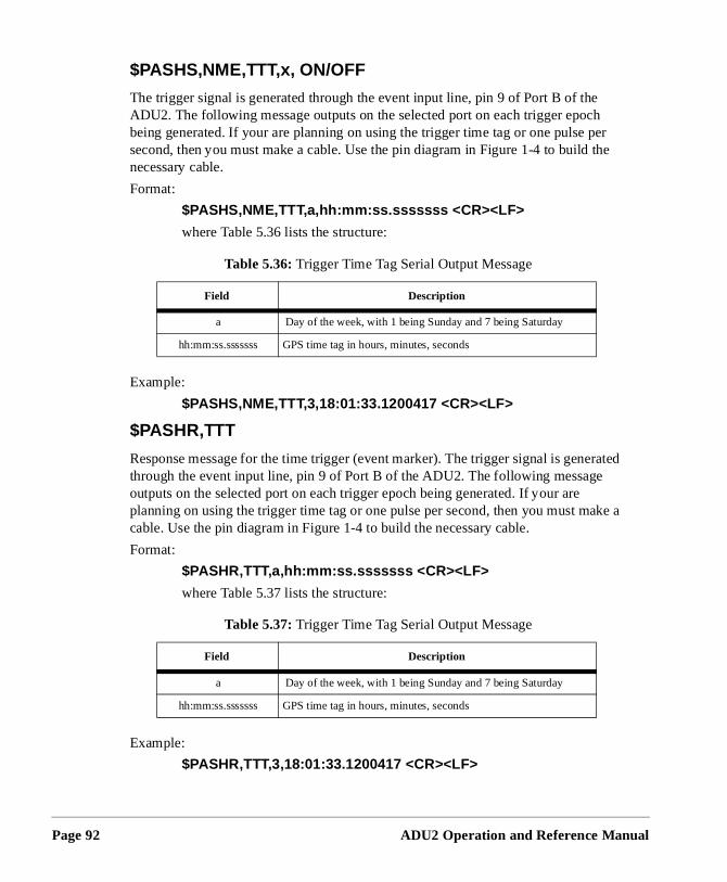
Page 92
h er the
rated
ake a
$PASHS,NME,TTT,x, ON/OFF
The trigger signal is generated through the event input line, pin 9 of Port B of theADU2. The following message outputs on the selected port on each trigger epocbeing generated. If your are planning on using the trigger time tag or one pulse psecond, then you must make a cable. Use the pin diagram in Figure 1-4 to build necessary cable.
Format:
$PASHS,NME,TTT,a,hh:mm:ss.sssssss <CR><LF>
where Table 5.36 lists the structure:
Example:
$PASHS,NME,TTT,3,18:01:33.1200417 <CR><LF>
$PASHR,TTT
Response message for the time trigger (event marker). The trigger signal is genethrough the event input line, pin 9 of Port B of the ADU2. The following messageoutputs on the selected port on each trigger epoch being generated. If your are planning on using the trigger time tag or one pulse per second, then you must mcable. Use the pin diagram in Figure 1-4 to build the necessary cable.
Format:
$PASHR,TTT,a,hh:mm:ss.sssssss <CR><LF>
where Table 5.37 lists the structure:
Example:
$PASHR,TTT,3,18:01:33.1200417 <CR><LF>
Table 5.36: Trigger Time Tag Serial Output Message
Field Description
a Day of the week, with 1 being Sunday and 7 being Saturday
hh:mm:ss.sssssss GPS time tag in hours, minutes, seconds
Table 5.37: Trigger Time Tag Serial Output Message
Field Description
a Day of the week, with 1 being Sunday and 7 being Saturday
hh:mm:ss.sssssss GPS time tag in hours, minutes, seconds
ADU2 Operation and Reference Manual
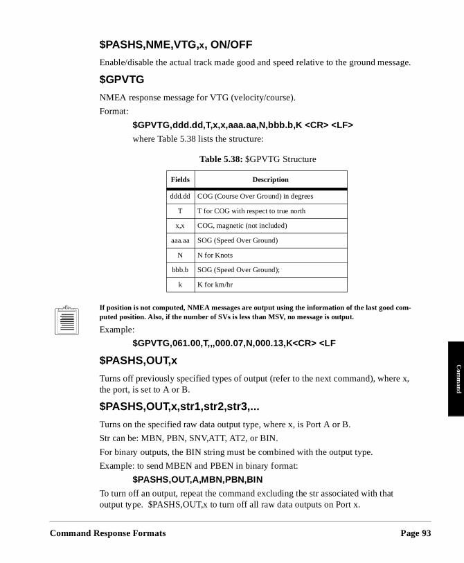
Command
Com
mand
x,
$PASHS,NME,VTG,x, ON/OFF
Enable/disable the actual track made good and speed relative to the ground message.
$GPVTG
NMEA response message for VTG (velocity/course).
Format:
$GPVTG,ddd.dd,T,x,x,aaa.aa,N,bbb.b,K <CR> <LF>
where Table 5.38 lists the structure:
If position is not computed, NMEA messages are output using the information of the last good com-puted position. Also, if the number of SVs is less than MSV, no message is output.
Example:
$GPVTG,061.00,T,,,000.07,N,000.13,K<CR> <LF
$PASHS,OUT,x
Turns off previously specified types of output (refer to the next command), wherethe port, is set to A or B.
$PASHS,OUT,x,str1,str2,str3,...
Turns on the specified raw data output type, where x, is Port A or B.
Str can be: MBN, PBN, SNV,ATT, AT2, or BIN.
For binary outputs, the BIN string must be combined with the output type.
Example: to send MBEN and PBEN in binary format:
$PASHS,OUT,A,MBN,PBN,BIN
To turn off an output, repeat the command excluding the str associated with thatoutput type. $PASHS,OUT,x to turn off all raw data outputs on Port x.
Table 5.38: $GPVTG Structure
Fields Description
ddd.dd COG (Course Over Ground) in degrees
T T for COG with respect to true north
x,x COG, magnetic (not included)
aaa.aa SOG (Speed Over Ground)
N N for Knots
bbb.b SOG (Speed Over Ground);
k K for km/hr
Response Formats Page 93
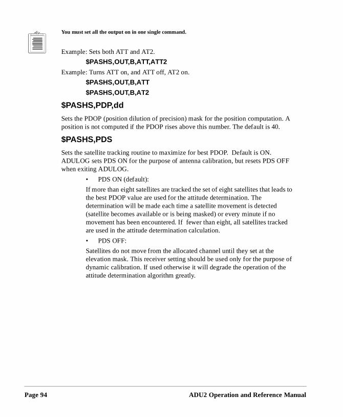
Page 94
. A
FF
s to
ed
e of
You must set all the output on in one single command.
Example: Sets both ATT and AT2.
$PASHS,OUT,B,ATT,ATT2
Example: Turns ATT on, and ATT off, AT2 on.
$PASHS,OUT,B,ATT
$PASHS,OUT,B,AT2
$PASHS,PDP,dd
Sets the PDOP (position dilution of precision) mask for the position computationposition is not computed if the PDOP rises above this number. The default is 40.
$PASHS,PDS
Sets the satellite tracking routine to maximize for best PDOP. Default is ON. ADULOG sets PDS ON for the purpose of antenna calibration, but resets PDS Owhen exiting ADULOG.
• PDS ON (default):
If more than eight satellites are tracked the set of eight satellites that leadthe best PDOP value are used for the attitude determination. The determination will be made each time a satellite movement is detected (satellite becomes available or is being masked) or every minute if no movement has been encountered. If fewer than eight, all satellites trackare used in the attitude determination calculation.
• PDS OFF:
Satellites do not move from the allocated channel until they set at the elevation mask. This receiver setting should be used only for the purposdynamic calibration. If used otherwise it will degrade the operation of theattitude determination algorithm greatly.
ADU2 Operation and Reference Manual
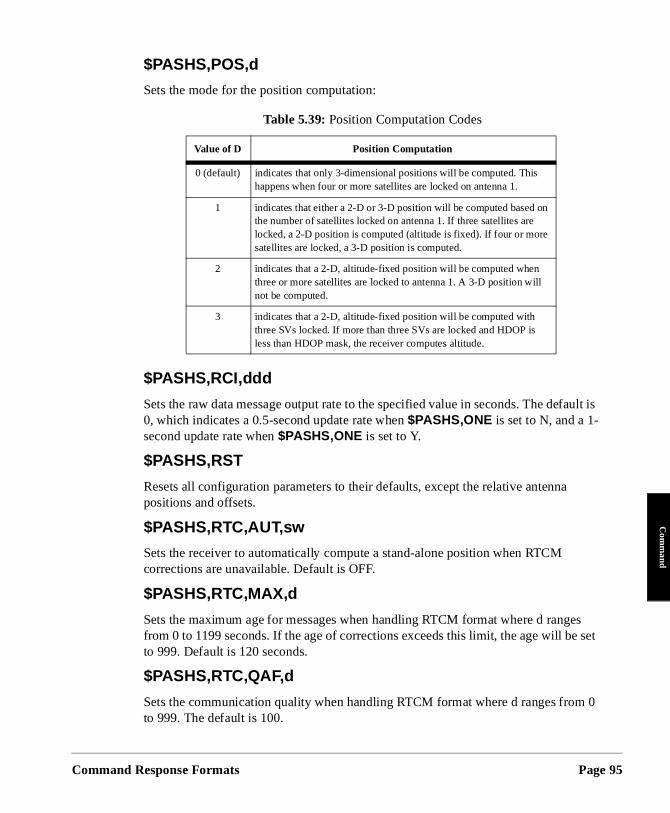
Command
Com
mand
fault is
es e set
m 0
$PASHS,POS,d
Sets the mode for the position computation:
$PASHS,RCI,ddd
Sets the raw data message output rate to the specified value in seconds. The de0, which indicates a 0.5-second update rate when $PASHS,ONE is set to N, and a 1-second update rate when $PASHS,ONE is set to Y.
$PASHS,RST
Resets all configuration parameters to their defaults, except the relative antennapositions and offsets.
$PASHS,RTC,AUT,sw
Sets the receiver to automatically compute a stand-alone position when RTCM corrections are unavailable. Default is OFF.
$PASHS,RTC,MAX,d
Sets the maximum age for messages when handling RTCM format where d rangfrom 0 to 1199 seconds. If the age of corrections exceeds this limit, the age will bto 999. Default is 120 seconds.
$PASHS,RTC,QAF,d
Sets the communication quality when handling RTCM format where d ranges froto 999. The default is 100.
Table 5.39: Position Computation Codes
Value of D Position Computation
0 (default) indicates that only 3-dimensional positions will be computed. This happens when four or more satellites are locked on antenna 1.
1 indicates that either a 2-D or 3-D position will be computed based on the number of satellites locked on antenna 1. If three satellites are locked, a 2-D position is computed (altitude is fixed). If four or more satellites are locked, a 3-D position is computed.
2 indicates that a 2-D, altitude-fixed position will be computed when three or more satellites are locked to antenna 1. A 3-D position will not be computed.
3 indicates that a 2-D, altitude-fixed position will be computed with three SVs locked. If more than three SVs are locked and HDOP is less than HDOP mask, the receiver computes altitude.
Response Formats Page 95
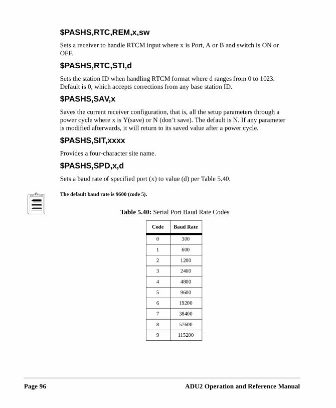
Page 96
r
h a ter
$PASHS,RTC,REM,x,sw
Sets a receiver to handle RTCM input where x is Port, A or B and switch is ON oOFF.
$PASHS,RTC,STI,d
Sets the station ID when handling RTCM format where d ranges from 0 to 1023.Default is 0, which accepts corrections from any base station ID.
$PASHS,SAV,x
Saves the current receiver configuration, that is, all the setup parameters througpower cycle where x is Y(save) or N (don’t save). The default is N. If any parameis modified afterwards, it will return to its saved value after a power cycle.
$PASHS,SIT,xxxx
Provides a four-character site name.
$PASHS,SPD,x,d
Sets a baud rate of specified port (x) to value (d) per Table 5.40.
The default baud rate is 9600 (code 5).
Table 5.40: Serial Port Baud Rate Codes
Code Baud Rate
0 300
1 600
2 1200
3 2400
4 4800
5 9600
6 19200
7 38400
8 57600
9 115200
ADU2 Operation and Reference Manual
Command
Com
mand
N to is
e
x is
$PASHS,SVS,xxxxxxxxxx
Enables or disables all 32 satellite PRN numbers at once by typing Y to enable ordisable a particular satellite (any character other than Y is interpreted as N). If thcommand is issued and is incomplete, all remaining satellites are disabled. The default is all satellites enabled. For example, the command $PASHS,SVS,YYYNYYY enables SV’s 1,2,3,5,6,7 and disables all the remainingSV’s (that is, 4,8,9,10,...32).
$PASHS,UNH,x
Uses unhealthy satellites in position computation when Y. Unhealthy satellites aralways used for attitude determination. The default is N.
$PASHS,USE,dd,x
Enables or disables satellite tracking where dd is the satellite PRN number and uppercase Y (enable) or N (disable). For example, to disable satellite 8, enter $PASHS,USE,08,N.
$PASHS,VDP,dd
Sets VDOP (vertical dilution of precision) mask for the position computation. A position is not computed if the VDOP rises above this number. The default is 4.
Response Formats Page 97

Page 98
ADU2 Operation and Reference Manual
6
TroubleshootingTroubleshooting
Troublesho
the
lve ted
The
ge-
ble
pin-the
.
This chapter contains information for troubleshooting problems with the operation of ADU2. It is divided into two sections depending on the type of problem:
• Installation and initialization problems. • Position and attitude measurement problems.
For each section, there is a list of potential problems and suggestions on how to resothem. Refer to Chapter 6 for an explanation of any of the commands that are suggesbelow.
Installation and Initialization Problems
No power at the receiver
• The DC power supply should provide 12 to 32 V at 2A. • The battery should be fully charged. • Check the results from the initialization self-test with the $PASHQ,TST
command.
No communication response from the receiver
• Connect the interface cable to a different port (A or B).• The baud rate of the PC communications program should match the ADU2.
ADU2 default rate 9600 baud, 8 data bits, 1 stop bit, no parity. • The commands being issued from the PC should be terminated with a carria
return and linefeed. • Turn the power to the receiver off and then on again.• If RTCM is enabled on a port, no other communication with that port is possi
until RTCM is disabled.• Make sure the interface cable is securely fastened to the ADU2 and the PC.• If the interface cable was not supplied by Ashtech, check the J1 connector’s
out diagram of the RS-232 ports with the cable you manufactured. (Refer to Overview.)
• Clear internal memory with the $PASHS,INI command. (You may need to toggle the power to the receiver after this command is issued.) An example session using the PCPLUS communications program is as follows:
Run PCPLUS and press <ALT-P> to configure the port properly to 9600 baud. Next, press <ALT-O> to enter the command mode. Type $PASHQ,PRT <Enter> to ask the receiver for its serial port configuration
oting Page 99
Page 100
s for
he
s al-
a ith
gree
nal
All letters must be capital and <Enter> is the enter key. <ENTER> should provide both a carriage-return <CR> and linefeed <LF>. These must be at the end of any command given to the ADU2. For the PCPLUS program, <CTRL-J> and <CTRL-M> may be used instead of the enter key to represent a carriage-return/linefeed. The ADU2 should respond to this command with $PASHR,PRT,A,5 indicating the use serial port A at 9600 baud (code 5).
Position and Attitude Measurement Problems
Receiver does not compute position
• Antenna 1 is used to compute position. Check the satellite tracking statuAntenna 1 with the command $PASHQ,STA . At least four satellites should be locked on Antenna 1.
• Check for satellites below the elevation mask angle (default is 10 ) with t$PASHQ,GSV or $PASHQ,SAT command.
• Check if PDOP is above the pdop mask (default is 40) with the $PASHQ,GSA command.
• Check for unhealthy satellites with the $PASHQ,SAT command. • Verify that the receiver is not locked-up and is currently tracking satellite
with the $PASHQ,STA command two or three times and see that the signto-noise ratios change for a locked satellite on a particular bank.
• Make sure signal-to-noise ratios (SNR) are strong enough. The SNR forparticular satellite should be about twice its elevation angle. Verify this wthe $PASHQ,SAT command. SNR values of 20 or greater are generallyusable. SNR values for higher elevation satellites range from 60 to 99.
Causes for Bad Antennas or Low SNRs
• Check for damaged coaxial cable, such as broken shielding, salt water intrusion between shielding and the conductor, poor connections at the terminations.
• Make sure antenna coaxial cables cross high voltage lines only at 90 deangles if possible.
• Check for condensation or saltwater (spray) intrusion inside the antennahousing.
• Check for bad LNA (preamp) in the antenna. In this case there is no sigat all.
ADU2 Operation and Reference Manual
Troublesho
Troubleshooting
re
hat ic
sely,
d each
e
ed
oise
the the
ber,
• Monitor SNRs from antenna to antenna to make sure that none are significantly lower than the others with the $PASHQ,STA command.
Receiver computes position but not attitude
• Verify cables are labeled properly and that: • Cable 1 is connected to antenna 1 and the Ant 1 port of the ADU2
receiver; • Cable 2 is connected to antenna 2 and the Ant 2 port of the ADU2
receiver;• Cable 3 is connected to antenna 3 and the Ant 3 port of the ADU2
receiver; • Cable 4 is connected to antenna 4 and the Ant 4 port of the ADU2
receiver.• Check that the relative antenna position vectors from the initial survey a
entered into the receiver properly and have the correct sign with the $PASHQ,3DF command.
• The initial relative antenna position survey is very important. Determine tthe survey provided valid results. (Refer to Chapter 4 for static or dynamsurvey.) Perform the survey more than once to validate the results. The static survey should provide nearly the same results every time. Convera dynamic survey does not provide exactly the same relative antenna position vectors each time (if the vehicle was indeed moving), but a goocheck is to make sure that the baseline lengths for each vector agree forsurvey.
• Verify that the antennas have not moved since the initial survey. The antennas should be mounted on a rigid platform. Very little relative movement between the antennas (less than 2 cm) can be tolerated.
• At least four satellites must be locked on all four antennas before attitudinformation can be computed. Verify this condition with the $PASHQ,STA command.
• For proper receiver performance, determine if all four antennas are lockevenly to the satellites with the $PASHQ,STA command . Verify that each satellite locked on all four antenna banks has about the same signal-to-n(SNR) ratio (max difference of ten counts).
• The vehicle may be tilted (pitch or roll) more than five degrees, which is default maximum angle around the horizon (+ and -) that the search for initial ambiguities takes place. If the vehicle tilts more than five degrees,increase this maximum search angle with the $PASHS,3DF,ANG,dd comand where dd can be a maximum of 90 degrees. The larger this num
oting Page 101
Page 102
C) d in ,
e
ier
], y
rch.
(the
s
be
ult 5
the longer it takes to determine the initial ambiguities for the attitude solution.
• The limits for the attitude measurement noise errors (BRMS, MRMS, CYmay have been exceeded. This happens when the antennas are installehigh-multipath environments (that is, antennas are located near metallicsignal-reflecting objects, see Appendix A). Check this as follows: • The default maximum BRMS (baseline rms) error is 3.5 cm. Try to
increase this by small steps (1 cm) with the $PASHS,3DF,MXB,0.060 command. Do not exceed 8 cm.
• The default maximum MRMS (measurement rms) error is 5 mm. Generally, a good attitude solution should always have an error less than this. It may be necessary for very noisy environments to set this valuslightly higher with the $PASHS,3DF,MXM,0.006 command.
• The default maximum phase cycle error is 15% of a cycle (1 L1 carrcycle = 19 cm). Try to increase this to 20% with the $PASHS,3DF,CYC,0.20 command.
Increase the BRMS and MRMS in small increments only.
• Before precise attitude information is given, the double-difference carrier phase ambiguities must be resolved. (Refer to References [1[2], and [3] in Appendix C). The search for the initial ambiguities mabe unsuccessful. The receiver keeps trying to determine these ambiguities until a solution is found. When the antenna separation isgreater than three meters, Kalman filters help with the ambiguity seaIf noisy, or bad, satellite measurement data was received by the ADU2, the Kalman filters may get “lost”. Reset the attitude’s Kalman filters with the $PASHS,3DF,RST command.
Noisy attitude data
• Check the attitude reset flag with the $PASHQ,ATT command. It should be “0” for precise attitude (carrier phase ambiguities are resolved). A “1” indicates that the attitude is a code phase estimate ambiguities have not yet been resolved).
• Check the attitude’s BRMS (baseline rms error), which should be lesthan 4 cm when an attitude solution is found with the $PASHQ,ATT command.
• Check the attitude’s MRMS (measurement rms error), which shouldless than 5 mm when an attitude solution is found with the $PASHQ,ATT command.
• Check the mask angle. Ashtech recommends that you keep the defasatellite elevation mask angle of 10 degrees (or even increase it to 1
ADU2 Operation and Reference Manual
Troublesho
Troubleshooting
rby
for
e
e nd roll set
e et r onds.
rrors h.
ally
e
l as d
degrees) since satellites at lower elevations have a high level of multipath on their signals due to reflections from the ground and neametal objects. Multipath is a major error source affecting attitude accuracy and reliability (See Appendix A).
• Check the PDOP computed by the receiver. It should be less than 6“clean” attitude data. The attitude data becomes very noisy and the solution may even be lost when PDOP rises above 6. A high PDOPcauses the BRMS error go above 4 cm. Increase the maximum allowable value of BRMSwith the $PASHS,3DF,MXB,d.ddd command.
Notes on Attitude Data
Antenna Separations
For antenna separations less than three meters, “999” appears for heading in thattitude output message ($PASHR,ATT,...) when the receiver is searching for the ambiguities, or when a valid solution has not been found. When the baselines argreater than three meters, a code phase estimate of heading appears and pitch aare exactly “0.00”. When either of these situations exist, the attitude reset flag isto “1” in the attitude output message (a “0” indicates a good attitude solution).
If the antenna separations are less than three meters, it should require only a fewseconds resolve the initial ambiguities and provide attitude information. When thantenna separations are greater than three meters and the Kalman filters are res($PASHS,3DF,RST), the receiver first smooths the satellite measurement data foten seconds before beginning the ambiguity search, which takes a few more sec
Attitude Quality Indicators
To assure a good attitude solution has been computed, the MRMS and BRMS eare used as quality indicators and are checked against maximums at every epoc
An incorrect attitude solution causes both the MRMS and BRMS errors to continugrow larger. The rate at which these errors grow depends on the relative motion between the vehicle and satellites. The higher the vehicle dynamics, the faster therror growth rate of a false solution.
Also, as Position Dilution of Precision (PDOP) becomes higher, the BRMS error grows as well. Typically, GPS provides good attitude information as long as PDOP is below 6, which is approximately 95% of the time with the full 24-satellite constellation, worldwide.
Multipath significantly affects the computed BRMS error, causing it to rise and falthe antennas receive "constructive" and "destructive" interference. The period an
oting Page 103
Page 104
hile
e ). r
amplitude of the multipath oscillations varies significantly depending on vehicle dynamics and environment. Static vehicles are the most affected by multipath wdynamic vehicles' multipath errors tend to average out.
The maximum limit for the BRMS error is set to 3.5 centimeters. This limit may bincreased for vehicles in high multipath environments that is, 6-8 centimeter limitThe maximum limit for the MRMS error is 5 millimeters and may be increased fohigh dynamic vehicles (that is, 6-7 millimeter limit).
ADU2 Operation and Reference Manual
7
ADU
L
ADULOG
OG
ADULOG
eal-
e d can
uded e
clude
r,
ADULOG , provided with the ADU2 receiver software, logs data from the receiver in rtime and saves the data in three files: b-file, e-file and a-file. The B-file contains raw measurements. The E-file contains ephemerides from all tracked satellites. The E-filcontains computed attitude values. These files are used to calibrate the antennas anbe used for post-processing.
Operating ADULOG
ADULOG operates in the DOS environment and is part of the software package inclwith the ADU2. The receiver must be connected to the computer for data transfer. Se“Installation” on page 17, for more information.
Sometimes disk cashing programs introduce block errors in the received data. To prebytes loss, ADULOG switches off SMARTDRV.EXE during the data collection. At the end of the session, ADULOG restores the previous status of SMARTDRV.EXE. Howevethere is an option Do_Not_Disable_Smartdrv to change the default behavior. If Do_Not_Disable_Smartdrv is set to Yes, then ADULOG does not switch off SMARTDRV.EXE.
Page 105
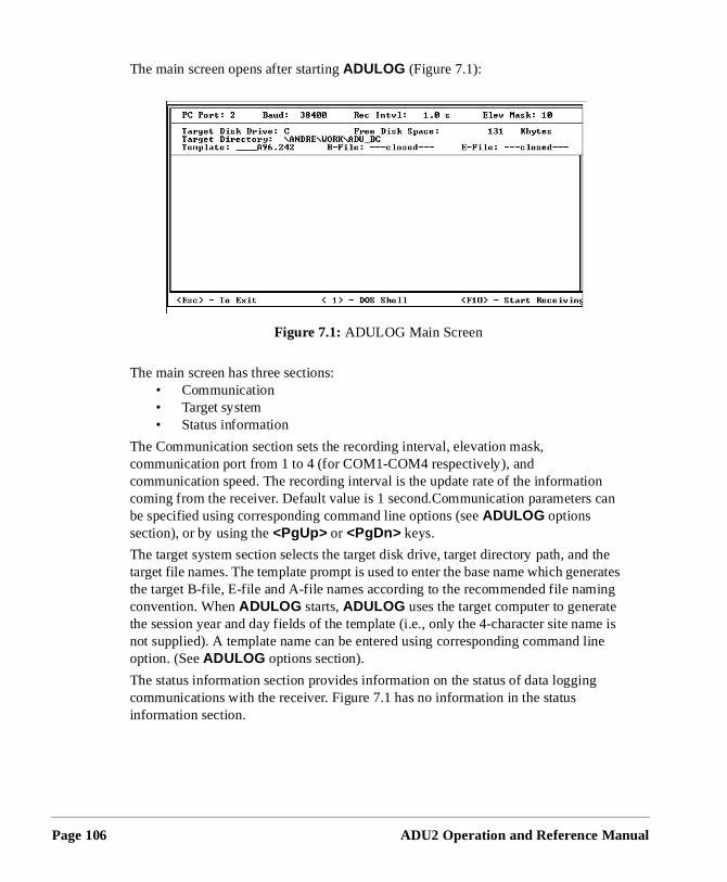
Page 106
n can
the erates ing e
e is ine
The main screen opens after starting ADULOG (Figure 7.1):
The main screen has three sections:• Communication• Target system• Status information
The Communication section sets the recording interval, elevation mask, communication port from 1 to 4 (for COM1-COM4 respectively), and communication speed. The recording interval is the update rate of the informatiocoming from the receiver. Default value is 1 second.Communication parametersbe specified using corresponding command line options (see ADULOG options section), or by using the <PgUp> or <PgDn> keys.
The target system section selects the target disk drive, target directory path, andtarget file names. The template prompt is used to enter the base name which genthe target B-file, E-file and A-file names according to the recommended file namconvention. When ADULOG starts, ADULOG uses the target computer to generatthe session year and day fields of the template (i.e., only the 4-character site namnot supplied). A template name can be entered using corresponding command loption. (See ADULOG options section).
The status information section provides information on the status of data loggingcommunications with the receiver. Figure 7.1 has no information in the status information section.
Figure 7.1: ADULOG Main Screen
ADU2 Operation and Reference Manual
ADULOG
AD
UL
OG
the
n
to
ant
Logging Data
1. Start ADULOG by typing adulog <ENTER> at the DOS prompt. The main screen opens.
2. Verify the PC Port listed at the bottom of the screen is correct. To changePC Port, press 1, 2, 3, or 4 corresponding to the PC Port.
3. Tab to the Baud field. If the baud rate is not set to 38400, then use Page Up and Page Down to set the baud rate to 38400.
4. Tab to the Recording Interval field. Type in the recording interval (in seconds).
5. Tab to the Elevation Mask field. There is no need to change the elevatiomask from 10°.
6. Tab to the Target Disk Drive field. If you wish your collection data savedfiles located on a drive other than the C drive, enter the drive letter.
7. Tab to the Directory field. Type in the name of the directory where you wyour data files saved.
8. Tab to the Template field. Type cali and press <ENTER>. The template creates the B and E-file names.
Page 107
Page 108
in
9. Press F10 to start collecting the data.
If target file names or template name are not properly specified, ADULOG issues a flashing warning “Invalid file names”.
If the target drive or path does not exist, ADULOG issues the flashing warning: Invalid drive and/or path specified .
If the files exist, ADULOG asks permission to overwrite them:
File B0001a96.301 already exists on disk.
Do you wish to [A]ppend, [O]verwrite, or a[B]ort
By hitting highlighted keys user can choose any of
offered ways .
After opening the target files, ADULOG tries to establish the data link. If the data link is not properly established, the following message appearsthe status section:
ERROR: While attempting to initialize the communications port, an RS-232 line status check indicates one of the following conditions:
1) Cables not connected properly (e.g., wrong receiver port)
2) Cables not fastened securely; and/or
3) Receiver power not “ON” Ensure cables are connected (with full NULL MODEM) and receiver power is on.
Press any key when ready to try again...
After five unsuccessful attempts to establish the data link ADULOG terminates with the message Too many attempts .
Once the data link is established, the message Installing RS-232
driver on COM2 appears in the status section.
10. A dialog box asks
Auto SV selection for best PDOP?
The answer affects the algorithm of selection satellites depending on whether this recording is used for antenna calibration or not.
ADU2 Operation and Reference Manual
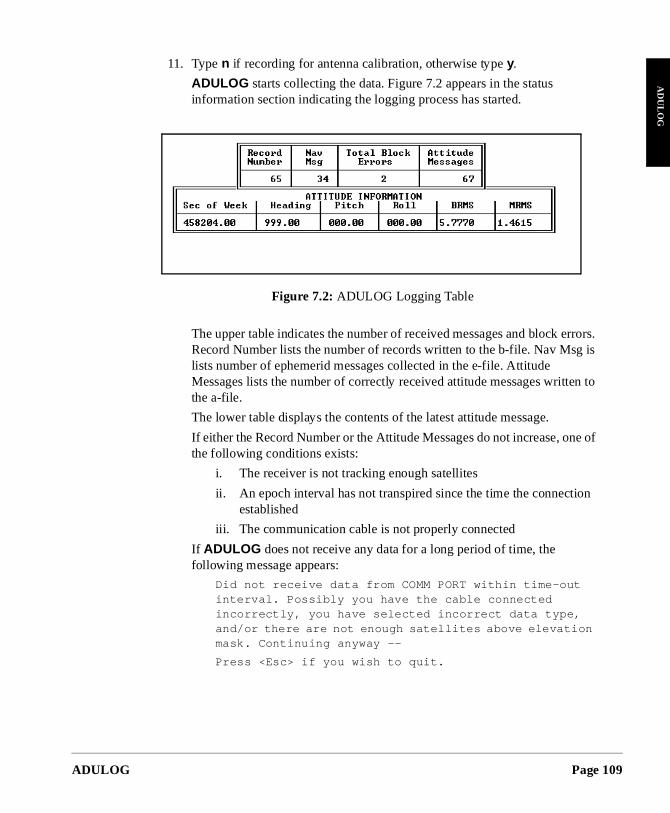
ADULOG
AD
UL
OG
rrors. is
n to
e of
on
11. Type n if recording for antenna calibration, otherwise type y.
ADULOG starts collecting the data. Figure 7.2 appears in the status information section indicating the logging process has started.
The upper table indicates the number of received messages and block eRecord Number lists the number of records written to the b-file. Nav Msglists number of ephemerid messages collected in the e-file. Attitude Messages lists the number of correctly received attitude messages writtethe a-file.
The lower table displays the contents of the latest attitude message.
If either the Record Number or the Attitude Messages do not increase, onthe following conditions exists:
i. The receiver is not tracking enough satellites
ii. An epoch interval has not transpired since the time the connectiestablished
iii. The communication cable is not properly connected
If ADULOG does not receive any data for a long period of time, the following message appears:
Did not receive data from COMM PORT within time-out interval. Possibly you have the cable connected incorrectly, you have selected incorrect data type, and/or there are not enough satellites above elevation mask. Continuing anyway --
Press <Esc> if you wish to quit.
Figure 7.2: ADULOG Logging Table
Page 109
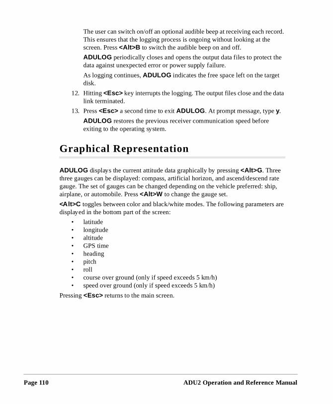
Page 110
ord.
he
ta
rate hip,
are
The user can switch on/off an optional audible beep at receiving each recThis ensures that the logging process is ongoing without looking at the screen. Press <Alt>B to switch the audible beep on and off.
ADULOG periodically closes and opens the output data files to protect tdata against unexpected error or power supply failure.
As logging continues, ADULOG indicates the free space left on the targetdisk.
12. Hitting <Esc> key interrupts the logging. The output files close and the dalink terminated.
13. Press <Esc> a second time to exit ADULOG . At prompt message, type y.
ADULOG restores the previous receiver communication speed before exiting to the operating system.
Graphical Representation
ADULOG displays the current attitude data graphically by pressing <Alt>G . Three three gauges can be displayed: compass, artificial horizon, and ascend/descendgauge. The set of gauges can be changed depending on the vehicle preferred: sairplane, or automobile. Press <Alt>W to change the gauge set.
<Alt>C toggles between color and black/white modes. The following parametersdisplayed in the bottom part of the screen:
• latitude• longitude• altitude• GPS time• heading• pitch• roll• course over ground (only if speed exceeds 5 km/h)• speed over ground (only if speed exceeds 5 km/h)
Pressing <Esc> returns to the main screen.
ADU2 Operation and Reference Manual
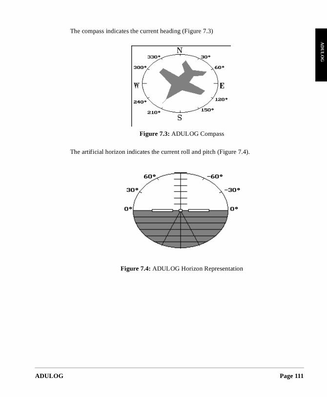
ADULOG
AD
UL
OG
The compass indicates the current heading (Figure 7.3)
The artificial horizon indicates the current roll and pitch (Figure 7.4).
Figure 7.3: ADULOG Compass
Figure 7.4: ADULOG Horizon Representation
Page 111
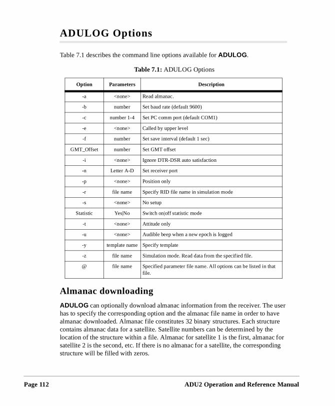
Page 112
ser ve re
e or ing
ADULOG Options
Table 7.1 describes the command line options available for ADULOG .
Almanac downloading
ADULOG can optionally download almanac information from the receiver. The uhas to specify the corresponding option and the almanac file name in order to haalmanac downloaded. Almanac file constitutes 32 binary structures. Each structucontains almanac data for a satellite. Satellite numbers can be determined by thlocation of the structure within a file. Almanac for satellite 1 is the first, almanac fsatellite 2 is the second, etc. If there is no almanac for a satellite, the correspondstructure will be filled with zeros.
Table 7.1: ADULOG Options
Option Parameters Description
-a <none> Read almanac.
-b number Set baud rate (default 9600)
-c number 1-4 Set PC comm port (default COM1)
-e <none> Called by upper level
-f number Set save interval (default 1 sec)
GMT_Offset number Set GMT offset
-i <none> Ignore DTR-DSR auto satisfaction
-n Letter A-D Set receiver port
-p <none> Position only
-r file name Specify RID file name in simulation mode
-s <none> No setup
Statistic Yes|No Switch on|off statistic mode
-t <none> Attitude only
-u <none> Audible beep when a new epoch is logged
-y template name Specify template
-z file name Simulation mode. Read data from the specified file.
@ file name Specified parameter file name. All options can be listed in that file.
ADU2 Operation and Reference Manual
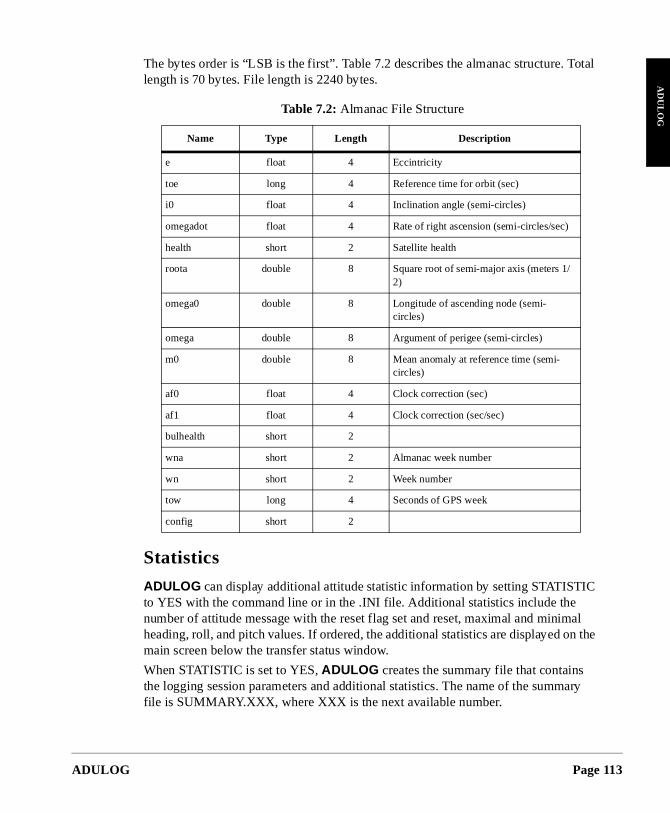
ADULOG
AD
UL
OG
otal
IC
al n the
ary
The bytes order is “LSB is the first”. Table 7.2 describes the almanac structure. Tlength is 70 bytes. File length is 2240 bytes.
Statistics
ADULOG can display additional attitude statistic information by setting STATISTto YES with the command line or in the .INI file. Additional statistics include the number of attitude message with the reset flag set and reset, maximal and minimheading, roll, and pitch values. If ordered, the additional statistics are displayed omain screen below the transfer status window.
When STATISTIC is set to YES, ADULOG creates the summary file that contains the logging session parameters and additional statistics. The name of the summfile is SUMMARY.XXX, where XXX is the next available number.
Table 7.2: Almanac File Structure
Name Type Length Description
e float 4 Eccintricity
toe long 4 Reference time for orbit (sec)
i0 float 4 Inclination angle (semi-circles)
omegadot float 4 Rate of right ascension (semi-circles/sec)
health short 2 Satellite health
roota double 8 Square root of semi-major axis (meters 1/2)
omega0 double 8 Longitude of ascending node (semi-circles)
omega double 8 Argument of perigee (semi-circles)
m0 double 8 Mean anomaly at reference time (semi-circles)
af0 float 4 Clock correction (sec)
af1 float 4 Clock correction (sec/sec)
bulhealth short 2
wna short 2 Almanac week number
wn short 2 Week number
tow long 4 Seconds of GPS week
config short 2
Page 113
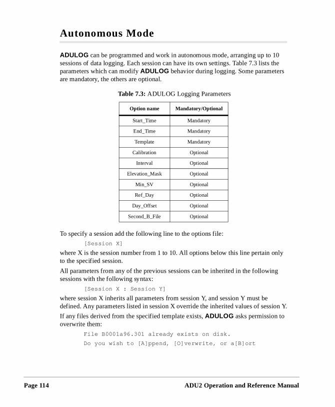
Page 114
0 the
ly
g
ion Y.
Autonomous Mode
ADULOG can be programmed and work in autonomous mode, arranging up to 1sessions of data logging. Each session can have its own settings. Table 7.3 listsparameters which can modify ADULOG behavior during logging. Some parametersare mandatory, the others are optional.
To specify a session add the following line to the options file:
[Session X]
where X is the session number from 1 to 10. All options below this line pertain onto the specified session.
All parameters from any of the previous sessions can be inherited in the followinsessions with the following syntax:
[Session X : Session Y]
where session X inherits all parameters from session Y, and session Y must be defined. Any parameters listed in session X override the inherited values of sess
If any files derived from the specified template exists, ADULOG asks permission to overwrite them:
File B0001a96.301 already exists on disk.
Do you wish to [A]ppend, [O]verwrite, or a[B]ort
Table 7.3: ADULOG Logging Parameters
Option name Mandatory/Optional
Start_Time Mandatory
End_Time Mandatory
Template Mandatory
Calibration Optional
Interval Optional
Elevation_Mask Optional
Min_SV Optional
Ref_Day Optional
Day_Offset Optional
Second_B_File Optional
ADU2 Operation and Reference Manual
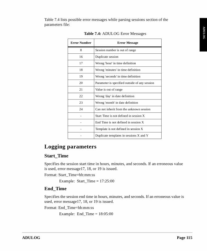
ADULOG
AD
UL
OG
value
is
Table 7.4 lists possible error messages while parsing sessions section of the parameters file:
Logging parameters
Start_Time
Specifies the session start time in hours, minutes, and seconds. If an erroneous is used, error message17, 18, or 19 is issued.
Format: Start_Time=hh:mm:ss
Example: Start_Time = 17:25:00
End_Time
Specifies the session end time in hours, minutes, and seconds. If an erroneous valueused, error message17, 18, or 19 is issued.
Format: End_Time=hh:mm:ss
Example: End_Time = 18:05:00
Table 7.4: ADULOG Error Messages
Error Number Error Message
8 Session number is out of range
16 Duplicate session
17 Wrong 'hour' in time definition
18 Wrong 'minutes' in time definition
19 Wrong 'seconds' in time definition
20 Parameter is specified outside of any session
21 Value is out of range
22 Wrong 'day' in date definition
23 Wrong 'month' in date definition
24 Can not inherit from the unknown session
- Start Time is not defined in session X
- End Time is not defined in session X
- Template is not defined in session X
- Duplicate templates in sessions X and Y
Page 115
Page 116
file
s n
.
on
an the or
Template
Specifies the template for the naming files, used to generate B-file, E-file, and A-names.
Format: Template = <template_name>
Example: Template=“0001”
Calibration
Selects if the recording session will be held in the antenna calibration mode. Thimode affects satellite selection algorithm during logging. By default the calibratiomode is OFF.
Format: Calibration=<Yes/No>
Example: Calibration = Yes
Interval
Sets the data update interval expressed in seconds. Default interval is 1 second
Format: Interval = <Number>
Example: Interval = 5
Elevation_Mask
Sets the satellite elevation mask in degrees. Default value is 10 degrees.
Format: Elevation_Mask=<Number>
Example: Elevation_Mask = 5
Min_SV
Specifies the minimum number of satellites that must be visible before the sessibegins to log data.
Format: Min_SV=<Number>
Example: Min_SV = 3
Ref_Day
Sets the reference day for the start and end logging times. If set to a date later thcurrent date, logging does not start until specified date. If set to a date previous equal to the current date, logging starts, and ends at the time specified with the Day_Offset parameter.
Format: Ref_Day=MM/DD/YY
Example: Ref_Day = 9/06/96
ADU2 Operation and Reference Manual
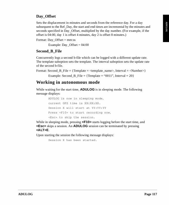
ADULOG
AD
UL
OG
and the
te. e rate
Day_Offset
Sets the displacement in minutes and seconds from the reference day. For a daysubsequent to the Ref_Day, the start and end times are incremental by the minutes seconds specified in Day_Offset, multiplied by the day number. (For example, if offset is 04:00, day 1 is offset 4 minutes, day 2 is offset 8 minutes.)
Format: Day_Offset = mm:ss
Example: Day_Offset = 04:00
Second_B_File
Concurrently logs a second b-file which can be logged with a different update raThe template suboption sets the template. The interval suboption sets the updatof the second b-file.
Format: Second_B_File = {Template = <template_name>, Interval = <Number>}
Example: Second_B_File = {Template = “0011”, Interval = 20}
Working in autonomous mode
While waiting for the start time, ADULOG is in sleeping mode. The following message displays:
ADULOG is now in sleeping mode,
current GPS time is XX:XX:XX.
Session X will start at YY:YY:YY
Press <F10> to start recording now,
<Esc> to skip the session.
While in sleeping mode, pressing <F10> starts logging before the start time, and <Esc> skips a session. An ADULOG session can be terminated by pressing <ALT>E .
Upon starting the session the following message displays:
Session X has been started.
Page 117
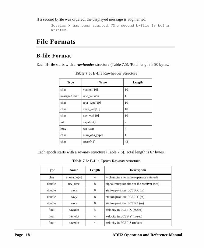
Page 118
If a second b-file was ordered, the displayed message is augmented:
Session X has been started.(The second b-file is being written)
File Formats
B-file Format
Each B-file starts with a rawheader structure (Table 7.5). Total length is 90 bytes.
Each epoch starts with a rawnav structure (Table 7.6). Total length is 67 bytes.
Table 7.5: B-file Rawheader Structure
Type Name Length
char version[10] 10
unsigned char raw_version 1
char rcvr_type[10] 10
char chan_ver[10] 10
char nav_ver[10] 10
int capability 2
long wn_start 4
char num_obs_types 1
char spare[42] 42
Table 7.6: B-file Epoch Rawnav structure
Type Name Length Description
char sitename[4] 4 4-character site name (operator entered)
double rcv_time 8 signal reception time at the receiver (sec)
double navx 8 station position: ECEF-X (m)
double navy 8 station position: ECEF-Y (m)
double navz 8 station position: ECEF-Z (m)
float navxdot 4 velocity in ECEF-X (m/sec)
float navydot 4 velocity in ECEF-Y (m/sec)
float navzdot 4 velocity in ECEF-Z (m/sec)
ADU2 Operation and Reference Manual
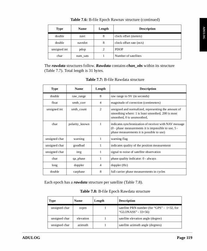
ADULOG
AD
UL
OG
of
ge
The rawdata structures follow. Rawdata contains chan_obs within its structure (Table 7.7). Total length is 31 bytes.
Each epoch has a rawdata structure per satellite (Table 7.8).
double navt 8 clock offset (meters)
double navtdot 8 clock offset rate (m/s)
unsigned int pdop 2 PDOP
char num_sats 1 Number of satellites
Table 7.7: B-file Rawdata structure
Type Name Length Description
double raw_range 8 raw range to SV (in seconds)
float smth_corr 4 magnitude of correction (centimeters)
unsigned int smth_count 2 unsigned and normalized, representing the amount smoothing where: 1 is least smoothed, 200 is most smoothed, 0 is unsmoothed,
char polarity_known 1 indicates synchronization of receiver with NAV messa(0 - phase measurements it is impossible to use, 5 - phase measurements it is possible to use)
unsigned char warning 1 warning flag
unsigned char goodbad 1 indicates quality of the position measurement
unsigned char ireg 1 signal to noise of satellite observation
char qa_phase 1 phase quality indicator: 0 - always
long doppler 4 doppler (Hz)
double carphase 8 full carrier phase measurements in cycles
Table 7.8: B-file Epoch Rawdata structure
Type Name Length Description
unsigned char svprn 1 satellite PRN number (for “GPS” - 1÷32, for “GLONASS” - 33÷56)
unsigned char elevation 1 satellite elevation angle (degree)
unsigned char azimuth 1 satellite azimuth angle (degrees)
Table 7.6: B-file Epoch Rawnav structure (continued)
Type Name Length Description
Page 119
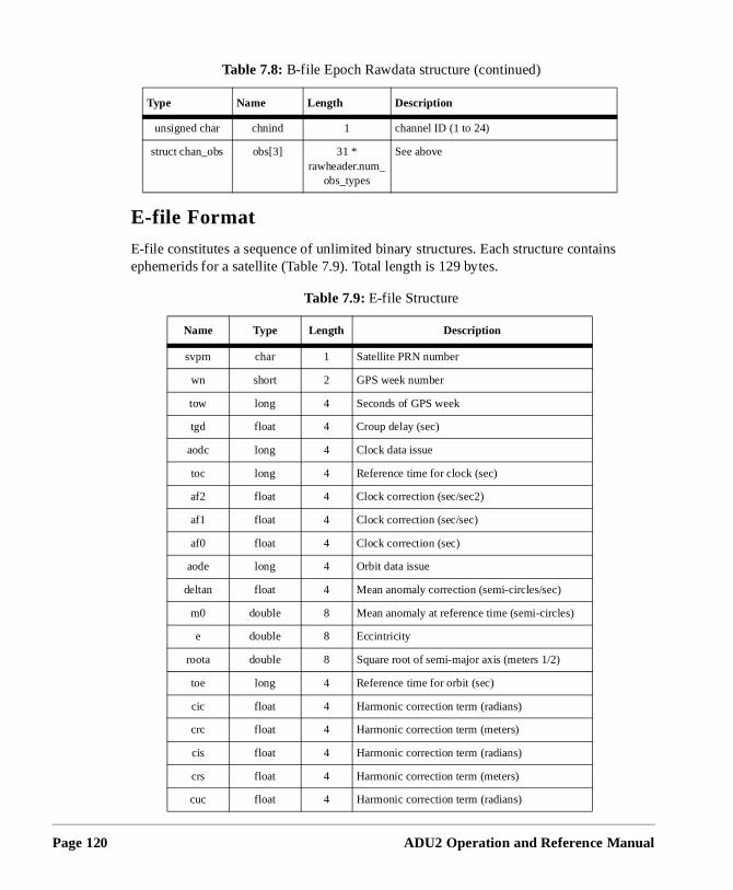
Page 120
ins
E-file Format
E-file constitutes a sequence of unlimited binary structures. Each structure contaephemerids for a satellite (Table 7.9). Total length is 129 bytes.
unsigned char chnind 1 channel ID (1 to 24)
struct chan_obs obs[3] 31 * rawheader.num_
obs_types
See above
Table 7.9: E-file Structure
Name Type Length Description
svprn char 1 Satellite PRN number
wn short 2 GPS week number
tow long 4 Seconds of GPS week
tgd float 4 Croup delay (sec)
aodc long 4 Clock data issue
toc long 4 Reference time for clock (sec)
af2 float 4 Clock correction (sec/sec2)
af1 float 4 Clock correction (sec/sec)
af0 float 4 Clock correction (sec)
aode long 4 Orbit data issue
deltan float 4 Mean anomaly correction (semi-circles/sec)
m0 double 8 Mean anomaly at reference time (semi-circles)
e double 8 Eccintricity
roota double 8 Square root of semi-major axis (meters 1/2)
toe long 4 Reference time for orbit (sec)
cic float 4 Harmonic correction term (radians)
crc float 4 Harmonic correction term (meters)
cis float 4 Harmonic correction term (radians)
crs float 4 Harmonic correction term (meters)
cuc float 4 Harmonic correction term (radians)
Table 7.8: B-file Epoch Rawdata structure (continued)
Type Name Length Description
ADU2 Operation and Reference Manual
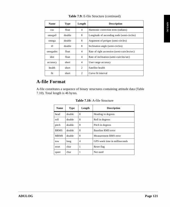
ADULOG
AD
UL
OG
A-file Format
A-file constitutes a sequence of binary structures containing attitude data (Table7.10). Total length is 46 bytes.
cus float 4 Harmonic correction term (radians)
omega0 double 8 Longitude of ascending node (semi-circles)
omega double 8 Argument of perigee (semi-circles)
i0 double 8 Inclination angle (semi-circles)
omegadot float 4 Rate of right ascension (semi-cuircles/sec)
idot float 4 Rate of inclination (semi-cuircles/sec)
accuracy short 4 User range accuracy
health short 2 Satellite health
fit short 2 Curve fit interval
Table 7.10: A-file Structure
Name Type Length Description
head double 8 Heading in degrees
roll double 8 Roll in degrees
pitch double 8 Pitch in degrees
BRMS double 8 Baseline RMS error
MRMS double 8 Measurement RMS error
tow long 4 GPS week time in milliseconds
reset char 1 Reset flag
spare char 1 Not used
Table 7.9: E-file Structure (continued)
Name Type Length Description
Page 121

Page 122
ADU2 Operation and Reference Manual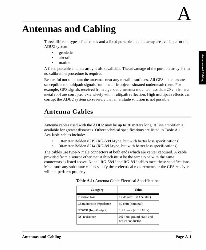
Antennas a
Anten
nas and Cabling
r the
is that
are
om a can
able
tions. eiver
Three different types of antennas and a fixed portable antenna array are available foADU2 system:
• geodetic• aircraft• marine
A fixed portable antenna array is also available. The advantage of the portable array no calibration procedure is required.
Be careful not to mount the antennas near any metallic surfaces. All GPS antennas susceptible to multipath signals from metallic objects situated underneath them. For example, GPS signals received from a geodetic antenna mounted less than 20 cm frmetal roof are corrupted extensively with multipath reflection. High multipath effects corrupt the ADU2 system so severely that an attitude solution is not possible.
Antenna Cables
Antenna cables used with the ADU2 may be up to 30 meters long. A line amplifier isavailable for greater distances. Other technical specifications are listed in Table A.1.Available cables include:
• 10-meter Belden 8219 (RG-58/U-type, but with better loss specifications) • 30-meter Belden 8214 (RG-8/U-type, but with better loss specifications)
The cables use type-N male connectors at both ends which are center captured. A cprovided from a source other that Ashtech must be the same type with the same connectors as listed above. Not all RG-58/U and RG-8/U cables meet these specificaMake sure any substitute cables satisfy these electrical requirements or the GPS recwill not perform properly.
Table A.1: Antenna Cable Electrical Specifications
Category Value
Insertion loss 17 db max. (at 1.5 GHz)
Characteristic impedance 50 ohm (nominal)
/VSWR (Input/output) 1.1:1 max (at 1.5 GHz)
DC resistance 0.5 ohm ground braid and center conductor
A
Antennas and Cablingnd Cabling Page A-1
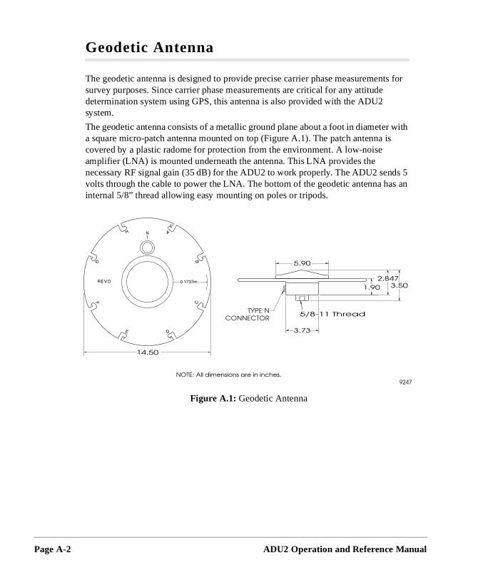
Page A-2
ts for
r with is
s an
Geodetic Antenna
The geodetic antenna is designed to provide precise carrier phase measuremensurvey purposes. Since carrier phase measurements are critical for any attitude determination system using GPS, this antenna is also provided with the ADU2 system.
The geodetic antenna consists of a metallic ground plane about a foot in diametea square micro-patch antenna mounted on top (Figure A.1). The patch antenna covered by a plastic radome for protection from the environment. A low-noise amplifier (LNA) is mounted underneath the antenna. This LNA provides the necessary RF signal gain (35 dB) for the ADU2 to work properly. The ADU2 sends 5 volts through the cable to power the LNA. The bottom of the geodetic antenna hainternal 5/8” thread allowing easy mounting on poles or tripods.
Figure A.1: Geodetic Antenna
ADU2 Operation and Reference Manual
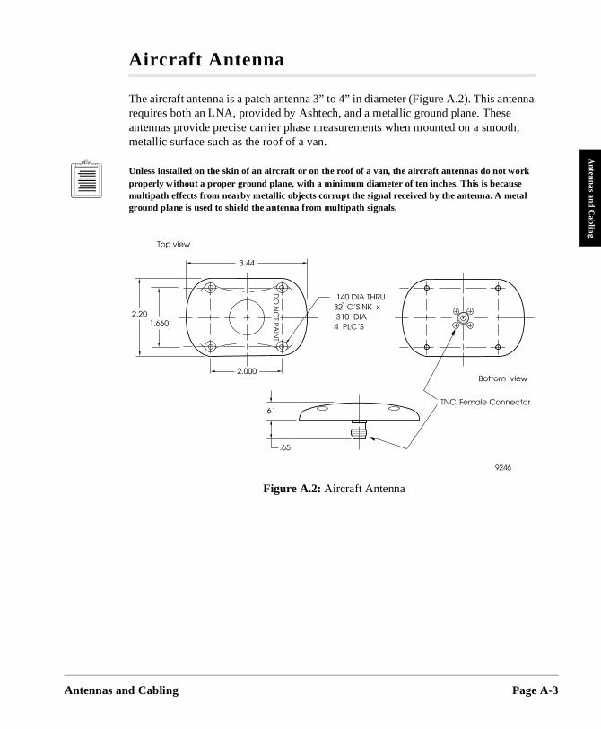
Antennas a
Antennas and C
abling
enna
oth,
Aircraft Antenna
The aircraft antenna is a patch antenna 3” to 4” in diameter (Figure A.2). This antrequires both an LNA, provided by Ashtech, and a metallic ground plane. These antennas provide precise carrier phase measurements when mounted on a smometallic surface such as the roof of a van.
Unless installed on the skin of an aircraft or on the roof of a van, the aircraft antennas do not work properly without a proper ground plane, with a minimum diameter of ten inches. This is because multipath effects from nearby metallic objects corrupt the signal received by the antenna. A metal ground plane is used to shield the antenna from multipath signals.
Figure A.2: Aircraft Antenna
nd Cabling Page A-3
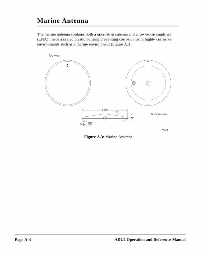
Page A-4
r
Marine Antenna
The marine antenna contains both a microstrip antenna and a low-noise amplifie(LNA) inside a sealed plastic housing preventing corrosion from highly corrosiveenvironments such as a marine environment (Figure A.3).
Figure A.3: Marine Antenna
ADU2 Operation and Reference Manual
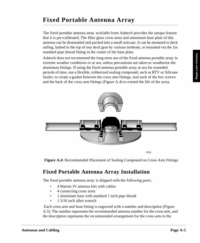
Antennas a
Antennas and C
abling
ture his o deck e 1in
ray in e the
cone crews
ure , and
e
ings
Fixed Portable Antenna Array
The fixed portable antenna array available from Ashtech provides the unique feathat it is pre-calibrated. The fiber glass cross arms and aluminum base plate of tantenna can be dismantled and packed into a small suitcase. It can be mounted trailing, lashed to the top of any deck gear by various methods, or mounted via thstandard pipe thread fitting in the center of the base plate.
Ashtech does not recommend the long-term use of the fixed antenna portable arextreme weather conditions or at sea, unless precautions are taken to weatherizaluminum fittings. If using the fixed antenna portable array at sea for extended periods of time, use a flexible, rubberized sealing compound, such as RTV or SiliSealer, to create a gasket between the cross arm fittings, seal each of the hex sand the back of the cross arm fittings (Figure A.4) to extend the life of the array.
Fixed Portable Antenna Array Installation
The fixed portable antenna array is shipped with the following parts:
• 4 Marine IV antenna kits with cables• 4 connecting cross arms• 1 aluminum base with standard 1 inch pipe thread• 1 3/16 inch allen wrench
Each cross arm and base fitting is engraved with a number and description (FigA.5). The number represents the recommended antenna number for the cross armthe description represents the recommended arrangement for the cross arm in th
Figure A.4: Recommended Placement of Sealing Compound on Cross Arm Fitt
nd Cabling Page A-5
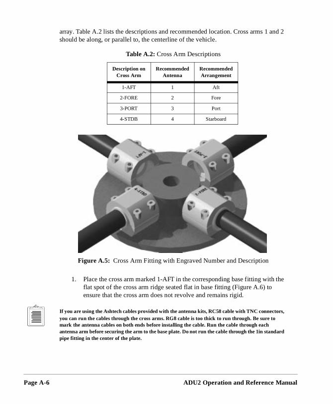
Page A-6
nd 2
the
array. Table A.2 lists the descriptions and recommended location. Cross arms 1 ashould be along, or parallel to, the centerline of the vehicle.
1. Place the cross arm marked 1-AFT in the corresponding base fitting withflat spot of the cross arm ridge seated flat in base fitting (Figure A.6) to ensure that the cross arm does not revolve and remains rigid.
If you are using the Ashtech cables provided with the antenna kits, RC58 cable with TNC connectors, you can run the cables through the cross arms. RG8 cable is too thick to run through. Be sure to mark the antenna cables on both ends before installing the cable. Run the cable through each antenna arm before securing the arm to the base plate. Do not run the cable through the 1in standard pipe fitting in the center of the plate.
Table A.2: Cross Arm Descriptions
Description on Cross Arm
Recommended Antenna
Recommended Arrangement
1-AFT 1 Aft
2-FORE 2 Fore
3-PORT 3 Port
4-STDB 4 Starboard
Figure A.5: Cross Arm Fitting with Engraved Number and Description
ADU2 Operation and Reference Manual
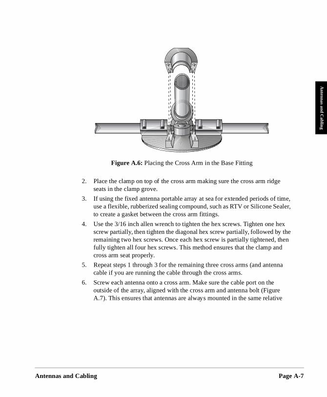
Antennas a
Antennas and C
abling
e
aler,
ex the hen
na
e
2. Place the clamp on top of the cross arm making sure the cross arm ridgseats in the clamp grove.
3. If using the fixed antenna portable array at sea for extended periods of time, use a flexible, rubberized sealing compound, such as RTV or Silicone Seto create a gasket between the cross arm fittings.
4. Use the 3/16 inch allen wrench to tighten the hex screws. Tighten one hscrew partially, then tighten the diagonal hex screw partially, followed by remaining two hex screws. Once each hex screw is partially tightened, tfully tighten all four hex screws. This method ensures that the clamp andcross arm seat properly.
5. Repeat steps 1 through 3 for the remaining three cross arms (and antencable if you are running the cable through the cross arms.
6. Screw each antenna onto a cross arm. Make sure the cable port on the outside of the array, aligned with the cross arm and antenna bolt (FigureA.7). This ensures that antennas are always mounted in the same relativ
Figure A.6: Placing the Cross Arm in the Base Fitting
nd Cabling Page A-7
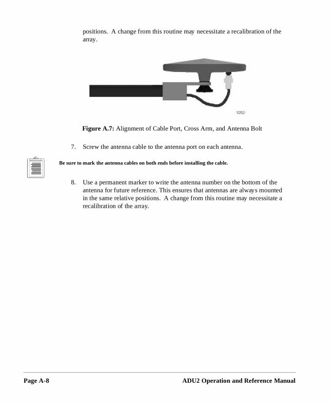
Page A-8
the
the unted te a
positions. A change from this routine may necessitate a recalibration ofarray.
7. Screw the antenna cable to the antenna port on each antenna.
Be sure to mark the antenna cables on both ends before installing the cable.
8. Use a permanent marker to write the antenna number on the bottom of antenna for future reference. This ensures that antennas are always moin the same relative positions. A change from this routine may necessitarecalibration of the array.
Figure A.7: Alignment of Cable Port, Cross Arm, and Antenna Bolt
ADU2 Operation and Reference Manual
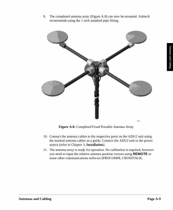
Antennas a
Antennas and C
abling
h
ing wer
ever
9. The completed antenna array (Figure A.8) can now be mounted. Ashtecrecommends using the 1 inch standard pipe fitting.
10. Connect the antenna cables to the respective ports on the ADU2 unit usthe marked antenna cables as a guide. Connect the ADU2 unit to the posource (refer to Chapter 3, Installation ).
11. The antenna array is ready for operation. No calibration is required, howyou need to input the relative antenna position vectors using REMOTE or some other communications software (PROCOMM, CROSSTALK,
Figure A.8: Completed Fixed Portable Antenna Array
nd Cabling Page A-9
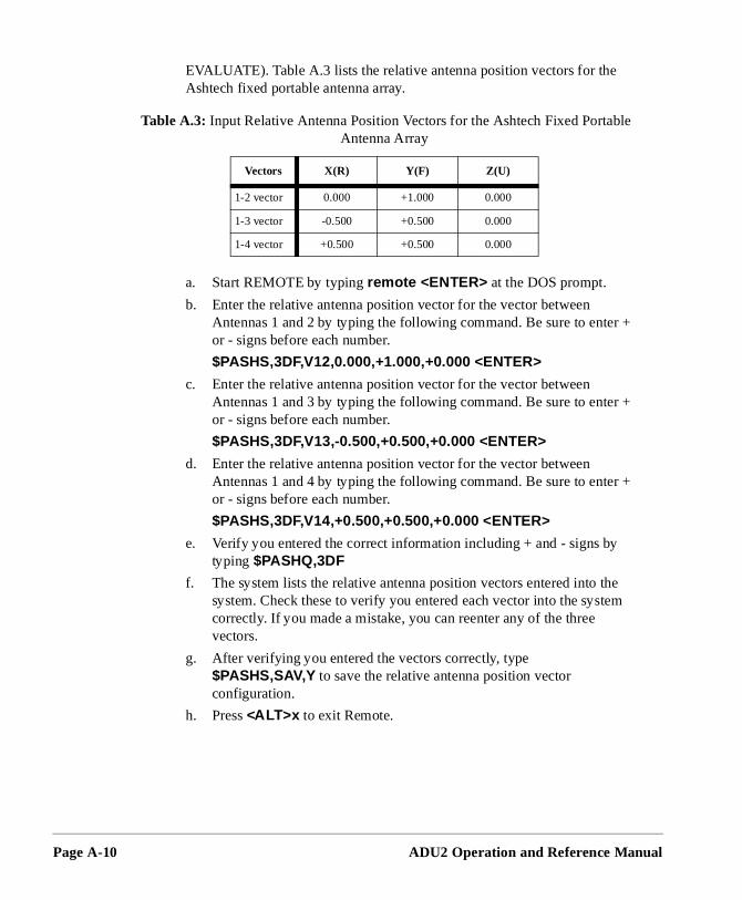
Page A-10
r +
r +
r +
e m
le
EVALUATE). Table A.3 lists the relative antenna position vectors for the Ashtech fixed portable antenna array.
a. Start REMOTE by typing remote <ENTER> at the DOS prompt.
b. Enter the relative antenna position vector for the vector between Antennas 1 and 2 by typing the following command. Be sure to enteor - signs before each number.
$PASHS,3DF,V12,0.000,+1.000,+0.000 <ENTER>
c. Enter the relative antenna position vector for the vector between Antennas 1 and 3 by typing the following command. Be sure to enteor - signs before each number.
$PASHS,3DF,V13,-0.500,+0.500,+0.000 <ENTER>
d. Enter the relative antenna position vector for the vector between Antennas 1 and 4 by typing the following command. Be sure to enteor - signs before each number.
$PASHS,3DF,V14,+0.500,+0.500,+0.000 <ENTER>
e. Verify you entered the correct information including + and - signs bytyping $PASHQ,3DF
f. The system lists the relative antenna position vectors entered into thsystem. Check these to verify you entered each vector into the systecorrectly. If you made a mistake, you can reenter any of the three vectors.
g. After verifying you entered the vectors correctly, type $PASHS,SAV,Y to save the relative antenna position vector configuration.
h. Press <ALT>x to exit Remote.
Table A.3: Input Relative Antenna Position Vectors for the Ashtech Fixed PortabAntenna Array
Vectors X(R) Y(F) Z(U)
1-2 vector 0.000 +1.000 0.000
1-3 vector -0.500 +0.500 0.000
1-4 vector +0.500 +0.500 0.000
ADU2 Operation and Reference Manual
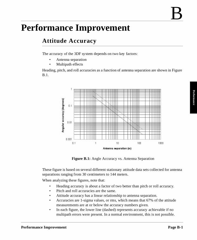
B
Performance ImprovementPerforman
Perform
ance
igure
tenna
e
Attitude Accuracy
The accuracy of the 3DF system depends on two key factors:
• Antenna separation • Multipath effects
Heading, pitch, and roll accuracies as a function of antenna separation are shown in FB.1.
These figure is based on several different stationary attitude data sets collected for anseparations ranging from 30 centimeters to 144 meters.
When analyzing these figures, note that:
• Heading accuracy is about a factor of two better than pitch or roll accuracy. • Pitch and roll accuracies are the same. • Attitude accuracy has a linear relationship to antenna separation. • Accuracies are 1-sigma values, or rms, which means that 67% of the attitud
measurements are at or below the accuracy numbers given. • In each figure, the lower line (dashed) represents accuracy achievable if no
multipath errors were present. In a normal environment, this is not possible.
Figure B.1: Angle Accuracy vs. Antenna Separation
ce Improvement Page B-1
Page B-2
e tem
n it
n be en
two ion
er are
hicle ce ke
e, ers of
ithin
re
sured s l when
Multipath effects from typical environments are depicted by the upper lin(solid). For a given antenna separation, the performance of the 3DF sysshould lie somewhere near the upper line.
• A moving vehicle does not experience as many multipath effects as wheis stationary. This is because multipath is a correlated error. Correlated errors become more noise-like under vehicle dynamics and therefore cafiltered out. Therefore, accuracy results improve toward the lower line whthe vehicle is moving.
• Heading accuracy is directly proportional to the separation between the antennas which define the heading baseline, however too much separatcan result in differential multipath between antennas and introduction of vessel or vehicle flexing into the attitude solution. These two factors are detrimental to heading accuracy. Antenna separations less than one metnot advised, and antennas should not be located so that any of the threevectors are co-linear. Antenna separations of three to five meters are recommended.
Antenna location is the single most important aspect of successful attitude computation.
Attitude Offset Angles
Angles Attitude offset angles are the angle differences (positive clockwise) in heading, pitch, and roll that exist between the ADU2 antenna system and the ve(“truth”). These offset angles are essentially constant bias errors from truth. Sinthe attitude given by a ADU2 system is so accurate (one milliradian or better), tacare when mounting antennas on a vehicle to prevent unnecessary offset angles.
For example, mount two of the four ADU2 antennas on the centerline of a vehiclseparated by 2 meters. Both of these antennas must be placed within 2 millimetthe centerline to obtain subdegree accuracy with no heading offset angle being induced. Separating the two antennas by 30 meters allows you to place them w30 millimeters of the vehicle centerline to obtain the same accuracy.
The phase center of an antenna (both geodetic and aircraft types, described in Appendix B) is not in the exact physical center of the antenna. Therefore, whentrying to mount two antennas along the vehicle centerline, make sure that both aplaced in the same orientation.
If three of the four antennas cannot be mounted in the exact plane parallel to thevehicle body, pitch and roll offset angles are induced. These angles can be meaby taking into account the different heights of the antennas. Also, if the vehicle istationary and has been oriented in space such that it has zero pitch and zero rolperforming the initial relative antenna position survey, the program ADJENU.EXE
ADU2 Operation and Reference Manual
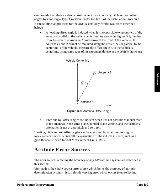
Performan
Perform
ance
re.
the ine
the
ngs:
ree e’s
a
ed in
can provide the relative antenna position vectors without any pitch and roll offsetangles by choosing a Type 1 rotation. Refer to Step 3 of the Installation Procedu
Attitude offset angles exist for the 3DF system only for the two cases described below:
• A heading offset angle is induced when it is not possible to mount two ofantennas parallel to the vehicle centerline. As shown in Figure B.2, the lfrom Antenna 1 to Antenna 2 points toward the front of the vehicle. If Antennas 1 and 2 cannot be mounted along the centerline (or parallel tocenterline) of the vehicle, measure the offset angle B to the vehicle’s centerline, using some type of measurement device or the vehicle drawi
• Pitch and roll offset angles are induced when it is not possible to mount thof the antennas in the same plane, parallel to the vehicle, and the vehiclorientation is not at zero pitch and zero roll.
Heading, pitch and roll offset angles can be measured by other precise angular measurement devices which tell the orientation of the vehicle in space, such as gyro-theodolite or an Inertial Measurement Unit (IMU).
Attitude Error Sources
The error sources affecting the accuracy of any GPS attitude system are describthis section.
Multipath is the single largest error source which limits the accuracy of attitude determination systems. It is a slowly varying error which occurs from reflecting
Figure B.2: Antenna Offset Angle
ce Improvement Page B-3
Page B-4
mes cts
stant, a ce ading an
de er
ich
n be DM, ).
offset, to
e e helpful f the g ithin
ing
to for and .
objects (such as metal or water) in the vehicle’s environment. As a vehicle becomore dynamic, the multipath error becomes less. This is because reflecting objefor a dynamic vehicle change (in location and orientation), causing the multipatherror to average out.
Antenna separation plays a key role in determining the accuracy of the attitude solution. Since the relative antenna positioning accuracy can be considered contranslating position accuracy to angular accuracy only depends upon the antennseparation. The further apart the antennas, the better the angular accuracy. Sinheading accuracy is a function of antenna separation, multipath can affect the heaccuracy. Pitch and roll accuracy’s are usually a factor of 1.5 to 3 times worse ththe heading accuracy.
Phase measurement error (with no multipath) accounts for the noise of the attitusolution. This type of error is small and is insignificant when compared to the otherror sources.
A bias-type heading error can occur when trying to mount Antennas 1 and 2 (whprovide the heading direction) along or parallel to, the centerline of a vehicle. Toprevent this, determine the heading offset angle before installation.
For example, most ship mounting restrictions do not allow the installation of two GPSantennas along, or exactly parallel to its centerline. The heading offset angle caprecisely determined while the ship is moored to the pier using a theodolite and Eor a total station. First establish an azimuth from a dockside instrument point (IPUsing the assumed coordinates at the IP, observe sideshots (angle and distancemeasurements) to the prism targets which have been placed both at the ADU2 antennas and at points known to be on the centerline of the vessel. For heading only antennas 1 and 2 need to be targeted. Then use the sideshot observationscalculate the coordinates for all targets. The inverses between relevant target coordinates then provide the offset angle between the Antenna 1-2 vector and thvessel centerline. To negate the effect of any slight vessel movements during thobservations, measure several rounds to each target and mean the results. It is to locate the IP at a distance from the vessel sufficient to ensure rapid pointings otheodolite, since the time delay between sideshots is a critical factor in minimizinthe errors caused by vessel movement. An experienced instrument person usinggood techniques should be able to determine relative position of the targeted objects wa centimeter under good conditions.
Another possible method of determining any alignment between the ADU2 headvector and the vessel centerline is to perform a simple comparison of ADU2 heading data (make sure no heading offset has been entered in the receiver setup) with readings from the ship’s gyrocompass if the ship is so equipped. It is advisable perform this comparison continuously for a period of at least 84 minutes to allowthe Schuler oscillation of the gyrocompass. If possible, the ship should be swungre-moored with its opposite side to the pier, and the comparison performed again
ADU2 Operation and Reference Manual
Performan
Perform
ance
e
ause PS a is next.
incur
r
lmost fore,
rrors h.
tive aster
l as d
hile
it). r
This cancels the bias which could be induced by any physical misalignment of thgyrocompass mounting.
Similar methods can be used to determine pitch and roll offset angles.
Microstrip antennas should be used for GPS attitude determination systems becthey have a stable phase center (it does not fluctuate depending on where the Gsatellites are in the sky). Also, the manufacturing process of a microstrip antennsuch that the location of its phase center does not vary from one antenna to the But the phase center is usually not the physical center of a microstrip antenna. Therefore, orienting the antennas in the same direction is important so as not to bias errors in the heading solution.
When comparing the attitude solution of the ADU2 with any type of gyro, anotheerror source should be considered. The ADU2’s solution is raw, no filtering is performed and is provided at a 2Hz rate . On the other hand, a gyro’s output is aalways smoothed in some way and give at a much higher rate (5 to 40 Hz). Thereyou must interpolate the attitude data from the ADU2 and somehow defilter the gryro’s output data for a time comparison.
Attitude Quality Indicators
To assure a good attitude solution has been computed, the MRMS and BRMS eare used as quality indicators and are checked against maximums at every epoc
A wrong attitude solution would cause both the MRMS and BRMS errors to continually grow larger. The rate at which these errors grow depends on the relamotion between the vehicle and satellites. The higher the vehicle dynamics, the fthe error growth rate of a false solution.
Also, as Position Dilution of Precision (PDOP) becomes higher, the BRMS error grows as well. Typically, GPS can provide good attitude information as long as PDOPis below 6, which is approximately 95% of the time with the full 24-satellite constellation, worldwide. (Note that with GPS the high latitudes will generally experience higher PDOPs than the equatorial latitudes.)
Multipath significantly affects the computed BRMS error, causing it to rise and falthe antennas receive "constructive" and "destructive" interference. The period anamplitude of the multipath oscillations varies significantly depending on vehicle dynamics and environment. Static vehicles are the most affected by multipath wdynamic vehicles' multipath errors tend to average out.
The maximum limit for the BRMS error is set to 4 centimeters. This limit may be increased for vehicles in high multipath environments (that is, 6-8 centimeter limThe maximum limit for the MRMS error is 5 millimeters and may be increased fohigh dynamic vehicles (that is, 6-7 millimeter limit).
ce Improvement Page B-5
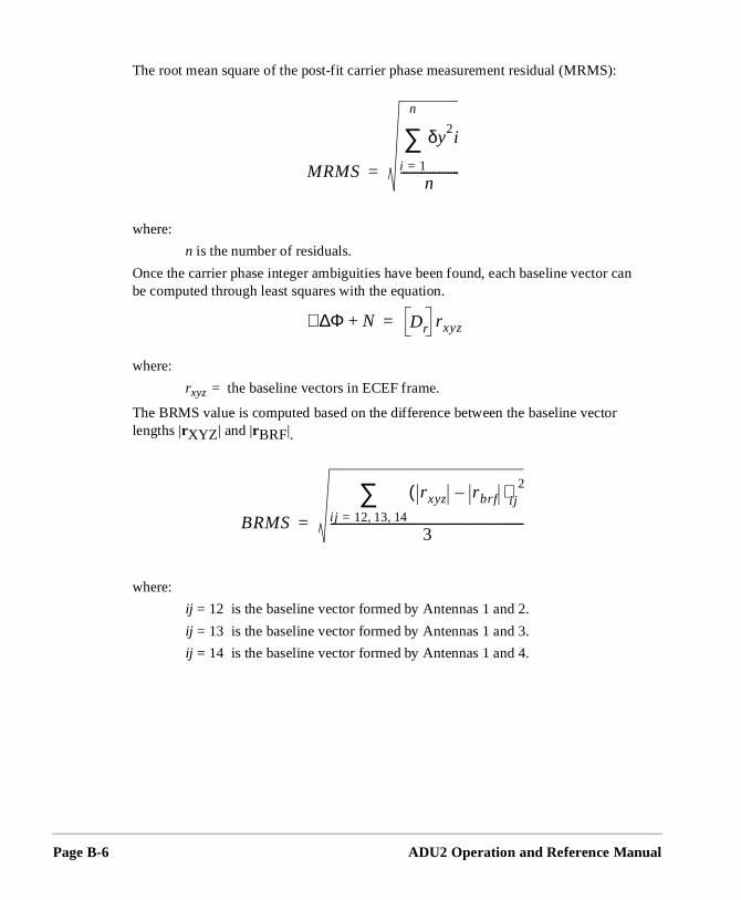
Page B-6
):
tor
The root mean square of the post-fit carrier phase measurement residual (MRMS
where:
n is the number of residuals.
Once the carrier phase integer ambiguities have been found, each baseline vector canbe computed through least squares with the equation.
where:
rxyz = the baseline vectors in ECEF frame.
The BRMS value is computed based on the difference between the baseline veclengths |rXYZ | and |rBRF|.
where:
ij = 12 is the baseline vector formed by Antennas 1 and 2.
ij = 13 is the baseline vector formed by Antennas 1 and 3.
ij = 14 is the baseline vector formed by Antennas 1 and 4.
MRMS
δy2i
i 1=
n
∑n
--------------------=
Φ∆∇ N+ Dr rxyz=
BRMS
rxyz rbrf–( )i j2
i j 12 13 14, ,=
∑3
------------------------------------------------------------------=
ADU2 Operation and Reference Manual
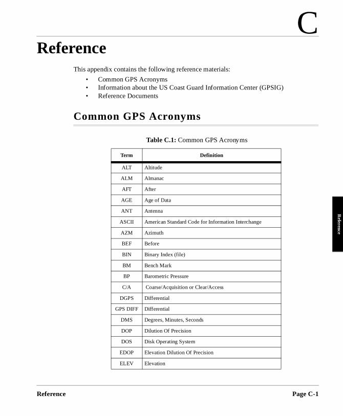
C
ReferenceReference
Reference
This appendix contains the following reference materials:
• Common GPS Acronyms• Information about the US Coast Guard Information Center (GPSIG) • Reference Documents
Common GPS Acronyms
Table C.1: Common GPS Acronyms
Term Definition
ALT Altitude
ALM Almanac
AFT After
AGE Age of Data
ANT Antenna
ASCII American Standard Code for Information Interchange
AZM Azimuth
BEF Before
BIN Binary Index (file)
BM Bench Mark
BP Barometric Pressure
C/A Coarse/Acquisition or Clear/Access
DGPS Differential
GPS DIFF Differential
DMS Degrees, Minutes, Seconds
DOP Dilution Of Precision
DOS Disk Operating System
EDOP Elevation Dilution Of Precision
ELEV Elevation
Page C-1
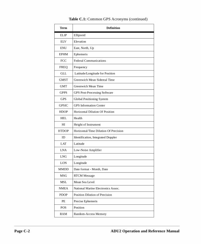
Page C-2
ELIP Ellipsoid
ELV Elevation
ENU East, North, Up
EPHM Ephemeris
FCC Federal Communications
FREQ Frequency
GLL Latitude/Longitude for Position
GMST Greenwich Mean Sidereal Time
GMT Greenwich Mean Time
GPPS GPS Post-Processing Software
GPS Global Positioning System
GPSIC GPS Information Center
HDOP Horizontal Dilution Of Position
HEL Health
HI Height of Instrument
HTDOP Horizontal/Time Dilution Of Precision
ID Identification, Integrated Doppler
LAT Latitude
LNA Low-Noise Amplifier
LNG Longitude
LON Longitude
MMDD Date format - Month, Date
MSG RTCM Message
MSL Mean Sea Level
NMEA National Marine Electronics Assoc.
PDOP Position Dilution of Precision
PE Precise Ephemeris
POS Position
RAM Random-Access Memory
Table C.1: Common GPS Acronyms (continued)
Term Definition
ADU2 Operation and Reference Manual
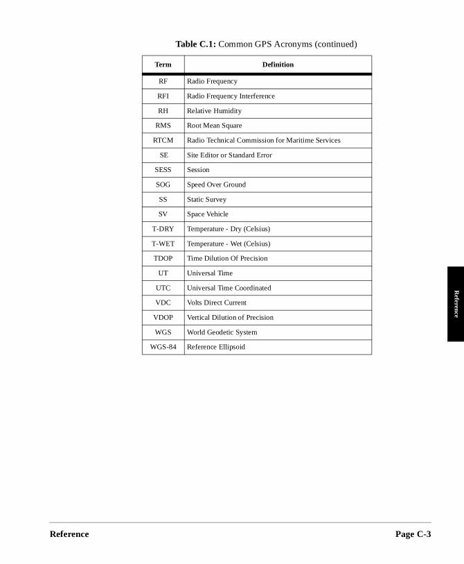
Reference
Reference
RF Radio Frequency
RFI Radio Frequency Interference
RH Relative Humidity
RMS Root Mean Square
RTCM Radio Technical Commission for Maritime Services
SE Site Editor or Standard Error
SESS Session
SOG Speed Over Ground
SS Static Survey
SV Space Vehicle
T-DRY Temperature - Dry (Celsius)
T-WET Temperature - Wet (Celsius)
TDOP Time Dilution Of Precision
UT Universal Time
UTC Universal Time Coordinated
VDC Volts Direct Current
VDOP Vertical Dilution of Precision
WGS World Geodetic System
WGS-84 Reference Ellipsoid
Table C.1: Common GPS Acronyms (continued)
Term Definition
Page C-3
Page C-4
plans e
es
n s ation le 24
7.
ation each ion
GPSIG Information
Since February 1989, the US Coast Guard has developed the requirements andfor the Civil GPS Service (CGS) and has begun to implement these services. Thfour CGS functions recognized by the Coast Guard are listed below:
• Provide a GPS Operational Advisory Broadcast (OAB) • Process applications for the civil use of GPS PPS (Precise Positioning
Service) • Provide precise GPS satellite ephemeris data • Provide a government interface for civil GPS users
Two agencies perform these functions:
• The GPS Information Center - provides the OAB and precise ephemerid• The PPS Program Office - processes civil applications to PPS access
The primary source of information for the OAB is the GPS control center at FalcoAir Force Base in Colorado Springs, Colorado. The OAB originates at GPSIC inAlexandria VA and is broadcast during normal working hours, 8AM to 4PM EST,Monday through Friday, except Federal holidays. An answering machine recordmessages after hours, and calls are returned the next working day. OAB informis updated only during normal working hours, but advisory services are accessibhours, 7 days. OAB presents the following information:
• Status - Current constellation health and availability • Outages - Recent and future satellite down time • Almanac - Current projected orbit data for GPS coverage and visibility
predictions • Other - General GPS information and some user documentation
Satellite visibility and coverage predictions are not offered by GPSIC. These services are available from commercial sources or commercially available software.
GPSIC Voice Recording
This tape message contains current satellite status and outage information. Therecording is available 24 hours 7 days and can be heard by dialing 703-313-590The recording is updated at least daily during normal GPSIC working hours.
WWV/WWVH Voice Broadcasts
These short-wave voice broadcasts contain current GPS status and outage informin a 45-second message. The message is broadcast at minutes 14 and 15 pasthour on WWV and at minutes 43 and 44 past the hour on WWVH. The informat
ADU2 Operation and Reference Manual
Reference
Reference
arine ccur.
ion. s. To
4).
ome
tage, he
act:
is updated at least daily during normal GPSIC working hours. WWV and WWVHoperate at 5.0, 10.0, and 15.0 MHz.
US Coast Guard Broadcast to Mariners
GPS status, future outages, and safety advisories are transmitted on the VHF mradio band. The information is updated weekly and whenever satellite outages o
GPSIC Computer Bulletin Board Service (BBS)
GPSIC operates BBS that lists status, outage, almanac, and other GPS informatThe BBS is available to any user free of charge, except for normal telephone feeaccess the BBS, the user will need a computer, a modem, and communication software. Users obtain a User ID password on line during the first session. The following information will be found useful in connecting to the GPSIC BBS.
Call 703-866-38901 for connections at 300 bps/Bell103, 1200 bps/Bell 212A, 2400bps/CCITT V.22bis, no MNP capability (common US specs, Supramodem 2400).
Call 703-866-38932 for connections at 1200 bps/CCITT V.22bis, 1200 bps/CCITT V.22, 1200 bps/Bell 212A, 2400 bps/CCITT V.22bis, 4800 bps/CCITT V.32, 9600bps/CCITT V.32 and MNP capabilities level 2,3,4,5, none (DigiCom Systems 962
Communications parameters at both numbers: Asynchronous, no parity, 8 data bits, full duplex, 1 stop bit (10-bit word).
The BBS ignores the 8th bit of data, restricting the character set to the lower 128ASCII values. The BBS also checks for ANSI graphics capability, and employs sANSI graphics if the user’s equipment can display them. All users get the sameinformation, but non-ANSI users will not see color images.
Defense Mapping Agency (ANMS)
The Defense Mapping Agency’s Navigation Information Network, Automated Notice to Mariners System is a computer database that contains GPS status, oualmanac, and other information. GPSIC updates the information at least daily. Tinformation is contained in query number 85.
Users must register with DMA. To obtain a user ID and information booklet, cont
DMA Hydrographic/Topographic Center
Attention: MCN/NAVINFONET
Washington DC 20315-0030 301-227-3296
1. FTS subscribers: 398-3890/3894 Autovon access is not available.2. Autovon access is not available.
Page C-5

Page C-6
MA
ts. .
DMA Broadcast Warnings
GPSIC provides GPS status, future outages, and safety advisories through the DHYDROLANT, HYDROPAC, and NAVAREA warning systems. These warnings are updated weekly and whenever satellite outages occur.
DMA Weekly Notice to Mariners
DMA publishes weekly navigation warnings and notices to mariners in a weekly publication “Notices to Mariners.” This publication automatically includes active GPS status and outage information generated by both broadcast and NAVAREAwarnings. Distributed by:
Director, DMA Combat Support Center Attention: PMSS Washington DC 20315-0010
NAVTEX Text Broadcast
The Coast Guard Local Notice to Mariners and DMA Broadcast Warnings also include text broadcast that contains the same information as the voice broadcasNAVTEX data is broadcast in English at 518 KHz from 16 transmitters worldwideGPS status and outage information is available on NAVTEX.
For further information, contact:
US Coast Guard
7323 Telegraph Road, Alexandria VA 22310-3998
Tel 703-313-5900 Fax 703-313-5920
Sources
National Geodetic Information Center, NOAA
11400 Rockville Pike
Rockville MD 20852 Tel 301-443-8631
Institute of Navigation
1626 16th St. NW
Washington DC 20036
ADU2 Operation and Reference Manual
Reference
Reference
o
s
Scripps Orbit and Permanent Array Center (SOPAC)
High-Precision GPS BBS Service
Subscription $7500/year and $3000/year
Shelley Marquez, SOPAC Coordinator
IGPP-UCSD 9500 Gilman Drive La Jolla CA 92093-0225
Tel 619-534-0229 Fax 619-534-8090
International GPS Service for Geodynamics (IGS)
Jet Propulsion Laboratory MS 238-540
Pasadena CA 91109
Tel 818-393-6686
Fax 818-354-8330 or -5072
Internet [email protected].
Reference Books on GPS Theory
Wells: Guide to GPS Positioning ISBN 0-920-114-73-3 Available from Canadian GPS Associates Box 5378, Postal Station F Ottawa, OntariCanada K2C 3J1
King, Masters, Rizos, Stolz, Collins: Surveying with GPS ISBN 0-85839-042-6 Available from School of Surveying, University of New South WaleP.O. Box 1 Kensington, NSW, 2033, Australia
Mathematical Treatment
Leick: GPS Satellite Surveying ISBN 0-471-81990-5 Wiley Interscience 605 3rd Avenue New York NY 10158-0012
Overview of Geodesy
Smith: Basic Geodesy - An Introduction to the History and Concepts ofModern Geodesy without Mathematics ISBN 0-910845-33-6
Landmark Enterprises, 10324 Newton Way, Rancho Cordova CA 95670
Page C-7

Page C-8
.
White Papers
The following papers are used throughout this manual:
[1] Ferguson, Kendall, et. al, “Three-Dimensional Attitude Determinationwith the Ashtech 3DF 24-Channel GPS Measurement System,” ION National Technical Meeting, Phoenix, AZ, January 22-25, 1991.
[2] Kuhl, Mark , et. al, “Attitude Determination with the Ashtech Three-Dimensional Direction Finding System,” Fifteenth Biennial Guidance Test Symposium, Holloman Air Force Base, NM, September 24-26, 1991.
[3] Qin, Xinhua, et. al, “Dynamic Short Baseline Calibration and Attitude Determination Using Ashtech 3DF System,” Sixth International Geodetic Symposium On Satellite Positioning, Columbus, OH, March 17-20, 1992
[4] Kuhl, Mark , et al. “Design Considerations and Operational Results“
ADU2 Operation and Reference Manual

Index
Index
Numerics1PPS, 73DF,OFS, 723DF,V12, 753DF,V13, 753DF,V14, 75
AACD, 22ADJENU, 13, 22, 31ADULOG, 12, 22, 28, 34, 107a-fil, 105a-file format, 121ALL, 76ALM, 76Almanac downloading, 112ALT, 75altitude, 75ambiguity search, 40ANG, 71Antenna
aircraft, A-1geodetic, A-1marine, A-1placement, 17separation, B-4separations, 103
AT2, 57, 68ATT, 58attitude parameters, 55, 57AUT, 95Autonomous Mode, 114
BBASELINE, 22battery, 99B-file, 29b-file, 105
bBbbBB
CCccCCCcCc
DDDDD
EeeeEEEeE
F
Index
-file format, 118IN2ASC, 22inary, 93ody-fixed reference frame, 36RF, 36RF vectors, 32, 44, 46
CALI3DF, 22, 35alibration, 116enterline, B-3ommunication quality, 95OMNAV, 23orrelation time, 73ourse Over Ground, 88, 93ovariance, 41YC, 72ycle-slips, 37, 49
DAL, 77ay_Offset, 117C power supply, 99SO, 59ynamic Survey, 13
E-file, 29-file, 105-file format, 120levation angle, 3, 20levation_Mask, 116LM, 75nd_Time, 115pochs, 49VALUATE, 12, 53
FILETOOL, 23
Page Index-1
FIX, 75fixed portable antenna array, A-5FLT, 72fuse, 10
GGGA, 78GLL, 79GPPS, 23, 30ground plane, A-2GRS, 80GSA, 80GSN, 81GSS, 82GSV, 82, 83GXP, 83
HHDOP, 75HDP, 75HDT, 84heading, 3, 19, 31, 73heading offset angle, 32health, 76HKF, 72
IINI, 75Interval, 116
KKalman filter, 39
LLEDs, 3LINECOMP, 23LNA, A-2low-noise amplifier, A-2
MMAKEINP, 23MAKEUFIL, 23MAX, 95maximum age, 95
MMM
MMMmMM
N
oOoOOo
PPPPPPPppPpPPPP
p
Page Index-2
BEN, 60BN, 60easurement
noise, 73in_SV, 116SG, 84SV, 75ultipath, 102XB, 72XM, 72
NMEA
almanac message, 77satellite range residual, 80
Offset angle, 32FS, 72rbit data, 69scillation period, 73UT, 93utput rate, 95
PAT, 86BEN, 64BN, 64DOP, 94DP, 94DS, 94ER, 87hase ambiguities, 36, 50hase center, B-2HONENUM, 23itch, 3KF, 73LOT, 23OS, 87, 95osition
accuracy, 74vectors, 13
osition computation, 75
ADU2 Operation and Reference Manual
Index
position errors, 88PPLOT, 23, 46PROCESS, 23Process noise, 73PROCOMM, 12, 53PRT, 66PSA, 66
QQAF, 95
Rrange residual, 88RAT, 74raw data, 93RCI, 95recording interval, 27, 34Ref_Day, 116reference satellite, 49REM, 96REMOTE, 23, 33, 48, A-10reset, 95RID, 68RIO, 68RKF, 74roll, 3rotation
Type 1, 31Type 2, 31
RRE, 88, 89RS232, 7RST, 74, 95RTC, 68RTCM, 96RTCM age, 82
SSAT, 90, 91satellite
residual and position error, 88status, 90
SAV, 96search ratio, 55, 74
SsSsSsSSSSSSsSSsSSSS
TTttTTTT
UuU
VVVVVV
Index
econd_B_File, 117erial port, 96-file, 30ignal-to-noise ratios, 71, 100IT, 96ite, 96NAV, 69NV, 69PD, 96peed Over Ground, 88, 93PLIT3DF, 23, 29TA, 71tand-alone position, 95tart_Time, 115tatic Survey, 12tation ID, 96tatistics, 113TI, 96TR, 91VS, 97
TDOP, 88emplate, 116
emplate, 28, 107ime-to-first-fix, 72ST, 71TT, 92ype 1 rotation, 31ype 2 rotation, 31
UNH, 97nhealthy, 97SE, 97
V12, 7513, 7514, 75DOP, 88, 97DP, 97TG, 93
Page Index-3
XX-file, 29
YYaw, 67
ZZ count, 85
Page Index-4
ADU2 Operation and Reference Manual