Embed Size (px)
Citation preview
Advance Data Center Cabinet Thermal Management
Brian L. Mordick RCDDPentair Technical ProductsPentair Technical Products
Hoffman
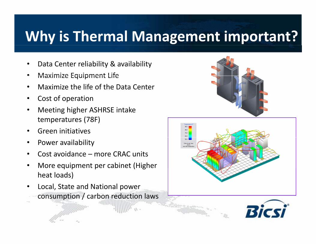
Why is Thermal Management important?• Data Center reliability & availability• Maximize Equipment Life• Maximize Equipment Life• Maximize the life of the Data Center• Cost of operation• Meeting higher ASHRSE intake
temperatures (78F)• Green initiatives• Power availability• Cost avoidance – more CRAC units• More equipment per cabinet (Higher q p p ( g
heat loads)• Local, State and National power
consumption / carbon reduction lawsp /
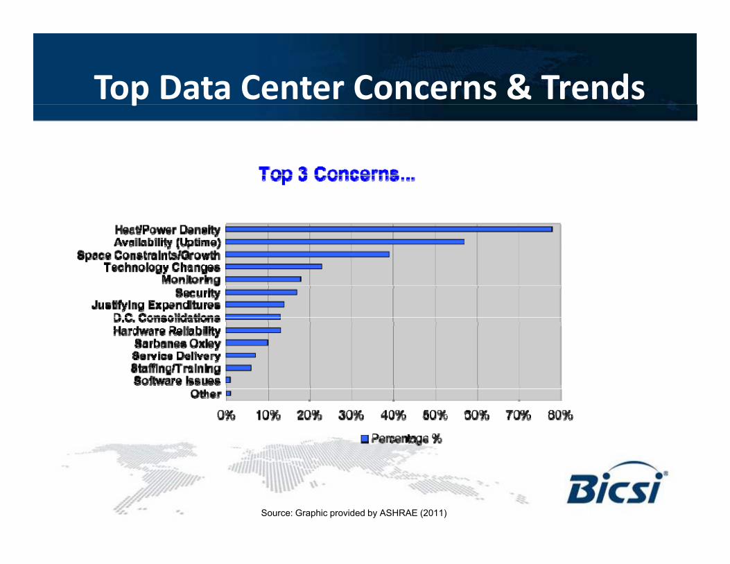
Top Data Center Concerns & Trendsp
Source: Graphic provided by ASHRAE (2011)
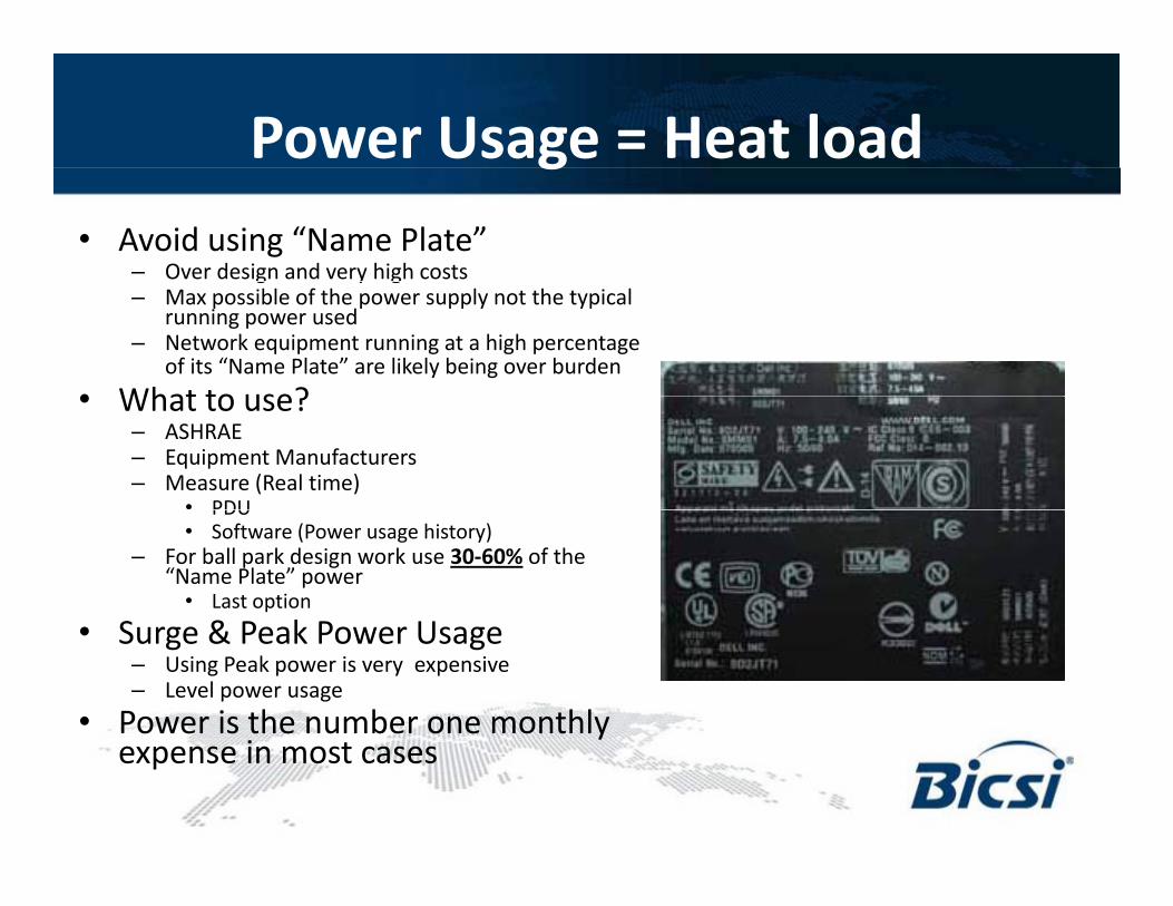
Power Usage = Heat loadg• Avoid using “Name Plate”
– Over design and very high costsg y g– Max possible of the power supply not the typical
running power used– Network equipment running at a high percentage
of its “Name Plate” are likely being over burden• What to use?• What to use?
– ASHRAE– Equipment Manufacturers– Measure (Real time)
• PDUPDU• Software (Power usage history)
– For ball park design work use 30-60% of the “Name Plate” power
• Last option
S & P k P U• Surge & Peak Power Usage– Using Peak power is very expensive– Level power usage
• Power is the number one monthly yexpense in most cases
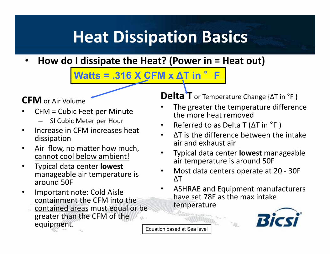
Heat Dissipation Basics• How do I dissipate the Heat? (Power in = Heat out)
Watts = .316 X CFM x ∆T in °F
Delta T or Temperature Change {ΔT in °F }• The greater the temperature difference
CFM or Air Volume• CFM = Cubic Feet per Minute g p
the more heat removed• Referred to as Delta T (ΔT in °F )• ΔT is the difference between the intake
air and exhaust air
• CFM = Cubic Feet per Minute– SI Cubic Meter per Hour
• Increase in CFM increases heat dissipation air and exhaust air
• Typical data center lowest manageable air temperature is around 50F
• Most data centers operate at 20 - 30F
• Air flow, no matter how much, cannot cool below ambient!
• Typical data center lowestmanageable air temperature is ΔT
• ASHRAE and Equipment manufacturers have set 78F as the max intake temperature
manageable air temperature is around 50F
• Important note: Cold Aisle containment the CFM into the contained areas must equal or be
Equation based at Sea level
temperaturecontained areas must equal or be greater than the CFM of the equipment.
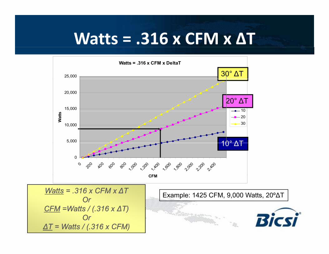
Watts = .316 x CFM x ΔTWatts = .316 x CFM x DeltaT
25,000 30° ∆T
15,000
20,000
10
20° ∆T
5,000
10,000
Wat
ts
102030
10° ∆T
0
0
200
400
600
800
1,000
1,200
1,400
1,600
1,800
2,000
2,200
2,400
CFM
10 ∆T
CFM
WattsWatts = .316 x CFM x ∆T= .316 x CFM x ∆TOrOr
CFMCFM W tt / ( 316W tt / ( 316 ∆T)∆T)
Example: 1425 CFM, 9,000 Watts, 20º∆T
CFMCFM =Watts / (.316 x =Watts / (.316 x ∆T)∆T)OrOr
∆T∆T = Watts / (.316 x CFM)= Watts / (.316 x CFM)
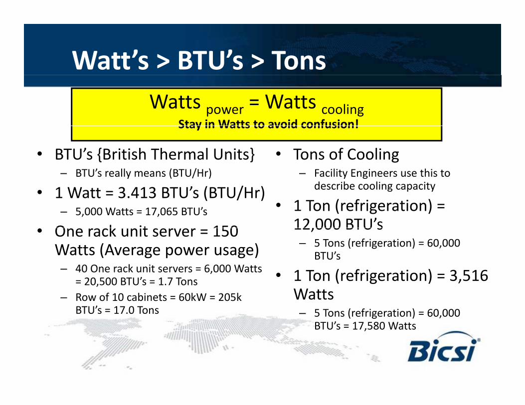
Watt’s > BTU’s > TonsWatts power = Watts cooling
Stay in Watts to avoid confusion!
• BTU’s {British Thermal Units}– BTU’s really means (BTU/Hr)
• Tons of Cooling– Facility Engineers use this to
Stay in Watts to avoid confusion!
y ( / )
• 1 Watt = 3.413 BTU’s (BTU/Hr)– 5,000 Watts = 17,065 BTU’s
O k it 150
y gdescribe cooling capacity
• 1 Ton (refrigeration) = 12,000 BTU’s• One rack unit server = 150
Watts (Average power usage)– 40 One rack unit servers = 6,000 Watts
20 500 BTU’ 1 7 T
12,000 BTU s– 5 Tons (refrigeration) = 60,000
BTU’s
• 1 Ton (refrigeration) = 3,516= 20,500 BTU’s = 1.7 Tons– Row of 10 cabinets = 60kW = 205k
BTU’s = 17.0 Tons
1 Ton (refrigeration) 3,516 Watts– 5 Tons (refrigeration) = 60,000
BTU’s = 17,580 Watts,
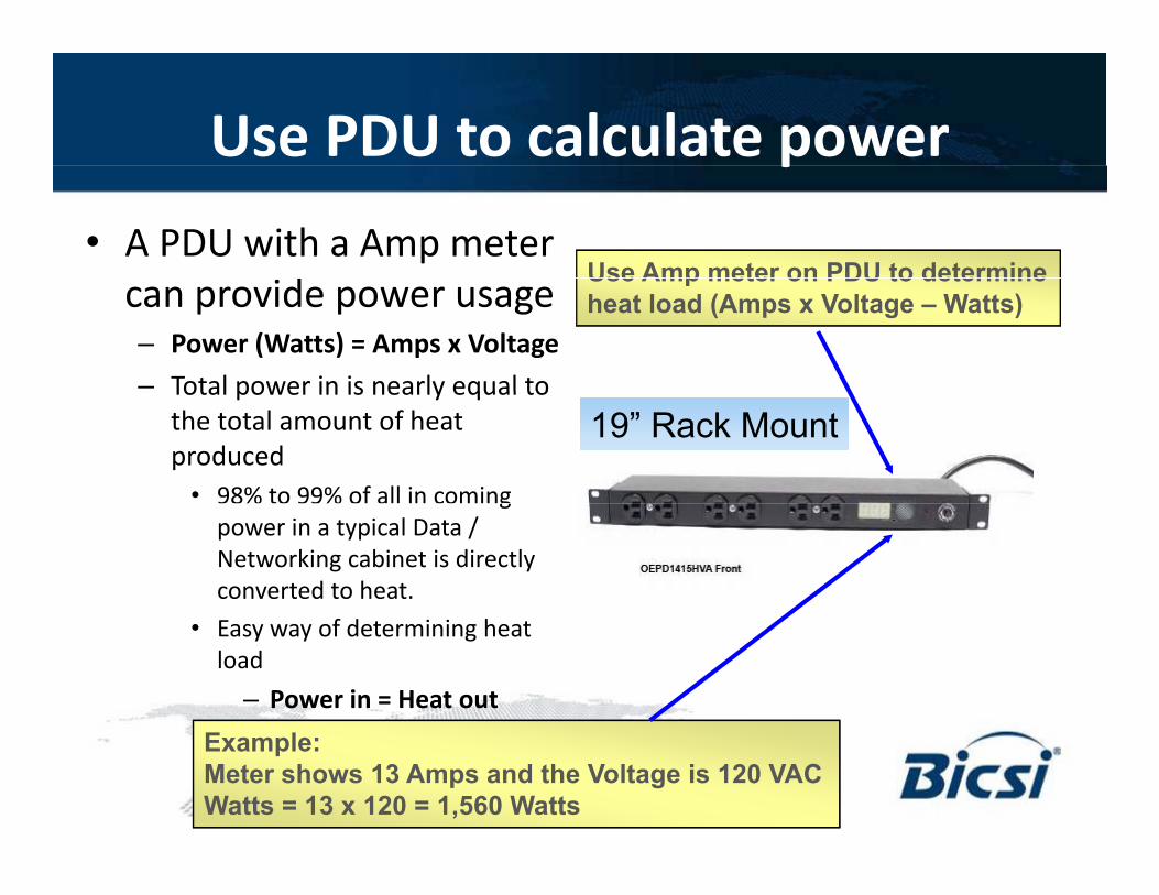
Use PDU to calculate power p• A PDU with a Amp meter
d Use Amp meter on PDU to determinecan provide power usage– Power (Watts) = Amps x Voltage– Total power in is nearly equal to
Use Amp meter on PDU to determineheat load (Amps x Voltage – Watts)
19” Rack Mount19” Rack MountTotal power in is nearly equal to the total amount of heat produced
• 98% to 99% of all in coming % % gpower in a typical Data / Networking cabinet is directly converted to heat.
• Easy way of determining heat load
– Power in = Heat outExample:Meter shows 13 Amps and the Voltage is 120 VACWatts = 13 x 120 = 1,560 Watts
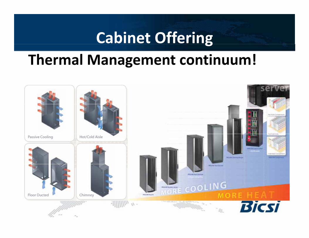
Cabinet OfferingThermal Management continuum!
g
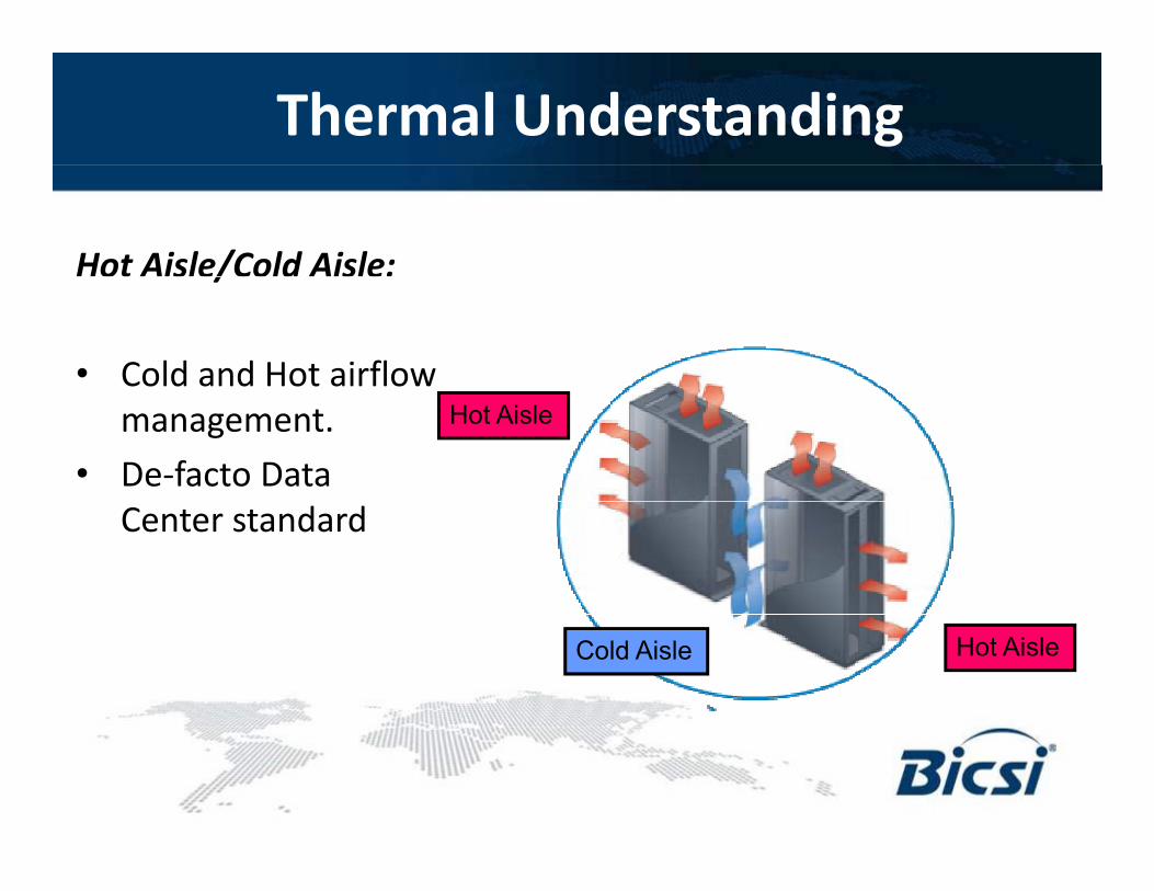
Thermal Understanding
Hot Aisle/Cold Aisle:ot s e/Co d s e
• Cold and Hot airflow management.
• De-facto Data
Hot Aisle
Center standard
Cold Aisle Hot Aisle
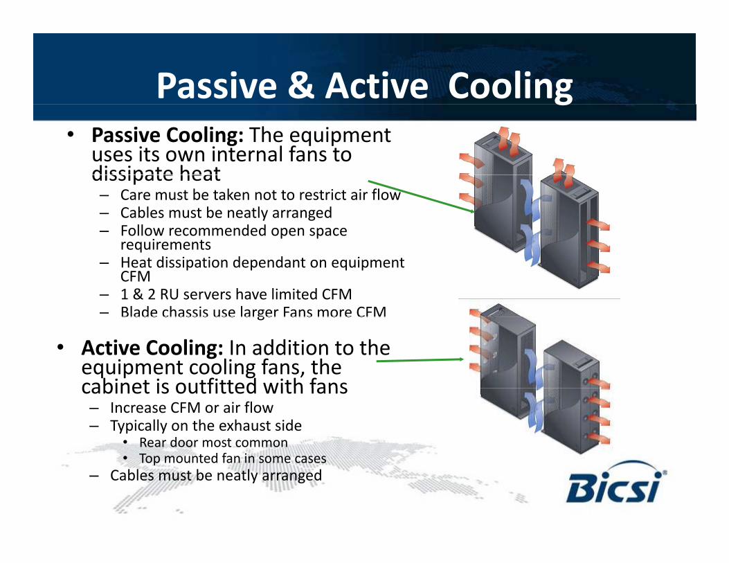
Passive & Active Coolingg• Passive Cooling: The equipment
uses its own internal fans to dissipate heatdissipate heat– Care must be taken not to restrict air flow– Cables must be neatly arranged– Follow recommended open space
requirementsrequirements– Heat dissipation dependant on equipment
CFM– 1 & 2 RU servers have limited CFM– Blade chassis use larger Fans more CFMBlade chassis use larger Fans more CFM
• Active Cooling: In addition to the equipment cooling fans, the cabinet is outfitted with fanscabinet is outfitted with fans– Increase CFM or air flow– Typically on the exhaust side
• Rear door most common• Top mounted fan in some cases• Top mounted fan in some cases
– Cables must be neatly arranged
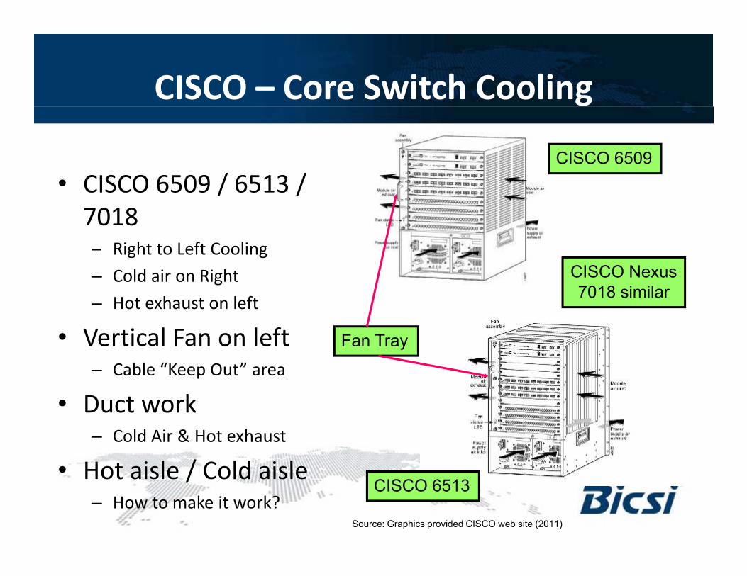
CISCO – Core Switch Cooling
CISCO 6509 / 6513 /CISCO 6509
• CISCO 6509 / 6513 / 7018– Right to Left CoolingRight to Left Cooling– Cold air on Right– Hot exhaust on left
CISCO Nexus7018 similar
• Vertical Fan on left– Cable “Keep Out” area
D t k
Fan Tray
• Duct work – Cold Air & Hot exhaust
• Hot aisle / Cold aisle• Hot aisle / Cold aisle– How to make it work?
CISCO 6513
Source: Graphics provided CISCO web site (2011)
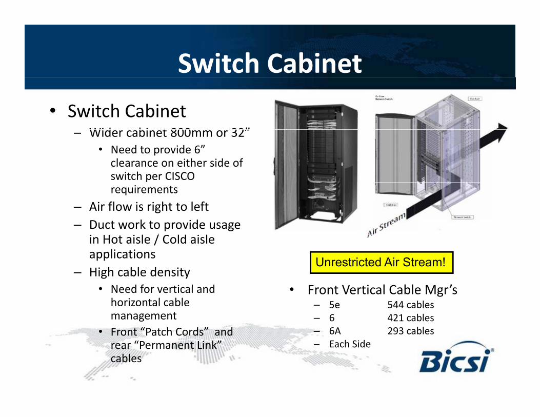
Switch Cabinet• Switch Cabinet
Wid bi t 800 32”– Wider cabinet 800mm or 32”• Need to provide 6”
clearance on either side of switch per CISCO requirements
– Air flow is right to left– Duct work to provide usage
i H i l / C ld i lin Hot aisle / Cold aisle applications
– High cable density• Need for vertical and
Unrestricted Air Stream!
• Front Vertical Cable Mgr’s• Need for vertical and horizontal cable management
• Front “Patch Cords” and
• Front Vertical Cable Mgr’s– 5e 544 cables– 6 421 cables– 6A 293 cables
h drear “Permanent Link” cables
– Each Side
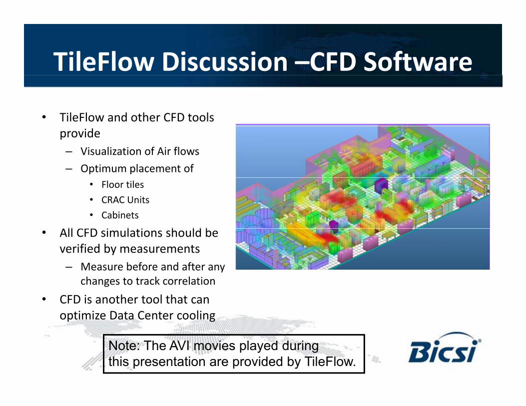
TileFlow Discussion –CFD Software
• TileFlow and other CFD tools provide– Visualization of Air flows– Optimum placement of
• Floor tiles• CRAC Units• Cabinets
All CFD i l i h ld b• All CFD simulations should be verified by measurements– Measure before and after any
changes to track correlationchanges to track correlation• CFD is another tool that can
optimize Data Center cooling
Note: The AVI movies played duringthis presentation are provided by TileFlow.
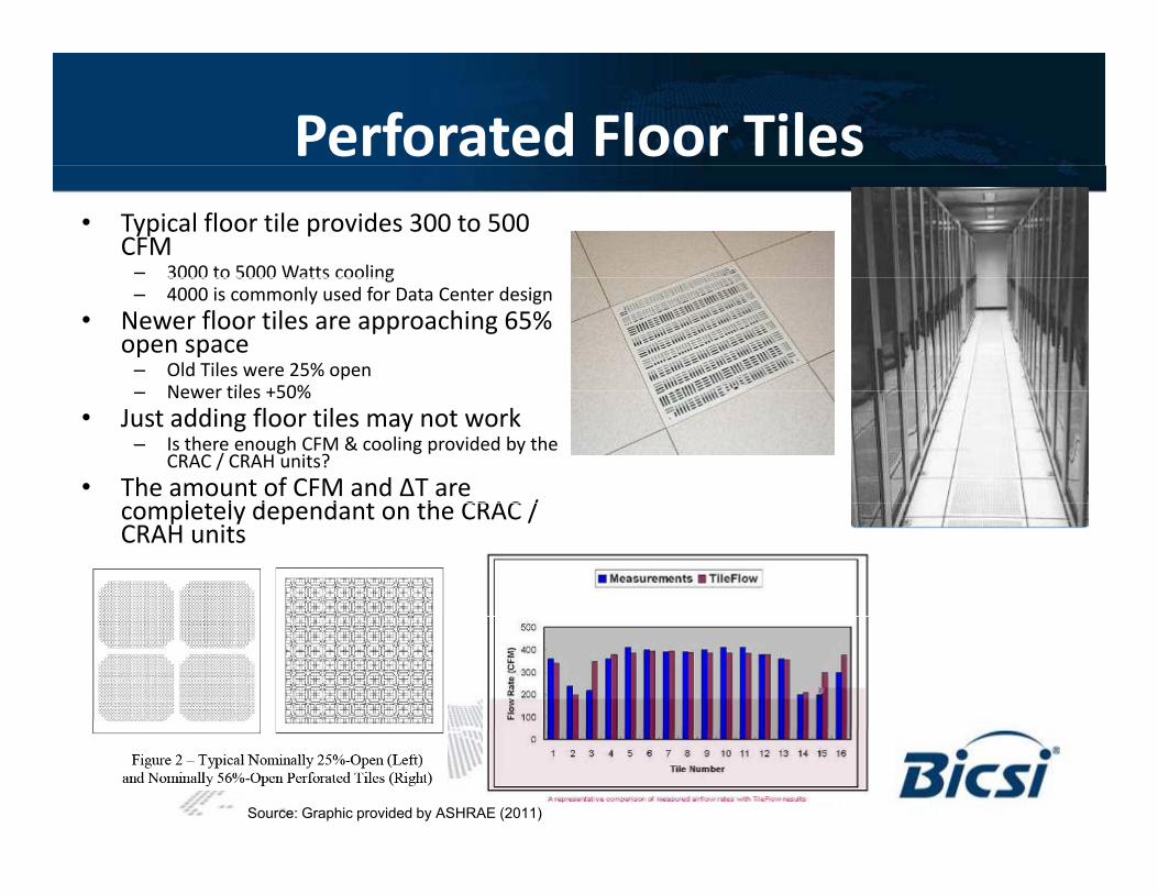
Perforated Floor Tiles• Typical floor tile provides 300 to 500
CFM– 3000 to 5000 Watts cooling3000 to 5000 Watts cooling– 4000 is commonly used for Data Center design
• Newer floor tiles are approaching 65% open space
– Old Tiles were 25% openNewer tiles +50%– Newer tiles +50%
• Just adding floor tiles may not work– Is there enough CFM & cooling provided by the
CRAC / CRAH units?• The amount of CFM and ΔT are
l t l d d t th CRAC /completely dependant on the CRAC / CRAH units
Source: Graphic provided by ASHRAE (2011)
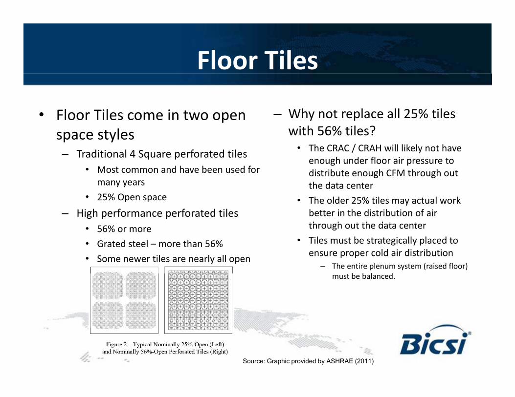
Floor Tiles
• Floor Tiles come in two open – Why not replace all 25% tiles space styles– Traditional 4 Square perforated tiles
• Most common and have been used for
with 56% tiles?• The CRAC / CRAH will likely not have
enough under floor air pressure to distribute enough CFM through out
many years• 25% Open space
– High performance perforated tiles
distribute enough CFM through out the data center
• The older 25% tiles may actual work better in the distribution of air th h t th d t t• 56% or more
• Grated steel – more than 56%• Some newer tiles are nearly all open
through out the data center• Tiles must be strategically placed to
ensure proper cold air distribution– The entire plenum system (raised floor)
b b l dmust be balanced.
Source: Graphic provided by ASHRAE (2011)

CFD Background - Floor Tilesg• Venturi effect
Tile to close to the CRAC Unit will result in down draft instead of cold air– Tile to close to the CRAC Unit will result in down draft instead of cold air flow upward.
• Too far away – little to no air flow– Rule of thumb – A CRAC unit can send out air to about 30 feet out
• Avoid raised floor less than 18”. Taller the raised floor the greater amount of cold air– Better air flows
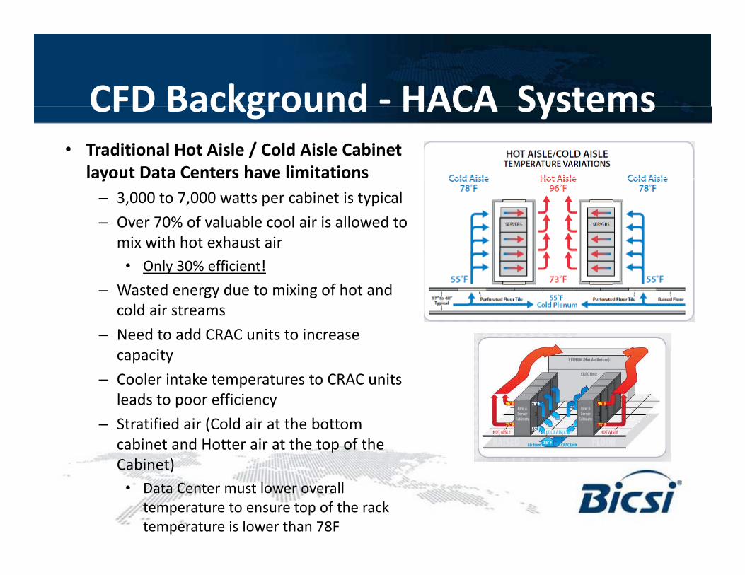
CFD Background - HACA SystemsCFD Background HACA Systems• Traditional Hot Aisle / Cold Aisle Cabinet
layout Data Centers have limitationsy– 3,000 to 7,000 watts per cabinet is typical– Over 70% of valuable cool air is allowed to
mix with hot exhaust air• Only 30% efficient!
– Wasted energy due to mixing of hot and cold air streams
– Need to add CRAC units to increase capacity
– Cooler intake temperatures to CRAC units l d t ffi ileads to poor efficiency
– Stratified air (Cold air at the bottom cabinet and Hotter air at the top of the Cabinet)Cabinet)• Data Center must lower overall
temperature to ensure top of the rack temperature is lower than 78F
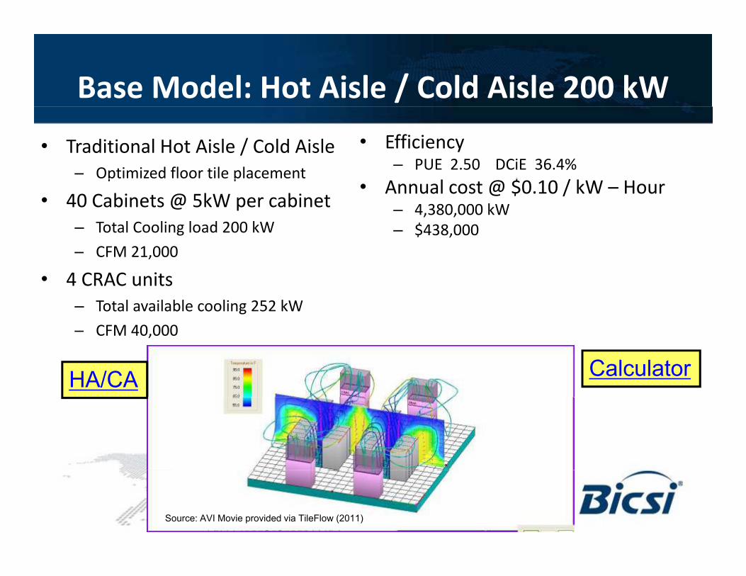
Base Model: Hot Aisle / Cold Aisle 200 kW
• Traditional Hot Aisle / Cold Aisle– Optimized floor tile placement
• Efficiency– PUE 2.50 DCiE 36.4%
$ /p p
• 40 Cabinets @ 5kW per cabinet– Total Cooling load 200 kW
CFM 21 000
• Annual cost @ $0.10 / kW – Hour– 4,380,000 kW– $438,000
– CFM 21,000
• 4 CRAC units– Total available cooling 252 kW– CFM 40,000
HA/CA Calculator
Source: AVI Movie provided via TileFlow (2011)
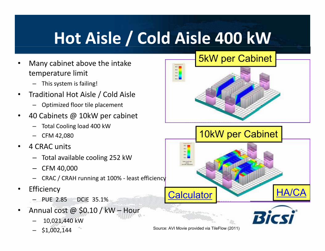
Hot Aisle / Cold Aisle 400 kW• Many cabinet above the intake
temperature limit
5kW per Cabinet
– This system is failing!
• Traditional Hot Aisle / Cold Aisle– Optimized floor tile placement
• 40 Cabinets @ 10kW per cabinet– Total Cooling load 400 kW– CFM 42,080 10kW per Cabinet
• 4 CRAC units– Total available cooling 252 kW– CFM 40,000 – CRAC / CRAH running at 100% - least efficiency
• Efficiency– PUE 2.85 DCiE 35.1%
HA/CACalculator• Annual cost @ $0.10 / kW – Hour
– 10,021,440 kW– $1,002,144 Source: AVI Movie provided via TileFlow (2011)
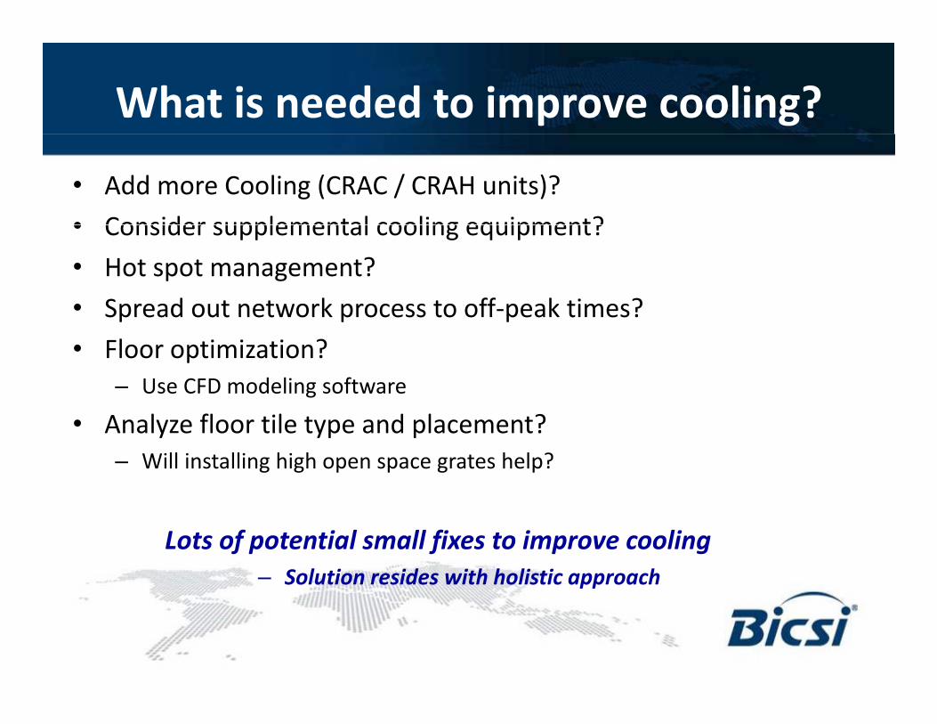
What is needed to improve cooling?
• Add more Cooling (CRAC / CRAH units)?• Consider supplemental cooling equipment?• Consider supplemental cooling equipment?• Hot spot management?• Spread out network process to off-peak times?Spread out network process to off peak times?• Floor optimization?
– Use CFD modeling software
• Analyze floor tile type and placement?– Will installing high open space grates help?
Lots of potential small fixes to improve cooling– Solution resides with holistic approach
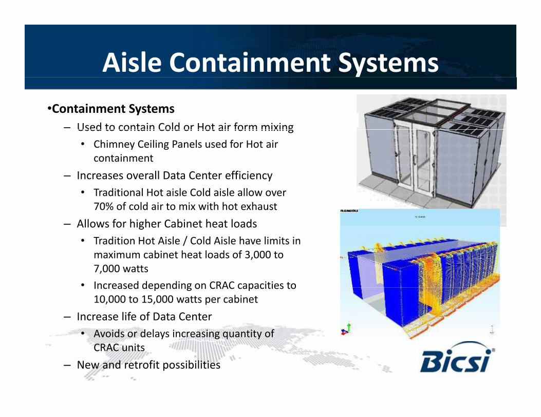
Aisle Containment Systems•Containment Systems
– Used to contain Cold or Hot air form mixingUsed to contain Cold or Hot air form mixing• Chimney Ceiling Panels used for Hot air
containment– Increases overall Data Center efficiency
• Traditional Hot aisle Cold aisle allow over 70% of cold air to mix with hot exhaust
– Allows for higher Cabinet heat loads• Tradition Hot Aisle / Cold Aisle have limits in
maximum cabinet heat loads of 3,000 to 7,000 watts
• Increased depending on CRAC capacities toIncreased depending on CRAC capacities to 10,000 to 15,000 watts per cabinet
– Increase life of Data Center • Avoids or delays increasing quantity of
CRAC units– New and retrofit possibilities
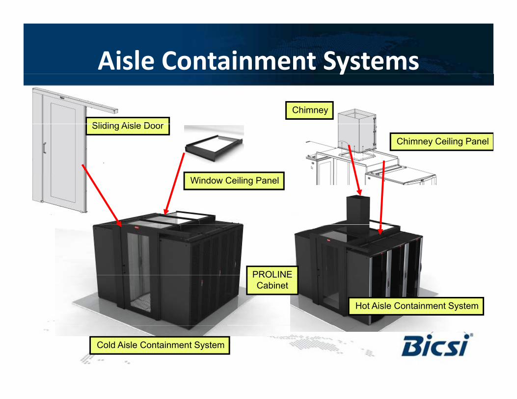
Aisle Containment Systemsy
Sliding Aisle Door
Chimney
Sliding Aisle Door
Chimney Ceiling Panel
Window Ceiling Panel
PROLINE
Hot Aisle Containment System
PROLINECabinet
Cold Aisle Containment System
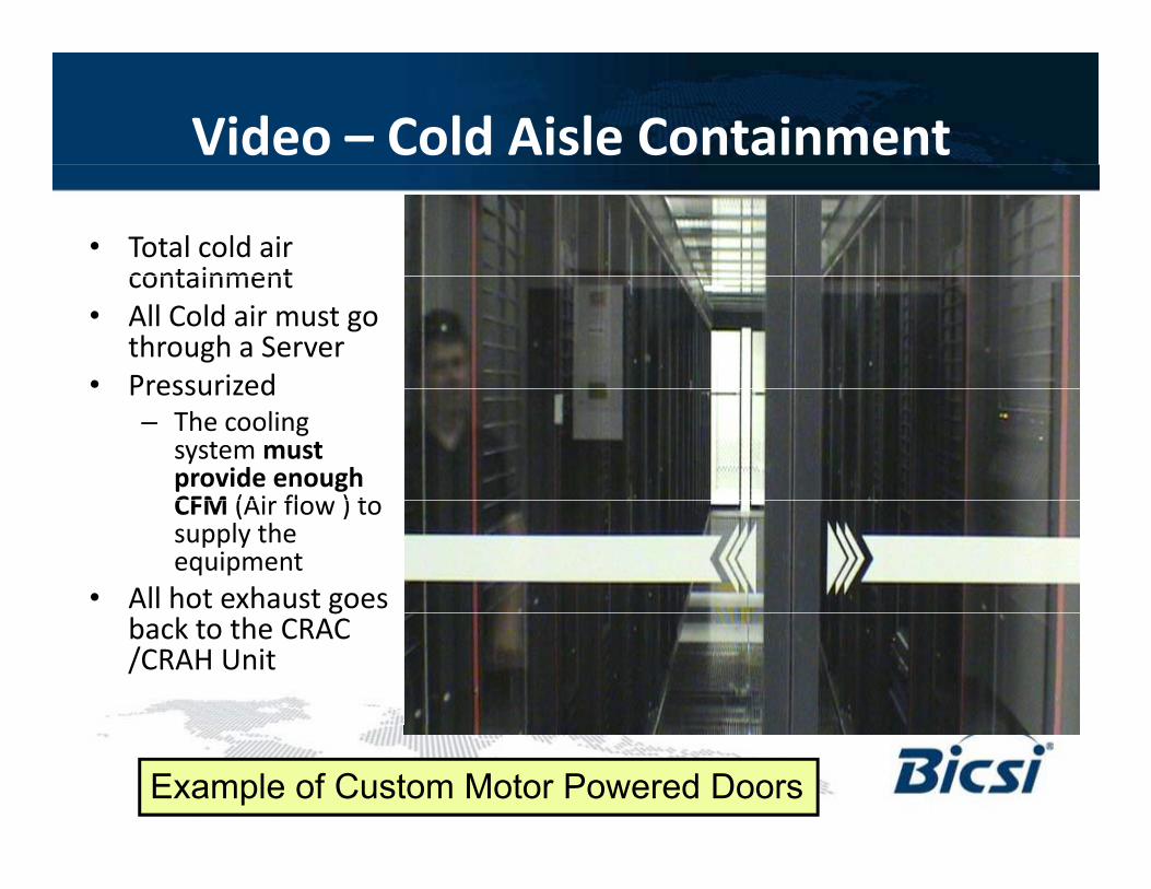
Video – Cold Aisle Containment
• Total cold air containmentcontainment
• All Cold air must go through a Server
• PressurizedPressurized– The cooling
system must provide enough CFM (Air flo ) toCFM (Air flow ) to supply the equipment
• All hot exhaust goes gback to the CRAC /CRAH Unit
Example of Custom Motor Powered Doors
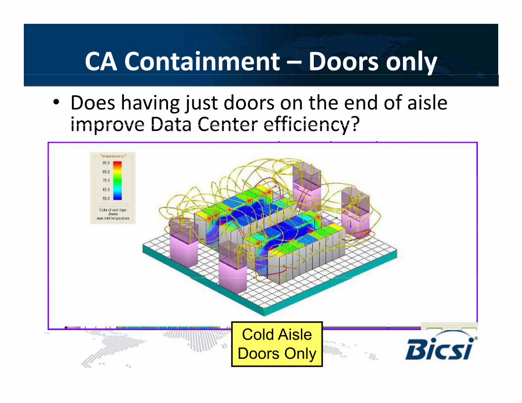
CA Containment – Doors onlyy• Does having just doors on the end of aisle
improve Data Center efficiency?improve Data Center efficiency?– No improvement – worse than with out doors– Note more hot exhaust wrap around the top of the p p
cabinet into cold aisles
C ld Ai lCold AisleDoors Only
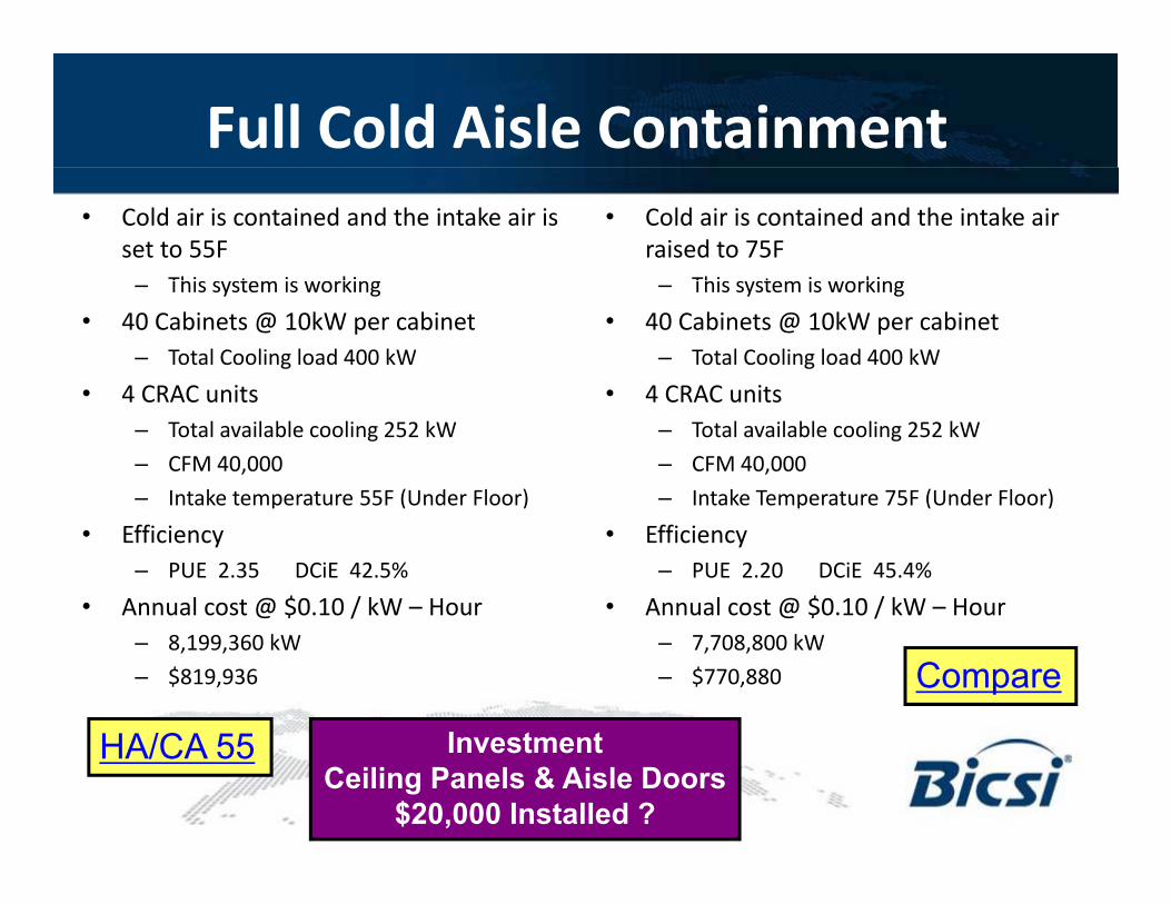
Full Cold Aisle Containment• Cold air is contained and the intake air is
set to 55FThis system is working
• Cold air is contained and the intake air raised to 75F
This system is working– This system is working• 40 Cabinets @ 10kW per cabinet
– Total Cooling load 400 kW• 4 CRAC units
– This system is working• 40 Cabinets @ 10kW per cabinet
– Total Cooling load 400 kW• 4 CRAC units• 4 CRAC units
– Total available cooling 252 kW– CFM 40,000 – Intake temperature 55F (Under Floor)
• 4 CRAC units– Total available cooling 252 kW– CFM 40,000 – Intake Temperature 75F (Under Floor)p
• Efficiency– PUE 2.35 DCiE 42.5%
• Annual cost @ $0.10 / kW – Hour
p• Efficiency
– PUE 2.20 DCiE 45.4%• Annual cost @ $0.10 / kW – Hour
– 8,199,360 kW– $819,936
– 7,708,800 kW– $770,880
HA/CA 55
Compare
In estmentHA/CA 55 InvestmentCeiling Panels & Aisle Doors
$20,000 Installed ?
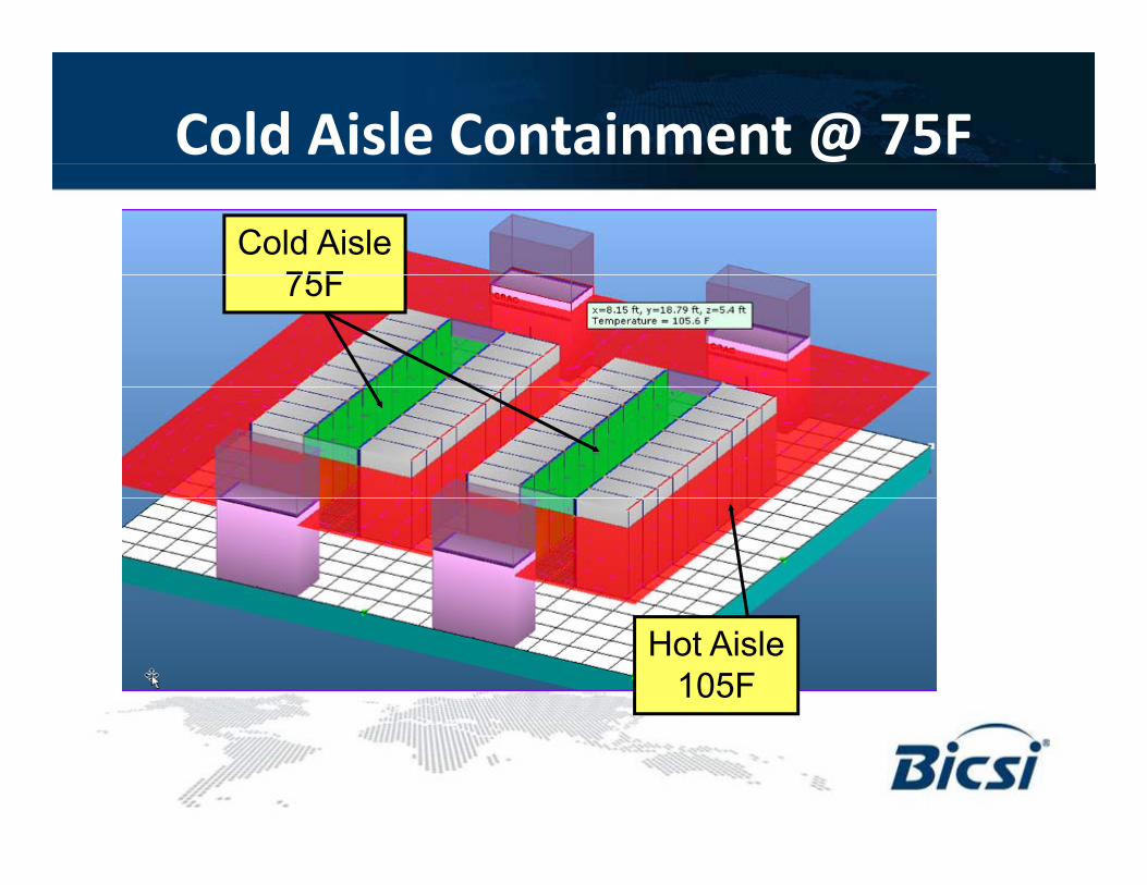
Cold Aisle Containment @ 75FCold Aisle
75F75F
Hot Aisle105F
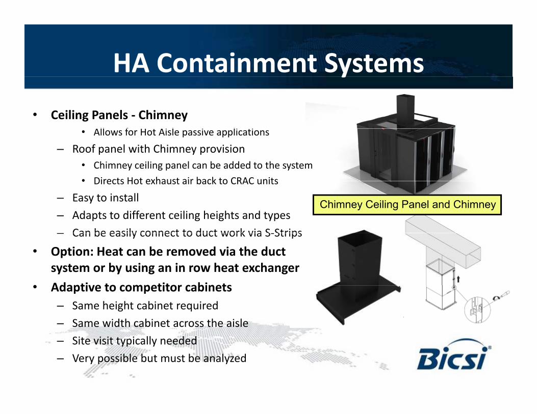
HA Containment Systemsy• Ceiling Panels - Chimney
All f H Ai l i li i• Allows for Hot Aisle passive applications– Roof panel with Chimney provision
• Chimney ceiling panel can be added to the system• Directs Hot exhaust air back to CRAC units• Directs Hot exhaust air back to CRAC units
– Easy to install– Adapts to different ceiling heights and types– Can be easily connect to duct work via S-Strips
Chimney Ceiling Panel and Chimney
– Can be easily connect to duct work via S-Strips• Option: Heat can be removed via the duct
system or by using an in row heat exchanger• Adaptive to competitor cabinets• Adaptive to competitor cabinets
– Same height cabinet required– Same width cabinet across the aisle
Sit i it t i ll d d– Site visit typically needed– Very possible but must be analyzed
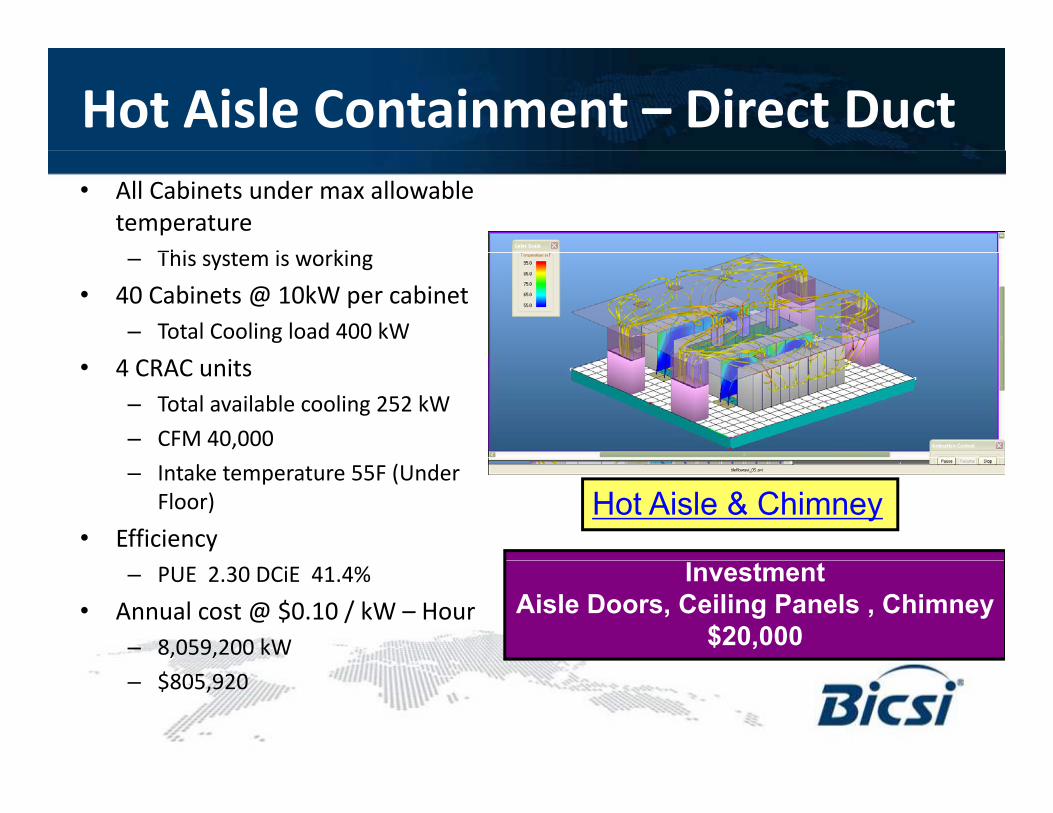
Hot Aisle Containment – Direct Duct• All Cabinets under max allowable
temperatureThi t i ki– This system is working
• 40 Cabinets @ 10kW per cabinet– Total Cooling load 400 kW
• 4 CRAC units– Total available cooling 252 kW– CFM 40,000– Intake temperature 55F (Under
Floor)• Efficiency
Hot Aisle & Chimney
– PUE 2.30 DCiE 41.4%• Annual cost @ $0.10 / kW – Hour
– 8,059,200 kW
InvestmentAisle Doors, Ceiling Panels , Chimney
$20,000– $805,920
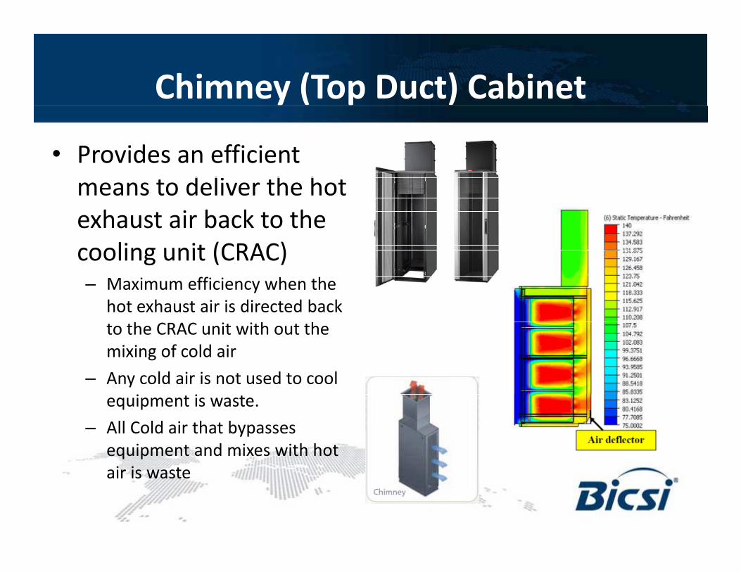
Chimney (Top Duct) Cabinet
• Provides an efficient d li h hmeans to deliver the hot
exhaust air back to the cooling unit (CRAC)cooling unit (CRAC)– Maximum efficiency when the
hot exhaust air is directed back h h hto the CRAC unit with out the
mixing of cold air– Any cold air is not used to cool
i iequipment is waste.– All Cold air that bypasses
equipment and mixes with hot i iair is waste
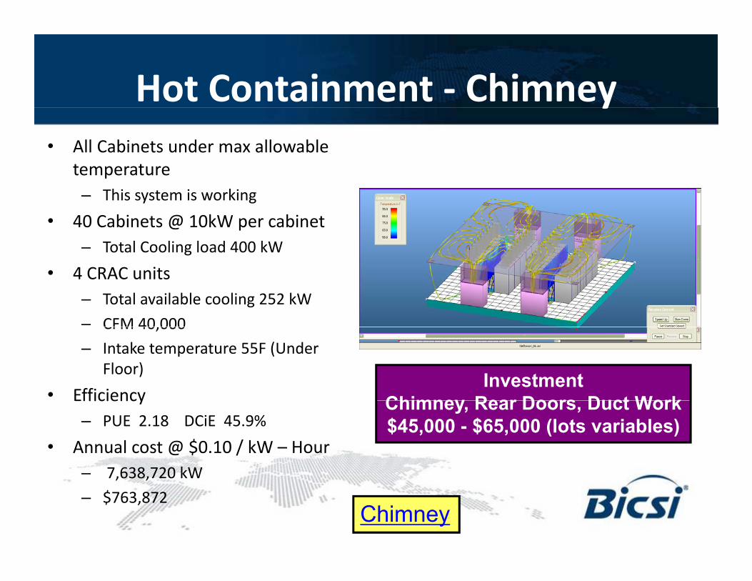
Hot Containment - Chimneyy• All Cabinets under max allowable
temperature– This system is working
• 40 Cabinets @ 10kW per cabinet– Total Cooling load 400 kWg
• 4 CRAC units– Total available cooling 252 kW– CFM 40,000CFM 40,000 – Intake temperature 55F (Under
Floor)• Efficiency
InvestmentChimney Rear Doors Duct WorkEfficiency
– PUE 2.18 DCiE 45.9%• Annual cost @ $0.10 / kW – Hour
– 7 638 720 kW
Chimney, Rear Doors, Duct Work$45,000 - $65,000 (lots variables)
– 7,638,720 kW– $763,872
Chimney
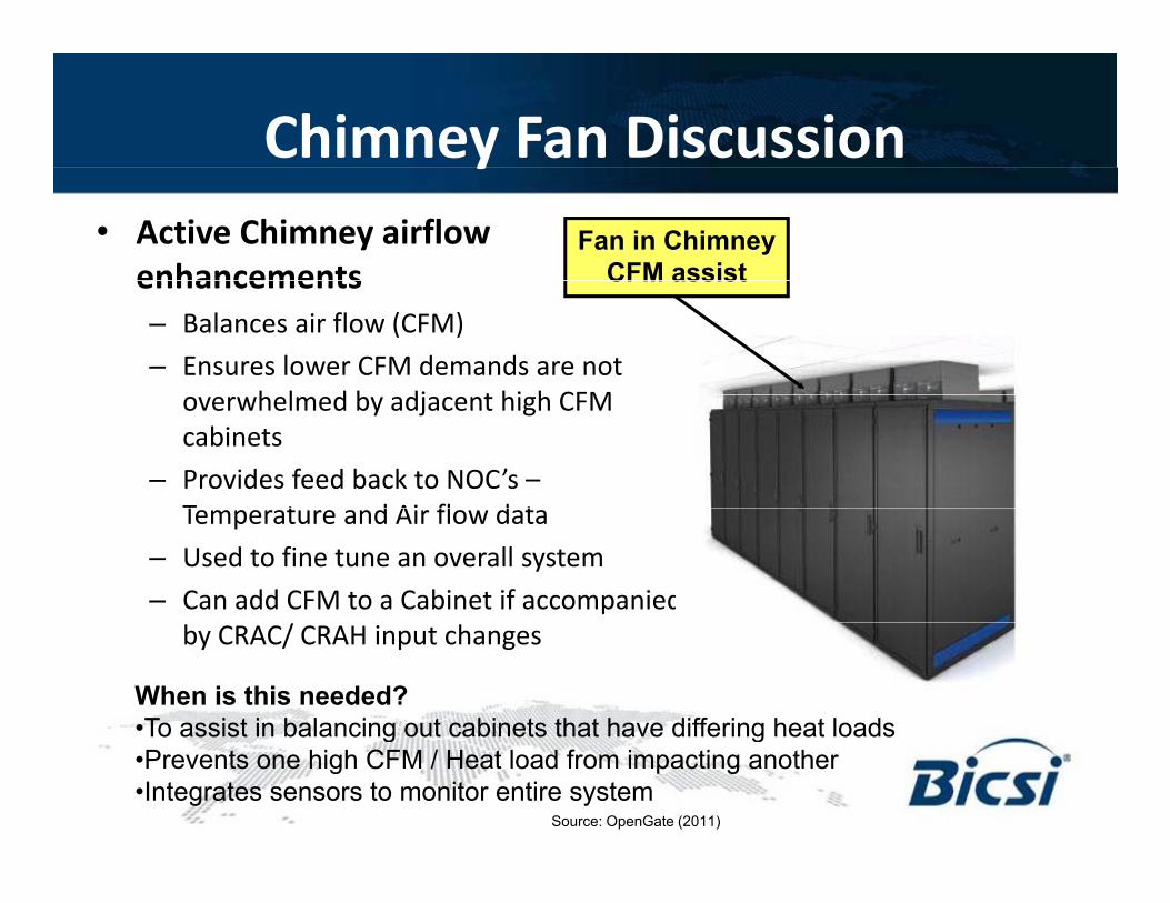
Chimney Fan Discussiony• Active Chimney airflow
enhancementsFan in Chimney
CFM assistenhancements– Balances air flow (CFM)– Ensures lower CFM demands are not
h l d b dj t hi h CFM
CFM assist
overwhelmed by adjacent high CFM cabinets
– Provides feed back to NOC’s –T t d Ai fl d tTemperature and Air flow data
– Used to fine tune an overall system– Can add CFM to a Cabinet if accompanied
by CRAC/ CRAH input changes
When is this needed?•To assist in balancing out cabinets that have differing heat loadsTo assist in balancing out cabinets that have differing heat loads•Prevents one high CFM / Heat load from impacting another•Integrates sensors to monitor entire system
Source: OpenGate (2011)
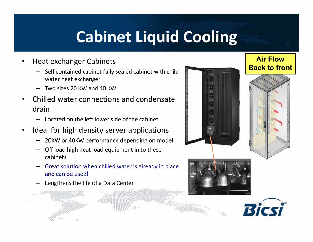
Cabinet Liquid Coolingq g• Heat exchanger Cabinets
– Self contained cabinet fully sealed cabinet with child
Air FlowBack to front
water heat exchanger– Two sizes 20 KW and 40 KW
• Chilled water connections and condensate drain
– Located on the left lower side of the cabinet
• Ideal for high density server applications– 20KW or 40KW performance depending on model– Off load high heat load equipment in to these
cabinets– Great solution when chilled water is already in placeGreat solution when chilled water is already in place
and can be used!– Lengthens the life of a Data Center
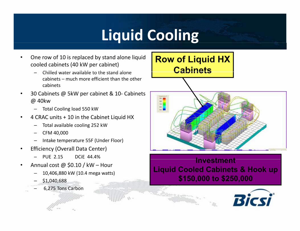
Liquid Coolingq g• One row of 10 is replaced by stand alone liquid
cooled cabinets (40 kW per cabinet)Chilled water available to the stand alone
Row of Liquid HXCabinets– Chilled water available to the stand alone
cabinets – much more efficient than the other cabinets
• 30 Cabinets @ 5kW per cabinet & 10- Cabinets @ 40kw
Cabinets
@ 40kw– Total Cooling load 550 kW
• 4 CRAC units + 10 in the Cabinet Liquid HX– Total available cooling 252 kW– CFM 40,000 – Intake temperature 55F (Under Floor)
• Efficiency (Overall Data Center)– PUE 2.15 DCiE 44.4% Investment
• Annual cost @ $0.10 / kW – Hour– 10,406,880 kW (10.4 mega watts)– $1,040,688– 6 275 Tons Carbon
InvestmentLiquid Cooled Cabinets & Hook up
$150,000 to $250,000– 6,275 Tons Carbon
Types of “Supplemental” Coolingyp pp g• Rear Door Cooling
– Mounted on rear door of cabinet– Condition hot air & return it to the room at a more suitable temperature for struggling CRAC unitsCondition hot air & return it to the room at a more suitable temperature for struggling CRAC units– Installed on cabinets – no floor space required – Most solutions require a chilled water source and a connection to a remote chiller system
• Overhead Heat Cooling– Mounted either above cabinet rows (aisles) or directly on top of the cabinets– Complements existing hot aisle, cold aisle arrangement– Pulls in hot air as it rises from the hot aisle, conditions it, and returns it to the cold aisle– Most solutions require a refrigerant pump and a remote heat rejection source: either a chiller or condenser,
depending on the infrastructure available• In-Row Cooling• In-Row Cooling
– Mounted between two cabinets within a row – one or more can be installed per row – Cabinet level cooling – removes and neutralizes hot air from cabinets – Requires a chilled water source and a connection to a remote chiller system, some are available in refrigerant
(requires a pump, remote heat rejection source and a condenser); some glycol solutions available• Cabinet mounted air/water heat exchanger
– Cabinet mounted (either vertical or horizontal) – Requires chilled water source and a connection to remote chiller system– Typically a closed loop cooling solution (self contained)
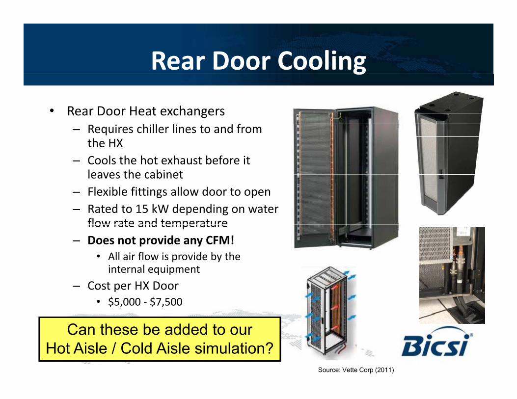
Rear Door Cooling g
• Rear Door Heat exchangersh ll l f– Requires chiller lines to and from
the HX– Cools the hot exhaust before it
leaves the cabinetleaves the cabinet– Flexible fittings allow door to open– Rated to 15 kW depending on water
flow rate and temperatureflow rate and temperature– Does not provide any CFM!
• All air flow is provide by the internal equipment
– Cost per HX Door• $5,000 - $7,500
C th b dd d tCan these be added to ourHot Aisle / Cold Aisle simulation?
Source: Vette Corp (2011)
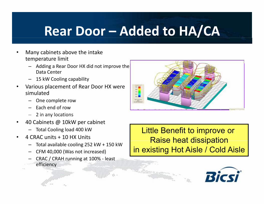
Rear Door – Added to HA/CA• Many cabinets above the intake
temperature limit– Adding a Rear Door HX did not improve the
Data Center– 15 kW Cooling capability
• Various placement of Rear Door HX were psimulated
– One complete row– Each end of row– 2 in any locations– 2 in any locations
• 40 Cabinets @ 10kW per cabinet– Total Cooling load 400 kW
• 4 CRAC units + 10 HX UnitsLittle Benefit to improve or
Raise heat dissipation– Total available cooling 252 kW + 150 kW– CFM 40,000 (Was not increased)– CRAC / CRAH running at 100% - least
efficiency
Raise heat dissipationin existing Hot Aisle / Cold Aisle
y
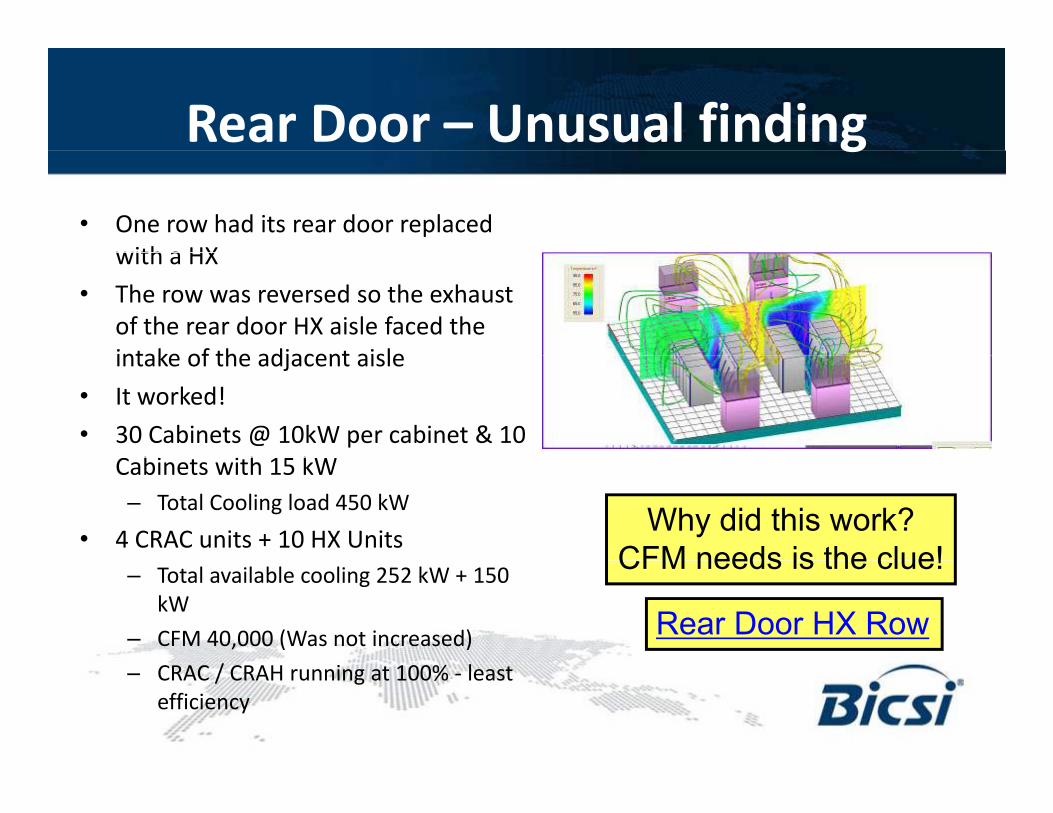
Rear Door – Unusual findingg• One row had its rear door replaced
with a HXwith a HX• The row was reversed so the exhaust
of the rear door HX aisle faced the intake of the adjacent aisleintake of the adjacent aisle
• It worked!• 30 Cabinets @ 10kW per cabinet & 10
C bi i h 15 kWCabinets with 15 kW– Total Cooling load 450 kW
• 4 CRAC units + 10 HX UnitsWhy did this work?
CFM needs is the clue!– Total available cooling 252 kW + 150 kW
– CFM 40,000 (Was not increased) Rear Door HX Row
CFM needs is the clue!
– CRAC / CRAH running at 100% - least efficiency
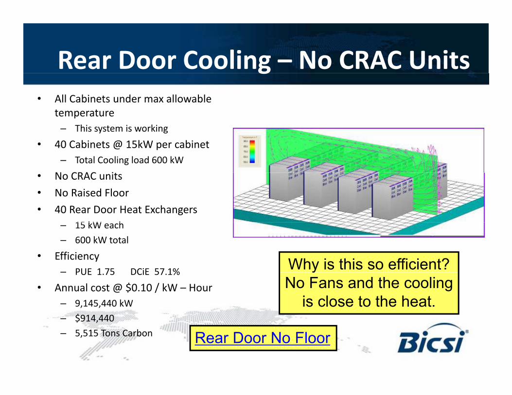
Rear Door Cooling – No CRAC Unitsg• All Cabinets under max allowable
temperature– This system is working
• 40 Cabinets @ 15kW per cabinet– Total Cooling load 600 kW
N CRAC i• No CRAC units• No Raised Floor• 40 Rear Door Heat Exchangers
15 kW h– 15 kW each– 600 kW total
• Efficiency– PUE 1 75 DCiE 57 1% Why is this so efficient?– PUE 1.75 DCiE 57.1%
• Annual cost @ $0.10 / kW – Hour– 9,145,440 kW– $914,440
yNo Fans and the cooling
is close to the heat.$ ,
– 5,515 Tons Carbon Rear Door No Floor
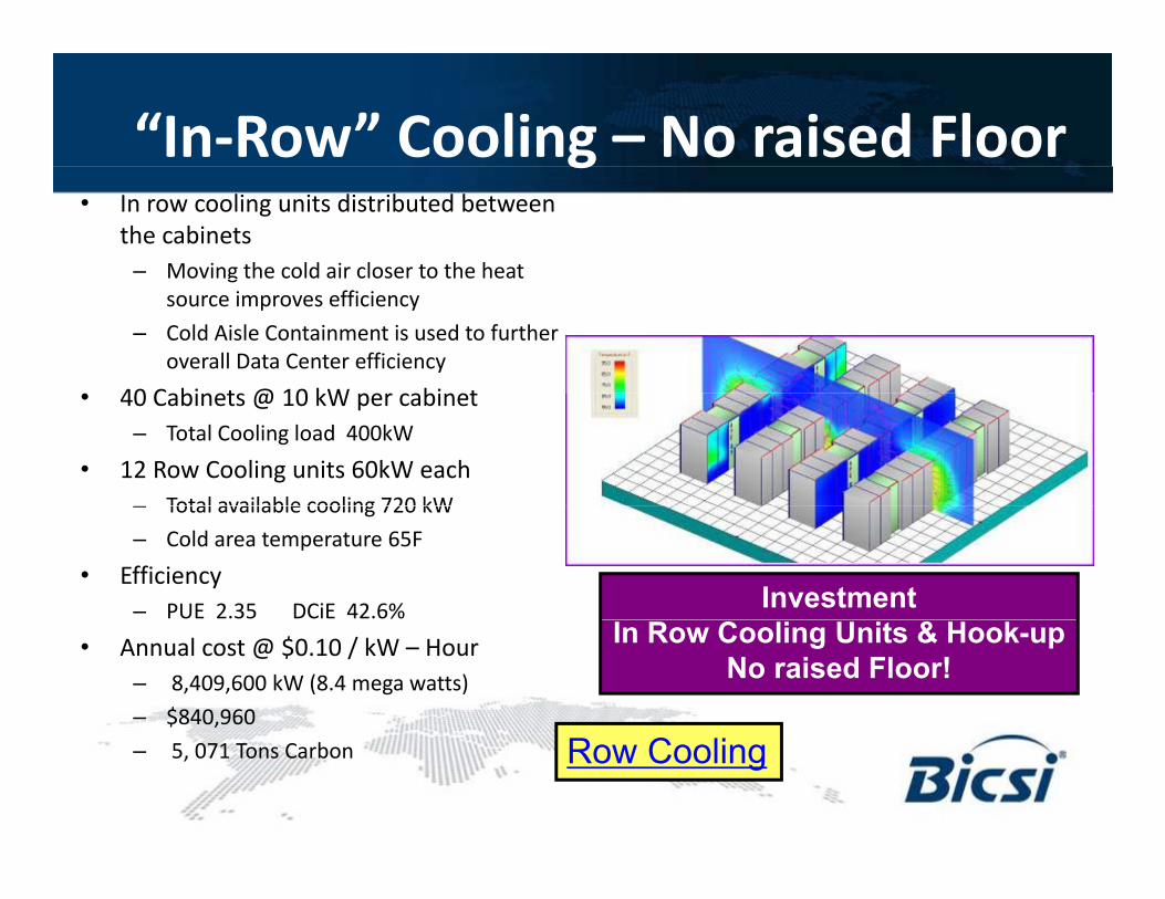
“In-Row” Cooling – No raised Floorg• In row cooling units distributed between
the cabinets– Moving the cold air closer to the heat g
source improves efficiency– Cold Aisle Containment is used to further
overall Data Center efficiency40 C bi t @ 10 kW bi t• 40 Cabinets @ 10 kW per cabinet
– Total Cooling load 400kW• 12 Row Cooling units 60kW each
– Total available cooling 720 kW– Total available cooling 720 kW– Cold area temperature 65F
• Efficiency– PUE 2.35 DCiE 42.6% Investment
• Annual cost @ $0.10 / kW – Hour– 8,409,600 kW (8.4 mega watts)– $840,960
In Row Cooling Units & Hook-upNo raised Floor!
– 5, 071 Tons Carbon Row Cooling
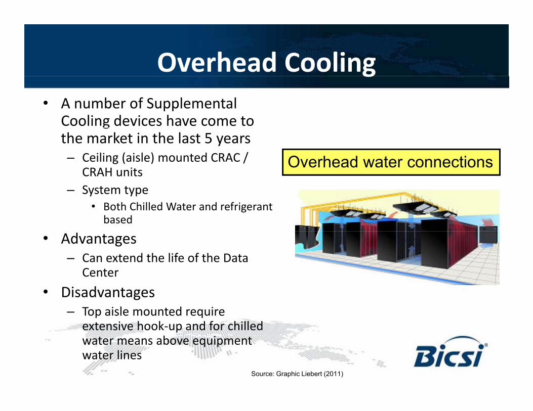
Overhead Coolingg• A number of Supplemental
Cooling devices have come to gthe market in the last 5 years– Ceiling (aisle) mounted CRAC /
CRAH unitsOverhead water connections
– System type• Both Chilled Water and refrigerant
based
• Advantages– Can extend the life of the Data
Center• Disadvantages
– Top aisle mounted require extensive hook-up and for chilled water means above equipment water lines
Source: Graphic Liebert (2011)
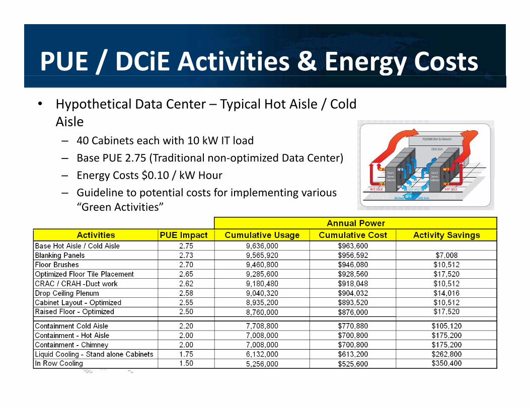
PUE / DCiE Activities & Energy Costs• Hypothetical Data Center – Typical Hot Aisle / Cold
Aisle– 40 Cabinets each with 10 kW IT load– Base PUE 2.75 (Traditional non-optimized Data Center)– Energy Costs $0.10 / kW HourEnergy Costs $0.10 / kW Hour– Guideline to potential costs for implementing various
“Green Activities”
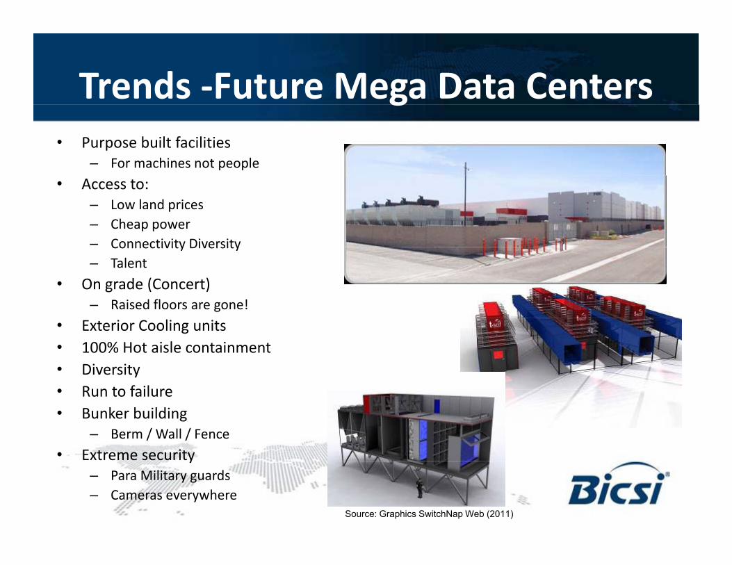
Trends -Future Mega Data Centersg• Purpose built facilities
– For machines not people• Access to:
– Low land prices– Cheap power– Connectivity DiversityConnectivity Diversity– Talent
• On grade (Concert)– Raised floors are gone!
• Exterior Cooling units• 100% Hot aisle containment• Diversity• Run to failure• Run to failure• Bunker building
– Berm / Wall / Fence• Extreme securityy
– Para Military guards– Cameras everywhere
Source: Graphics SwitchNap Web (2011)
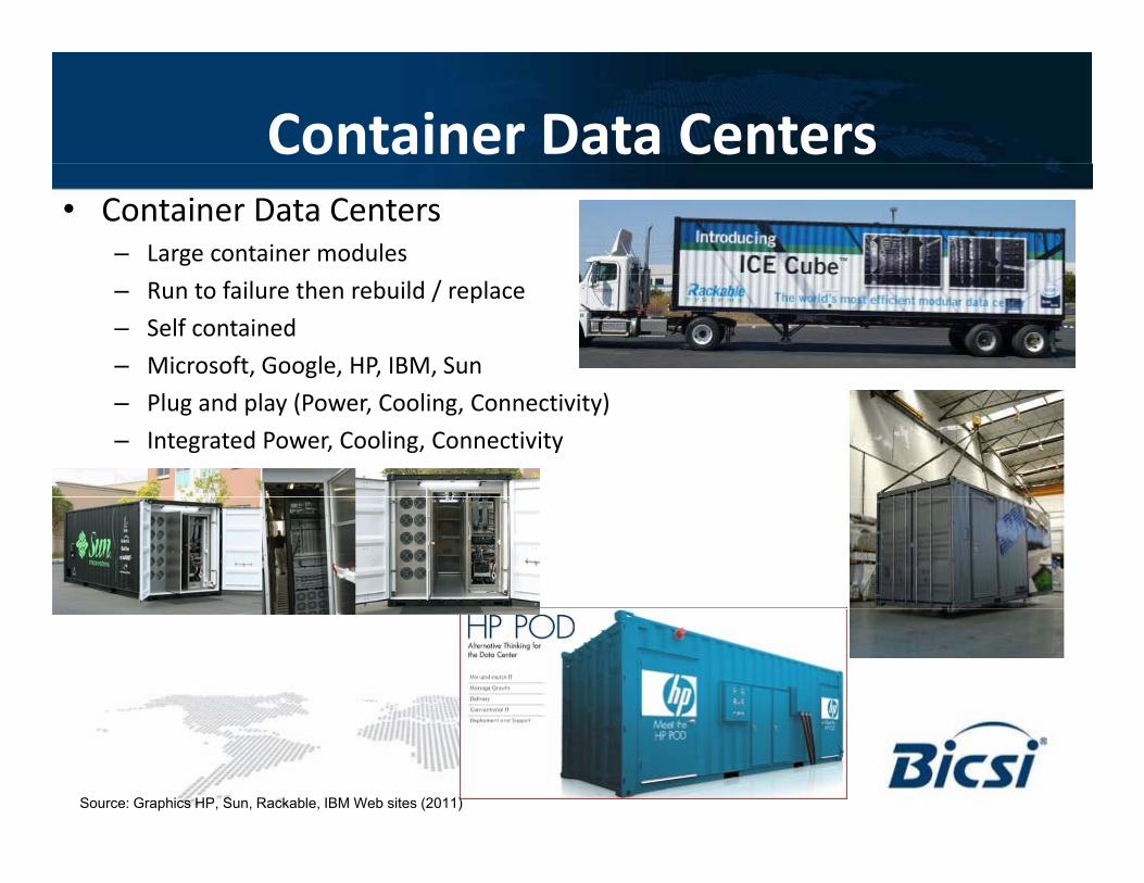
Container Data Centers• Container Data Centers
– Large container modules– Run to failure then rebuild / replace– Self contained– Microsoft, Google, HP, IBM, Sun– Plug and play (Power, Cooling, Connectivity)– Integrated Power, Cooling, Connectivity
Source: Graphics HP, Sun, Rackable, IBM Web sites (2011)
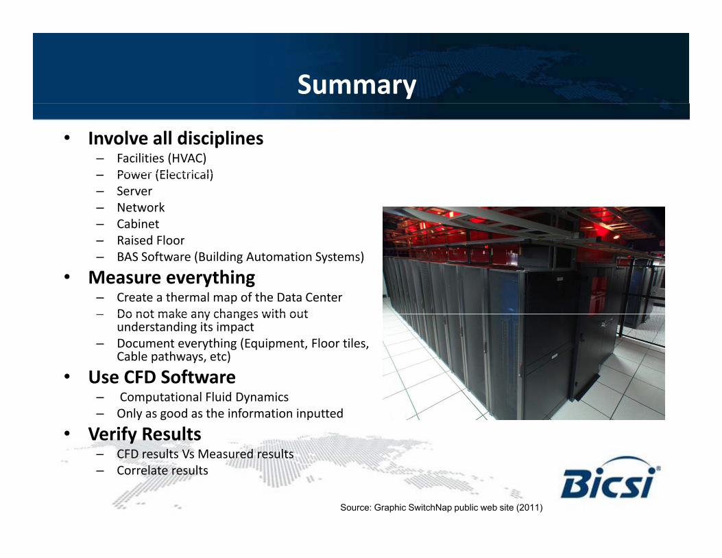
Summary
• Involve all disciplines– Facilities (HVAC)
Power (Electrical)– Power (Electrical)– Server– Network– Cabinet– Raised FloorRaised Floor– BAS Software (Building Automation Systems)
• Measure everything– Create a thermal map of the Data Center– Do not make any changes with out– Do not make any changes with out
understanding its impact– Document everything (Equipment, Floor tiles,
Cable pathways, etc)
• Use CFD Software– Computational Fluid Dynamics – Only as good as the information inputted
• Verify Results– CFD results Vs Measured resultsCFD results Vs Measured results– Correlate results
Source: Graphic SwitchNap public web site (2011)
Thank You!
• Questions?B i L M di k RCDD– Brian L. Mordick RCDD
– Pentair Technical Products (Hoffman)– [email protected]

![Home [] · 2021. 2. 24. · samsung samsung samsung samsung samsung advance advance advance advance advance advance advance advance advance advance 223sw 2233sw 2233sw 2233sw 933sn](https://img.pdfslide.net/doc/110x75/613cd1974c23507cb6359ff0/home-2021-2-24-samsung-samsung-samsung-samsung-samsung-advance-advance.jpg)