Embed Size (px)
Citation preview

© 200● The Institute of Electrical Engineers of Japan. 1
NISSAN e-POWER: 100 % Electric Drive and Its Powertrain Control
Kantaro Yoshimoto*a) Member, Tomoyuki Hanyu** Non-member
(Manuscript received Jan. 00, 20XX, revised May 00, 20XX)
Nissan has developed a 100 % electrified powertrain system called e-POWER, which exhibits key features such as quick response,
smooth acceleration, smooth deceleration, and quietness. The quick response and smooth acceleration can be achieved owing to
the 100 % electric motor drive and control strategy that has been adopted from the Nissan LEAF electric vehicle and improved
further. The quietness was designed and controlled using power generation control and engine speed control. A driving mode called
the e-POWER drive mode was developed using 100 % electric deceleration to achieve smooth and efficient deceleration with
linearity and controllability.
Keywords : hybrid electric vehicle, electric vehicle, powertrain control, traction control, power generation control
1. Introduction
"Vehicle electrification" is not only a technology of powertrain,
but also the key technology for a major turning point that occurs
once in a hundred years. In 2010, Nissan launched an electric
vehicle (EV) named Nissan LEAF(1), as the first mass-produced EV
at a reasonable price. Nissan LEAF is a medium-sized hatch back
vehicle that can seat five adults comfortably. The first-generation
2011 model year Nissan LEAF exhibited a maximum traction
power of 80 kW and a driving range of 200 km under the JC08
emission test mode in Japan, which could be sufficient to satisfy
real-world consumer requirements for daily use. The performance
and usability of the Nissan LEAF have been improved at the time
of minor model change, to maintain competitiveness (2).
The latest model of Nissan LEAF e+ , produced in 2020, exhibits
a maximum power of 160 kW and a driving range of 570 km in the
JC08, 458 km in the worldwide-harmonized light vehicles test cycle
(WLTC). One of the distinctive features of Nissan EVs is the
smooth, responsive acceleration obtained by the use of the excellent
response and controllability of an electric motor. The motor and its
control have been developed by Nissan internally and refined for
over 10 years as a core technology for electrification. These features
can be achieved using a motor current controller (MC) and an
electric power train controller called a vehicle control module
(VCM). Control technologies have been enhanced to deliver high-
power performance without sacrificing smoothness and quickness.
This controllability of the electric powertrain provides not only
driving pleasure, but also driving ease in daily use, even for
inexperienced drivers. This is one of the reasons the Nissan LEAF
gained popularity in the global market.
In 2016, Nissan launched the e-POWER system as a new hybrid
system powertrain for compact cars in the Japanese market which
could provide the experience of driving an EV with a smooth and
quick response, as the core technology of Nissan's vehicle
electrification (3). The hybrid system configuration is a series hybrid
system, that uses an electric traction motor, inverters, and basic
control software adopted from the Nissan LEAF. The 100 % electric
drive provides the experience of driving an EV. Additionally, the
control strategy for power generation can provide EV quietness in
hybrid electric vehicles (HEVs). This control system differentiates
the e-POWER system from conventional series hybrid systems.
Therefore, Nissan Note became top selling-car in the Japanese
market, owing to e-POWER system.
This paper introduces a system configuration and control strategy
for the e-POWER system. The commonization of components that
are modeled on Nissan LEAF exhibits the unique strategy to
provide the EV drive experience and improve the development
efficiency. Further, this paper can provide insight into the labeling
of this hybrid system as "e-POWER" and not just a series hybrid.
2. System configuration
2.1 Line up of e-POWER In 2016, the e-POWER
system was installed in the Nissan Note model in the Japanese
market. The Nissan Note model, shown in Fig. 2, is a compact
hatchback model and is the first model to use the e-POWER system.
The Nissan Note model also has four-wheel drive (4WD) version
which uses an electric motor for the rear axle (4). The e-POWER
system has been incorporated in the Nissan Serena model, a popular
minivan in the Japanese market, since March 2018. In 2020, the
JIA Cool Japan Invited Paper
a)Correspondence to: Kantaro Yoshimoto. E-mail:
[email protected] * Tokyo Denki University.
5, Asahicho, Senju, Adachiku, Tokyo 120-8551, Japan ** NISSAN MOTOR Co., Ltd.
560-2, Okatsukoku, Atsugi, Kanagawa 243-0192, Japan
Invited Paper
Fig. 1. Nissan LEAF EV.
IEEJ Journal of Industry Applications J-STAGE Advance published date : April 2, 2021 DOI : 10.1541/ieejjia.20013024
Advance Publication
NISSAN e-POWER 100 % Electric Drive and Its Control (Kantaro Yoshimoto et al.)
2 IEEJ Trans. ●●, Vol.●●, No.●, ●●●
Nissan Kicks model, a compact sports utility vehicle (SUV),
adopted the e-POWER system for the Japanese and Thai markets.
In November 2020, the New Nissan Note e-POWER was
introduced. This paper focuses on the fundamental of the e-POWER
system used for the Nissan Note model in 2016.
2.2 System configuration The e-POWER hardware
configuration is categorized as a series-hybrid system. The
distinctive feature of this configuration is that the power generation
system is mechanically separated from the traction system. This
means that an internal combustion engine (ICE) is connected to the
generator through the transaxle and is not connected to the traction
drive-shaft. Owing to this feature, the traction drive system can be
adopted from the technology and components used for EVs, and the
vehicle is propelled by the electric motor only. The operational
torque and speed of the ICE can be set flexibly, and is not dependent
on the vehicle traction conditions.
Fig. 3 shows the system configuration of the e-POWER. The
powertrain system consists mainly of a traction motor (e-Motor),
generator, inverters, ICE, and a Li-ion battery.
The traction motor and its inverter which are used in the Nissan
LEAF, were adopted. The power generating system incorporates a
3-cylinder, 1.2 L gasoline-powered ICE (HR12DE), which is also
used for B-segment ICE vehicles, in combination with a generator
with a maximum power output of 55 kW. The transaxle incorporates
two functions in a single housing unit. One is a speed- reducing
function for connecting the motor and the drive-shaft, and the other
is a speed increasing function for connecting the generator and the
ICE. The Li-ion battery is capable of producing a high rate of
discharge and charge power, and can deliver a quick acceleration
response similar to that of EVs. The water-cooling system for the
electric motor, generator and inverters is dedicated cooling circuit
that is not connected to the ICE cooling system. There is a dedicated
forced-air cooling system for the Li-ion battery pack. The e-
POWER system is controlled by a VCM that communicates with
an MC, a generator controller (GC), a battery management system
(BMS) and an engine control module (ECM). The function of the
GC is similar to that of the MC, which controls the motor current
and generates pulse width modulated (PWM) signals for the gate
drives of the switching device. The ECM controls and directs the
ICE torque to follow the torque command of the VCM. The
rotational speed of the ICE is controlled by the GC and the
generator to follow the rotational speed command of the VCM. The
major specifications of the e-POWER system for the Nissan Note
model, which is the first application of the e-POWER system, are
listed in Table 1. For other vehicles, the system power and motor
torque are designed to satisfy the requirements of a minivan and an
SUV.
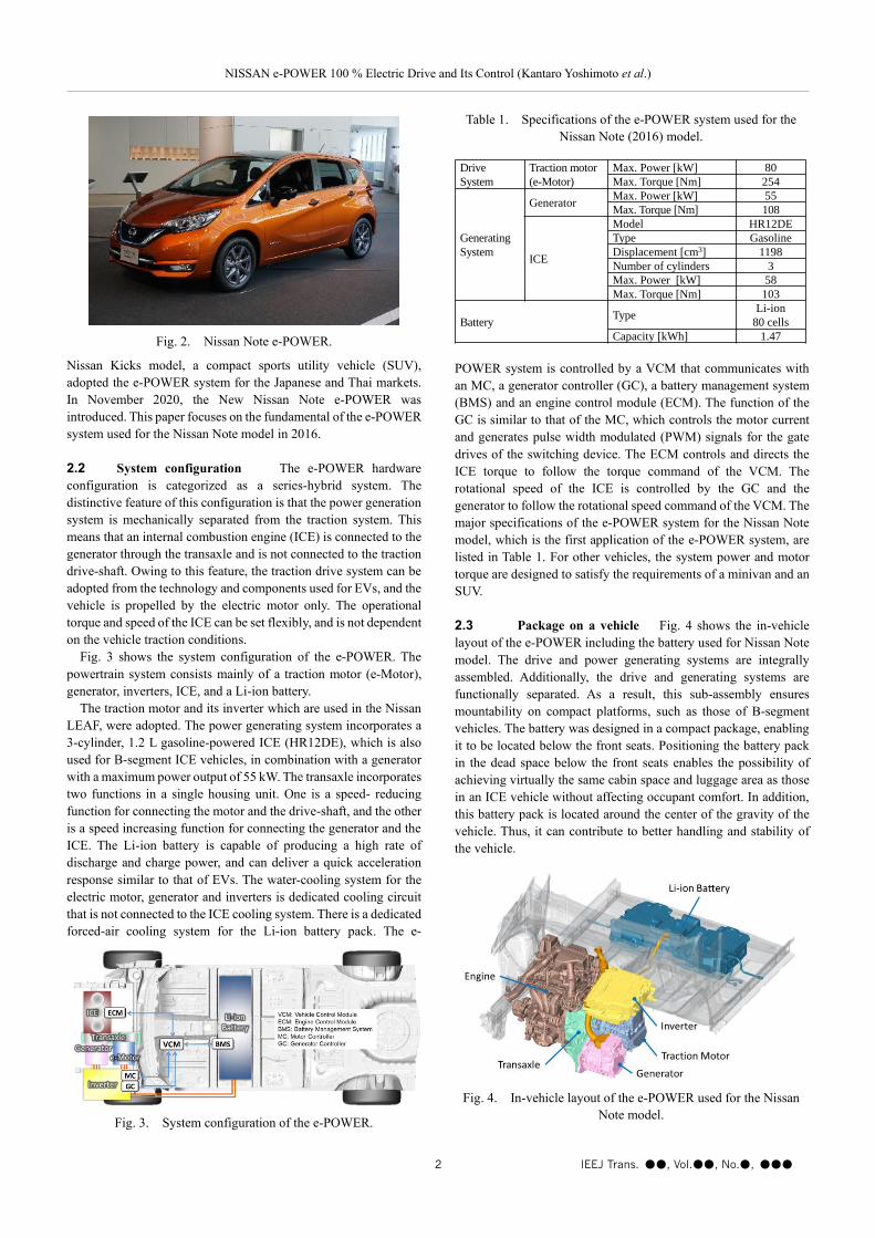
2.3 Package on a vehicle Fig. 4 shows the in-vehicle
layout of the e-POWER including the battery used for Nissan Note
model. The drive and power generating systems are integrally
assembled. Additionally, the drive and generating systems are
functionally separated. As a result, this sub-assembly ensures
mountability on compact platforms, such as those of B-segment
vehicles. The battery was designed in a compact package, enabling
it to be located below the front seats. Positioning the battery pack
in the dead space below the front seats enables the possibility of
achieving virtually the same cabin space and luggage area as those
in an ICE vehicle without affecting occupant comfort. In addition,
this battery pack is located around the center of the gravity of the
vehicle. Thus, it can contribute to better handling and stability of
the vehicle.
Fig. 2. Nissan Note e-POWER.
Fig. 3. System configuration of the e-POWER.
Fig. 4. In-vehicle layout of the e-POWER used for the Nissan
Note model.
Table 1. Specifications of the e-POWER system used for the
Nissan Note (2016) model.
Drive
System
Traction motor
(e-Motor)
Max. Power [kW] 80
Max. Torque [Nm] 254
Generating
System
GeneratorMax. Power [kW] 55
Max. Torque [Nm] 108
ICE
Model HR12DE
Type Gasoline
Displacement [cm3] 1198
Number of cylinders 3
Max. Power [kW] 58
Max. Torque [Nm] 103
BatteryType
Li-ion
80 cells
Capacity [kWh] 1.47
NISSAN e-POWER 100 % Electric Drive and Its Control (Kantaro Yoshimoto et al.)
3 IEEJ Trans. ●●, Vol.●●, No.●, ●●●
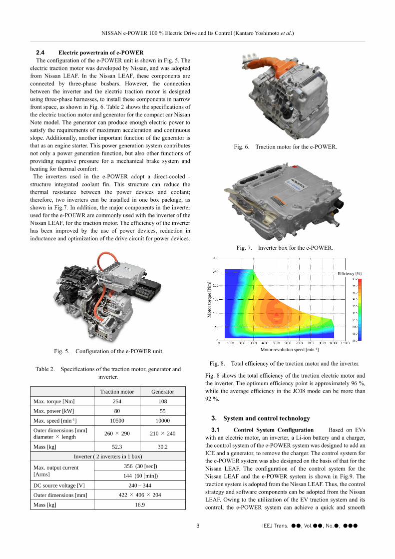
2.4 Electric powertrain of e-POWER
The configuration of the e-POWER unit is shown in Fig. 5. The
electric traction motor was developed by Nissan, and was adopted
from Nissan LEAF. In the Nissan LEAF, these components are
connected by three-phase busbars. However, the connection
between the inverter and the electric traction motor is designed
using three-phase harnesses, to install these components in narrow
front space, as shown in Fig. 6. Table 2 shows the specifications of
the electric traction motor and generator for the compact car Nissan
Note model. The generator can produce enough electric power to
satisfy the requirements of maximum acceleration and continuous
slope. Additionally, another important function of the generator is
that as an engine starter. This power generation system contributes
not only a power generation function, but also other functions of
providing negative pressure for a mechanical brake system and
heating for thermal comfort.
The inverters used in the e-POWER adopt a direct-cooled -
structure integrated coolant fin. This structure can reduce the
thermal resistance between the power devices and coolant;
therefore, two inverters can be installed in one box package, as
shown in Fig.7. In addition, the major components in the inverter
used for the e-POEWR are commonly used with the inverter of the
Nissan LEAF, for the traction motor. The efficiency of the inverter
has been improved by the use of power devices, reduction in
inductance and optimization of the drive circuit for power devices.
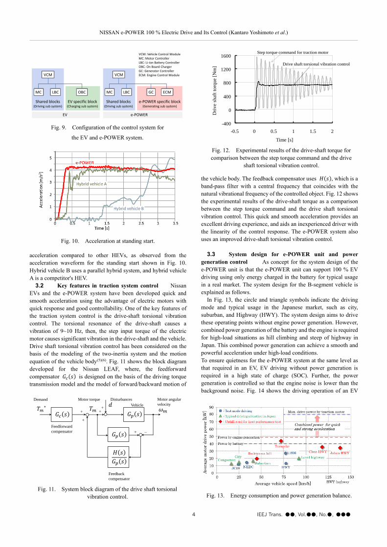
Fig. 8 shows the total efficiency of the traction electric motor and
the inverter. The optimum efficiency point is approximately 96 %,
while the average efficiency in the JC08 mode can be more than
92 %.
3. System and control technology
3.1 Control System Configuration Based on EVs
with an electric motor, an inverter, a Li-ion battery and a charger,
the control system of the e-POWER system was designed to add an
ICE and a generator, to remove the charger. The control system for
the e-POWER system was also designed on the basis of that for the
Nissan LEAF. The configuration of the control system for the
Nissan LEAF and the e-POWER system is shown in Fig.9. The
traction system is adopted from the Nissan LEAF. Thus, the control
strategy and software components can be adopted from the Nissan
LEAF. Owing to the utilization of the EV traction system and its
control, the e-POWER system can achieve a quick and smooth
Fig. 7. Inverter box for the e-POWER.
Fig. 8. Total efficiency of the traction motor and the inverter.
Motor revolution speed [min-1]
Mo
tor
torq
ue
[Nm
]
Efficiency [%]
Table 2. Specifications of the traction motor, generator and
inverter.
Traction motor Generator
Max. torque [Nm] 254 108
Max. power [kW] 80 55
Max. speed [min-1] 10500 10000
Outer dimensions [mm]
diameter × length260 × 290 210 × 240
Mass [kg] 52.3 30.2
Inverter ( 2 inverters in 1 box)
Max. output current
[Arms]
356 (30 [sec])
144 (60 [min])
DC source voltage [V] 240 – 344
Outer dimensions [mm] 422 × 406 × 204
Mass [kg] 16.9
Fig. 5. Configuration of the e-POWER unit.
Fig. 6. Traction motor for the e-POWER.
NISSAN e-POWER 100 % Electric Drive and Its Control (Kantaro Yoshimoto et al.)
4 IEEJ Trans. ●●, Vol.●●, No.●, ●●●
acceleration compared to other HEVs, as observed from the
acceleration waveform for the standing start shown in Fig. 10.
Hybrid vehicle B uses a parallel hybrid system, and hybrid vehicle
A is a competitor's HEV.
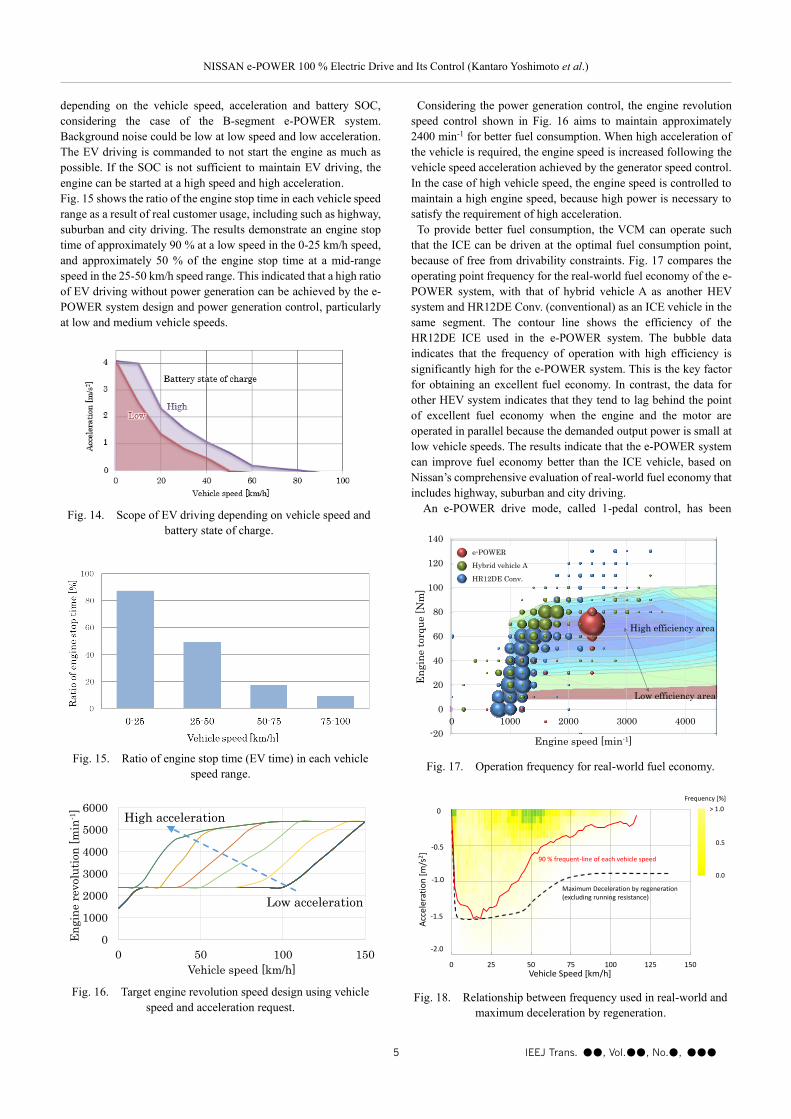
3.2 Key features in traction system control Nissan
EVs and the e-POWER system have been developed quick and
smooth acceleration using the advantage of electric motors with
quick response and good controllability. One of the key features of
the traction system control is the drive-shaft torsional vibration
control. The torsional resonance of the drive-shaft causes a
vibration of 9~10 Hz, then, the step input torque of the electric
motor causes significant vibration in the drive-shaft and the vehicle.
Drive shaft torsional vibration control has been considered on the
basis of the modeling of the two-inertia system and the motion
equation of the vehicle body(5)(6). Fig. 11 shows the block diagram
developed for the Nissan LEAF, where, the feedforward
compensator 𝐺𝑐(𝑠) is designed on the basis of the driving torque
transmission model and the model of forward/backward motion of
the vehicle body. The feedback compensator uses 𝐻(𝑠), which is a
band-pass filter with a central frequency that coincides with the
natural vibrational frequency of the controlled object. Fig. 12 shows
the experimental results of the drive-shaft torque as a comparison
between the step torque command and the drive shaft torsional
vibration control. This quick and smooth acceleration provides an
excellent driving experience, and aids an inexperienced driver with
the linearity of the control response. The e-POWER system also
uses an improved drive-shaft torsional vibration control.
3.3 System design for e-POWER unit and power
generation control As concept for the system design of the
e-POWER unit is that the e-POWER unit can support 100 % EV
driving using only energy charged in the battery for typical usage
in a real market. The system design for the B-segment vehicle is
explained as follows.
In Fig. 13, the circle and triangle symbols indicate the driving
mode and typical usage in the Japanese market, such as city,
suburban, and Highway (HWY). The system design aims to drive
these operating points without engine power generation. However,
combined power generation of the battery and the engine is required
for high-load situations as hill climbing and steep of highway in
Japan. This combined power generation can achieve a smooth and
powerful acceleration under high-load conditions.
To ensure quietness for the e-POWER system at the same level as
that required in an EV, EV driving without power generation is
required in a high state of charge (SOC). Further, the power
generation is controlled so that the engine noise is lower than the
background noise. Fig. 14 shows the driving operation of an EV
Fig. 12. Experimental results of the drive-shaft torque for
comparison between the step torque command and the drive
shaft torsional vibration control.
-400
0
400
800
1200
1600
-0.5 0 0.5 1 1.5 2
Dri
ve
shaf
t to
rqu
e [N
m]
-0.5 0 0.5 1 1.5 2
Time [s]
Drive shaft torsional vibration control
Step torque command for traction motor
Fig. 11. System block diagram of the drive shaft torsional
vibration control.
Feedforward
compensator
Demand
+
−
+
++
DisturbancesMotor torque
Vehicle
+
Motor angular
velocity
Feedback
compensator
Fig. 13. Energy consumption and power generation balance.
Fig. 9. Configuration of the control system for
the EV and e-POWER system.
VCM
OBCMC LBC ECMGCMC LBC
VCM
Shared blocks(Driving sub system)
EV specific block(Charging sub system)
e-POWER specific block(Generating sub system)
VCM: Vehicle Control ModuleMC: Motor ControllerLBC: Li-ion Battery ControllerOBC: On Board ChargerGC: Generator ControllerECM: Engine Control Module
Shared blocks(Driving sub system)
EV e-POWER
Fig. 10. Acceleration at standing start.
NISSAN e-POWER 100 % Electric Drive and Its Control (Kantaro Yoshimoto et al.)
5 IEEJ Trans. ●●, Vol.●●, No.●, ●●●
depending on the vehicle speed, acceleration and battery SOC,
considering the case of the B-segment e-POWER system.
Background noise could be low at low speed and low acceleration.
The EV driving is commanded to not start the engine as much as
possible. If the SOC is not sufficient to maintain EV driving, the
engine can be started at a high speed and high acceleration.
Fig. 15 shows the ratio of the engine stop time in each vehicle speed
range as a result of real customer usage, including such as highway,
suburban and city driving. The results demonstrate an engine stop
time of approximately 90 % at a low speed in the 0-25 km/h speed,
and approximately 50 % of the engine stop time at a mid-range
speed in the 25-50 km/h speed range. This indicated that a high ratio
of EV driving without power generation can be achieved by the e-
POWER system design and power generation control, particularly
at low and medium vehicle speeds.
Considering the power generation control, the engine revolution
speed control shown in Fig. 16 aims to maintain approximately
2400 min-1 for better fuel consumption. When high acceleration of
the vehicle is required, the engine speed is increased following the
vehicle speed acceleration achieved by the generator speed control.
In the case of high vehicle speed, the engine speed is controlled to
maintain a high engine speed, because high power is necessary to
satisfy the requirement of high acceleration.
To provide better fuel consumption, the VCM can operate such
that the ICE can be driven at the optimal fuel consumption point,
because of free from drivability constraints. Fig. 17 compares the
operating point frequency for the real-world fuel economy of the e-
POWER system, with that of hybrid vehicle A as another HEV
system and HR12DE Conv. (conventional) as an ICE vehicle in the
same segment. The contour line shows the efficiency of the
HR12DE ICE used in the e-POWER system. The bubble data
indicates that the frequency of operation with high efficiency is
significantly high for the e-POWER system. This is the key factor
for obtaining an excellent fuel economy. In contrast, the data for
other HEV system indicates that they tend to lag behind the point
of excellent fuel economy when the engine and the motor are
operated in parallel because the demanded output power is small at
low vehicle speeds. The results indicate that the e-POWER system
can improve fuel economy better than the ICE vehicle, based on
Nissan’s comprehensive evaluation of real-world fuel economy that
includes highway, suburban and city driving.
An e-POWER drive mode, called 1-pedal control, has been
Fig. 18. Relationship between frequency used in real-world and
maximum deceleration by regeneration.
0.00755 0 0 0 0 0 0 0 0 0 0 0 0 0 0 0 0 0 0 0 0 0 0 0 0 0 0 0 0 0 0 0 0 0 0 0 0 0 0 0 0 0 0 0 0 0 0 0 0 0 0 0 0 0 0 0 0 0 0 0 0 0 0 0 0 0 0 0 0 0 0 0 0 0 0 0
0 0 0 0 0 0 0 0 0 0 0 0 0 0 0 0 0 0 0 0 0 0 0 0 0 0 0 0 0 0 0 0 0 0 0 0 0 0 0 0 0 0 0 0 0 0 0 0 0 0 0 0 0 0 0 0 0 0 0 0 0 0 0 0 0 0 0 0 0 0 0 0 0 0 0 0
0 0 0 0 0 0 0 0 0 0 0 0 0 0 0 0 0 0 0 0 0 0 0 0 0 0 0 0 0 0 0 0 0 0 0 0 0 0 0 0 0 0 0 0 0 0 0 0 0 0 0 0 0 0 0 0 0 0 0 0 0 0 0 0 0 0 0 0 0 0 0 0 0 0 0 0
0 0 0 0 0 0 0 0 0 0 0 0 0 0 0 0 0 0 0 0 0 0 0 0 0 0 0 0 0 0 0 0 0 0 0 0 0 0 0 0 0 0 0 0 0 0 0 0 0 0 0 0 0 0 0 0 0 0 0 0 0 0 0 0 0 0 0 0 0 0 0 0 0 0 0 0
0 0 0 0 0 0 0 0 0 0 0 0 0 0 0 0 0 0 0 0 0 0 0 0 0 0 0 0 0 0 0 0 0 0 0 0 0 0 0 0 0 0 0 0 0 0 0 0 0 0 0 0 0 0 0 0 0 0 0 0 0 0 0 0 0 0 0 0 0 0 0 0 0 0 0 0
0 0 0 0 0 0 0 0 0 0 0 0 0 0 0 0 0 0 0 0 0 0 0 0 0 0 0 0 0 0 0 0 0 0 0 0 0 0 0 0 0 0 0 0 0 0 0 0 0 0 0 0 0 0 0 0 0 0 0 0 0 0 0 0 0 0 0 0 0 0 0 0 0 0 0 0
0 0 0 0 0 0 0 0 0 0 0 0 0 0 0 0 0 0 0 0 0 0 0 0 0 0 0 0 0 0 0 0 0 0 0 0 0 0 0 0 0 0 0 0 0 0 0 0 0 0 0 0 0 0 0 0 0 0 0 0 0 0 0 0 0 0 0 0 0 0 0 0 0 0 0 0
0 0 0 0 0 0 0 0 0 0 0 0 0 0 0 0 0 0 0 0 0 0 0 0 0 0 0 0 0 0 0 0 0 0 0 0 0 0 0 0 0 0 0 0 0 0 0 0 0 0 0 0 0 0 0 0 0 0 0 0 0 0 0 0 0 0 0 0 0 0 0 0 0 0 0 0
0 0 0 0 0 0 0 0 0 0 0 0 0 0 0 0 0 0 0 0 0 0 0 0 0 0 0 0 0 0 0 0 0 0 0 0 0 0 0 0 0 0 0 0 0 0 0 0 0 0 0 0 0 0 0 0 0 0 0 0 0 0 0 0 0 0 0 0 0 0 0 0 0 0 0 0
0 0 0 0 0 0 0 0 0 0 0 0 0 0 0 0 0 0 0 0 0 0 0 0 0 0 0 0 0 0 0 0 0 0 0 0 0 0 0 0 0 0 0 0 0 0 0 0 0 0 0 0 0 0 0 0 0 0 0 0 0 0 0 0 0 0 0 0 0 0 0 0 0 0 0 0
0 0 0 0 0 0 0 0 0 0 0 0 0 0 0 0 0 0 0 0 0 0 0 0 0 0 0 0 0 0 0 0 0 0 0 0 0 0 0 0 0 0 0 0 0 0 0 0 0 0 0 0 0 0 0 0 0 0 0 0 0 0 0 0 0 0 0 0 0 0 0 0 0 0 0 0
0 0 0 0 0 0 0 0 0 0 0 0 0 0 0 0 0 0 0 0 0 0 0 0 0 0 0 0 0 0 0 0 0 0 0 0 0 0 0 0 0 0 0 0 0 0 0 0 0 0 0 0 0 0 0 0 0 0 0 0 0 0 0 0 0 0 0 0 0 0 0 0 0 0 0 0
0 0 0 0 0 0 0 0 0 0 0 0 0 0 0 0 0 0 0 0 0 0 0 0 0 0 0 0 0 0 0 0 0 0 0 0 0 0 0 0 0 0 0 0 0 0 0 0 0 0 0 0 0 0 0 0 0 0 0 0 0 0 0 0 0 0 0 0 0 0 0 0 0 0 0 0
0 0 0 0 0 0 0 0 0 0 0 0 0 0 0 0 0 0 0 0 0 0 0 0 0 0 0 0 0 0 0 0 0 0 0 0 0 0 0 0 0 0 0 0 0 0 0 0 0 0 0 0 0 0 0 0 0 0 0 0 0 0 0 0 0 0 0 0 0 0 0 0 0 0 0 0
0 0 0 0 0 0 0 0 0 0 0 0 0 0 0 0 0 0 0 0 0 0 0 0 0 0 0 0 0 0 0 0 0 0 0 0 0 0 0 0 0 0 0 0 0 0 0 0 0 0 0 0 0 0 0 0 0 0 0 0 0 0 0 0 0 0 0 0 0 0 0 0 0 0 0 0
0 0 0 0 0 0 0 0 0 0 0 0 0 0 0 0 0 0 0 0 0 0 0 0 0 0 0 0 0 0 0 0 0 0 0 0 0 0 0 0 0 0 0 0 0 0 0 0 0 0 0 0 0 0 0 0 0 0 0 0 0 0 0 0 0 0 0 0 0 0 0 0 0 0 0 0
0 0 0 0 0 0 0 0 0 0 0 0 0 0 0 0 0 0 0 0 0 0 0 0 0 0 0 0 0 0 0 0 0 0 0 0 0 0 0 0 0 0 0 0 0 0 0 0 0 0 0 0 0 0 0 0 0 0 0 0 0 0 0 0 0 0 0 0 0 0 0 0 0 0 0 0
0 0 0 0 0 0 0 0 0 0 0 0 0 0 0 0 0 0 0 0 0 0 0 0 0 0 0 0 0 0 0 0 0 0 0 0 0 0 0 0 0 0 0 0 0 0 0 0 0 0 0 0 0 0 0 0 0 0 0 0 0 0 0 0 0 0 0 0 0 0 0 0 0 0 0 0
0 0 0 0 0 0 0 0 0 0 0 0 0 0 0 0 0 0 0 0 0 0 0 0 0 0 0 0 0 0 0 0 0 0 0 0 0 0 0 0 0 0 0 0 0 0 0 0 0 0 0 0 0 0 0 0 0 0 0 0 0 0 0 0 0 0 0 0 0 0 0 0 0 0 0 0
0 0 0 0 0 0 0 0 0 0 0 0 0 0 0 0 0 0 0 0 0 0 0 0 0 0 0 0 0 0 0 0 0 0 0 0 0 0 0 0 0 0 0 0 0 0 0 0 0 0 0 0 0 0 0 0 0 0 0 0 0 0 0 0 0 0 0 0 0 0 0 0 0 0 0 0
90 % frequent-line of each vehicle speed
Maximum Deceleration by regeneration(excluding running resistance)
0 25 50 75 100 125 150
> 1.0
0.0
0.5
Vehicle Speed [km/h]
Frequency [%]
-0.5
-1.0
-1.5
-2.0
Acc
ele
rati
on
[m
/s2]
0
Fig. 17. Operation frequency for real-world fuel economy.
-20
0
20
40
60
80
100
120
140
0 1000 2000 3000 4000
Engine speed [min-1]
En
gin
e t
orq
ue [
Nm
]
Hybrid vehicle A
e-POWER
HR12DE Conv.
High efficiency area
Low efficiency area
Fig. 14. Scope of EV driving depending on vehicle speed and
battery state of charge.
Fig. 16. Target engine revolution speed design using vehicle
speed and acceleration request.
0
1000
2000
3000
4000
5000
6000
0 50 100 150
En
gin
e r
evolu
tion
[m
in-1
]
Vehicle speed [km/h]
Low acceleration
High acceleration
Fig. 15. Ratio of engine stop time (EV time) in each vehicle
speed range.

NISSAN e-POWER 100 % Electric Drive and Its Control (Kantaro Yoshimoto et al.)
6 IEEJ Trans. ●●, Vol.●●, No.●, ●●●
developed for the e-POWER system as a technique for enabling
easy control of the vehicle speed using only the accelerator pedal.
This mode provides both good fuel economy and driving pleasure.
In addition, the e-POWER system is characterized by its ability to
regenerate power at extremely low vehicle speeds. This
characteristic is a good advantage of the e-POWER drive mode.
Fig. 18 shows that the solid line indicating 90 % of the necessary
deceleration for ordinary driving in the market can be covered by
the dotted line indicating the maximum deceleration by
regeneration of the e-POWER drive mode. Thus, the frequency of
switching from the accelerator pedal to the brake pedal can be
reduced by approximately 90 %, in typical usage. The e-POWER
drive mode also incorporates fine control procedures to enhance its
practical utility. As an example, the neutral position for accelerator
pedal operation is set at a point where it is unlikely to exhaust the
driver, and the distribution of the driving force is centered on this
position. Simultaneously, a dead zone is provided in the neutral
position as a control measure that easily sustains coasting to
improve the fuel economy. The control is also regulated to match
the driving situation, to enable smooth deceleration by operating the
accelerator pedal even when traveling uphill or downhill. On snowy
roads and other surfaces with a low coefficient of friction, the fine-
tuned control of the driving force can control the traction motor in
all speed ranges. As a result, the deceleration can be controlled to
close to the slip limit to enhance drivability.
4. Conclusion
Nissan has developed a 100 % electrified powertrain system
called e-POWER, which exhibits key features such as quick
response, smooth acceleration, smooth deceleration, and quietness.
The quick response and smooth acceleration can be achieved owing
to the 100 % electric motor drive, and control strategy that has been
adopted from the Nissan LEAF and improved further. The quietness
was designed and controlled using power generation control and
engine speed control. The e-POWER drive mode with 100 %
electric deceleration achieves smooth deceleration with linearity,
controllability and efficiency. Nissan announced that the e-POWER
will be launched in the global market in the near future. The 100 %
electric motor drive used by EVs and e-POWERs will lead the
vehicle electrification and solve social issues such as global
warming, in addition to providing driving pleasure and enriching
people's lives.
References
(1) S. Nakazawa, N. Nakada, "The Nissan LEAF electric powertrain", 32nd
International Vienna Motor Symposium, (2011)
(2) H. Shimizu, T. Okubo, I Hirano, S. Ishikawa, "Development of an integrated
electrified powertrain for a newly developed electric vehicle", SAE paper
2013-01-1759, (2013)
(3) A. Shibuya, N. Nakada, M. Kimura, "Development of a Brand New Hybrid
Powertrain for Compact Car Market", 25th Aachen Colloquium Automobile
and Engine Technology, (2016)
(4) Y.Konishi, M.Taira, H.Ootsuka, K.Yoshimoto, "Development of Electric
4WD System For Compact Hybrid Car", SAE Technical Paper 2019-01-2216,
(2019)
(5) T. Karikomi, K. Ito, T. Okubo, "Development of the Shaking Vibration
Control for Electric Vehicles", SICE-ICASE International Joint Conference,
(2006)
(6) H. Kawamura, K. Ito, T. Okubo, "Highly -Responsive Acceleration Control
for the Nissan LEAF Electric Vehicle", SAE World Congress & Exhibition,
(2011)
Kantaro Yoshimoto (Member) received the B.S., M.S., and Ph.D. from
Yokohama National University, Yokohama, Japan, in
1997, 1999, and 2010 respectively. In 2001, he joined
NISSAN Motor Co., Ltd. He performed research in
power electronics, and development of control system
for electric vehicles and hybrid electric vehicles. Since
2020, he is an Associate Professor with Tokyo Denki
University, Tokyo and his general interests include
power electronics, motor drive and electric vehicles.
Tomoyuki Hanyu (Non-member) received the B.S., M.S., from Keio
University, Yokohama, Japan, in 1996 and
1998respectively. Since 2001, he has worked for
NISSAN Motor Co., Ltd, and has directed
development of system and control for electric
vehicles and e-POWERs.