Embed Size (px)
Citation preview
1
ADVANCED ADAPTIVE PIR/MICROWAVE TECHNOLOGY
SENSOR
R
U.S. PATENT NO. 5,331,308
INSTALLATION INSTRUCTIONS
C-100STE 30' RANGE C-100STLRE 50' RANGE
WI862A 1/03
2
GENERAL DESCRIPTION ............................................................ 3 SPECIFICATIONS ...................................................................... 3 FEATURES ................................................................................ 3 ORDERING INFORMATION ....................................................... 4 BASIC OPERATION ................................................................... 4 PIR ZONE DIMENSIONS ........................................................... 5 DETECTION PATTERNS ........................................................... 5 STANDARD LENS ...................................................................... 6
INSTALLATION ............................................................................. 7 CHOOSING A SUITABLE LOCATION ........................................ 7
MOUNTING THE SENSOR ...................................................... 7 CHANGING THE LENS ............................................................ 7 WIRING .................................................................................... 8 ADJUSTING THE COVERAGE AREA ...................................... 9 TESTING THE COVERAGE AREA ........................................... 11 COMPLETING THE INSTALLATION ........................................ 13 OPTIONAL LENSES ................................................................. 14 ADVANCED FEATURES .......................................................... 15 TROUBLESHOOTING GUIDE .................................................. 15
MODEL C-100STLRE .................................................................. 16
TABLE OF CONTENTS
© NAPCO 1996. All Rights Reserved
Napco Security Systems, Inc., 333 Bayview Avenue, Amityville, New York 11701 Sales, Repairs & Technical Service (Toll Free): (800) 645-9445
Direct Line to Technical Service (Toll Free): (800) 645-9440
3
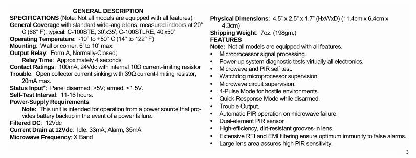
GENERAL DESCRIPTION SPECIFICATIONS (Note: Not all models are equipped with all features). General Coverage with standard wide-angle lens, measured indoors at 20°
C (68° F), typical: C-100STE, 30x35; C-100STLRE, 40x50 Operating Temperature: -10° to +50° C (14° to 122° F) Mounting: Wall or corner, 6 to 10 max. Output Relay: Form A, Normally-Closed; Relay Time: Approximately 4 seconds Contact Ratings: 100mA, 24Vdc with internal 10Ω current-limiting resistor Trouble: Open collector current sinking with 39Ω current-limiting resistor,
20mA max. Status Input*: Panel disarmed, >5V; armed, <1.5V. Self-Test Interval: 11-16 hours. Power-Supply Requirements: Note: This unit is intended for operation from a power source that pro-
vides battery backup in the event of a power failure. Filtered DC: 12Vdc Current Drain at 12Vdc: Idle, 33mA; Alarm, 35mA Microwave Frequency: X Band
Physical Dimensions: 4.5 x 2.5" x 1.7 (HxWxD) (11.4cm x 6.4cm x
4.3cm) Shipping Weight: 7oz. (198gm.) FEATURES Note: Not all models are equipped with all features. • Microprocessor signal processing. • Power-up system diagnostic tests virtually all electronics. • Microwave and PIR self test. • Watchdog microprocessor supervision. • Microwave circuit supervision. • 4-Pulse Mode for hostile environments. • Quick-Response Mode while disarmed. • Trouble Output. • Automatic PIR operation on microwave failure. • Dual-element PIR sensor • High-efficiency, dirt-resistant grooves-in lens. • Extensive RFI and EMI filtering ensure optimum immunity to false alarms. • Large lens area assures high PIR sensitivity.
4
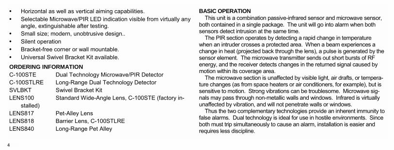
• Horizontal as well as vertical aiming capabilities. • Selectable Microwave/PIR LED indication visible from virtually any
angle, extinguishable after testing. • Small size; modern, unobtrusive design.. • Silent operation • Bracket-free corner or wall mountable. • Universal Swivel Bracket Kit available.
ORDERING INFORMATION C-100STE Dual Technology Microwave/PIR Detector C-100STLRE Long-Range Dual Technology Detector SVLBKT Swivel Bracket Kit LENS100 Standard Wide-Angle Lens, C-100STE (factory in-
stalled) LENS817 Pet-Alley Lens LENS818 Barrier Lens, C-100STLRE LENS840 Long-Range Pet Alley
BASIC OPERATION This unit is a combination passive-infrared sensor and microwave sensor,
both contained in a single package. The unit will go into alarm when both sensors detect intrusion at the same time.
The PIR section operates by detecting a rapid change in temperature when an intruder crosses a protected area. When a beam experiences a change in heat (projected back through the lens), a pulse is generated by the sensor element. The microwave transmitter sends out short bursts of RF energy, and the receiver detects changes in the returned signal caused by motion within its coverage area.
The microwave section is unaffected by visible light, air drafts, or tempera-ture changes (as from space heaters or air conditioners, for example), but is sensitive to motion. Strong vibrations can be troublesome. Microwave sig-nals may pass through non-metallic walls and windows. Infrared is virtually unaffected by vibration, and will not penetrate walls or windows.
Thus the two complementary technologies provide an inherent immunity to false alarms. Dual technology is ideal for use in hostile environments. Since both must trip simultaneously to cause an alarm, installation is easier and requires less discipline.
5
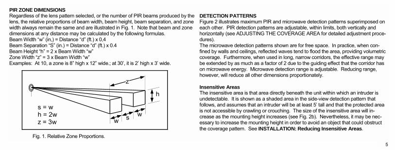
PIR ZONE DIMENSIONS Regardless of the lens pattern selected, or the number of PIR beams produced by the lens, the relative proportions of beam width, beam height, beam separation, and zone width always remain the same and are illustrated in Fig. 1. Note that beam and zone dimensions at any distance may be calculated by the following formulas. Beam Width w (in,) = Distance d (ft.) x 0,4 Beam Separation S (in.) = Distance d (ft.) x 0.4 Beam Height h = 2 x Beam Width w Zone Width z = 3 x Beam Width w Examples: At 10, a zone is 8 high x 12 wide.; at 30, it is 2 high x 3 wide. Fig. 1. Relative Zone Proportions.
DETECTION PATTERNS Figure 2 illustrates maximum PIR and microwave detection patterns superimposed on each other. PIR detection patterns are adjustable, within limits, both vertically and horizontally (see ADJUSTING THE COVERAGE AREA for detailed adjustment proce-dures). The microwave detection patterns shown are for free space. In practice, when con-fined by walls and ceilings, reflected waves tend to flood the area, providing volumetric coverage. Furthermore, when used in long, narrow corridors, the effective range may be extended by as much as a factor of 2 due to the guiding effect that the corridor has on microwave energy. Microwave detection range is adjustable. Reducing range, however, will reduce all other dimensions proportionately. Insensitive Areas The insensitive area is that area directly beneath the unit within which an intruder is undetectable. It is shown as a shaded area in the side-view detection pattern that follows, and assumes that an intruder will be at least 5 tall and that the protected area is not accessible by crawling or crouching. The size of the insensitive area will in-crease as the mounting height increases (see Fig. 2b). Nevertheless, it may be nec-essary to increase the mounting height in order to avoid an object that could obstruct the coverage pattern. See INSTALLATION: Reducing Insensitive Areas.
z
w s w
h
s = w h = 2w z = 3w
6
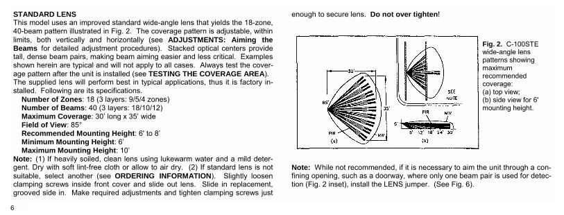
STANDARD LENS This model uses an improved standard wide-angle lens that yields the 18-zone, 40-beam pattern illustrated in Fig. 2. The coverage pattern is adjustable, within limits, both vertically and horizontally (see ADJUSTMENTS: Aiming the Beams for detailed adjustment procedures). Stacked optical centers provide tall, dense beam pairs, making beam aiming easier and less critical. Examples shown herein are typical and will not apply to all cases. Always test the cover-age pattern after the unit is installed (see TESTING THE COVERAGE AREA). The supplied lens will perform best in typical applications, thus it is factory in-stalled. Following are its specifications.
Number of Zones: 18 (3 layers: 9/5/4 zones) Number of Beams: 40 (3 layers: 18/10/12) Maximum Coverage: 30 long x 35 wide Field of View: 85° Recommended Mounting Height: 6' to 8 Minimum Mounting Height: 6 Maximum Mounting Height: 10
Note: (1) If heavily soiled, clean lens using lukewarm water and a mild deter-gent. Dry with soft lint-free cloth or allow to air dry. (2) If standard lens is not suitable, select another (see ORDERING INFORMATION). Slightly loosen clamping screws inside front cover and slide out lens. Slide in replacement, grooved side in. Make required adjustments and tighten clamping screws just
enough to secure lens. Do not over tighten!
Note: While not recommended, if it is necessary to aim the unit through a con-fining opening, such as a doorway, where only one beam pair is used for detec-tion (Fig. 2 inset), install the LENS jumper. (See Fig. 6).
Fig. 2. C-100STE wide-angle lens patterns showing maximum recommended coverage: (a) top view; (b) side view for 6' mounting height.
7
INSTALLATION CHOOSING A SUITABLE LOCATION
The unit may be either wall mounted or corner mounted. Corner mounting is gen-erally recommended as greater coverage may be obtained. Select a rigid surface that is relatively free of vibration.
Position the sensor with respect to access doors or windows so that an intruder will pass across its field of view, not directly toward or away from it. Avoid areas con-taining devices that may pose a chronic problem to either sensor. For the dual-technology feature to be truly effective in rendering the unit free from false alarms, neither sensor should detect intrusion under normal conditions. Note: The unit is shipped from the factory with Jumper J1 in the Alarm position.
In selecting mounting height, aiming, and range, also consider the following: (a) the size and shape of the area to be protected. In a large or irregularly-shaped area, the use of two or more units may be advisable for volumetric coverage; (b) the PIR lens installed (see ORDERING INFORMATION for available optional lenses); (c) objects that may block detection; (d) animals in the protected area; and (e) an in-truders likely path, usually determined by the location of a door or window. MOUNTING THE SENSOR
Open the case by inserting a small screwdriver in the slot at the bottom and push-ing up slightly. Remove the front cover.
An array of push-thru holes is provided in the rear case to simplify wall or corner mounting. (If corner mounting, do not use the hole at the lower-left corner, near the terminal strip). A round push-thru hole permits cable entry at the bottom (see Fig. 4). Cutaway notches in the rear ease will accommodate surface-mounted cables if the outer jacket is removed. Note: Any unused knockout must be sealed with the caulking material supplied to eliminate drafts and prevent entry by insects. CHANGING THE LENS
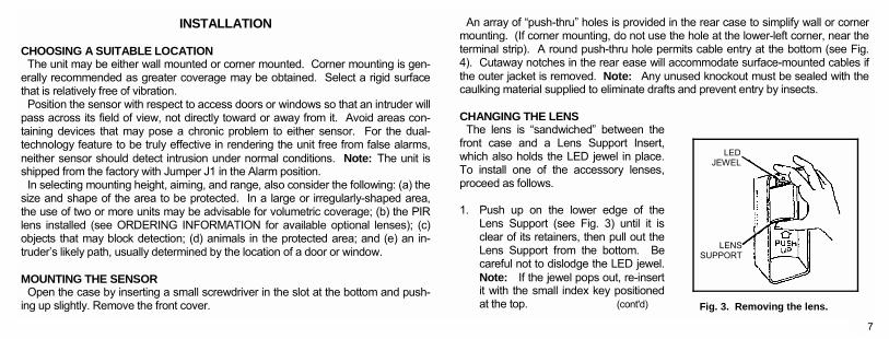
The lens is sandwiched between the front case and a Lens Support Insert, which also holds the LED jewel in place. To install one of the accessory lenses, proceed as follows.
1. Push up on the lower edge of the
Lens Support (see Fig. 3) until it is clear of its retainers, then pull out the Lens Support from the bottom. Be careful not to dislodge the LED jewel. Note: If the jewel pops out, re-insert it with the small index key positioned at the top. (cont'd)
LED JEWEL
LENS SUPPORT
Fig. 3. Removing the lens.
8
2. Slide out the lens and install the replacement correctly oriented. 3. Replace the Lens Support: Slip the Lens Support under the top lens guides
with its two tabs straddling the LED jewel, then push in at the bottom until the Lens Support snaps into place.
WIRING
Remove the wire entry hole (see MOUNTING THE SENSOR) to gain access to the terminal strip. (Be sure to caulk around the wires where they exit the case; see previous Note). Route wires to the terminal strip as shown in Fig. 4 and connect as follows:
Power (Terminals 1 [+] & 2 [-]). Apply 12Vdc to Terminals 1 [+] and 2 [-]. The power source may be regulated or unregulated. Power should be supplied from a control panel or other power source equipped with a rechargeable bat-tery backup to maintain operation in the event of a power failure. Refer to SPECIFICATIONS for power-supply requirements.
Alarm Relay (Form A) Contacts (Terminals 3 & 4). These contacts are rated at 100mA, 24Vdc and are normally closed. When the sensor is operat-ing, either detection of an intruder or loss of power will cause the relay contacts to open.
Alarm Relay (Form C) Contacts (Terminals 3,4 & 5). These contacts are
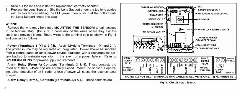
CORNER MOUNT HOLE JUMPER BLOCK
INDEX NOTCH
HEIGHT SCALE
HEIGHT LOCK SCREW, C-100STLRE
MICROWAVE CAVITY
MICROWAVE RANGE CONTROL CORNER MOUNT HOLE LED
PIR SENSOR
HEIGHT LOCK SCREW, C-100STE
TAMPER TERMINALS (TAMPER OPTIONAL)
WALL MOUNT HOLE CORNER MOUNT HOLE
PINOUT,FORM-A RELAY
*WHERE EQUIPPED
ALAR
M
TROU
BLE*
STAT
US* NC
1 2 3 5 6 4
POW
ER + −
POW
ER + −
1 2 3 5 6 4
TROU
BLE*
ALAR
M
NC C NO
PINOUT,FORM-C RELAY
*WHERE EQUIPPED TO 24HR
ZONE
NC*
TAMPER (OPTIONAL) 7 8
*WHEN SET
NOTE: (1) NOT ALL TERMINALS AVAILABLE IN ALL VERSIONS. (2) NC WHEN SET.
Fig. 4. Circuit board layout.
9
rated at 100mA, 24Vdc. Terminal 4 is common. Terminal 3 is normally closed; Terminal 5 is normally open. When the sensor is operating, either detection of an intruder or loss of power will cause the relay to trip.
Status and Trouble (Where equipped) Wiring to Terminals 5 (Status) and 6 (Trouble) are only required if using the spe-cial features of this unit. Refer to ADVANCED FEATURES.
Status Input (Terminal 5). Connect to the Status terminal (Arm Lug) of the con-trol panel. A low at Terminal 5 tells the sensor that the panel is armed.
Trouble (Terminal 6). This is an open-collector output that produces an active low to signal a trouble condition.
ADJUSTING THE COVERAGE AREA Self Test The self-test diagnostic simulates motion and tests the PIR sensor, amplifier and related PIR circuitry, the microwave transmitter, receiver, and associated micro-wave circuitry. This test is initiated each time the unit is powered up and ran-domly at 11- to 16-hour intervals after the last alarm to ensure that the unit is al-ways in operating order. At power-up, the LED will turn on and both the alarm and trouble outputs will be held safe. If the unit is operating properly, the LED will extinguish after about 1 minute. However, if it fails the self test, the LED will flash rapidly, indicating a need for service. After the LED goes out, indicating a
successful self-test, proceed as follows: Setting the Height Scale The Height Scale must be set to obtain the maximum recommended coverage. Remove the front cover. Note that the Height scale is printed along the edge of the circuit board in the upper-left corner (see Fig. 4). The scale calibrations rep-resent sensor mounting height (6 to 10 feet) for the standard wide-angle lens only. To set, loosen the Lock Screw shown in the illustration to slide the board up or down, and align the index embossed into the rear case with the pointer on the scale representing the mounting height of the unit. Then tighten the Lock Screw (do not over-tighten!).
Reducing Insensitive Areas The insensitive area is a function of mounting height and Height-Scale setting. When used in a room or area that requires less range than the recommended maximum, the insensitive area may be substantially reduced by raising the circuit board, as previously described, to a Height-Scale setting higher than the actual sensor mounting height.
Lateral Beam Adjustment PIR beams may be shifted up to 6° in either direction (± ½ zone for the Stan-dard Wide-Angle lens). The left edge of the top lens guide acts as the
10
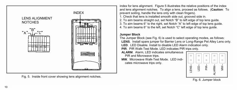
index for lens alignment. Figure 5 illustrates the relative positions of the index and lens alignment notches. To align a lens, proceed as follows. (Caution: To prevent soiling, handle the lens only with clean fingers). 1. Check that lens is installed smooth side out, grooved side in. 2. To aim beams straight out, set Notch B to left edge of top lens guide. 3. To aim beams 6° to the right, set Notch A to left edge of top lens guide. 4. To aim beams 6° to the left, set Notch C left edge of top lens guide. Jumper Block The Jumper Block (see Fig. 6) is used to select operating modes, as follows:
LENS. Install spare jumper for Barrier Lens or Long-Range Pet Alley Lens only. LED. LED Disable. Install to disable LED Alarm indication only. PIR. PIR Walk-Test Mode. LED indicates PIR trips only. ALARM. Alarm, LED indicates simultaneous
PIR and Microwave trips. MW. Microwave Walk-Test Mode. LED indi-
cates microwave trips only.
LENS ALIGNMENT NOTCHES
INDEX
Fig. 5. Inside front cover showing lens alignment notches.
LEN
S--
LED
--
PIR
--
ALAR
M--
MW
--
Fig. 6. Jumper block
11
The alarm relay will operate only with the LED jumper installed or the ALARM jumper installed. Therefore, after testing, be sure to replace the jumper in the ALARM position for normal LED operation, or in the LED position, which pre-vents the LED from lighting on an alarm condition.
Four-Pulse Mode. This is the least-sensitive mode, recommended for hostile environments or areas with pets, where an intruder must cross several beam pairs to trip an alarm. To lock the unit into the 4-Pulse Mode while maintaining adaptive microwave operation, install both the PIR jumper and the MW jumper. Microwave Range Adjustment
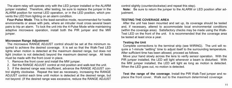
The microwave RANGE ADJUST control should be set at the minimum re-quired to achieve the desired coverage. It is set so that the Walk-Test LED lights when motion is detected at the maximum desired range, but does not light (motion is not detected) beyond the maximum desired range. All tests must be made with the front cover in place.
1. Remove the front cover and install the MW jumper. 2. Set the RANGE ADJUST control at mid position and walk-test the unit. 3. If the desired range was insufficient, advance the RANGE ADJUST con-
trol slightly clockwise. Repeat the test as necessary, increasing the RANGE ADJUST control each time until motion is detected at the desired range, but not beyond. (If the desired range was excessive, reduce the RANGE ADJUST
control slightly (counterclockwise) and repeat this step). Note: Be sure to return the jumper to the ALARM or LED position after ad-
justment.
TESTING THE COVERAGE AREA After the unit has been mounted and set up, its coverage should be tested
and, if necessary, altered to accommodate local environmental conditions (within the coverage area). Satisfactory checks may be made using the Walk-Test LED on the front of the unit. It is recommended that the coverage area be tested at least once a year.
Testing the Unit Complete connections to the terminal strip (see WIRING). The unit will re-
quire a 1-minute settling time to adjust itself to the surrounding temperature. After sufficient time has been allowed, proceed as follows.
Move your hand slowly across the lens to verify sensor operation. With the PIR jumper installed, the LED will light whenever a beam is disturbed. With the MW jumper installed, the LED will light as long as motion is detected. When the LED goes out, no motion is detected.
Test the range of the coverage. Install the PIR Walk-Test jumper and re-
place the front cover. Walk out to the maximum determined coverage
12
distance, then walk across the field of coverage. The LED will remain lit as long as motion is detected. Repeat this test with the microwave MW Walk-Test jumper installed. Repeat once again with the ALARM, jumper in-stalled. Confirm that the LED lights at the maximum desired range, but not beyond.
Test the width of the coverage. Install the PIR Walk-Test jumper (Fig. 6) and replace the front cover. Walk across the coverage area and confirm LED response. Repeat with the MW Walk-Test jumper installed, and once again with the ALARM jumper installed.
Test for environmental disturbances. Note: The following test is applicable to the PIR section only. There are no
provisions for testing the microwave section for environmental disturbances. This test will determine if detection occurs with no human activity in the protec-tion area. Be sure to make this test with all potential disruptive devices (heaters, air conditioners, etc.) in full operation. Note that blowing curtains may be troublesome.
Install the PIR Walk-Test jumper. Leave the protection area. If an alarm condition occurs with no one in the coverage area, temporarily block the entire lens with a sheet of cardboard or other opaque material. If the alarm condition persists with the lens covered, it is not caused by an environmental distur-bance, and the system requires attention. (Check for low supply voltage from
the control center, or for an intermittent connection.) Remove the cardboard (or other material) from the front of the lens. If the
alarm condition reoccurs, turn oft heaters, air conditioners, etc. one by one and note the effects. If the offending device must remain in operation within the coverage area, try to reposition the device and/or alter the aim of the sen-sor slightly to effect a suitable compromise. Bear in mine, however, that each time the coverage pattern is altered, the foregoing environmental test must be repeated.
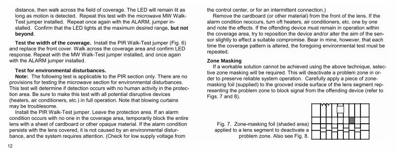
Zone Masking If a workable solution cannot be achieved using the above technique, selec-
tive zone masking will be required. This will deactivate a problem zone in or-der to preserve reliable system operation. Carefully apply a piece of zone-masking foil (supplied) to the grooved inside surface of the lens segment rep-resenting the problem zone to block signal from the offending device (refer to Figs. 7 and 8).
Fig. 7. Zone-masking foil (shaded area) applied to a lens segment to deactivate a
problem zone. Also see Fig. 8.
13
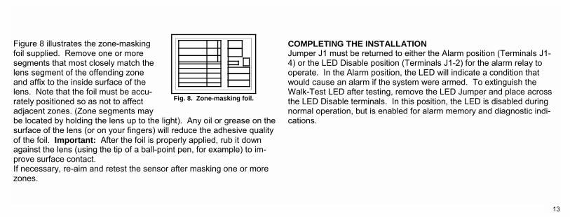
Figure 8 illustrates the zone-masking foil supplied. Remove one or more segments that most closely match the lens segment of the offending zone and affix to the inside surface of the lens. Note that the foil must be accu-rately positioned so as not to affect adjacent zones. (Zone segments may be located by holding the lens up to the light). Any oil or grease on the surface of the lens (or on your fingers) will reduce the adhesive quality of the foil. Important: After the foil is properly applied, rub it down against the lens (using the tip of a ball-point pen, for example) to im-prove surface contact. If necessary, re-aim and retest the sensor after masking one or more zones.
COMPLETING THE INSTALLATION Jumper J1 must be returned to either the Alarm position (Terminals J1-4) or the LED Disable position (Terminals J1-2) for the alarm relay to operate. In the Alarm position, the LED will indicate a condition that would cause an alarm if the system were armed. To extinguish the Walk-Test LED after testing, remove the LED Jumper and place across the LED Disable terminals. In this position, the LED is disabled during normal operation, but is enabled for alarm memory and diagnostic indi-cations.
Fig. 8. Zone-masking foil.
14
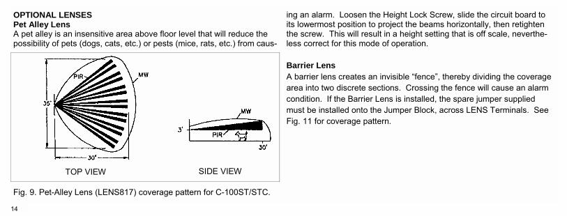
OPTIONAL LENSES Pet Alley Lens A pet alley is an insensitive area above floor level that will reduce the possibility of pets (dogs, cats, etc.) or pests (mice, rats, etc.) from caus-
ing an alarm. Loosen the Height Lock Screw, slide the circuit board to its lowermost position to project the beams horizontally, then retighten the screw. This will result in a height setting that is off scale, neverthe-less correct for this mode of operation. Barrier Lens A barrier lens creates an invisible fence, thereby dividing the coverage area into two discrete sections. Crossing the fence will cause an alarm condition. If the Barrier Lens is installed, the spare jumper supplied must be installed onto the Jumper Block, across LENS Terminals. See Fig. 11 for coverage pattern.
TOP VIEW SIDE VIEW
Fig. 9. Pet-Alley Lens (LENS817) coverage pattern for C-100ST/STC.
15
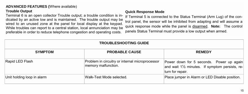
ADVANCED FEATURES (Where available) Trouble Output Terminal 6 is an open collector Trouble output; a trouble condition is in-dicated by an active low and is maintained. The trouble output may be wired to an unused zone at the panel for local display at the keypad. While troubles can report to a central station, local annunciation may be preferable in order to reduce telephone congestion and operating costs.
Quick Response Mode If Terminal 5 is connected to the Status Terminal (Arm Lug) of the con-trol panel, the sensor will be inhibited from adapting and will assume a quick response mode while the panel is disarmed. Note: The control panels Status Terminal must provide a low output when armed.
SYMPTOM PROBABLE CAUSE REMEDY
Rapid LED Flash Problem in circuitry or internal microprocessor memory malfunction.
Power down for 5 seconds. Power up again and wait 1½ minutes. If symptom persists, re-turn for repair.
Unit holding loop in alarm Walk-Test Mode selected. Place jumper in Alarm or LED Disable position.
TROUBLESHOOTING GUIDE
½
16
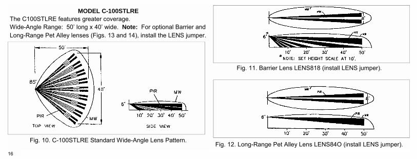
MODEL C-100STLRE The C100STLRE features greater coverage. Wide-Angle Range: 50 long x 40 wide. Note: For optional Barrier and Long-Range Pet Alley lenses (Figs. 13 and 14), install the LENS jumper.
Fig. 10. C-100STLRE Standard Wide-Angle Lens Pattern. Fig. 12. Long-Range Pet Alley Lens LENS84O (install LENS jumper).
Fig. 11. Barrier Lens LENS818 (install LENS jumper).

17
NOTES

18
NOTES
19
NAPCO SECURITY SYSTEMS, INC. (NAPCO) warrants its products to be free from manufacturing defects in materials and workmanship for thirty-six months following the date of manufacture. NAPCO will, within said period, at its option, repair or replace any product failing to operate correctly without charge to the original purchaser or user. This warranty shall not apply to any equipment, or any part thereof, which has been repaired by others, improperly installed, improperly used, abused, altered, damaged, subjected to acts of God, or on which any serial numbers have been altered, defaced or removed. Seller will not be responsible for any dismantling or reinstallation charges. THERE ARE NO WARRANTIES, EXPRESS OR IMPLIED, WHICH EXTEND BEYOND THE DESCRIPTION ON THE FACE HEREOF. THERE IS NO EX-PRESS OR IMPLIED WARRANTY OF MERCHANTABILITY OR A WARRANTY OF FITNESS FOR A PARTICULAR PURPOSE. ADDITIONALLY, THIS WAR-RANTY IS IN LIEU OF ALL OTHER OBLIGATIONS OR LIABILITIES ON THE PART OF NAPCO. Any action for breach of warranty, including but not limited to any implied war-ranty of merchantability, must be brought within the six months following the end of the warranty period. IN NO CASE SHALL NAPCO BE LIABLE TO ANYONE FOR ANY CONSEQUENTIAL OR INCIDENTAL DAMAGES FOR BREACH OF
THIS OR ANY OTHER WARRANTY, EXPRESS OR IMPLIED, EVEN IF THE LOSS OR DAMAGE IS CAUSED BY THE SELLERS OWN NEGLIGENCE OR FAULT. In case of defect, contact the security professional who installed and maintains your security system. In order to exercise the warranty, the product must be returned by the security professional, shipping costs prepaid and insured to NAPCO. After repair or replacement, NAPCO assumes the cost of returning products under warranty. NAPCO shall have no obligation under this warranty, or otherwise, if the product has been repaired by others, improperly installed, improperly used, abused, altered, damaged, subjected to accident, nuisance, flood, fire or acts of God, or on which any serial numbers have been altered, defaced or removed. NAPCO will not be responsible for any dismantling, reas-sembly or reinstallation charges. This warranty contains the entire warranty. It Is the sole warranty and any prior agreements or representations, whether oral or written, are either merged herein or are expressly cancelled. NAPCO neither assumes, nor authorizes any other person purporting to act on its behalf to modify, to change, or to assume for it, any other warranty or liability concerning its products. (cont'd)
NAPCO LIMITED WARRANTY
20
In no event shall NAPCO be liable for an amount in excess of NAPCO's original selling price of the product, for any loss or damage, whether direct, indirect, incidental, consequential, or otherwise arising out of any failure of the product. Sellers warranty, as hereinabove set forth, shall not be enlarged, diminished or affected by and no obligation or liability shall arise or grow out of Sellers ren-dering of technical advice or service in connection with Buyers order of the goods furnished hereunder. NAPCO RECOMMENDS THAT THE ENTIRE SYSTEM BE COMPLETELY TESTED WEEKLY. Warning: Despite frequent testing, and due to, but not limited to, any or all of the following; criminal tampering, electrical or communications disruption, it is possible for the system to fail to perform as expected. NAPCO does not repre-sent that the product/system may not be compromised or circumvented; or that the product or system will prevent any personal injury or property loss by bur-glary, robbery, fire or otherwise; nor that the product or system will in all cases provide adequate warning or protection. A properly installed and maintained alarm may only reduce risk of burglary, robbery, fire or otherwise but it is not insurance or a guarantee that these events will not occur. CONSEQUENTLY, SELLER SHALL HAVE NO LIABILITY FOR ANY PERSONAL INJURY, PROP-ERTY DAMAGE, OR OTHER LOSS BASED ON A CLAIM THE PRODUCT
FAILED TO GIVE WARNING. Therefore, the installer should in turn advise the consumer to take any and all precautions for his or her safety including, but not limited to, fleeing the premises and calling police or fire department, in order to mitigate the possibilities of harm and/or damage. NAPCO is not an insurer of either the property or safety of the users family or employees, and limits its liability for any loss or damage including incidental or consequential damages to NAPCOs original selling price of the product regard-less of the cause of such loss or damage. Some states do not allow limitations on how long an implied warranty lasts or do not allow the exclusion or limitation of incidental or consequential damages, or differentiate in their treatment of limitations of liability for ordinary or gross negligence, so the above limitations or exclusions may not apply to you. This Warranty gives you specific legal rights and you may also have other rights which vary from state to state.