Embed Size (px)
Citation preview
Advanced Architectures and Control Concepts for More µGrids
Contract No: SES6-019864
WORK PACKAGE E
DE2: Report on Interface Equipment Requirements for LV DG devices
Final Version
June 2008

Document Information
Deliverable: DE2
Title: Report on interface equipment requirements for LV DG devices
Date: 2008-06-30
Workpackage(s): WPE: Standardization of technical and commercial protocols and hardware
Task(s): TE3 – Interface Equipment Requirements
Coordination: J. Oyarzabal1 [email protected]
Authors: F. Psomadellis2 [email protected]
J. Oyarzabal1 [email protected]
N. Hatziargyriou3
A. Dimeas3
C. Schwaegerl4
A. Sensing4
J.M. Yarza5 [email protected]
1LABEIN, 2ANCO, 3NTUA, 4Siemens, 5ZIV
Access: Project Consortium
European Commission
X PUBLIC
Status: _____ For Information
_____ Draft Version
_____ Final Version (Internal document)
____ Submission for Approval (deliverable)
__X__ Final Version (deliverable, approved on)

MoreMicroGrids STREP project funded by the EC under 6FP, SES6-019864
WPE: DE2 Interface Equipment Requirements for LV DG Devices 3
Contents
1. Introduction..................................................................................................... 7
2. MV & LV Equipment and Software Tools...................................................... 8
2.1. Requirements overview................................................................................ 8
2.2. MV equipment ............................................................................................ 11
2.3. Low voltage equipment .............................................................................. 22
2.4. Monitoring, protection and control equipment ............................................ 25
2.5. Telecommunication equipment................................................................... 27
2.6. Software applications and miscellaneous................................................... 33
3. Computer Aided Design Software Tools .................................................... 39
3.1. Requirements overview.............................................................................. 39
3.2. Engineering Software ................................................................................. 40
4. References .................................................................................................... 53
5. Web Sites....................................................................................................... 54
6. Glossary ........................................................................................................ 55
7. Annexes......................................................................................................... 57
7.1. Annex A: Network integration of a 5 MW solar park ................................... 57
7.2. Annex B: Operational and control requirements of load controllers ........... 60
7.3. Annex C: Electrical Designer description ................................................... 65

MoreMicroGrids STREP project funded by the EC under 6FP, SES6-019864
WPE: DE2 Interface Equipment Requirements for LV DG Devices 4
List of Figures
Figure 2-1: Vacuum circuit breaker ........................................................................................12
Figure 2-2: Vacuum circuit-breaker/dis-connector unit...........................................................12
Figure 2-3: Vacuum interrupter ..............................................................................................12
Figure 2-4: Switch disconnector .............................................................................................13
Figure 2-5: HV HRC fuses with fuse base link .......................................................................14
Figure 2-6: Block-type current transformer.............................................................................15
Figure 2-7: Surge arrester ......................................................................................................16
Figure 2-8: Numerical protection relays .................................................................................17
Figure 2-9: Overview of protection grading schemes.............................................................18
Figure 2-10: Relay functions ..................................................................................................19
Figure 2-11: Three-phase stacked current limiting reactor (Trench) ......................................20
Figure 2-12: Example SIPLINK – a MV DC Coupler in Distribution systems for coupling of
galvanic separated parts of the network with active power flow control .................................21
Figure 2-13: LV air circuit breaker ..........................................................................................22
Figure 2-14: LV compact circuit breaker ................................................................................22
Figure 2-15: LV fuse switch disconnector ..............................................................................23
Figure 2-16: Requirement classes of LV arresters.................................................................24
Figure 2-17: Power meter.......................................................................................................25
Figure 2-18: Ethernet Switch (19” Rack) ...............................................................................28
Figure 2-19: Ethernet Switch (DIN) ........................................................................................28
Figure 2-20: GPS NTP synchroniser......................................................................................29
Figure 2-21: Wireless network router .....................................................................................31
Figure 2-22: Serial to Ethernet / Wireless bridge / gateway ...................................................32

MoreMicroGrids STREP project funded by the EC under 6FP, SES6-019864
WPE: DE2 Interface Equipment Requirements for LV DG Devices 5
Figure 2-23: System structure for the communication in the energy distribution (Siemens) ..33
Figure 2-24: Power management modules ............................................................................34
Figure 2-25: Tasks of system planning ..................................................................................35
Figure 2-26: Planning of power system protection .................................................................36
Figure 3-1: AmiKIT: Floor plant of HV metal clad cubicles.....................................................41
Figure 3-2: VisualSCL single-line substation schematic ........................................................43
Figure 3-3: Internal data model needs ...................................................................................45
Figure 3-4: Import module need .............................................................................................46
Figure 3-5: Some targets for the installation electrical engineering .......................................47
Figure 3-6: IED configuration edition......................................................................................48
Figure 3-7: IED configuration maintenance............................................................................49
Figure 3-8: Library editor ........................................................................................................49
Figure 3-9: Catalogue editor...................................................................................................50
Figure 3-10: Documentation modules ....................................................................................51
Figure 7-1: Solarpark Leipziger Land .....................................................................................57
Figure 7-2: PV plant conception .............................................................................................58
Figure 7-3: Symmetry control and THD improvement at the connection point to the grid......59
Figure 7-4: ILC Integrated web server....................................................................................61
Figure 7-5: Typical installation of an ILC Unit.........................................................................62
MoreMicroGrids STREP project funded by the EC under 6FP, SES6-019864
WPE: DE2 Interface Equipment Requirements for LV DG Devices 6
List of Tables
Table 2-I: Excerpt of ANSI/EEE relay codes ..........................................................................17

MoreMicroGrids STREP project funded by the EC under 6FP, SES6-019864
WPE: DE2 Interface Equipment Requirements for LV DG Devices 7
1. Introduction
This report is aimed to review interface equipment requirements applicable to Low Voltage
(LV) distributed generation technologies. This document is structured into two main different
parts covering a brief summary of applicable products from Siemens’ catalogue and the
integration of IEC 61850 standard into electric enginery tools respectively. Finally, some
annexes contribute with complementary information and examples.
A short review of MV and LV equipment and software tools is aimed to provide an example
of the availability of commercial products suitable for µGrid construction and deployment
from the electrical point of view. Those aspects resulting from the specific grid code
requirements, the applicable legal normative and the internal organization and arrangements
among parties contributing with µGrid equipment are out of the scope of the report.
The extension of the IEC 61850 standard out of the original substation environment into
providing the basic framework supporting from DER modelling (IEC 61850-7-420) to other
generation sources (IEC 61400-25 for wind farms or 61850-7-410 for hydro power) requires
an update on other engineering applications and tools. This fact is exemplified considering
the case of CAD tools used for electrical engineering, so far, derived from drawing tools
where some “intelligence” is added to manage three phase electric systems.
Annex A describes a large PV installation in Germany; the interesting output of the case is
related to the use of Siemens’s SIMATIC/SIPROTEC control system –off the self product– to
integrate advanced functionalities into the PV plant such as custom reactive power or
harmonic current controls.
Annex B provides some insights on the local load controllers developed for the Kythnos
island test site in Gaidouromantra. Some of the studies developed in the project have shown
the importance of proper load controls to face sudden or specific events at µGrids; for
instance, the stability after the transition from the grid connected mode into islanded mode
may be compromised depending on the generation-consumption balance requiring some
load shedding scheme for security reasons. This chapter describes some functionalities
incorporated to the load controllers and aimed for this specific test case purposes.
MoreMicroGrids STREP project funded by the EC under 6FP, SES6-019864
WPE: DE2 Interface Equipment Requirements for LV DG Devices 8
2. MV & LV Equipment and Software Tools
This chapter focuses on the different equipment used in the network: switches for
disconnection, protection, meter, converters, etc.; It also considers computer aided tools for
engineering that integrate advanced functionalities such as protection configuration in
traditional graphical design applications.
Siemens Power Transmission and Distribution Group (PTD) is a recognised product supplier,
systems integrator and service provider for all tasks and activities involving transmission and
distribution of electrical energy. It offers intelligent solutions for the transmission and
distribution of power from generating plants to customers.
Siemens’ service includes the setting up of complete turnkey installations, offers advice,
planning, operation and training and provides expertise and commitment as the complexity of
this task requires. Backed by the experience of worldwide projects, Siemens can always offer
its customers the optimum cost-effective concept individually tailored to their needs.
In this chapter an overview about interface equipment for medium voltage (MV) and low
voltage (LV) networks based on Siemens catalogue is provided; their specific requirements
(where applicable) for use in µGrids and Multi-µGrids systems are introduced.
µSysCom is a communications equipment manufacturer. The company is a division of ZIV
group, whom is considered a leading manufacturer of components and systems in protection,
control and measurement equipment for electrical substations
Within ZIV group, µSysCom is focused on increasing the communications functionality of
existing products. Additionally, it also addresses new markets on industrial applications that
are different form the electric utility sector.
The commercial catalogue of µSysCom is the base for the section devoted to discuss some
telecommunication alternatives and needs.
2.1. Requirements overview
This section provides an overview of technologies and interface equipment that should be
considered in detail concerning µGrids. While LV equipment is required to connect different
individual µGrid components such as generation units, responsible loads and intelligent

MoreMicroGrids STREP project funded by the EC under 6FP, SES6-019864
WPE: DE2 Interface Equipment Requirements for LV DG Devices 9
devices; in contrast, MV equipment is required considering the Multi-µGrids aspect where it
is assumed that different LV µGrids structures are combined and controlled as an intelligent
MV feeder by means of the CAMC.
2.1.1. Distribution on MV level
- MV equipment1
• Circuit breakers
• Switches, disconnectors, grounding switches
• MV HRC fuses, switch/fuse combinations
• Current and voltage transformers
• Protection relays
• Substation control and automation
• Special devices for neutral earthing (e.g. earthing resistors, earthing transformers)
• Surge arresters
- Other MV equipment
• Special transformer (e.g. for neutral grounding)
• Reactors
• Capacitor banks
- MV Power quality
• Flexible AC transmission systems (FACTS)
• Power factor correction units
• Harmonic filters
Typically, there are not any specific requirements for MV switchgear and transformers used
for distributed generation (DG) installations or µGrids although some concrete functional
characteristic may recommend slightly different attributes. For instance, if a µGrid is able of
1 Main equipment such as transformers, lines, etc. are not listed.
MoreMicroGrids STREP project funded by the EC under 6FP, SES6-019864
WPE: DE2 Interface Equipment Requirements for LV DG Devices 10
keeping the energy supply to the associated customers when the main MV is out of service,
the switchgear would need a synchronization relay for the transition from the isolated
operation back to the default interconnected mode.
2.1.2. Distribution on LV level
- Circuit breaker devices and fuse systems
• Circuit breakers (air circuit breakers, compact circuit breakers)
• LV HRC fuses
• Fuse switch disconnectors
• Lightning current and surge arresters
- Converters
• AC/DC converters
• AC/AC converters
- LV Power quality
• Filter modules for harmonic suppression
• Power factor correction units
2.1.3. Monitoring, protection, and control equipment, special devices
- Monitoring and protection relays
- Disconnecting protection
- Voltage controllers (LV)
- Soft starters for motors
2.1.4. Meters and measuring instruments
- Meters
- Measuring instruments
- Transducers
- Test terminals

MoreMicroGrids STREP project funded by the EC under 6FP, SES6-019864
WPE: DE2 Interface Equipment Requirements for LV DG Devices 11
2.1.5. Power management systems
- Visualization systems
- Event and status signal recording
- Measuring and optimizing the energy flow
- Systematic maintenance planning
2.1.6. Engineering software
- Network planning and dimensioning tools
- Support tools for selective protection settings
Again, no specific requirements exist for LV switchgear and distribution boards with respect
to DG applications.
A more detailed description of selected interface equipment and its requirements with
respect to µGrids is done in the following sections.
2.2. MV equipment
2.2.1. MV Circuit breakers
Medium-voltage circuit breakers (Figure 2-1 and Figure 2-2) serve as incoming and outgoing
circuit breakers for power distribution in medium-voltage switchgear. They are used as circuit
breakers and load interrupters in networks, motors, generators, capacitors and transformers.

MoreMicroGrids STREP project funded by the EC under 6FP, SES6-019864
WPE: DE2 Interface Equipment Requirements for LV DG Devices 12
Figure 2-1: Vacuum circuit breaker2
Figure 2-2: Vacuum circuit-breaker/dis-
connector unit3
Mostly maintenance free vacuum interrupters are used for this providing a high reliability (Figure 2-3).
Figure 2-3: Vacuum interrupter
In combination with secondary relays, MV circuit breakers can provide definite and inverse
time-overcurrent protection, time-overcurrent protection with additional directional function or
differential protection. In larger distribution networks distance protection is also used.
2 Siemens 3AH 3 Siemens 3AH/3DC
MoreMicroGrids STREP project funded by the EC under 6FP, SES6-019864
WPE: DE2 Interface Equipment Requirements for LV DG Devices 13
MV circuit breakers shall comply with national and international standards such as IEC
60056, partially IEC 62271-100, IEC 60694, and BS 5311.
2.2.1.1. Protective characteristics
Secondary relays, whose characteristic curves are also determined by the current
transformation ratio, are normally used as protective devices in medium-voltage systems.
Static numerical protection devices are increasingly preferred.
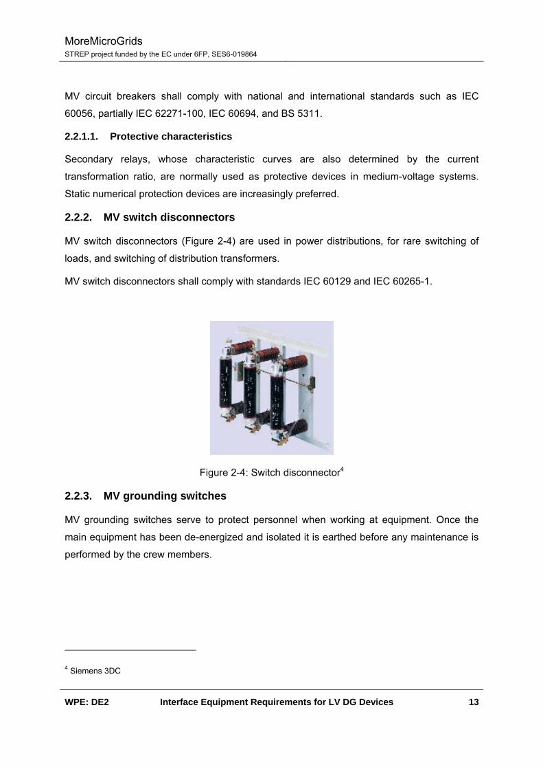
2.2.2. MV switch disconnectors
MV switch disconnectors (Figure 2-4) are used in power distributions, for rare switching of
loads, and switching of distribution transformers.
MV switch disconnectors shall comply with standards IEC 60129 and IEC 60265-1.
Figure 2-4: Switch disconnector4
2.2.3. MV grounding switches
MV grounding switches serve to protect personnel when working at equipment. Once the
main equipment has been de-energized and isolated it is earthed before any maintenance is
performed by the crew members.
4 Siemens 3DC

MoreMicroGrids STREP project funded by the EC under 6FP, SES6-019864
WPE: DE2 Interface Equipment Requirements for LV DG Devices 14
2.2.4. MV HRC fuses
High voltage high-breaking-capacity (HV5 HRC) fuses (Figure 2-5) can only be used for
short-circuit protection. They do not provide any overload protection. A minimum short-circuit
current is therefore required for correct operation. HV HRC fuses restrict the peak short-
circuit current and clear the fault initially. The protective characteristic is determined by the
selected rated current.
HV HRC fuses, mostly combined with switch disconnectors, are used for the protection of
small to medium-size distribution transformers, motors, capacitors, voltage transformers, and
small cable feeders.
HV HRC fuses shall comply with standard IEC 60282.
Figure 2-5: HV HRC fuses with fuse base link6
5 HV is used in the commercial and technical name for distinction from low voltage fuses. 6 Siemens 3GD/3GH

MoreMicroGrids STREP project funded by the EC under 6FP, SES6-019864
WPE: DE2 Interface Equipment Requirements for LV DG Devices 15
2.2.5. Instrument transformers
Current and voltage transformers –CT & VT respectively– serve for measurement of
electrical quantities in electrical installations (Figure 2-6). They provide transformation of
currents or voltages into quantities that are better suited for protective devices. In addition
they internally isolate high and low voltage parts from each other.
Current and voltage transformers shall comply with national and international standards IEC
60044-1, 60044-2, BS 7625, 7626, ANSI C57.13.
Figure 2-6: Block-type current transformer7
7 Siemens 4MA

MoreMicroGrids STREP project funded by the EC under 6FP, SES6-019864
WPE: DE2 Interface Equipment Requirements for LV DG Devices 16
2.2.6. Surge arresters
Surge arresters (Figure 2-7) protect the insulators of plants or plant sections against
excessive voltage stress up to 42 kV (typically). Overvoltage limiters are used to protect high-
voltage motors, dry-type transformers and cable networks up to 15 kV.
Figure 2-7: Surge arrester8
8 Siemens 3EE2
MoreMicroGrids STREP project funded by the EC under 6FP, SES6-019864
WPE: DE2 Interface Equipment Requirements for LV DG Devices 17
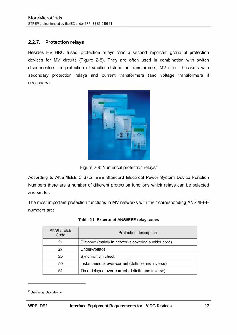
2.2.7. Protection relays
Besides HV HRC fuses, protection relays form a second important group of protection
devices for MV circuits (Figure 2-8). They are often used in combination with switch
disconnectors for protection of smaller distribution transformers, MV circuit breakers with
secondary protection relays and current transformers (and voltage transformers if
necessary).
Figure 2-8: Numerical protection relays9
According to ANSI/IEEE C 37.2 IEEE Standard Electrical Power System Device Function
Numbers there are a number of different protection functions which relays can be selected
and set for.
The most important protection functions in MV networks with their corresponding ANSI/IEEE
numbers are:
Table 2-I: Excerpt of ANSI/EEE relay codes
ANSI / IEEE Code Protection description
21 Distance (mainly in networks covering a wider area)
27 Under-voltage
25 Synchronism check
50 Instantaneous over-current (definite and inverse)
51 Time delayed over-current (definite and inverse)
9 Siemens Siprotec 4
MoreMicroGrids STREP project funded by the EC under 6FP, SES6-019864
WPE: DE2 Interface Equipment Requirements for LV DG Devices 18
ANSI / IEEE Code Protection description
67 Directional over-current (definite and inverse)
87 Differential (current)
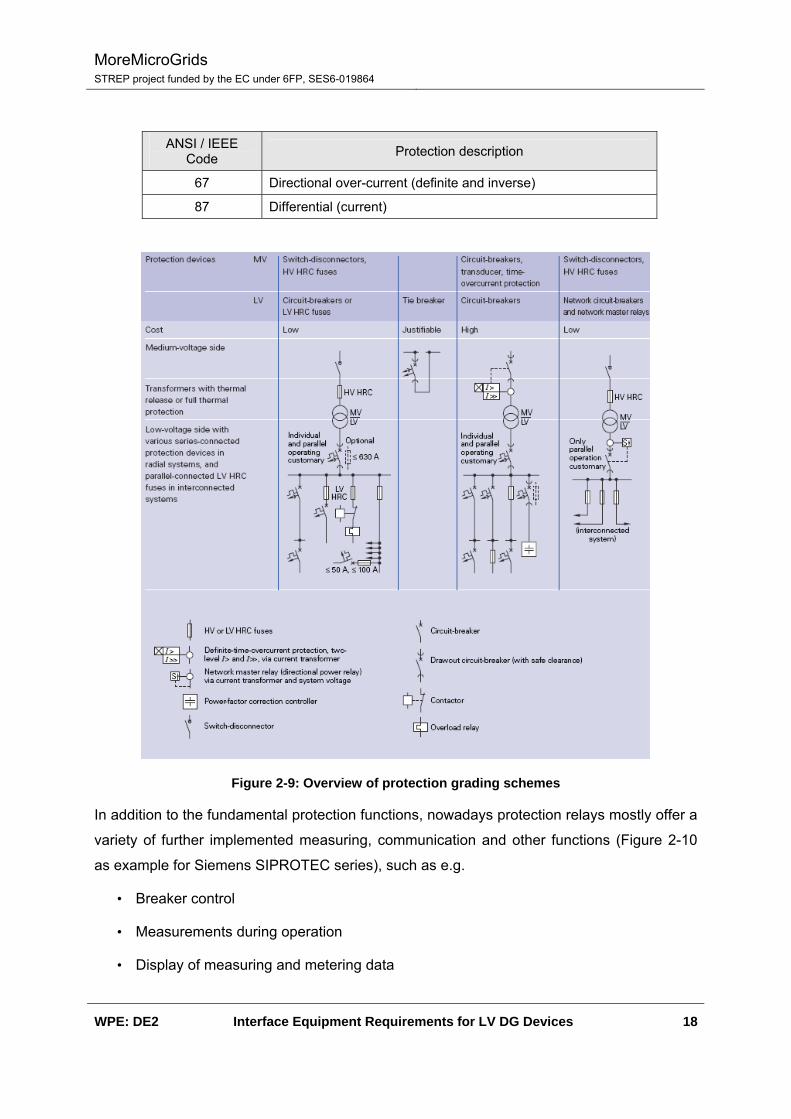
Figure 2-9: Overview of protection grading schemes
In addition to the fundamental protection functions, nowadays protection relays mostly offer a
variety of further implemented measuring, communication and other functions (Figure 2-10
as example for Siemens SIPROTEC series), such as e.g.
• Breaker control
• Measurements during operation
• Display of measuring and metering data

MoreMicroGrids STREP project funded by the EC under 6FP, SES6-019864
WPE: DE2 Interface Equipment Requirements for LV DG Devices 19
• Fault recorder
• Communication via copper or LWL lines with standard protocols (e.g.
RS232/485/LWL, IEC 61850, ICE 60870-5-103, PROFIBUS FMS/DP, DNP3.0,
MODBUS RTU)
• CFC (continuous flow chart) logic for implementation of interlocks etc.
Figure 2-10: Relay functions10
10 Siemens Siprotec 4
MoreMicroGrids STREP project funded by the EC under 6FP, SES6-019864
WPE: DE2 Interface Equipment Requirements for LV DG Devices 20
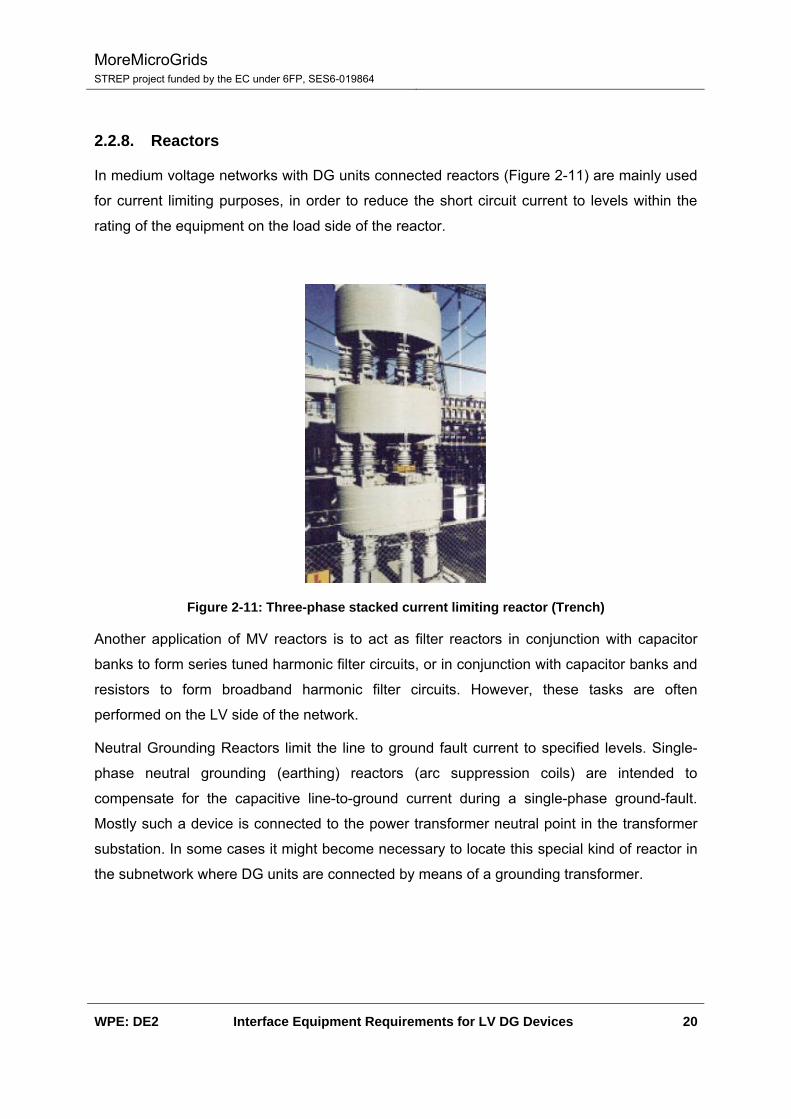
2.2.8. Reactors
In medium voltage networks with DG units connected reactors (Figure 2-11) are mainly used
for current limiting purposes, in order to reduce the short circuit current to levels within the
rating of the equipment on the load side of the reactor.
Figure 2-11: Three-phase stacked current limiting reactor (Trench)
Another application of MV reactors is to act as filter reactors in conjunction with capacitor
banks to form series tuned harmonic filter circuits, or in conjunction with capacitor banks and
resistors to form broadband harmonic filter circuits. However, these tasks are often
performed on the LV side of the network.
Neutral Grounding Reactors limit the line to ground fault current to specified levels. Single-
phase neutral grounding (earthing) reactors (arc suppression coils) are intended to
compensate for the capacitive line-to-ground current during a single-phase ground-fault.
Mostly such a device is connected to the power transformer neutral point in the transformer
substation. In some cases it might become necessary to locate this special kind of reactor in
the subnetwork where DG units are connected by means of a grounding transformer.

MoreMicroGrids STREP project funded by the EC under 6FP, SES6-019864
WPE: DE2 Interface Equipment Requirements for LV DG Devices 21
2.2.9. Neutral earthing resistors
The neutral earthing resistor is used in power distribution stations for neutral earthing of
generator and transformer windings, usually of the neutral point. Concerning µGrids
networks, they will be mostly applied in the transformer substation.
2.2.10. MV power quality equipment
MV Flexible AC transmission systems (FACTS), power factor correction units, and harmonic
filters are further devices that might in some cases be necessary or useful in MV distribution
networks (Figure 2-12). However, they are not regarded as essential equipment in µGrids
networks; therefore they are not dealt with in detail in the frame of this report. Intelligence
that may be necessary for active distribution networks can be integrated in power converters
of DG units.
Figure 2-12: Example SIPLINK – a MV DC Coupler in Distribution systems for coupling of galvanic separated parts of the network with active power flow control

MoreMicroGrids STREP project funded by the EC under 6FP, SES6-019864
WPE: DE2 Interface Equipment Requirements for LV DG Devices 22
2.3. Low voltage equipment
2.3.1. LV Circuit breakers
LV Circuit-breakers (Figure 2-13, Figure 2-14) serve as incoming and outgoing circuit
breakers for power distribution in low-voltage switchgear. They are responsible (together with
their built-in primary tripping devices) for overload and short-circuit protection in systems,
motors, generators and transformers.
Figure 2-13: LV air circuit breaker11
Figure 2-14: LV compact circuit breaker12
A large variety of additional features is available at up-to-date LV circuit breakers which
supports their application in networks with distributed generation. Among those are
particularly:
• a selection of high-sophisticated trip units offering many possibilities for setting the
breaker according to the requirements of the plant
• communication modules enabling the circuit breaker to interact with higher level power
management systems (see below)
11 Siemens Sentron 3WL 12 Siemens Sentron 3VL

MoreMicroGrids STREP project funded by the EC under 6FP, SES6-019864
WPE: DE2 Interface Equipment Requirements for LV DG Devices 23
2.3.2. Fuses / fuse switch disconnectors
Low voltage fuses (Figure 2-15) provide secure protection for electric systems, cables and
lines as well as for electric devices. A range of standardized types exists, starting from small
types (D0 system, e.g. NEOZED®) over medium-sized types (D system, e.g. DIAZED®)
towards large types (LV HRC), and special types for solid-state consumers (e.g. SITOR®).
Figure 2-15: LV fuse switch disconnector13
Fuse switch-disconnectors are able to make, conduct and break the specified rated current
(including a certain degree of overload). If a short circuit occurs, the fuse switch-disconnector
must be able to conduct a specified short-circuit current during a predefined time. The
switch-disconnector is opened (OFF) and closed (ON) by operating the handle unit. In the
”open position”, it meets the requirements for an isolating function.
Overload and short-circuit protection of downstream system components and devices is
provided by the LV HRC fuses integrated in the handle unit.
2.3.3. Lightning current / overvoltage protection devices
Surge protective devices (SPD) can be distinguished into lightning current and overvoltage
protection devices. They protect sensitive equipment against damages produced by
overvoltages. According to their causes, overvoltages are filed in two categories:
• LEMP (lightning electromagnetic impulse) – overvoltages that are caused by
atmospheric impact (e.g. direct lightning strike, electromagnetic lightning fields)
13 Siemens 3NP4
MoreMicroGrids STREP project funded by the EC under 6FP, SES6-019864
WPE: DE2 Interface Equipment Requirements for LV DG Devices 24
• SEMP (switching electromagnetic impulse) – overvoltages that are caused by
switching operations (e.g. breaking short circuits, operational switching of loads).
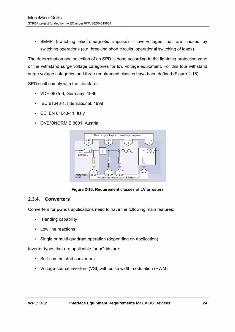
The determination and selection of an SPD is done according to the lightning protection zone
or the withstand surge voltage categories for low voltage equipment. For this four withstand
surge voltage categories and three requirement classes have been defined (Figure 2-16).
SPD shall comply with the standards:
• VDE 0675-6, Germany, 1996
• IEC 61643-1, International, 1998
• CEI EN 61643-11, Italy
• ÖVE/ÖNORM E 8001, Austria
Figure 2-16: Requirement classes of LV arresters
2.3.4. Converters
Converters for µGrids applications need to have the following main features:
• Islanding capability
• Low line reactions
• Single or multi-quadrant operation (depending on application)
Inverter types that are applicable for µGrids are:
• Self-commutated converters
• Voltage-source inverters (VSI) with pulse width modulation (PWM)
MoreMicroGrids STREP project funded by the EC under 6FP, SES6-019864
WPE: DE2 Interface Equipment Requirements for LV DG Devices 25
Line-commutated converters are of minor interest for µGrids applications due to their missing
islanding capability.
2.4. Monitoring, protection and control equipment
2.4.1. Meters and measuring instruments
Measuring instruments are used for measuring the consumption of electricity, gas, heat and
water for purposes of billing. In this regard, modern energy meters should be able to handle
differing regional tariff structures as well as complex tariffs in industrial applications.
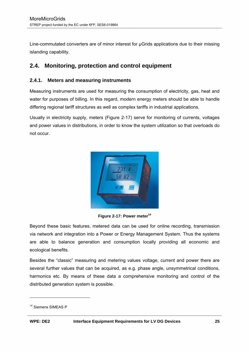
Usually in electricity supply, meters (Figure 2-17) serve for monitoring of currents, voltages
and power values in distributions, in order to know the system utilization so that overloads do
not occur.
Figure 2-17: Power meter14
Beyond these basic features, metered data can be used for online recording, transmission
via network and integration into a Power or Energy Management System. Thus the systems
are able to balance generation and consumption locally providing all economic and
ecological benefits.
Besides the “classic” measuring and metering values voltage, current and power there are
several further values that can be acquired, as e.g. phase angle, unsymmetrical conditions,
harmonics etc. By means of these data a comprehensive monitoring and control of the
distributed generation system is possible.
14 Siemens SIMEAS P
MoreMicroGrids STREP project funded by the EC under 6FP, SES6-019864
WPE: DE2 Interface Equipment Requirements for LV DG Devices 26
2.4.2. Special devices
Besides general monitoring and protection relays, DG units in public electricity networks shall
have a coupler circuit breaker with disconnecting element at the connection point to the grid.
This shall provide a disconnection from the public grid in case of non-permissible voltage and
frequency values in order to ensure that:
• The operating staff is well protected during maintenance work on the network.
• Unintentional in-feed into a subnetwork being separated from the public grid is not
possible.
• Supply into the public grid after a fault or at an auto-reclosure situation is prevented to
avoid damages at the generating equipment at return of voltage.
In order to provide these preconditions, the monitoring and protection features shall include
as a minimum:
• Under-voltage/over-voltage relay U<, U>
• Under-frequency/over-frequency relay f<, f>
• Vector (or load) jump relay
In addition to this, the tie circuit breaker shall be capable for synchronization.
At generating units supplying directly into the public grid a synchronizing device shall be
foreseen in order to ensure that the synchronizing conditions are fulfilled. It shall contain a
double frequency, a double voltage, and a zero-sequence measuring device. An automatic
synchronizing device is recommendable.
In networks with DG such as PV or wind energy plants, the system voltage between the
worst case operation points
• Low load / full generation highest voltage
• High load / no generation lowest voltage
can differ considerably. This can possibly require additional measures at the distribution
transformers, as e.g. automatic voltage controller, in order to keep the voltage in the
permissible margins.

MoreMicroGrids STREP project funded by the EC under 6FP, SES6-019864
WPE: DE2 Interface Equipment Requirements for LV DG Devices 27
2.5. Telecommunication equipment
Telecommunication equipment can be seen as an important µGrid enabler. When talking
about telecommunications, two different functions are required inside a LV grid:
• Networking infrastructure for automation: Following the market trends, an Ethernet
LAN seems to be the LV network automation basis. It should also be noted that similar
features to those found in IEC 61850 substations are required for µGrid networking
infrastructure. Synchronization must also be taken into account as power network
events must be tagged very precisely.
• Secure Remote Access: µGrids are not intended for islanded operation only but should
also be connected to the mains. In order to do so, appropriate telecom equipment
need to be deployed. In those cases, where the Utility has not their own telecom
infrastructure (fiber optics / private radio), the latter may rely on existing mobile
network carriers telecom infrastructure. For such telecom transport media appropriate
security mechanisms are needed.
2.5.1. Networking infrastructure for automation
µSysCom (ZIV group) provides the networking infrastructure that allows an Ethernet LAN
deployment inside µGrids. The commercial catalogue also introduces GPS based equipment
to synchronize all integrated IED’s.
2.5.1.1. SWT: Gigabit Ethernet / Fast Ethernet switches
During last years, the International Electrotechnical Commission (IEC), has created an
standard that strives for interoperability between the different electronical devices in charge
of automation within electrical substations: IEC-61850. This standard promotes the use of
Ethernet technology in local area communication networks.
µSysCom has developed the SWT family of Ethernet switches for such application. SWT
Ethernet Switches have been designed to fully accomplish the most hazardous performance
requirements for implementing Ethernet networks in electrical facilities.

MoreMicroGrids STREP project funded by the EC under 6FP, SES6-019864
WPE: DE2 Interface Equipment Requirements for LV DG Devices 28
Figure 2-18: Ethernet Switch (19” Rack) 15
Figure 2-19: Ethernet Switch (DIN) 16
µSysCom SWT managed switches include the following features:
• Full duplex – wired speed
• Automatic configuration of IP address
• NTP/SNTP Client
• VLAN support according to 802.1Q (also Q in Q)
• Broadcast Storm Control, configurable by the user for ingress and egress traffic
• Spanning Tree Protocol STP and RSTP according to 802.1D
• QoS (Quality of Service). 3 priority queues for each port are supported
• Port monitoring
• Management via CLI, TELNET, SNMP (RMON MIB)
• Remote Monitoring (RMON RFC 2819). 4 groups of monitoring elements available:
Statistics, History, Alarms and Events
• User friendly web page; easily configurable
• Configuration changes applicable at runtime
15 µSysCom 3SWT 16 µSysCom 3SWT
MoreMicroGrids STREP project funded by the EC under 6FP, SES6-019864
WPE: DE2 Interface Equipment Requirements for LV DG Devices 29
2.5.1.2. GPS: Time clock synchronizer
The distributed nature of electronic equipment in power systems adds complexity when
analyzing system wide events. Precise time accuracy, distributed throughout the network, is
critical for system synchronization and provides useful sequence of events enabling proper
analysis.
In this context, NTP (Network Time Protocol) is one of the most used protocols for
synchronizing the clocks of computer systems over packet-switched, variable-latency data
networks, getting 1 ms precision times inside an Ethernet LAN.
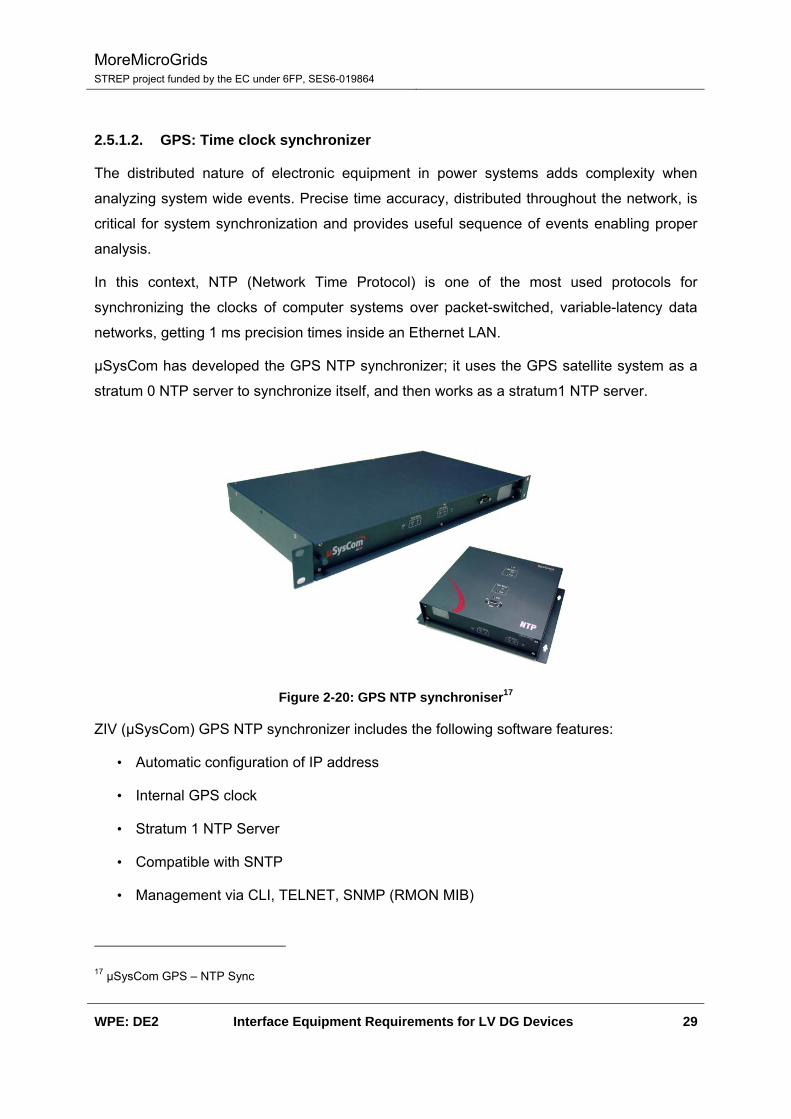
µSysCom has developed the GPS NTP synchronizer; it uses the GPS satellite system as a
stratum 0 NTP server to synchronize itself, and then works as a stratum1 NTP server.
Figure 2-20: GPS NTP synchroniser17
ZIV (µSysCom) GPS NTP synchronizer includes the following software features:
• Automatic configuration of IP address
• Internal GPS clock
• Stratum 1 NTP Server
• Compatible with SNTP
• Management via CLI, TELNET, SNMP (RMON MIB)
17 µSysCom GPS – NTP Sync

MoreMicroGrids STREP project funded by the EC under 6FP, SES6-019864
WPE: DE2 Interface Equipment Requirements for LV DG Devices 30
• Remote Monitoring (RMON RFC 2819). 4 groups of monitoring elements available:
Statistics, History, Alarms and Events
• User friendly web page, easily configurable
• Configuration changes applied at runtime
• Firmware upgradeable
2.5.2. Secure Remote access
In this section two different options are introduced.
• EMR wireless routers: Having deployed an Ethernet LAN, the most straightforward
option is to use a router to provide remote accessibility to the network components
measurements and control actions. Nevertheless, security requirements are to be
taken into account, so features such as IPSec are highly recommended when
integrating elements into the Utility IT infrastructure through 3rd party network carriers.
• SIP product family: SIP is a very powerful product family as it will allow both, an
Ethernet LAN and an asynchronous serial device to share the same wireless
connection.
2.5.2.1. EMR: Wireless cellular routers
In last decades we have faced an important increase in the mobile communications market.
Current estimates indicate that there are, at least, 1.500 millions of mobile communications
subscribers in the world.
Cellular mobile communications systems are able to provide telecommunication services to
their subscribers in extensive geographical areas, having the capacity of maintaining the
communication link while the subscriber moves. Nowadays, there are several mobile
technologies, such as GPRS, EDGE, UMTS and HSDPA that provide data bearer
capabilities at a very competitive cost.
The conjunction of mobility and data communications make cellular mobile communications
systems the ideal solution for multiple applications. EMR cellular router brings over
UMTS/EDGE/GPRS/HSDPA data capabilities to Ethernet networks, so that remote sites can
be easily connected to the corporate LAN.

MoreMicroGrids STREP project funded by the EC under 6FP, SES6-019864
WPE: DE2 Interface Equipment Requirements for LV DG Devices 31
Figure 2-21: Wireless network router18
ZIV (µSysCom) EMR WAN routers incorporate the following software features:
• Flexible interface configuration
• WAN connection to the cellular networks – “always on”
• Static routing
• DHCP Server / Client
• NAT for IP masquerading and Port Forwarding
• SNMP agent
• NTP client
• Firewall – flexible and easy configurable Filtering Rules
• Redundancy solution – VRRP
• VPN Support: IP over IP tunnels; GRE Tunnels; IPSec Tunnels (IKE); DPD Dead
Peer Detection functionality; NAT -Traversal
• Wide range of Statistics
2.5.2.2. SIP: Intelligent Serial to IP converter
µSysCom SIP is an intelligent Serial to IP converter that allows connection of asynchronous
RS232/485 serial devices to a 10/100 Base-T Ethernet based network. It also provides a
wireless connectivity so a remote access is also possible as depicted below.
18 µSysCom 3EMR - GPRS
MoreMicroGrids STREP project funded by the EC under 6FP, SES6-019864
WPE: DE2 Interface Equipment Requirements for LV DG Devices 32
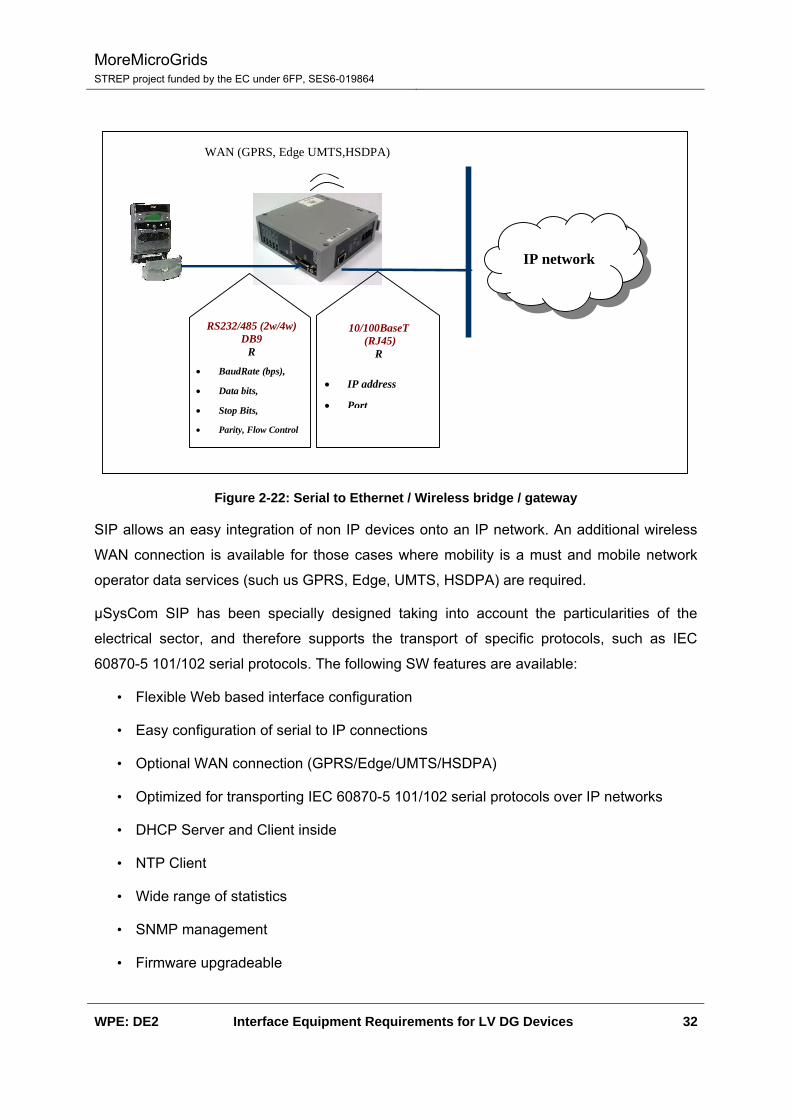
IP network
• IP address
• Port
• BaudRate (bps),
• Data bits,
• Stop Bits,
• Parity, Flow Control
RS232/485 (2w/4w) DB9
R
10/100BaseT (RJ45)
R
WAN (GPRS, Edge UMTS,HSDPA)
Figure 2-22: Serial to Ethernet / Wireless bridge / gateway
SIP allows an easy integration of non IP devices onto an IP network. An additional wireless
WAN connection is available for those cases where mobility is a must and mobile network
operator data services (such us GPRS, Edge, UMTS, HSDPA) are required.
µSysCom SIP has been specially designed taking into account the particularities of the
electrical sector, and therefore supports the transport of specific protocols, such as IEC
60870-5 101/102 serial protocols. The following SW features are available:
• Flexible Web based interface configuration
• Easy configuration of serial to IP connections
• Optional WAN connection (GPRS/Edge/UMTS/HSDPA)
• Optimized for transporting IEC 60870-5 101/102 serial protocols over IP networks
• DHCP Server and Client inside
• NTP Client
• Wide range of statistics
• SNMP management
• Firmware upgradeable

MoreMicroGrids STREP project funded by the EC under 6FP, SES6-019864
WPE: DE2 Interface Equipment Requirements for LV DG Devices 33
2.6. Software applications and miscellaneous
2.6.1. Energy management systems in electrical power distribution
Power management (Figure 2-23, Figure 2-24) in general implements the connection of
various energies (electricity, gas, water, heating, cooling, etc.) to various software packages.
Applications such as status visualization, consumption recording with the corresponding load
curve presentations and assignment to cost centres, load management, forecasts, as well as
reporting and control functions, recording and managing of maintenance information can be
implemented. A consistent operating and monitoring concept forms the basis for
comprehensive power management.
Figure 2-23: System structure for the communication in the energy distribution (Siemens)
A visualisation for event-oriented operating and monitoring is used at the level of low and
medium voltage electrical power distribution. All information about faults and events aids in
troubleshooting. Complete and detailed maintenance information is important for the
execution of maintenance works. The electrical power supply is monitored only with regard to
observance of limits and the switching of equipment (on- and off-switching). The electrical
energy demand is forecasted. All information and actions focus on smooth-free operation,
fast fault clearance, and the expedient execution of maintenance work.

MoreMicroGrids STREP project funded by the EC under 6FP, SES6-019864
WPE: DE2 Interface Equipment Requirements for LV DG Devices 34
Bus systems are used for the data transmission and communication in the electrical energy
distribution. This communication is not only used to record switch position, messages and
measurements, but also to perform switching operations. The communication with modern
circuit breakers allows a direct online parameterization of the setting values. Furthermore, all
recorded measured values can be read out.
Figure 2-24: Power management modules
Although a power management system is for sure not typical interface equipment as is the
issue of work package TE3 “interface equipment requirements”, but, this system demands
certain features from the hardware interface equipment of the network.
2.6.2. System Planning
Integral power system solutions are far more than just a combination of switchgear,
transformers, lines or cables, together with equipment for protection, supervision, control,
communication and whatever more. Of crucial importance for the quality of power
transmission and distribution is the integration of different components in an optimized
overall solution in terms of:

MoreMicroGrids STREP project funded by the EC under 6FP, SES6-019864
WPE: DE2 Interface Equipment Requirements for LV DG Devices 35
• System design and creative system layout, based on the load centre requirements and
the geographical situation
• Component layout, according to technical and economic assumptions and standards
• Operation performance, analyzing and simulation of system behaviour under normal
and fault conditions
• Protection design and coordination, matched to the power system.
Some of the tasks that have to be performed for system planning are depicted in Figure 2-25.
Figure 2-25: Tasks of system planning
2.6.3. Protection design and coordination
Apart from all the intelligence that is required to operate Microgrid networks basic tasks of
protection have to be applied:
• Protection of persons against the effects of short-circuits

MoreMicroGrids STREP project funded by the EC under 6FP, SES6-019864
WPE: DE2 Interface Equipment Requirements for LV DG Devices 36
• Protection of operational equipment from destruction and damages
• Maintaining the power system operation in case of failures
2.6.3.1. Principles of protection coordination
Relay operating characteristics and their setting must be carefully coordinated in order to
achieve selectivity. The aim is basically to switch off only the faulted component and to leave
the rest of the power system in service in order to minimize supply interruptions and to
assure stability (Figure 2-26). For this protection has to be:
• Fast (to avoid damage that is over proportional to time)
• Selective (switch off only faulted part)
• Sensitive (protection should be as sensitive as possible to detect faults at the lowest
possible current level) and
• Available (operation without any failure i.e. by digital protection with self-monitoring).
At the same time, however, it should remain stable under all permissible load, overload and
through-fault conditions.
Fast,more secure,and selective
protection system
Optimalprotection concept
Goodprotection devices
Precise setting
Precise commissioning
Regularcontrol:
Maintenance, check,self-monitoring
Fast,more secure,and selective
protection system
Optimalprotection concept
Goodprotection devices
Precise setting
Precise commissioning
Regularcontrol:
Maintenance, check,self-monitoring
Figure 2-26: Planning of power system protection
Aspects of protection coordination comprise:
• Selection and coordination of relay features by themselves
• Selection and coordination of relay features due to system devices, given
Network configuration and client
• Selective grading and parameterising of main and backup protection

MoreMicroGrids STREP project funded by the EC under 6FP, SES6-019864
WPE: DE2 Interface Equipment Requirements for LV DG Devices 37
• Application of tele-protection schemes ensuring fault clearance for 100% of protected
line and avoiding unselectivity
• CT- and VT-dimensioning according to relay requirements
With digital tools for network calculation it is necessary to perform steady state and transient
simulation of protection and power system such as calculation of important load flow
scenarios, voltage profiles (voltage drop ◊ U/I-fault detection), minimum and maximum short-
circuit currents and transient stability with maximum fault duration and relay-dead time).
Minimum short-circuit currents (two- and one-phase) and maximum load currents (minimum
load impedances) determine the pick-up values. Maximum short-circuit currents determine
the maximum permissible fault duration.
More generally it has to be taken into account:
• Which neutral earthing method?
• Which break times are permissible?
• Which target time at the supplies?
• How will the system develop in the future?
• How important are the customers?
• Which information is required?
2.6.3.2. Revision of conventional protection concepts for µGrid protection
µGrids are characterized by a high number of subunits connecting DG units to LV and MV
networks. As a consequence, conventional selective protection concepts lead to high fault
clearing times or unselective trippings which become unacceptable under operational and
economical aspects. A revision of conventional protection concepts i.e. with new protection
grading principles is necessary.
For ring networks with numerous subunits and converter connected DG and radial network
with direct connected DGs an investigation has shown that the use of inverse time
characteristics according to an advanced manner can lead to significant shorter delay times
ensuring selectivity simultaneously. The benefit becomes the more obvious the higher the
number of subunits which is typically for networks with DG infeed ([Ref-4]).
MoreMicroGrids STREP project funded by the EC under 6FP, SES6-019864
WPE: DE2 Interface Equipment Requirements for LV DG Devices 38
2.6.4. Engineering software
2.6.4.1. Network planning and dimensioning tools
For the planning of DG networks it is required to check whether the system supply conditions
are met. This requires, according to the conventional method, several calculations of the
different operational modes in order to determine the voltage drop with full respectively no
generation. An Automated examination of the voltage drop of DG plants would help to reduce
the effort considerably.
Moreover, the harmonic distortion of the system produced by DG plants has to be examined.
Not only the THD but also the content of the individual harmonics have to match the
requirements. This requires extensive examinations with a computer simulation program. An
Automated examination of the prospective harmonic distortion of DG plants combined with a
comparison with the requirements would be an interesting tool, therefore.
A combination of these tools: Automated examination of the voltage drop and automated
examination of the prospective harmonic distortion in form of an “electronic data sheet” of the
DG plant would further reduce the effort on necessary examination of such systems.
2.6.4.2. Support tool for selective protection settings
The determination of appropriate setting parameters for the protection equipment and
coordinating it with the higher-level protection requires relatively large effort when doing it
manually. An add-on on software exiting programs Automated protection setting for DG
plants would help to decrease the effort in cases where a standardized DG plant
configuration is to be examined.
MoreMicroGrids STREP project funded by the EC under 6FP, SES6-019864
WPE: DE2 Interface Equipment Requirements for LV DG Devices 39
3. Computer Aided Design Software Tools
This chapter focuses on the desirable features that should characterise computer aided
design tools used for electric power system installations. In general terms, several design
tasks could be considered as base for a detailed analysis, from HV/MV substation to MV/LV
industrial distribution substations but also extending into DER installations; as alternative a
group of different tasks are taken into account irrespectively of the concrete field to provide
an overview of the problem and identified needs.
3.1. Requirements overview
The general procedure for electrical installations design includes several distinct elements
summarised in:
• One-Line Schematics: This representation identifies the basic configuration of the
installation, how it is exploited, etc. Usually, the one line includes basic information
about the control system, protection relay codes, etc.
• Electrical engineering works general floor plan: It documents the physical layout of the
electrical equipment; for instance, in the case of a substation, bushings, incoming and
outgoing lines, transformers, switchgear, disconnectors, distances, auxiliary elements,
etc. are depicted in their physical locations in accordance to the adopted shape (U, L,
Y…).
• Civil engineering works floor plan: It covers the physical layout of the whole
installation: terrain, foundations, trenches for power, control & signalling cabling, oil
spill recovery trenches and tanks, sheltering elements, housing for in-door equipment,
security fences, etc.
From the theoretical point of view, the full integration of all involved processes would be
required but difficult to achieve. Floor plans for the general electrical and civil engineering are
relatively easy to merge in a single step because there is a large experience in the use of
CAD systems for building with several tools available (AutoCAD®).
The most outstanding feature of these applications devoted to support civil engineering is
based on the inclusion of high level objects and entities (i.e. door, wall, window, and so on)
with their own behaviour and managing rules.

MoreMicroGrids STREP project funded by the EC under 6FP, SES6-019864
WPE: DE2 Interface Equipment Requirements for LV DG Devices 40
The applications used for electrical engineering design are less mature and, in most cases,
each task has to be handled with a different software environment, material list end up in MS
Excel listings, graphical representations of the one-line, three-line schematics are just mere
plots with primitives (line, arc, box…) with no intelligence behind, relays are configured using
the manufacturer proprietary solution, etc.
Therefore, the general floor plans are left out of consideration, and the set of requirements
for an integrated tool supporting the electrical engineering part of the design phase are
targeted.
The general application is structured in modules that complement each other, each of the
considered modules contain other sub-modules. The proposed architecture is intended to be
indicative of one potential layout satisfying some functional requirements; other layouts are
also possible after a more detailed software specification is conducted.
3.2. Engineering Software
There are several electrical installations that could be taken as example for guiding a general
configuration, for instance, in case of an industrial installation feed from MV or a HV/MV
substation.
The first example is relatively simple: compact substations manufacturers (either global like
ABB, Schneider Electric, Siemens, etc. or either local such as Ormazabal at Spain…) supply
their customers with design supporting tools. This type of tools, provide, under a graphical
environment, help in the process to design the desired plant.
Figure 3-1 shows one of the outputs of amiKIT (see [www-9]) where the different cubicles of
the installation are outlined. The engineering design is relatively complicated because the
tool integrates the intelligence to guide the user along the process and deduces some
constraints from provided information (i.e. from the province: the local distribution company
name, available voltage levels and applicable constraints, etc. are derived).
In the particular case of this tool, estimated budget, list of materials, CAD drawings, project
drafts and other features are provided as well as export capacity into MS Office components.
In any case, the final project for the installation has to be adapted and reviewed by the
engineering or architecture company using the application.

MoreMicroGrids STREP project funded by the EC under 6FP, SES6-019864
WPE: DE2 Interface Equipment Requirements for LV DG Devices 41
Figure 3-1: AmiKIT19: Floor plant of HV metal clad cubicles
In summary, when the engineering tool is provided by a single company offering a complete
catalogue of solutions for every single need, it is possible to use it. Some elements are still
missing but the process is almost done.
When a larger project is aimed, when products and solutions from several purveyors are
required, when a more processes are involved, then some advanced application is needed.
This is the case of DER installations or substation design where local controls, interlocking
mechanisms, protection relays configuration, etc. are integrated in the project.
3.2.1. Environment
A brief analysis of the existent tools and their features demonstrates that although there are
applications managing the CAD part they do lack of support for advanced modelling, while
19 Customer support tool provided by Ormazabal for the Spanish market.
MoreMicroGrids STREP project funded by the EC under 6FP, SES6-019864
WPE: DE2 Interface Equipment Requirements for LV DG Devices 42
those integrating adequate data models do not include the graphical design part and
electrical engineering tasks.
3.2.1.1. CAD Tools
In the market there are many available tools for CAD, from the well knows AutoCAD® ([www-
4]), MicroStation® ([www-5]) to many other smaller products.
The interesting issue of general CAD applications is that some intelligence is built on top of
them to support advanced engineering tasks. The basic feature of any CAD application is
drawing through the use of basic plot primitives: lines, arcs, etc. completed with scaling,
multilayered views, hidden layers, and so on.
Over these basic elements, some domains have evolved these tools integrating some higher
level objects that improve significantly the engineering tasks. A clear example is architecture:
special modules are added on top of the basic CAD tool to provide access to entities such as
walls, doors, windows, etc. These advanced elements behave properly, if two walls are
crossed at the graphical interface there are not two separate walls any more, a corner is
automatically added, its properties defined considered walls width, etc.
In the electrical engineering domain something similar is found with a few products able of
handling single phase and three phase representations properly (AutoCAD Electrical,
Electrical Designer -[www-2]- and others) with more or less functionalities apart from the
basic drawing.
3.2.1.2. IEC 61850
IEC 61850 Standard was developed by WGs 10, 11 and 12 belonging to IEC Technical
Committee 57. These working groups focused on communications within substations, as
opposed to distributed Telecontrol, which was the focus of Working Group 3, or
communications between control centers, as in Working Group 7. Communications within the
substation were divided into three levels: station, process, and unit. Initially each Working
Group handled a different part of the architecture, but in later years they formed joint task
forces to address mutual issues. The initial specifications focused on a “top-down” approach,
characterizing the interactions between substation components at requirements level:
• 61850-1 Introduction and Overview
• 61850-2 Glossary
• 61850-3 General Requirements

MoreMicroGrids STREP project funded by the EC under 6FP, SES6-019864
WPE: DE2 Interface Equipment Requirements for LV DG Devices 43
• 61850-4 System and Product Management
• 61850-5 Communications Requirements
These WGs also had within their scope the task of developing a standard file format for
exchanging information between proprietary configuration tools for substation devices. This
standard is based on Extensible Markup Language (XML), and draws on the data modelling
concepts found in the other parts of IEC 61850, and the capability of the IEC 61850 protocols
to “self-describe” the data to be reported by a particular device.
• 61850-6 Substation Configuration Language
The IEC61850-7-420 standard has been recently published based on a previous work
distributed as “Utility Communications Architecture (UCA®) Object Models for Distributed
Energy Resources (UCA-DER)”
The IEC 61850-7-420 grows over the base established by the IEC 61850 standard taking the
logical node, logical device, common data classes and remaining available modelling entities
as base for the information models of several DER technologies.
• 61850-7-420 Communication systems for distributed energy resources (DER) – Logical
nodes
IEC 61850-7-420 is recent and there are not any tools supporting it, IEC 61850-6 is more
mature and there are applications as Visual SCL ([www-3]) or Kalki SCL Manager ([www-7])
integrating the standard data model.
Visual SCL is a graphical tool that implements the SCL standard allowing the engineer to
concentrate on the engineering of substation automation tasks instead on the concrete
details of the XML syntax. Objects representing busbars, transformers, etc. are directly
managed and placed on the single line representation.
Figure 3-2: VisualSCL single-line substation schematic

MoreMicroGrids STREP project funded by the EC under 6FP, SES6-019864
WPE: DE2 Interface Equipment Requirements for LV DG Devices 44
The SCL syntax is maintained, cross references established, attributes filled with ad-hoc
forms and some graphics functionalities introduced.
3.2.2. Requirements
The comparison between those tools aimed for CAD within the electrical domain and those
supporting the IEC 61850 offer a clear conclusion: it is easier to further develop CAD
applications up to cover the appearing needs than achieve an acceptable functionality on
SCL applications.
This approach is perfectly admissible because it exactly describes the traditional business
model for third parties developing add-ons for off-the-self CAD applications. The main CAD
product is customized by some external developer linked through a partnership program and
aims to a given, small or not, market niche.
A detailed review of the functionalities offered by AutoCAD® Electrical (Autodesk® product)
and those coming with third parties such as Electrical Designer reveals, apart from a clear
parallelism between both, the inclusion of advanced modules and tools able to manage
electrical projects.
3.2.2.1. Data Model
The IEC 61850 seems to be the new coming standard, not only for substation
communications but for some other applications (hydro power plants, wind farms, DER
plants …).
Those tools aimed to support the electrical engineering tasks integrated with CAD
environments have evolved a set of high level objects with integrated logic. These objects
are far more complex that the simple symbol libraries because they behave as single entities
with their own relations, characteristics... but are still far from providing the required levels of
intelligence.
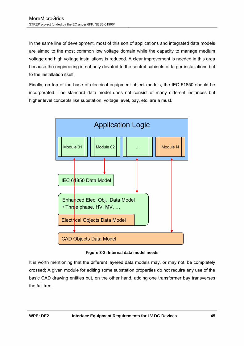
Figure 3-3 represents the layered scheme of complementary data models required for
advanced engineering tools. The base layer is composed by the traditional CAD primitives;
on top of this some basic electrical objects are represented.
This second tier requires some improvements: for instance, to enhance three phase proper
support depending on the source add-on used as base for development because AutoCAD®
Electrical management of three phase networks seems to be limited (only mentioned at
motor control module) while Electrical Designer handles three phase networks.
MoreMicroGrids STREP project funded by the EC under 6FP, SES6-019864
WPE: DE2 Interface Equipment Requirements for LV DG Devices 45
In the same line of development, most of this sort of applications and integrated data models
are aimed to the most common low voltage domain while the capacity to manage medium
voltage and high voltage installations is reduced. A clear improvement is needed in this area
because the engineering is not only devoted to the control cabinets of larger installations but
to the installation itself.
Finally, on top of the base of electrical equipment object models, the IEC 61850 should be
incorporated. The standard data model does not consist of many different instances but
higher level concepts like substation, voltage level, bay, etc. are a must.
IEC 61850 Data Model
Enhanced Elec. Obj. Data Model• Three phase, HV, MV, …
Electrical Objects Data Model
Enhanced Elec. Obj. Data Model• Three phase, HV, MV, …
Electrical Objects Data Model
CAD Objects Data Model
Application Logic
Module 01 Module 02 … Module N
Figure 3-3: Internal data model needs
It is worth mentioning that the different layered data models may, or may not, be completely
crossed; A given module for editing some substation properties do not require any use of the
basic CAD drawing entities but, on the other hand, adding one transformer bay transverses
the full tree.
MoreMicroGrids STREP project funded by the EC under 6FP, SES6-019864
WPE: DE2 Interface Equipment Requirements for LV DG Devices 46
3.2.2.2. Data Storage
No special requirement is defined for the data repository. It is assumed that relational data
bases (RDB) are in use as they are in today tools and applications.
This approach based on conventional and well matured RDB for providing the back end data
storage is aimed to allow easy access to data, externalize the storage format issue and
provide an entry point for the integration with other corporative modules. An integrated set of
relations between tables, primary keys and other RDB management facilities contribute the
overall data organization and coordination.
3.2.3. Modules
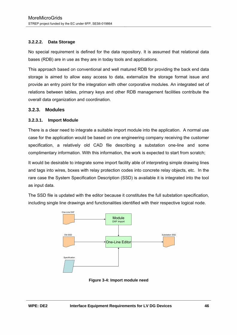
3.2.3.1. Import Module
There is a clear need to integrate a suitable import module into the application. A normal use
case for the application would be based on one engineering company receiving the customer
specification, a relatively old CAD file describing a substation one-line and some
complimentary information. With this information, the work is expected to start from scratch;
It would be desirable to integrate some import facility able of interpreting simple drawing lines
and tags into wires, boxes with relay protection codes into concrete relay objects, etc. In the
rare case the System Specification Description (SSD) is available it is integrated into the tool
as input data.
The SSD file is updated with the editor because it constitutes the full substation specification,
including single line drawings and functionalities identified with their respective logical node.
One-Line DXF
ModuleDXF Import
Old SSD
One-Line Editor
Substation SSD
Specification
Figure 3-4: Import module need

MoreMicroGrids STREP project funded by the EC under 6FP, SES6-019864
WPE: DE2 Interface Equipment Requirements for LV DG Devices 47
3.2.3.2. Design Modules
The engineering tasks included into the basic application are developed as individual
modules to provide the maximum flexibility.
Following the substation design case: the SSD data is completed with existent products
taken from off-line or on-line catalogues, IED capability files should be integrated to assign a
given logical device to a physical device, other data as customer preferences should be
treated and incorporated to the final model, IED configured into Configured IED Description
(CID). As result of many sequential and simultaneous processes the final Substation
Configuration Description (SCD) is obtained.
Editor
Substation SSD
Equipment DB
Substation SCD
Other data
ICD Files
Wiring Schemas:
• Physical & Logical
• Communications, Signals, Power, …
Module …
Module 02
Module 01
Figure 3-5: Some targets for the installation electrical engineering
This IEC 61850 specified file is just part of the overall design because there are many other
tasks that are required to implement such a specification:
- Catalogue of HV, MV and LV products
- Terminals require labelling, automatic numbering, error checking, physical layout in
cabinets or trenches, etc.
- Terminals are integrated into cables, also requiring labelling, numbering, etc.
- PLC I/O design, ladder programming, export to some sort of format understood by the
PLC and even import capacity from PLC into the database.

MoreMicroGrids STREP project funded by the EC under 6FP, SES6-019864
WPE: DE2 Interface Equipment Requirements for LV DG Devices 48
- Wires may belong to the electrical system, to the auxiliary power system, to control
system, to communications network, etc.
- …
Above list is not intended to provide a complete relation of modules, functionalities or needs;
it just aims to outline some concurrent issues.
For most of the cases (substation design, DER plant design, etc.) there is a need to
configure the IEDs; this information is built from the IED capability file, completed with the
local utility and produces the IED configuration files (CID) as seen in Figure 3-6.
IEDIED
Substation SSD
Substation SCD File
CID files
EditorICD files
Export / Import
IED
Communication to remote device
Customer Specification
Figure 3-6: IED configuration edition
Logically this information belongs to the complete SCD model but needs to be extracted from
it and transferred back to the IED providing the service. This second step requires a special
care for medium term maintenance (Figure 3-7) of the SCD file because any change
performed on the local installation may remain hidden producing unexpected results in case
of later updates to the IED.

MoreMicroGrids STREP project funded by the EC under 6FP, SES6-019864
WPE: DE2 Interface Equipment Requirements for LV DG Devices 49
IEDIED
Substation SSD
Substation SCD File
CID files
EditorICD files
Export / Import
IED
Communication to remote device
Customer Specification
Figure 3-7: IED configuration maintenance
3.2.3.3. Data Editors
The engineering process includes not only the design of the installation, cablings, controls,
etc. but also involves the selection of specific equipment able to satisfy a given requirement.
Libraries
Editor
• ANSI
• IEC
• …
• DIN
• …
Figure 3-8: Library editor
These requirements could be as simple as the set of symbols preferred by the final customer
(ANSI, IEC, etc. or even custom) managed by means of external libraries (Figure 3-8).
The specification defines functional requirements and it could be incorporated to the project
in terms of engineering. For instance one instantaneous over-current function may be
needed, and the connections from the relay function to the current transformer and to the

MoreMicroGrids STREP project funded by the EC under 6FP, SES6-019864
WPE: DE2 Interface Equipment Requirements for LV DG Devices 50
breaker may be added to the project. These elements, type, characteristics, etc. also form
part of the overall project and should be specified.
Catalogue • Technical Data
• Physical Data
• Connectivity Data
• Price Data
• ICD
• …
Editor
Figure 3-9: Catalogue editor
Figure 3-9 depicts a catalogue editor that allows considering different products from distinct
purveyors. It is worth noticing that the type of data hold by the catalogue will vary depending
on the features of the software tool.
Substation equipment ICD data is required to complete the IEC 61850 set of files but
connectivity data would be required if advanced coherence wiring checking is done, physical
sizes if cabinet layouts are considered as part of the outcomes.
3.2.3.4. Documentation modules
In the same way that design application is built as a group of concurrent modules,
documentation applications is also formed by several compatible modules in charge of
generating the different elements that constitute the installation information:
- Bill of Materials: This report may be based on mere plain text listing or more
complicated word processor formats (rtf…) with properly designed templates.
- CAD Drawings: High level single phase schematics, detailed single phase schematics,
three phase, cabinet deployment layouts, etc.
- IEC 61850 related files: SCD, IDC, SSD…
- Others like wire labels, wire lists, cable lists, etc.
- …

MoreMicroGrids STREP project funded by the EC under 6FP, SES6-019864
WPE: DE2 Interface Equipment Requirements for LV DG Devices 51
Project Data CatalogueLibraries
Bill Of Materials- Engine -
Templates BoM {.txt, .rft, …}
Templates DXF / DGN / DWG / …
Templates SCD / SSD / ICD / …
…- Engine -
Templates Part List / Connection List / …
…- Engine -…
- Engine -
CAD Drawing- Engine -
IEC 61850- Engine -
Figure 3-10: Documentation modules
It is worth noticing that, in case the database internal design is accessible and documented,
some, if not most, of these documentation modules could be based on existent third party
tools and applications (i.e. Crystal Reports®).
3.2.4. Other modules
The whole software package would be completed with some additional components aimed to
help during the engineering process such as:
3.2.4.1. Error checking
A significant part of the effort during the engineering phase is applied to the correction of
errors, specially when several task are executed in parallel. One-supposed-to-be-small
change may derive into serious consequences in other parts of the project or, even worse,
remain hidden until a latter stage.
MoreMicroGrids STREP project funded by the EC under 6FP, SES6-019864
WPE: DE2 Interface Equipment Requirements for LV DG Devices 52
In this sense, there is a clear need for tools in charge of checking automatically for errors,
ensuring the coherence across all the concurrent development lines. These tools may be
based on simple searches for duplicate entries to more complex pattern matching, from
accounting the number of free terminals on a given device to the number of wires in a single
cable, in any case there will always be something susceptible to be verified.
In general terms, each company experience and internal organization may lead to slightly
different needs in terms of data assessment that could be solved applying custom modules
to the database data.
3.2.4.2. Layout
Some commercially available products offer some sort of automatic layout engine able to
help into producing the cabinet wiring layout. So far, this type of applications are quite
immature but complex electrical engineering designs need to define the internal (cabinets)
and external (other elements) layouts of various systems: communication (physical layers),
power, control, signals, etc.
3.2.4.3. Repository
A consistent repository management module is clearly foreseen; on one hand, the learning
effort resulting from the introduction of a new software tool for electrical engineering is only
compensated after several years, when designers are fully used to the application and
provide the maximum performance using it; on the other hand, developed projects for the
same customer are likely to be quite similar in terms of specification and this leads to the fact
that several projects will share philosophy (protective relay scheme, signalling…).
Therefore, it is clear that, following the new design integrated application, there will grow a
large know-how database, suitable to be exploited with some form of copy-paste of
components. The coherence checking modules will assist the engineering team to early
correct any made mistake.
MoreMicroGrids STREP project funded by the EC under 6FP, SES6-019864
WPE: DE2 Interface Equipment Requirements for LV DG Devices 53
4. References
[Ref-1] Siemens AG, Totally integrated power, second revision edition, Siemens AG,
Berlin and Munich, Germany, 2005.
[Ref-2] Trench, Brochure Reactors, Canada, 2006
[Ref-3] C.Nietsch, C. Schwaegerl et al.: ‘Netzverträglichkeit von PV-Kraftwerken’, OTTI PV
Kloster Banz, 2007
[Ref-4] J. Jäger, T. Keil, L. Shang, R. Krebs: ‘New protection coordination methods in the
presence of distributed generation’, IEE Amsterdam, 2004
[Ref-5]
MoreMicroGrids STREP project funded by the EC under 6FP, SES6-019864
WPE: DE2 Interface Equipment Requirements for LV DG Devices 54
5. Web Sites
[www-1] http://www.abb.com/
[www-2] http://www.aceri.com/
[www-3] http://www.ase-systems.com/
[www-4] http://www.autodesk.com/
[www-5] http://www.bentley.com/
[www-6] http://www.iec.ch/ International Electrotechnical Commission – IEC
[www-7] http://www.kalkitech.com/
[www-8] http://www.schneider-electric.com/
[www-9] http://www.ormazabal.com/
[www-10] http://www.siemens.com/
[www-11] http://www.ziv.es/
[www-12] http://jade.tilab.com/

MoreMicroGrids STREP project funded by the EC under 6FP, SES6-019864
WPE: DE2 Interface Equipment Requirements for LV DG Devices 55
6. Glossary
Term Stands for Notes
CAMC Central Autonomous Management Control
More µGrids project term defining an intermediate control hierarchy bellow the DMS.
CID Configured IED Description
DG Distributed Generation
DMS Distribution Management System
DSP Digital Signal Processor
EMC Electromagnetic compatibility
FACTS Flexible AC transmission systems
GPS Global Positioning System
HRC High Rupturing Capacity
HV High Voltage
ICD IED Capability Description File based on SCL
IEC International Electrotechnical Commission
IED Intelligent Electronic Device
ILC Intelligent Load Controller
IP Internet Protocol
One of the stacked protocols at TCP/IP networks; Used in general to identify the whole set of protocols and associated functionality
IPsec IP Security Standard for authentication and encryption over IP.
JADE Java Agent DEevelopment Framework
JADE-LEAP JADE Light Extensible Agent Platform Reduced version of JADE platform aimed towards embedded –limited– devices.
JVM Java Virtual Machine
LAN Local Area Network
LV Low Voltage
MAS Multi-Agent System
MV Medium Voltage
MGCC MicroGrid Central Controller Energy management system in charge of controlling a µGrid as to fulfil any given target.
NTP Network Time Protocol

MoreMicroGrids STREP project funded by the EC under 6FP, SES6-019864
WPE: DE2 Interface Equipment Requirements for LV DG Devices 56
Term Stands for Notes PLC Power Line Communications
PR Performance Ratio
PV Photo Voltaic
PWM Pulse Width Modulation i.e. for motor speed control
RDB Relational Data Base
RFC Request for Comments IEEE term.
SCD Substation Configuration Description File based on SCL
SCL Substation Configuration Language IEC 61850-6 Standard
SPD Surge Protection Device
SSD System Specification Description File based on SCL
THD Total Harmonic Distortion
VPM Virtual Private Network
VSI Voltage Source Inverter
WAN Wide Area Network

MoreMicroGrids STREP project funded by the EC under 6FP, SES6-019864
WPE: DE2 Interface Equipment Requirements for LV DG Devices 57
7. Annexes
7.1. Annex A: Network integration of a 5 MW solar park
7.1.1. Introduction
In 2004, one of the world’s biggest PV-plants with 5 MWp electric power was built close to
Leipzig in Germany. GEOSOL, Shell Solar, Siemens and West Fonds constructed the
“Solarpark Leipziger Land” on a coal dust landfill. This solar park has a total surface area of
16 hectares and comprises 33,264 solar modules.
During the last years the number of bigger PV-plants (>1 MVA) has increased significantly.
The infeed of generating power from PV-plants with installed capacities of more than 5 MW
possibly alters the direction of power flow and takes considerable influence on the local
network quality.
7.1.2. Idea
Due to the restricted bearing capacity of the soil in this coal dust deposit, the location of the
containers was transferred to the outer sides of the basin and the 20kV substation was
placed outside this area. Four inverter containers with 3 x 400kVA SINVERT solar M/S/S
inverters each take in the PV-input of 2 x 1.25MVA transformer stations at one site and feed
into the 20kV system via decentralized located 20/0.4kV transformers (Figure 7-1).
Figure 7-1: Solarpark Leipziger Land

MoreMicroGrids STREP project funded by the EC under 6FP, SES6-019864
WPE: DE2 Interface Equipment Requirements for LV DG Devices 58
In the 20kV switchgear building located outside the basin, the circuit breakers with
transformer feeder protection, the 20kV connection with measuring system and the 20/0.4 kV
station-service transformer of 50KVA, as well as the control via intelligent SIPROTEC
protection and bay controller devices have been installed (Figure 7-2).
20 kV Schaltanlage
DC Netz
3x 400 kWM / S / S
EB_Trafo (50 kVA)
M
NS-Messung
Leis
tung
ssch
alte
r m
it U
MZ-
Schu
tz
Block_Trafo 1 (2,0 MVA)
M MS-Messung
Block_Trafo 2 (2,0 MVA)
SIPROTEC
SIPROTEC
20 k
V N
etza
nbin
dung
envi
a
WR_Container 1.1
1,25 MWp
1,25 MWp
WR_Container 1.2
WR_Container 2.1
1,25 MWp
1,25 MWp
WR_Container 2.2
=
=
=
=
3x 400 kWM / S / S
3x 400 kWM / S / S
3x 400 kWM / S / S
DC Netz
DC Netz
DC Netz
Solargeneratoren
Solargeneratoren
Solargeneratoren
Solargeneratoren
Figure 7-2: PV plant conception
7.1.3. Technology and Operation
The PV-plant has been equipped with twelve SINVERT solar 400 inverters in master-slave
operation, which directly feed on two 20/0.4kV GEAFOL transformers (2 MVA). The
intelligent controlling of inverters and a central SIMATIC control system ensure the
compatibility of PV-power infeed with the network, see Figure 7-3 [Ref-3]:
• Phase-symmetry control ensures the symmetric infeed into the system; avoidance of
negative-sequence and zero-sequence systems
• Cosφ control backs the voltage quality on site and, if required, provides capacitive or
inductive reactive power
• VAr control
• The active harmonic current control reduces the harmonic current load on the
connecting point and renders possible a higher PV-input even in pre-loaded systems
• Automatic overnight disconnection via the SIMATIC/SIPROTEC control system
reduces losses and increases the overall efficiency (Performance Ratio PR) of the PV-
plant
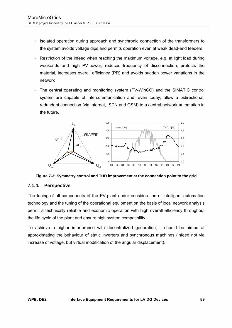
MoreMicroGrids STREP project funded by the EC under 6FP, SES6-019864
WPE: DE2 Interface Equipment Requirements for LV DG Devices 59
• Isolated operation during approach and synchronic connection of the transformers to
the system avoids voltage dips and permits operation even at weak dead-end feeders
• Restriction of the infeed when reaching the maximum voltage, e.g. at light load during
weekends and high PV-power, reduces frequency of disconnection, protects the
material, increases overall efficiency (PR) and avoids sudden power variations in the
network
• The central operating and monitoring system (PV-WinCC) and the SIMATIC control
system are capable of intercommunication and, even today, allow a bidirectional,
redundant connection (via internet, ISDN and GSM) to a central network automation in
the future.
UL1
UL2 UL3
gridSINVERT
ΔU0
0
100
200
300
400
500
00 02 04 06 08 10 12 14 16 18 20 22 240,0
0,4
0,8
1,2
1,6
2,0
power [kW] THD U [% ]
Figure 7-3: Symmetry control and THD improvement at the connection point to the grid
7.1.4. Perspective
The tuning of all components of the PV-plant under consideration of intelligent automation
technology and the tuning of the operational equipment on the basis of local network analysis
permit a technically reliable and economic operation with high overall efficiency throughout
the life cycle of the plant and ensure high system compatibility.
To achieve a higher interference with decentralized generation, it should be aimed at
approximating the behaviour of static inverters and synchronous machines (infeed not via
increase of voltage, but virtual modification of the angular displacement).
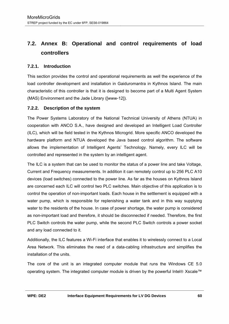
MoreMicroGrids STREP project funded by the EC under 6FP, SES6-019864
WPE: DE2 Interface Equipment Requirements for LV DG Devices 60
7.2. Annex B: Operational and control requirements of load controllers
7.2.1. Introduction
This section provides the control and operational requirements as well the experience of the
load controller development and installation in Gaiduromantra in Kythnos Island. The main
characteristic of this controller is that it is designed to become part of a Multi Agent System
(MAS) Environment and the Jade Library ([www-12]).
7.2.2. Description of the system
The Power Systems Laboratory of the National Technical University of Athens (NTUA) in
cooperation with ANCO S.A., have designed and developed an Intelligent Load Controller
(ILC), which will be field tested in the Kythnos Microgrid. More specific ANCO developed the
hardware platform and NTUA developed the Java based control algorithm. The software
allows the implementation of Intelligent Agents’ Technology. Namely, every ILC will be
controlled and represented in the system by an intelligent agent.
The ILC is a system that can be used to monitor the status of a power line and take Voltage,
Current and Frequency measurements. In addition it can remotely control up to 256 PLC A10
devices (load switches) connected to the power line. As far as the houses on Kythnos Island
are concerned each ILC will control two PLC switches. Main objective of this application is to
control the operation of non-important loads. Each house in the settlement is equipped with a
water pump, which is responsible for replenishing a water tank and in this way supplying
water to the residents of the house. In case of power shortage, the water pump is considered
as non-important load and therefore, it should be disconnected if needed. Therefore, the first
PLC Switch controls the water pump, while the second PLC Switch controls a power socket
and any load connected to it.
Additionally, the ILC features a Wi-Fi interface that enables it to wirelessly connect to a Local
Area Network. This eliminates the need of a data-cabling infrastructure and simplifies the
installation of the units.
The core of the unit is an integrated computer module that runs the Windows CE 5.0
operating system. The integrated computer module is driven by the powerful Intel® Xscale™
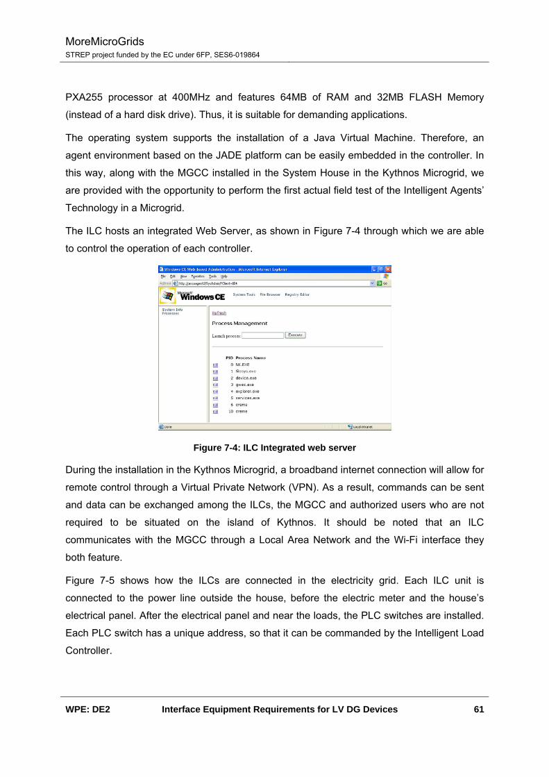
MoreMicroGrids STREP project funded by the EC under 6FP, SES6-019864
WPE: DE2 Interface Equipment Requirements for LV DG Devices 61
PXA255 processor at 400MHz and features 64MB of RAM and 32MB FLASH Memory
(instead of a hard disk drive). Thus, it is suitable for demanding applications.
The operating system supports the installation of a Java Virtual Machine. Therefore, an
agent environment based on the JADE platform can be easily embedded in the controller. In
this way, along with the MGCC installed in the System House in the Kythnos Microgrid, we
are provided with the opportunity to perform the first actual field test of the Intelligent Agents’
Technology in a Microgrid.
The ILC hosts an integrated Web Server, as shown in Figure 7-4 through which we are able
to control the operation of each controller.
Figure 7-4: ILC Integrated web server
During the installation in the Kythnos Microgrid, a broadband internet connection will allow for
remote control through a Virtual Private Network (VPN). As a result, commands can be sent
and data can be exchanged among the ILCs, the MGCC and authorized users who are not
required to be situated on the island of Kythnos. It should be noted that an ILC
communicates with the MGCC through a Local Area Network and the Wi-Fi interface they
both feature.
Figure 7-5 shows how the ILCs are connected in the electricity grid. Each ILC unit is
connected to the power line outside the house, before the electric meter and the house’s
electrical panel. After the electrical panel and near the loads, the PLC switches are installed.
Each PLC switch has a unique address, so that it can be commanded by the Intelligent Load
Controller.
MoreMicroGrids STREP project funded by the EC under 6FP, SES6-019864
WPE: DE2 Interface Equipment Requirements for LV DG Devices 62
Figure 7-5: Typical installation of an ILC Unit
7.2.3. Power Line Measurements
The Intelligent Load Controller built-in software provides the following functionalities
regarding the power line measurements:
• Frequency measurement.
• Voltage RMS measurement.
• Current RMS measurement.
• Sag events detection and announcement.
• Over-voltage events detection and announcement.
• Over-current events detection and announcement.
The values are calculated by sampling the power line at a rate of 3,500 SPS
(samples/second). As far as the events detection functionalities are concerned, the controller
announces the event start and termination, records the duration of the event and, depending
on the event, records the maximum or minimum value measured. It is important that, with the
software we have developed, the controller is capable of processing these measurements.
As a result, the agent who is implemented in the controller is able to identify only certain
events, take the relevant actions.
7.2.4. Operational Requirements
7.2.4.1. Environment
The controller is designed mainly for outdoor usage therefore it should take into account any
regulation that is related with external usage of electrical equipment. We have considered
two main issues:
• Water/humidity resistance
• Temperature
MoreMicroGrids STREP project funded by the EC under 6FP, SES6-019864
WPE: DE2 Interface Equipment Requirements for LV DG Devices 63
The outdoor installation near the sea requires capability of IP65 insulation against humidity
and rain, however the extreme temperatures in the Greek islands (>40º) should also be
considered.
7.2.4.2. Electrical Network
The controller is designed to operate not only to grid-connected mode but also to island
mode like the network in the island of Kythnos. This means that is should operate in voltage
and frequency levels that are not often in the ordinary grids. Especially regarding frequency a
value between 52-53 Hz is quite common in this network especially in case Gaidouromantra
when the batteries are full, the PV has full production and there is no load. Regarding voltage
quality and voltage dips we have not noticed any specific problem and the only requirement
is to be able to handle voltage levels and dibs that are acceptable by the local regulations.
7.2.4.3. Platform
The core of the software will be the Jade Library therefore the controller should have load the
proper Java Virtual Machine (JVM). Furthermore the Jade-Leap library has been used.
7.2.4.4. Communication
The java based library is using TCP/IP protocol for the communication and the physical
mean should be the most appropriate according to each installation. For example in the
Kythnos application Wi-Fi has been used.
7.2.5. Control requirements
7.2.5.1. Load Control
The load controller is using PLC switches that can handle up to 16A load. For the Kythnos
Island this is the absolutely acceptable however for other application this might create
limitations and can be solved by using an intermediate relay however this way the current
measurements do not reflect the actual load. Furthermore there are limitations on the current
the DSP processor can measure.
7.2.5.2. Measurements
As mentioned before the ILC is capable of measuring various values as well sag and over-
limit events. However within our application the events have been used only in the
laboratory. This is a part of the future work since not only fast dialogues are needed but also
different algorithmic approach introducing preventive operation.

MoreMicroGrids STREP project funded by the EC under 6FP, SES6-019864
WPE: DE2 Interface Equipment Requirements for LV DG Devices 64
7.2.5.3. Response time
The application was developed in the MAS principle of operation using Java, however this
creates problems in response times. The average response time if the system taking into
account that there might be some negotiation dialogues between the agents is approximately
1-2 sec. in order to achieve better response duration different approach should be selected
avoiding JVM.
7.2.6. Conclusion
The ILC controller has a suitable configuration for the test field in Gaidouromandra, however
in order to use it in different applications certain modifications modification should be done.
The most important are:
• The controller should be flexible enough to handle various loads
• The capability to achieve fast response times may require modification in the usage of
the Jade as well the adopted algorithmic approach.
MoreMicroGrids STREP project funded by the EC under 6FP, SES6-019864
WPE: DE2 Interface Equipment Requirements for LV DG Devices 65
7.3. Annex C: Electrical Designer description
7.3.1. ELECTRICAL Designer Current Version: 2008
Developer: ACERI S.A.
Country: Spain
Categories: Electrical; Electronic Schematics
Product Summary: Ideal software for electrical engineering design and drafting.
Product Language(s): Chinese, Dutch, English, French, German, Korean, Portuguese,
Spanish, Russian
Works With: AutoCAD 2008; AutoCAD Electrical 2008; AutoCAD 2007; AutoCAD 2006;
AutoCAD Electrical 2007; AutoCAD 2005
Price: Contact Developer
7.3.2. Target Customers
Engineering companies
Cabinets and panels builders and mounters
Electricity companies (manufacturers and transformers)
Automation companies
Large facilities maintenance
Process and power companies
Machine builders
7.3.3. Product Description
ELECTRICAL Designer is the ideal software for electrical engineering design and drafting
within AutoCAD®. It is easy to install, learn and use and with its dedicated electrical
engineering functions. ELECTRICAL Designer gives the user a better quality of drawings
supported by extensive documentation and error checking facilities. Drawings are produced
more quickly, efficiently and with a greatly reduced risk of costly errors. It includes as
standard, ANSI, BS, IEC, DIN and JIC libraries.

MoreMicroGrids STREP project funded by the EC under 6FP, SES6-019864
WPE: DE2 Interface Equipment Requirements for LV DG Devices 66
7.3.3.1. Main Features:
Project, Library and Catalogue Management
User-definable automatic numbering of circuit elements, wires and terminals.
Cross Reference Analysis.
Automatic generation of bills of materials, parts lists and connections lists.
Technical data reannotation into drawings
Semi-automatic generation of cabinet layouts
Automatic generation of terminal Drawings
Automatic drawing plotting
Terminals and Cables Editor
Connections and Terminals Lists
Libraryshow
Customisable by users
Uses standards (dbf and dwg files)
7.3.4. Benefits
Easy to learn and operate, fast Return On Investment
Improves drawing quality and productivity
Produces superior quality drawings and documentation.
Reduces risk of costly and time consuming design errors.
Information is produced in standards formats: DWG & DBF files
Connection to materials databases
Management and Project Control
Extensive schematics components and panels libraries supplied.
7.3.5. Features
Project, Library and Catalogue Management
User-definable automatic numbering of circuit elements, wires and terminals.
MoreMicroGrids STREP project funded by the EC under 6FP, SES6-019864
WPE: DE2 Interface Equipment Requirements for LV DG Devices 67
On-line Cross Reference Analysis.
Automatic generation of bills of materials, parts lists and connections lists.
Technical data annotation within drawings
Semi-automatic generation of cabinet layouts
Automatic generation of terminal Drawings
Point to point connections and Terminals Lists
Automatic drawing plotting
Terminal and Cable Editing
Library shows
7.3.6. Industry Standards
ANSI, DIN, IEC, BS, JIC, NEN and others
7.3.7. Documentation
Box: A box including users manual & tutorial manual, as well as the CD including the
software and the electronic tutorial
Download: Complete software & sample data. Complete documentation in PDF format.
Tutorials both in PDF and AVI formats.
7.3.8. Relation to Autodesk Products
Works With: AutoCAD® 2008 - 2007 - 2006 - 2005 - 2004 - 2002.
Version for AutoCAD LT® releases available.
7.3.9. Support and Training
http://www.aceri.com/cont/usuarios/ingreso_eng.php
7.3.10. Where to Buy
This product may be purchased online.
It is also available directly from the developer -- call +34 934531206 or visit
http://www.aceri.com.

MoreMicroGrids STREP project funded by the EC under 6FP, SES6-019864
WPE: DE2 Interface Equipment Requirements for LV DG Devices 68
Or visit http://www.aceri.com for a list of dealers through whom this product may be
purchased.