Embed Size (px)
Citation preview

Advanced Building Skins
10-11 October 2016, Bern, Switzerland
11th Conference on Advanced Building Skins
10-11 October 2016, Bern, Switzerland
ISBN: 978-3-98120539-8
Advanced Building Skins GmbHHostettstr. 30CH-6062 Wilen (Sarnen)Switzerland
VAT: CHE-383.284.931
Tel: +41 41 508 [email protected]
© Copyright: Advanced Building Skins GmbH
Reinforced, insulated glazing for large windows
Marc Donzé1, Maurice Brunner2, Urs Uehlinger3 1,2,3 Research and Development; Architecture, Wood, and Civil Engineering; Bern University of
Applied SciencesSolothurnstrasse 102, 2504 Biel, Switzerland, [email protected]
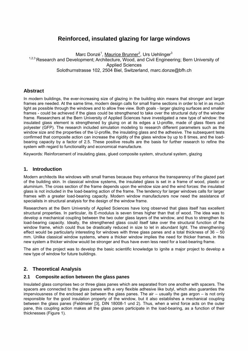
Abstract
In modern buildings, the ever-increasing size of glazing in the building skin means that stronger and largerframes are needed. At the same time, modern design calls for small frame sections in order to let in as muchlight as possible through the windows and to allow free view. Both goals - larger glazing surfaces and smallerframes - could be achieved if the glass could be strengthened to take over the structural duty of the windowframe. Researchers at the Bern University of Applied Sciences have investigated a new type of window: theinsulated glass element is strengthened by gluing on at its edges a U-profile, made of glass fibers andpolyester (GFP). The research included simulation modeling to research different parameters such as thewindow size and the properties of the U-profile, the insulating glass and the adhesive. The subsequent testsconfirmed that composite action can increase the rigidity of the glass window by up to 8 times, and the load-bearing capacity by a factor of 2.5. These positive results are the basis for further research to refine thesystem with regard to functionality and economical manufacture.
Keywords: Reinforcement of insulating glass, glued composite system, structural system, glazing
1. Introduction
Modern architects like windows with small frames because they enhance the transparency of the glazed partof the building skin. In classical window systems, the insulated glass is set in a frame of wood, plastic oraluminium. The cross section of the frame depends upon the window size and the wind forces: the insulatedglass is not included in the load-bearing action of the frame. The tendency for larger windows calls for largerframes with a greater load-bearing capacity. Modern window manufacturers now need the assistance ofspecialists in structural analysis for the design of the window frame.
Researchers at the Bern University of Applied Sciences have long observed that glass itself has excellentstructural properties. In particular, its E-modulus is seven times higher than that of wood. The idea was todevelop a mechanical coupling between the two outer glass layers of the window, and thus to strengthen itsload-bearing capacity. Ideally, the strengthened glass could itself take over the structural function of thewindow frame, which could thus be drastically reduced in size to let in abundant light. The strengtheningeffect would be particularly interesting for windows with three glass panes and a total thickness of 36 – 50mm. Unlike classical window systems, where a thicker window implies the need for thicker frames, in thisnew system a thicker window would be stronger and thus have even less need for a load-bearing frame.
The aim of the project was to develop the basic scientific knowledge to ignite a major project to develop anew type of window for future buildings.
2. Theoretical Analysis
2.1 Composite action between the glass panes
Insulated glass comprises two or three glass panes which are separated from one another with spacers. Thespacers are connected to the glass panes with a very flexible adhesive like butyl, which also guaranties theimperviousness of the enclosed air between the glass panes. The air – usually the gas argon – is not onlyresponsible for the good insulation property of the window, but it also establishes a mechanical couplingbetween the glass panes (Feldmeier [3], DIN 18008-1 und 2). Thus, when a wind force acts on the outerpane, this coupling action makes all the glass panes participate in the load-bearing, as a function of theirthicknesses (Figure 1).
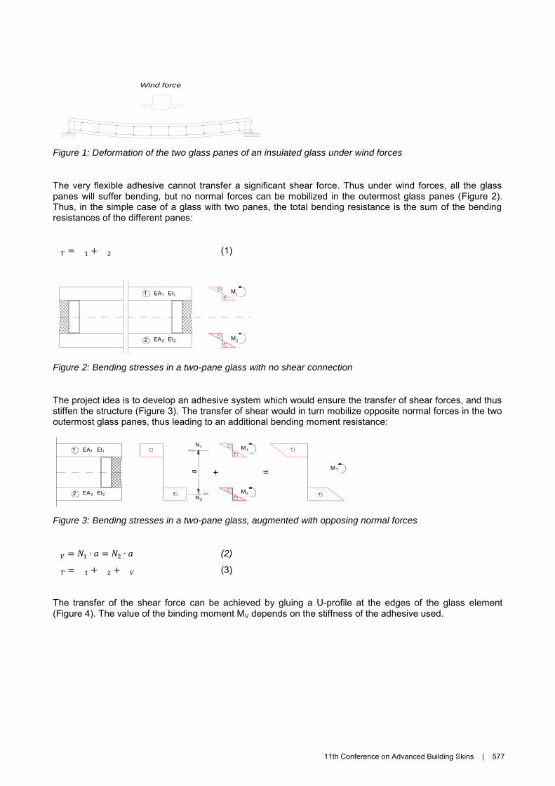
Figure 1: Deformation of the two glass panes of an insulated glass under wind forces
The very flexible adhesive cannot transfer a significant shear force. Thus under wind forces, all the glasspanes will suffer bending, but no normal forces can be mobilized in the outermost glass panes (Figure 2).Thus, in the simple case of a glass with two panes, the total bending resistance is the sum of the bendingresistances of the different panes:
(1)
Figure 2: Bending stresses in a two-pane glass with no shear connection
The project idea is to develop an adhesive system which would ensure the transfer of shear forces, and thusstiffen the structure (Figure 3). The transfer of shear would in turn mobilize opposite normal forces in the twooutermost glass panes, thus leading to an additional bending moment resistance:
Figure 3: Bending stresses in a two-pane glass, augmented with opposing normal forces
(2)
(3)
The transfer of the shear force can be achieved by gluing a U-profile at the edges of the glass element(Figure 4). The value of the binding moment MV depends on the stiffness of the adhesive used.
Wind force
M-
+
M-
+
EA1
2
1 EI1
EA2 EI2
1
2
+
M-
+
M-
+
-
+
N
N
= M
-
+
EA1
2
1 EI1
EA2 EI2
1
2
1
2
T
11th Conference on Advanced Building Skins | 577
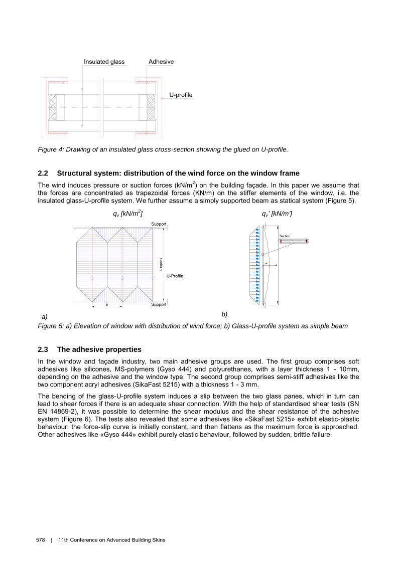
Figure 4: Drawing of an insulated glass cross-section showing the glued on U-profile.
2.2 Structural system: distribution of the wind force on the window frame
The wind induces pressure or suction forces (kN/m2) on the building façade. In this paper we assume that the forces are concentrated as trapezoidal forces (KN/m) on the stiffer elements of the window, i.e. theinsulated glass-U-profile system. We further assume a simply supported beam as statical system (Figure 5).
qv [kN/m2] qv’ [kN/m’]
a) b)
Figure 5: a) Elevation of window with distribution of wind force; b) Glass-U-profile system as simple beam
2.3 The adhesive properties
In the window and façade industry, two main adhesive groups are used. The first group comprises softadhesives like silicones, MS-polymers (Gyso 444) and polyurethanes, with a layer thickness 1 - 10mm,depending on the adhesive and the window type. The second group comprises semi-stiff adhesives like thetwo component acryl adhesives (SikaFast 5215) with a thickness 1 - 3 mm.
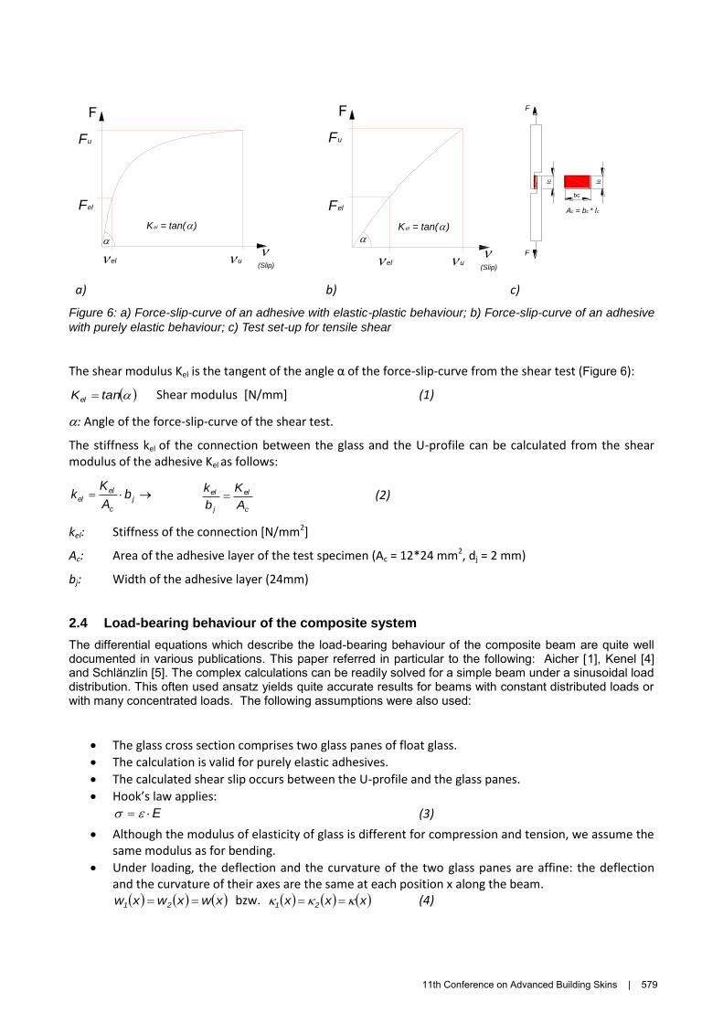
The bending of the glass-U-profile system induces a slip between the two glass panes, which in turn canlead to shear forces if there is an adequate shear connection. With the help of standardised shear tests (SNEN 14869-2), it was possible to determine the shear modulus and the shear resistance of the adhesivesystem (Figure 6). The tests also revealed that some adhesives like «SikaFast 5215» exhibit elastic-plasticbehaviour: the force-slip curve is initially constant, and then flattens as the maximum force is approached.Other adhesives like «Gyso 444» exhibit purely elastic behaviour, followed by sudden, brittle failure.
Adhesive
U-profile
Insulated glass
b Support
U-Profile
L (s
pan)
Support
L
Section
w
578 | 11th Conference on Advanced Building Skins
a) b) c)
Figure 6: a) Force-slip-curve of an adhesive with elastic-plastic behaviour; b) Force-slip-curve of an adhesive
with purely elastic behaviour; c) Test set-up for tensile shear
The shear modulus Kel is the tangent of the angle α of the force-slip-curve from the shear test (Figure 6):
tanKel Shear modulus [N/mm] (1)
: Angle of the force-slip-curve of the shear test.
The stiffness kel of the connection between the glass and the U-profile can be calculated from the shear modulus of the adhesive Kel as follows:
j
c
elel b
A
Kk
c
el
j
el
A
K
b
k (2)
kel: Stiffness of the connection [N/mm2]
Ac: Area of the adhesive layer of the test specimen (Ac = 12*24 mm2, dj = 2 mm)
bj: Width of the adhesive layer (24mm)
2.4 Load-bearing behaviour of the composite system
The differential equations which describe the load-bearing behaviour of the composite beam are quite well documented in various publications. This paper referred in particular to the following: Aicher [1], Kenel [4] and Schlänzlin [5]. The complex calculations can be readily solved for a simple beam under a sinusoidal load distribution. This often used ansatz yields quite accurate results for beams with constant distributed loads or with many concentrated loads. The following assumptions were also used:
The glass cross section comprises two glass panes of float glass.
The calculation is valid for purely elastic adhesives.
The calculated shear slip occurs between the U-profile and the glass panes.
Hook’s law applies:
E (3)
Although the modulus of elasticity of glass is different for compression and tension, we assume the same modulus as for bending.
Under loading, the deflection and the curvature of the two glass panes are affine: the deflection and the curvature of their axes are the same at each position x along the beam.
xwxwxw 21 bzw. xxx 21 (4)
u
(Slip)
Fu
Kel = tan()
Fel
F
el el
u
Fu
Kel = tan()
(Slip)
Fel
F
bc
F
F
lclc
Ac = bc * lc
11th Conference on Advanced Building Skins | 579
Only the bending component of the deflection of the composite beam is taken into account. Thedeflection component of the shear force in the U-profile is neglected.
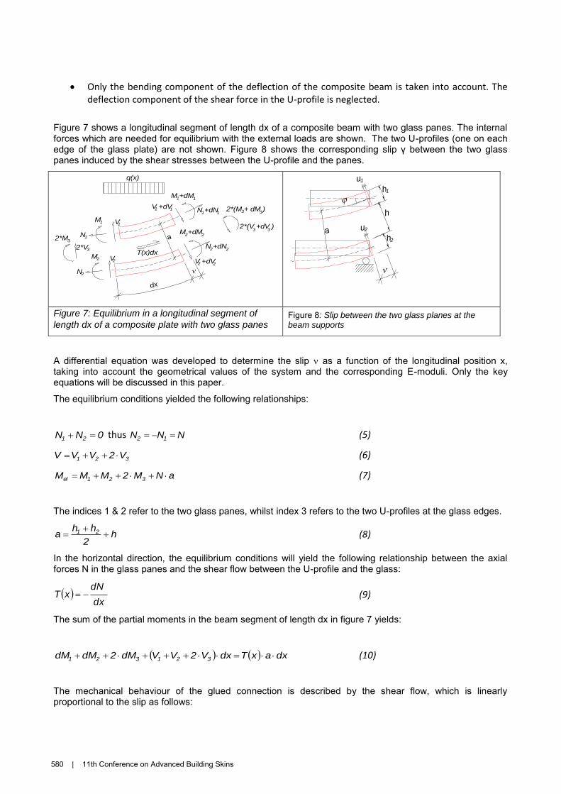
Figure 7 shows a longitudinal segment of length dx of a composite beam with two glass panes. The internalforces which are needed for equilibrium with the external loads are shown. The two U-profiles (one on eachedge of the glass plate) are not shown. Figure 8 shows the corresponding slip γ between the two glasspanes induced by the shear stresses between the U-profile and the panes.
Figure 7: Equilibrium in a longitudinal segment of
length dx of a composite plate with two glass panes Figure 8: Slip between the two glass planes at thebeam supports
A differential equation was developed to determine the slip as a function of the longitudinal position x,taking into account the geometrical values of the system and the corresponding E-moduli. Only the keyequations will be discussed in this paper.
The equilibrium conditions yielded the following relationships:
0NN 21 thus NNN 12 (5)
321 V2VVV (6)
aNM2MMM 321el (7)
The indices 1 & 2 refer to the two glass panes, whilst index 3 refers to the two U-profiles at the glass edges.
h2
hha 21
(8)
In the horizontal direction, the equilibrium conditions will yield the following relationship between the axialforces N in the glass panes and the shear flow between the U-profile and the glass:
dx
dNxT (9)
The sum of the partial moments in the beam segment of length dx in figure 7 yields:
dxaxTdxV2VVdM2dMdM 321321 (10)
The mechanical behaviour of the glued connection is described by the shear flow, which is linearlyproportional to the slip as follows:
V1
V2 V +dV2
2*V3
2
V +dV1 1
M1
N1
M2
N2
T(x)dx
a
M +dM1 1
N +dN1 1
M +dM2 2
N +dN2 2
2*M3
2*(M + dM )3
2*(V +dV )3 3
3
q(x)
dx
a
u1
u2
..
.
h1
h
h2
580 | 11th Conference on Advanced Building Skins

xkxT el (11)
The axial connection force can be obtained from the integration of the shear flow:
1el1 CdxxkCdxxTxN (12)
The slip is equal to the tangent () of the deflection curve, multiplied with the distance between the axes of the two glass panes (a) minus the two deflections induced by the axial connection force N:
xuxuaxx 21 with 0xu 2,1 (13)
The following general form of the differential equation was obtained by integrating equation 13 twice and substituting the relationships above in equations 11 – 13:
1
332211332211
2
2211
el'' Cdxxq
IEIEIE
a
IE2IEIE
a
AE
1
AE
1xkx
(14)
The solution of equation 14 yields the following solution for the slip:
L
xsin
IE2IEIE
a
AE
1
AE
1k
L
qL
IE2IEIE
a
x
332211
2
2211
el2
2
0
332211
(15)
The axial connection force N(x) as well as the curvature (x) of the beam can be readily calculated from the slip determined in equation 15 above. Thus the total moment Mel(x) and the beam deflection w(x) can also be determined.
The effective flexural stiffness (EIeff) is the relationship between the moment (Mel) and the curvature ():
x
xMEI el
eff
(16)
The effective flexural stiffness (EIeff) is also a function of the geometry, sizes of the glass panes and the U-profile, as well as the stiffness of the shear connection. Equation 16 can be simplified in analogy to the so-called „gamma-method” as a function of the bending stiffnesses EI1,2,3 of the component parts, a connection factor () as well as the «Steiner-portion» (S):
SIE2IEIEEI 332211eff (17)
11th Conference on Advanced Building Skins | 581
The «Steiner-portion» (S) is determined solely from the properties of the glass panes as follows. The U-profile is neglected in this calculation.
For E1 = E2: 21
212
2,1
hh
hhbaES
(18)
The factor of the strengthened system:
212
2,122
el12
el
212
el
hhbEhLkhLk
)hh(Lk
(19)
The equation for can be further simplified as follows:
xk
hhEhh
hhx
el
212
2,1
21
21
with
b
Lx
2
(20)
For a symmetrical glass construction (h1 = h2):
1
el
2,12
2,1
xk2
hE1x
(21)
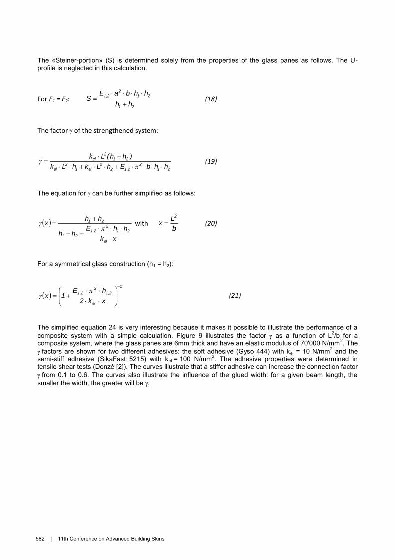
The simplified equation 24 is very interesting because it makes it possible to illustrate the performance of acomposite system with a simple calculation. Figure 9 illustrates the factor as a function of L2/b for a composite system, where the glass panes are 6mm thick and have an elastic modulus of 70'000 N/mm2. The factors are shown for two different adhesives: the soft adhesive (Gyso 444) with kel = 10 N/mm2 and the semi-stiff adhesive (SikaFast 5215) with kel = 100 N/mm2. The adhesive properties were determined in tensile shear tests (Donzé [2]). The curves illustrate that a stiffer adhesive can increase the connection factorfrom 0.1 to 0.6. The curves also illustrate the influence of the glued width: for a given beam length, thesmaller the width, the greater will be
582 | 11th Conference on Advanced Building Skins
Figure 9: Factor γ as a function of L2/b and kel, for h1 = h2 = 6 mm and E1,2 = 70'000 N/mm
2
3. Experimental work
3.1 Four point bending tests
The aim of the experimental part of the project was to determine the bending stiffness (EIg) of the insulated glass before, and after it has been strengthened with the U-profiles. The results would make possible to estimate the statical performance of the glass element as a function of the adhesive used. The test results could thus be compared to the theoretical results, in order to verify the accuracy of the calculation modelling.
In a first phase, the glass elements were tested without the U-profile and the bending stiffness (EIg) and the slip () was measured. In the next phase, the glass elements were strengthened with the U-profiles and then tested till failure to yield data on the performance of the composite system, in particular the bending stiffness (EIeff), the maximum load (Fmax), the slip () and the deflection at midspan (wmax).
3.2 Description of the test specimens
The test specimens were all insulated glass elements of the Swiss company «Verres industriels SA à Moutier». The elements comprised two glass panes and were 28mm thick, 700mm wide and 2000mm long. The official name of the company for the product was: Glass (1): 6-16EA (Argon)-6Low-E, ttotal = 28 mm. The E-modulus was 70’000 N/mm
2.
Two different adhesives were used to glue the U-profile to the glass elements:
MS-polymers: Gyso 444, Kel = 100 N/mm two-component-acryl-adhesive: SikaFast 5215, Kel = 900 N/mm
The U-profiles used in the tests were made of glass fibres and polyester (GFP). Because there was no other information available, tensile tests were carried out to determine the following values (Donzé [2]):
Tensile strength (average value): ft,90 = 800 N/mm2 (Number of test specimens n = 5) Modulus of elasticity (average value): Et,90,mean = 30'500 N/mm2 (n = 5)
The adhesive was applied with a thickness of 2mm. The width of the glued surface was 15 mm; the length of the element was 2000 mm.
0
0.1
0.2
0.3
0.4
0.5
0.6
0 5000 10000 15000 20000 25000
Fact
or [
-]
L2/b
Factor as a function of L2/b for two different adhesive stiffesses (kel)
kel = 10 N/mm2(Gyso 444)
kel = 100 N/mm2(SikaFast 5215)
L = Spanb = Width
11th Conference on Advanced Building Skins | 583
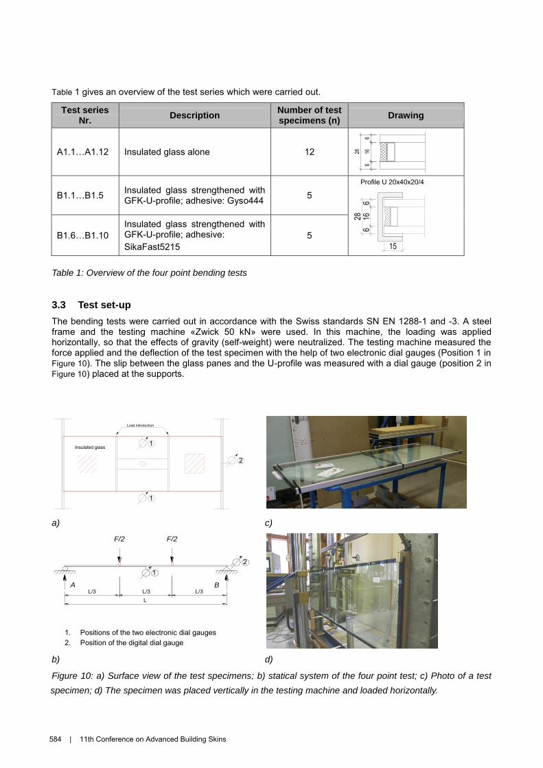
Table 1 gives an overview of the test series which were carried out.
Test series Nr.
Description Number of test specimens (n)
Drawing
A1.1…A1.12 Insulated glass alone 12
B1.1…B1.5Insulated glass strengthened withGFK-U-profile; adhesive: Gyso444 5
B1.6…B1.10
Insulated glass strengthened withGFK-U-profile; adhesive:SikaFast5215
5
Table 1: Overview of the four point bending tests
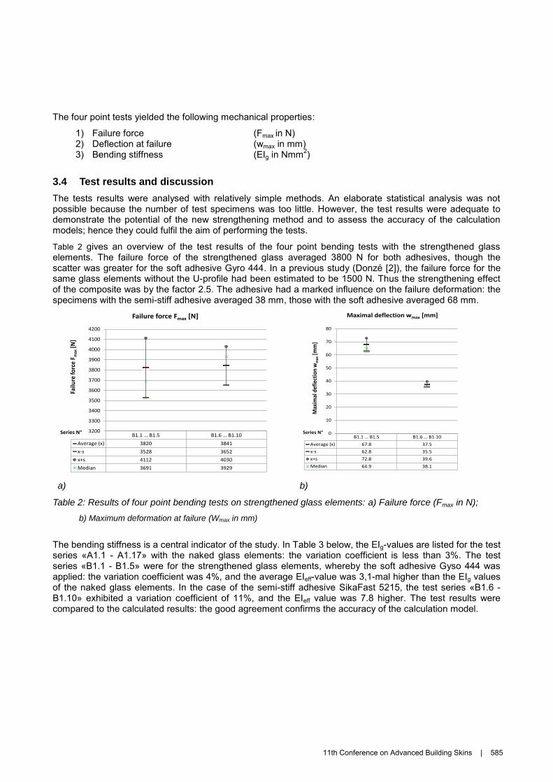
3.3 Test set-up
The bending tests were carried out in accordance with the Swiss standards SN EN 1288-1 and -3. A steelframe and the testing machine «Zwick 50 kN» were used. In this machine, the loading was appliedhorizontally, so that the effects of gravity (self-weight) were neutralized. The testing machine measured theforce applied and the deflection of the test specimen with the help of two electronic dial gauges (Position 1 inFigure 10). The slip between the glass panes and the U-profile was measured with a dial gauge (position 2 inFigure 10) placed at the supports.
a) c)
1. Positions of the two electronic dial gauges2. Position of the digital dial gauge
b) d)
Figure 10: a) Surface view of the test specimens; b) statical system of the four point test; c) Photo of a test
Profile U 20x40x20/4
1
Load introduction
2
1Insulated glass
A B
LL/3 L/3 L/3
F/2 F/2
12
584 | 11th Conference on Advanced Building Skins
specimen; d) The specimen was placed vertically in the testing machine and loaded horizontally.
The four point tests yielded the following mechanical properties:
1) Failure force (Fmax in N) 2) Deflection at failure (wmax in mm) 3) Bending stiffness (EIg in Nmm2)
3.4 Test results and discussion
The tests results were analysed with relatively simple methods. An elaborate statistical analysis was not possible because the number of test specimens was too little. However, the test results were adequate to demonstrate the potential of the new strengthening method and to assess the accuracy of the calculation models; hence they could fulfil the aim of performing the tests.
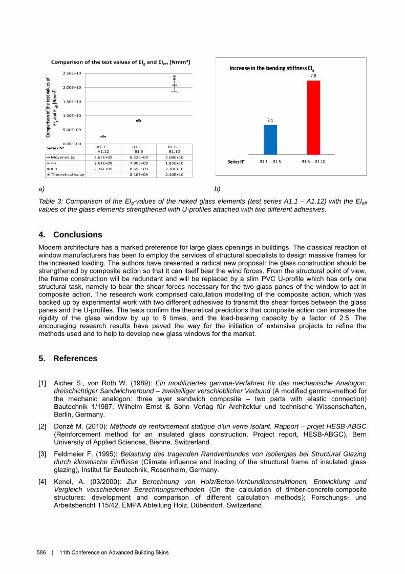
Table 2 gives an overview of the test results of the four point bending tests with the strengthened glass elements. The failure force of the strengthened glass averaged 3800 N for both adhesives, though the scatter was greater for the soft adhesive Gyro 444. In a previous study (Donzé [2]), the failure force for the same glass elements without the U-profile had been estimated to be 1500 N. Thus the strengthening effect of the composite was by the factor 2.5. The adhesive had a marked influence on the failure deformation: the specimens with the semi-stiff adhesive averaged 38 mm, those with the soft adhesive averaged 68 mm.
a) b)
Table 2: Results of four point bending tests on strengthened glass elements: a) Failure force (Fmax in N);
b) Maximum deformation at failure (Wmax in mm)
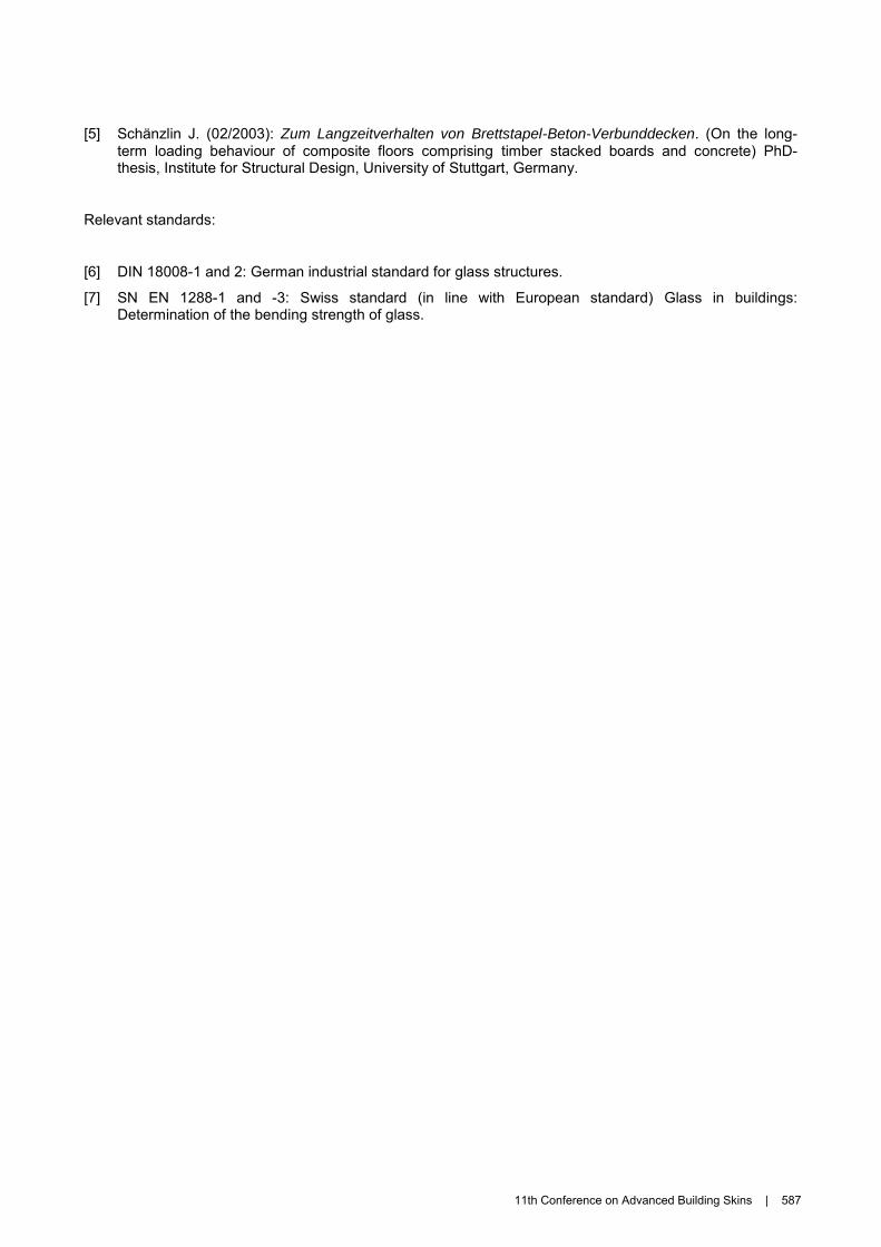
The bending stiffness is a central indicator of the study. In Table 3 below, the EIg-values are listed for the test series «A1.1 - A1.17» with the naked glass elements: the variation coefficient is less than 3%. The test series «B1.1 - B1.5» were for the strengthened glass elements, whereby the soft adhesive Gyso 444 was applied: the variation coefficient was 4%, and the average EIeff-value was 3,1-mal higher than the EIg values of the naked glass elements. In the case of the semi-stiff adhesive SikaFast 5215, the test series «B1.6 - B1.10» exhibited a variation coefficient of 11%, and the EIeff value was 7.8 higher. The test results were compared to the calculated results: the good agreement confirms the accuracy of the calculation model.
B1.1 … B1.5 B1.6 … B1.10
Average (x) 3820 3841
x-s 3528 3652
x+s 4112 4030
Median 3691 3929
3200
3300
3400
3500
3600
3700
3800
3900
4000
4100
4200
Failu
re fo
rce
F max
[N]
Failure force Fmax [N]
Series N°B1.1 … B1.5 B1.6 … B1.10
Average (x) 67.8 37.5
x-s 62.8 35.5
x+s 72.8 39.6
Median 64.9 38.1
0
10
20
30
40
50
60
70
80
Max
imal
def
lect
ion
wm
ax[m
m]
Maximal deflection wmax [mm]
Series N°
11th Conference on Advanced Building Skins | 585
a) b)
Table 3: Comparison of the EIg-values of the naked glass elements (test series A1.1 – A1.12) with the EIeff
values of the glass elements strengthened with U-profiles attached with two different adhesives.
4. Conclusions
Modern architecture has a marked preference for large glass openings in buildings. The classical reaction ofwindow manufacturers has been to employ the services of structural specialists to design massive frames forthe increased loading. The authors have presented a radical new proposal: the glass construction should bestrengthened by composite action so that it can itself bear the wind forces. From the structural point of view,the frame construction will be redundant and will be replaced by a slim PVC U-profile which has only onestructural task, namely to bear the shear forces necessary for the two glass panes of the window to act incomposite action. The research work comprised calculation modelling of the composite action, which wasbacked up by experimental work with two different adhesives to transmit the shear forces between the glasspanes and the U-profiles. The tests confirm the theoretical predictions that composite action can increase therigidity of the glass window by up to 8 times, and the load-bearing capacity by a factor of 2.5. Theencouraging research results have paved the way for the initiation of extensive projects to refine themethods used and to help to develop new glass windows for the market.
5. References
[1] Aicher S., von Roth W. (1989): Ein modifiziertes gamma-Verfahren für das mechanische Analogon: dreischichtiger Sandwichverbund – zweiteiliger verschieblicher Verbund (A modified gamma-method forthe mechanic analogon: three layer sandwich composite – two parts with elastic connection)Bautechnik 1/1987, Wilhelm Ernst & Sohn Verlag für Architektur und technische Wissenschaften,Berlin, Germany.
[2] Donzé M. (2010): Méthode de renforcement statique d’un verre isolant. Rapport – projet HESB-ABGC(Reinforcement method for an insulated glass construction. Project report, HESB-ABGC), BernUniversity of Applied Sciences, Bienne, Switzerland.
[3] Feldmeier F. (1995): Belastung des tragenden Randverbundes von Isolierglas bei Structural Glazing durch klimatische Einflüsse (Climate influence and loading of the structural frame of insulated glassglazing), Institut für Bautechnik, Rosenheim, Germany.
[4] Kenel, A. (03/2000): Zur Berechnung von Holz/Beton-Verbundkonstruktionen, Entwicklung und Vergleich verschiedener Berechnungsmethoden (On the calculation of timber-concrete-compositestructures: development and comparison of different calculation methods); Forschungs- undArbeitsbericht 115/42, EMPA Abteilung Holz, Dübendorf, Switzerland.
A1.1 … A1.12
B1.1 … B1.5
B1.6 … B1.10
Moyenne (x) 2.67E+09 8.22E+09 2.08E+10
x-s 2.61E+09 7.90E+09 1.85E+10
x+s 2.74E+09 8.55E+09 2.30E+10
Theoretical value 8.16E+09 2.40E+10
0.00E+00
5.00E+09
1.00E+10
1.50E+10
2.00E+10
2.50E+10
Com
paris
on o
f the
test
val
ues o
fEI
gan
d EI
eff[N
mm
2 ]
Comparison of the test values of EIg and EIeff [Nmm2]
Series N°
586 | 11th Conference on Advanced Building Skins
[5] Schänzlin J. (02/2003): Zum Langzeitverhalten von Brettstapel-Beton-Verbunddecken. (On the long-term loading behaviour of composite floors comprising timber stacked boards and concrete) PhD-thesis, Institute for Structural Design, University of Stuttgart, Germany.
Relevant standards:
[6] DIN 18008-1 and 2: German industrial standard for glass structures.
[7] SN EN 1288-1 and -3: Swiss standard (in line with European standard) Glass in buildings: Determination of the bending strength of glass.
11th Conference on Advanced Building Skins | 587