Embed Size (px)
Citation preview
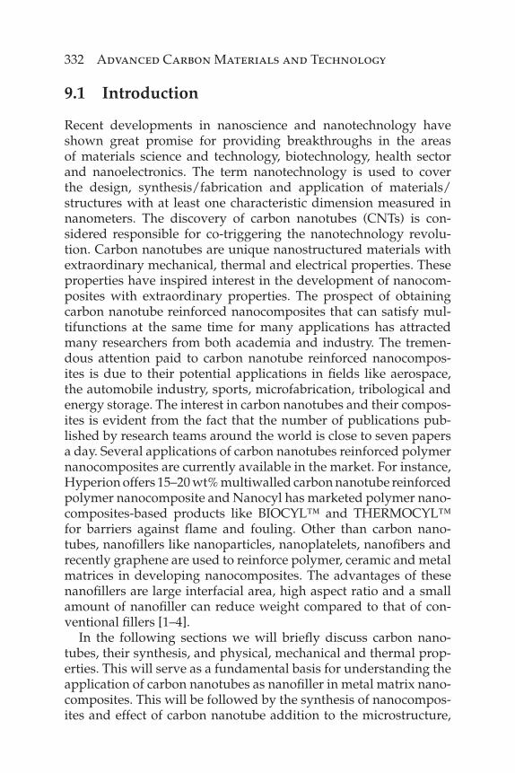
331
Ashutosh Tiwari and S.K. Shukla (eds.) Advanced Carbon Materials and Technology, (331–376) 2014 © Scrivener Publishing LLC
9
Metal Matrix Nanocomposites Reinforced with Carbon Nanotubes
Praveennath G. Koppad1,2, Vikas Kumar Singh3,*, C.S. Ramesh1, Ravikiran G. Koppad4 and K.T. Kashyap1
1Advanced Composites Research Center, Department of Mechanical Engineering, PES Institute of Technology, Bangalore, India
2Research and Development, Rapsri Engineering Products Company Ltd., Bangalore, India
3Department of Industrial Production Engineering, GITAM Institute of Technology, GITAM University, Visakhapatnam, India
4Department of Electrical and Electronics Engineering, BV Bhommaraddi College of Engineering and Technology, Hubli, India
AbstractCarbon nanotubes are the unique nanostructures of carbon having high surface area per unit weight, low density, superior elastic modulus and tensile strength as well as remarkable thermal and electrical properties. On the other hand, considerable research effort has been directed towards the development of metal matrix nanocomposites using a wide range of matrix materials including aluminium, copper, magnesium, nickel and titanium reinforced with nanofi ller materials like nanoplatelets, nanopar-ticles, nanofi bers and carbon nanotubes. In this chapter, the recent research and development on the use of carbon nanotubes as reinforcement and their effect on mechanical, thermal and tribological properties of metal matrix nanocomposites are presented. The challenges related to the syn-thesis of nanocomposites using various processing techniques, dispersion of carbon nanotubes, interfacial bonding and strengthening mechanisms are discussed.
Keywords: Carbon nanotubes, metal matrix nanocomposites, mechanical properties, thermal properties
*Corresponding author: [email protected]
332 Advanced Carbon Materials and Technology
9.1 Introduction
Recent developments in nanoscience and nanotechnology have shown great promise for providing breakthroughs in the areas of materials science and technology, biotechnology, health sector and nanoelectronics. The term nanotechnology is used to cover the design, synthesis/fabrication and application of materials/structures with at least one characteristic dimension measured in nanometers. The discovery of carbon nanotubes (CNTs) is con-sidered responsible for co-triggering the nanotechnology revolu-tion. Carbon nanotubes are unique nanostructured materials with extraordinary mechanical, thermal and electrical properties. These properties have inspired interest in the development of nanocom-posites with extraordinary properties. The prospect of obtaining carbon nanotube reinforced nanocomposites that can satisfy mul-tifunctions at the same time for many applications has attracted many researchers from both academia and industry. The tremen-dous attention paid to carbon nanotube reinforced nanocompos-ites is due to their potential applications in fi elds like aerospace, the automobile industry, sports, microfabrication, tribological and energy storage. The interest in carbon nanotubes and their compos-ites is evident from the fact that the number of publications pub-lished by research teams around the world is close to seven papers a day. Several applications of carbon nanotubes reinforced polymer nanocomposites are currently available in the market. For instance, Hyperion offers 15–20 wt% multiwalled carbon nanotube reinforced polymer nanocomposite and Nanocyl has marketed polymer nano-composites-based products like BIOCYL™ and THERMOCYL™ for barriers against fl ame and fouling. Other than carbon nano-tubes, nanofi llers like nanoparticles, nanoplatelets, nanofi bers and recently graphene are used to reinforce polymer, ceramic and metal matrices in developing nanocomposites. The advantages of these nanofi llers are large interfacial area, high aspect ratio and a small amount of nanofi ller can reduce weight compared to that of con-ventional fi llers [1–4].
In the following sections we will briefl y discuss carbon nano-tubes, their synthesis, and physical, mechanical and thermal prop-erties. This will serve as a fundamental basis for understanding the application of carbon nanotubes as nanofi ller in metal matrix nano-composites. This will be followed by the synthesis of nanocompos-ites and effect of carbon nanotube addition to the microstructure,
Metal Matrix Nanocomposites 333
mechanical, thermal and tribological properties of nanocomposites. Finally, the challenges faced and need to overcome them for suc-cessful realization of commercial applications of carbon nanotube reinforced metal matrix nanocomposites is described. Those intend-ing to get deep into the subject can refer to references [3] and [9].
9.2 Carbon Nanotubes
Carbon is the most unique element and exists in two well-known crystalline forms: diamond and graphite. The arrangement of elec-trons around the nucleus of the atom makes these allotropic forms either extremely hard or very soft. The new additions to the carbon allotropes family are fullerenes, the closed-cage carbon molecules, for example C60 and nanotubules of graphite, popularly known as carbon nanotubes. Discovered by Kroto et al. [5] in 1985 at Rice University, the fullerenes are closed-shell confi guration of sp2 hybridized carbon cluster. The famous C60, also known as “Bucky ball,” is the most thoroughly studied member among the fuller-enes and consists of 12 pentagonal and 20 hexagonal rings fused together forming a cage-like structure. This was followed by the discovery of carbon nanotubes which opened up an era in nano-science and nanotechnology. Carbon nanotubes were discovered in 1991 by Japanese scientist Sumio Iijima during the examination of carbon soot produced by arc evaporation of graphite in helium atmosphere [6]. The nanotubes observed in high-resolution trans-mission electron microscopy (HRTEM) were multi-walled and had a diameter in the range of 4 to 30 nm and length up to 1 μm. Carbon nanotubes are the graphene sheets of hexagonal carbon rings rolled into long cylinders with both ends capped by fullerene-like structures. Two years later, Iijima et al. [7] and Bethune et al. [8] independently reported the synthesis of nanotubes having single walls. Single-walled carbon nanotubes (SWCNTs) are composed of single graphene cylinder, whereas multiwalled carbon nanotubes (MWCNTs) consist of many nested cylinders with an interlayer spacing of 0.34 nm. The carbon nanotubes can have a variety of structures, namely armchair, zig-zag and chiral, by rolling the gra-phene sheets with varying degrees of twist along its length.
The early carbon nanotubes were synthesized by electric-arc dis-charge method, in which an arc was triggered between graphite electrodes in helium atmosphere. Since then a number of ways of
334 Advanced Carbon Materials and Technology
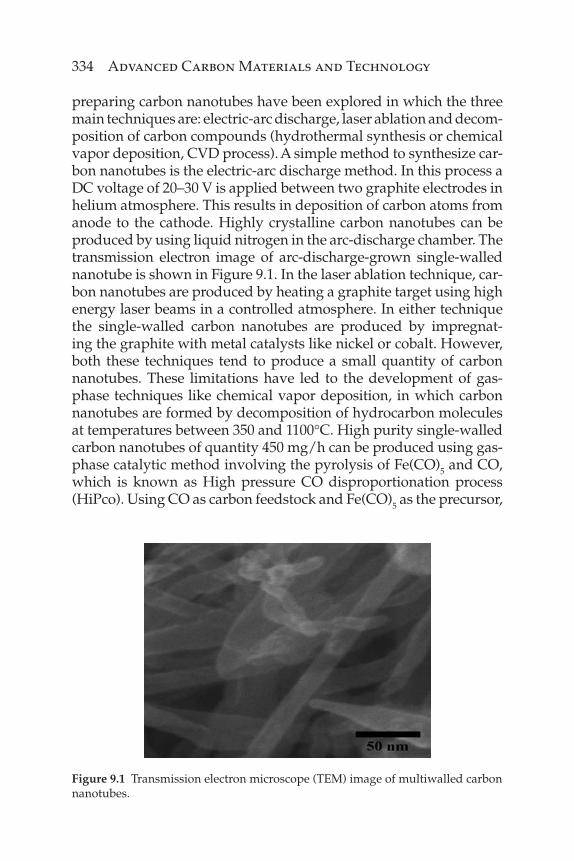
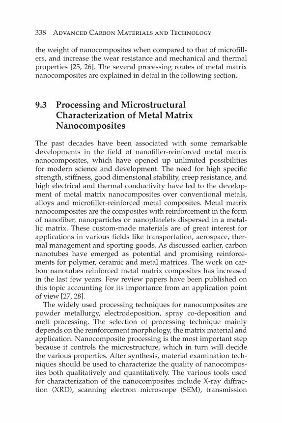
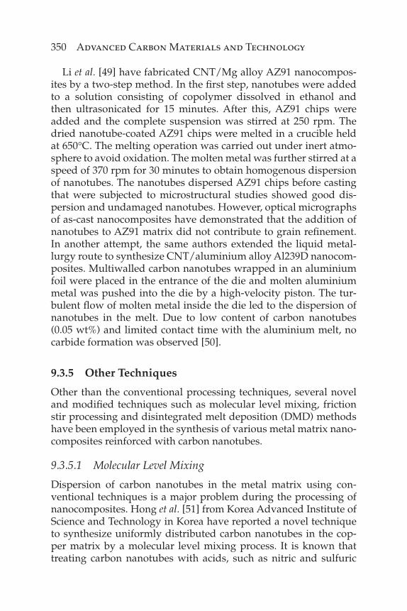
preparing carbon nanotubes have been explored in which the three main techniques are: electric-arc discharge, laser ablation and decom-position of carbon compounds (hydrothermal synthesis or chemical vapor deposition, CVD process). A simple method to synthesize car-bon nanotubes is the electric-arc discharge method. In this process a DC voltage of 20–30 V is applied between two graphite electrodes in helium atmosphere. This results in deposition of carbon atoms from anode to the cathode. Highly crystalline carbon nanotubes can be produced by using liquid nitrogen in the arc-discharge chamber. The transmission electron image of arc-discharge-grown single-walled nanotube is shown in Figure 9.1. In the laser ablation technique, car-bon nanotubes are produced by heating a graphite target using high energy laser beams in a controlled atmosphere. In either technique the single-walled carbon nanotubes are produced by impregnat-ing the graphite with metal catalysts like nickel or cobalt. However, both these techniques tend to produce a small quantity of carbon nanotubes. These limitations have led to the development of gas-phase techniques like chemical vapor deposition, in which carbon nanotubes are formed by decomposition of hydrocarbon molecules at temperatures between 350 and 1100°C. High purity single-walled carbon nanotubes of quantity 450 mg/h can be produced using gas-phase catalytic method involving the pyrolysis of Fe(CO)5 and CO, which is known as High pressure CO disproportionation process (HiPco). Using CO as carbon feedstock and Fe(CO)5 as the precursor,
Figure 9.1 Transmission electron microscope (TEM) image of multiwalled carbon nanotubes.
Metal Matrix Nanocomposites 335
the single-walled carbon nanotubes are produced under continu-ous fl ow of CO over the catalytic clusters of iron. The production of nanotubes by the HiPco approach can be 10 g/day, but the yield can still be improved by recirculation of CO using a compressor rather being released into the atmosphere. The unique aspects of the CVD process are good alignment, and the achievement of precise control over the diameter and length of carbon nanotubes. Depending on the heating source, CVD can be classifi ed into plasma-enhanced, thermal- and laser-assisted CVD. Out of these, the laser-assisted CVD technique has higher deposition rates than conventional CVD and offers the possibility to scale-up the nanotube production [9].
Within the plane, three out of four electrons in carbon atom form three σ bonds, a sp2 hybrid bond. Carbon nanotube with σ bond structuring is considered as the stiffest and strongest fi ber to date. A large number of theoretical and experimental studies have been conducted on the estimation of mechanical properties of carbon nanotubes. Studies have confi rmed that the axial elastic modulus of carbon nanotube is almost equal to 1.04 Tpa, which is the same as that of in-plane elastic modulus of graphite [10]. A theoretical study on the prediction of Young’s modulus of carbon nanotubes using a Keating Hamiltonian with parameters determined from fi rst prin-ciples was conducted by Overney et al. [11], which gave an estima-tion of between 1.5 to 5.0 TPa. Elastic and shear modulus prediction of carbon nanotubes by Lu et al. [12] using a molecular dynamics approach showed a value of 1.0 TPa and 0.5 Tpa, respectively. The nanotube diameter and the number of walls were found to have a negligible effect on the value of elastic modulus. Kashyap et al. [13] have calculated the Young’s modulus by assessing the bending of multiwalled carbon nanotubes at the subgrain boundaries in CNT/Al nanocomposites. The value obtained from this analysis was about 0.9 TPa. The tensile strength measurements of both single-walled and multiwalled carbon nanotubes carried out by Yu et al. [14, 15] was found to be in the range of 13–52 GPa and 11–63 Gpa, respectively. The tensile strength and fracture studies on 19 multi-walled carbon nanotubes were carried out by using atomic force microscope tip for applying load. The breaking strength obtained was in the range of 11 to 63 GPa and strain at break reached up to 12%. In the case of single-walled carbon nanotubes, about 15 carbon nanotube ropes were tensile loaded in a nanostressing stage oper-ated inside a scanning electron microscope. The average strength values were in the range of 13 to 52 GPa.
336 Advanced Carbon Materials and Technology
Both the allotropes of carbon, namely, graphite and diamond, do exhibit excellent heat capacity and thermal conductivity. The theoretically predicted and measured thermal conductivity values of individual carbon nanotubes are higher than that of graphite. The thermal conductance in nanotubes is due to both phonons and electrons. However, it is still unclear how much of the thermal con-ductance is due to phonons and due to electrons. But it is presumed that most of the heat is carried by phonons. Using combined results of equilibrium and nonequilibrium molecular dynamics, Berber et al. [16] showed that an isolated nanotube (10,10) possesses a ther-mal conductivity of 6600 W/mK at room temperature. The meso-scopic thermal transport measurements of a single multiwalled carbon nanotube showed a thermal conductivity of 3000 W/mK at room temperature and the phonon mean free path was found to be 500 nm [17]. However, the average thermal conductivity of multi-walled carbon nanotube fi lms with a fi lm thickness of 10 to 50 μm was found to be 15 W/mK at room temperature. The low thermal conductivity value resulted from intertube coupling and defects in the nanotubes causing scattering of phonons [18].
Wetting and capillarity of carbon nanotubes studied by Dujardin et al. [19] revealed that the elements with a surface tension below 100 mN/m can wet the nanotubes. The determining factor for wetting was surface tension, and for nanotubes the cutoff point is between 100 and 200 mN/m. The inner cavity of closed nanotubes could easily be fi lled up with lead compound in an oxidizing environ-ment, whereas the nanotubes with opened tips exposed to molten metal in an inert atmosphere were not drawn in by capillarity. This work showed that the materials with low surface tension could be drawn inside nanotubes by capillary forces. If the pure metals are to be fi lled in nanotubes, then depending on the diameter of tube and contact angle, an outside pressure must be applied.
Owing to its excellent properties, carbon nanotubes are used in various applications like nanocomposites, chemical sensors, bio-sensors, nanoelectronics, electrochemical devices, hydrogen stor-age and fi eld emission devices. For example, the addition of carbon nanotubes to polymers not only reinforces but introduces new elec-tronic properties based on the electronic interaction between the two phases. This enables the polymer nanocomposites to be used as a material for applications in photovoltaic devices and light emit-ting diodes. Due to its high aspect ratio and physical properties, carbon nanotubes are suitable for fi eld emitter applications, which
Metal Matrix Nanocomposites 337
was successfully demonstrated by Samsung SDI’s fabrication of a prototype 4.5-inch color fi eld emission display panel made using single-walled carbon nanotubes. Carbon nanotubes are being con-sidered to replace semiconducting metal oxides for chemical sensor applications. The electrical conductance of semiconducting carbon nanotubes is highly sensitive to the change in chemical composition of the surroundings. This response is attributed to the charge trans-fer between the p-type semiconducting nanotube and molecules from the gases adsorbed onto the nanotube surface, when electri-cally charged nanotubes tend to act as actuators and can be used as nano-tweezers for grabbing or releasing the nanoscale structures. Carbon nanotubes are being projected as a tip for scanning probe microscopes because of the promise of ultrahigh lateral resolution due to their smaller diameter (~2 nm). However, technical issues related to growth, morphology and orientation of nanotubes on a wafer must be overcome to realize the commercial applications in industries. The carbon nanotubes are found to be suitable candi-dates for drug delivery systems given that a wide range of drugs can be adsorbed on their walls. The functionalized carbon nano-tubes with more than one therapeutic agent with recognition capac-ity and specifi c targeting have created great interest for use in the treatment of cancer [20–24].
Most of the work on nanocomposites has been focused on rein-forcement of polymers by carbon nanotubes due to their low pro-cessing temperatures and small stresses involved compared to that of metal and ceramic matrices. The incorporation of carbon nanotubes to ceramic matrix has been aimed at enhancing the frac-ture toughness and improving the thermal shock resistance. The increase in fracture toughness was observed in ceramic matrices like SiO2, Al2O3 and BaTiO3. The addition of carbon nanotubes to Al2O3 matrix resulted in high wear resistance and low coeffi cient of friction by serving as lubricating medium. Research on metal matrix nanocomposites made from carbon nanotubes is receiving much attention and is being projected for applications in structural and electronic packaging. During the last decade a lot of work has been carried out on the synthesis and characterization of metal matrix nanocomposites reinforced with carbon nanotubes. Aluminium is the most sought-after matrix material due to its low density and good mechanical properties, followed by other metals like copper, nickel, magnesium and titanium. The addition of a small amount of carbon nanotubes to these metallic matrices can signifi cantly reduce
338 Advanced Carbon Materials and Technology
the weight of nanocomposites when compared to that of microfi ll-ers, and increase the wear resistance and mechanical and thermal properties [25, 26]. The several processing routes of metal matrix nanocomposites are explained in detail in the following section.
9.3 Processing and Microstructural Characterization of Metal Matrix Nanocomposites
The past decades have been associated with some remarkable developments in the fi eld of nanofi ller-reinforced metal matrix nanocomposites, which have opened up unlimited possibilities for modern science and development. The need for high specifi c strength, stiffness, good dimensional stability, creep resistance, and high electrical and thermal conductivity have led to the develop-ment of metal matrix nanocomposites over conventional metals, alloys and microfi ller-reinforced metal composites. Metal matrix nanocomposites are the composites with reinforcement in the form of nanofi ber, nanoparticles or nanoplatelets dispersed in a metal-lic matrix. These custom-made materials are of great interest for applications in various fi elds like transportation, aerospace, ther-mal management and sporting goods. As discussed earlier, carbon nanotubes have emerged as potential and promising reinforce-ments for polymer, ceramic and metal matrices. The work on car-bon nanotubes reinforced metal matrix composites has increased in the last few years. Few review papers have been published on this topic accounting for its importance from an application point of view [27, 28].
The widely used processing techniques for nanocomposites are powder metallurgy, electrodeposition, spray co-deposition and melt processing. The selection of processing technique mainly depends on the reinforcement morphology, the matrix material and application. Nanocomposite processing is the most important step because it controls the microstructure, which in turn will decide the various properties. After synthesis, material examination tech-niques should be used to characterize the quality of nanocompos-ites both qualitatively and quantitatively. The various tools used for characterization of the nanocomposites include X-ray diffrac-tion (XRD), scanning electron microscope (SEM), transmission
Metal Matrix Nanocomposites 339
electron microscope (TEM), energy dispersed spectroscopy (EDS) and Raman spectroscopy. The SEM and TEM can provide the mor-phological features of nanocomposites such as carbon nanotubes distribution in the metal matrices, if any chemical reaction prod-ucts formed at the interface between carbon nanotubes and metal matrix, and can image the defects like stacking fault or dislocations generated due to the addition of carbon nanotubes. X-ray diffrac-tion is used mainly to study the phases present after the process-ing of nanocomposites, including determination of grain size of the matrix, or in computing the dislocation density. In this section the focus is on the processing and characterization techniques involved in carbon nanotubes reinforced metal matrix nanocomposites.
9.3.1 Powder Metallurgy
Powder metallurgy is a material processing technology in which material is taken in powder form, compacted into the desired shape and sintered to cause bonding between the particles. The main advantage of this technology over others is that it involves very little waste of material and about 98% of the starting material powders are converted into product. For the nanocomposite production the matrix and reinforcement powders are blended ultrasonically or using a ball mill to produce homogeneous distribution. The blending stage is followed by either cold pressing or hot pressing. The cold-pressed nanocomposite compact is subjected to sintering to provide bonding of solid particles by application of temperature. Further, the sintered nanocomposite compacts can be subjected to second-ary processing techniques such as extrusion, rolling and forging. Most of the studies on carbon nanotubes reinforced aluminium, cop-per, magnesium and titanium metal matrices nanocomposites have been prepared using the powder metallurgy technique. Kuzumaki et al. [29] were the fi rst to report the synthesis of carbon nanotubes reinforced aluminum composites by hot press and hot extrusion methods. The carbon nanotubes synthesized by DC arc-discharge were stirred with aluminum powders in ethanol at 300 rpm for 30 minutes. The composite powders were loaded in an aluminum can and hot pressed in a steel die with a pressure of 100 MPa. The hot-pressed samples were hot extruded at a temperature of 500°C into a rod at a speed of 10 mm/min. Microstructural studies revealed the coalescence of carbon nanotubes in the aluminum matrix. The obser-vation at the interface between carbon nanotube and aluminum
340 Advanced Carbon Materials and Technology
matrix showed no chemical reaction. This was followed by synthesis of CNT/Cu composite by Chen et al. [30]. In this study the authors prepared CNT/Cu copper composite by ball milling, compaction of ball-milled powder at a pressure of 600 MPa at 100°C for 10 minutes followed by sintering at 800°C for 2 hours. The CNT/Cu composite with 16 vol% CNTs showed high porosity which was due to agglom-eration of CNTs due to high volume fraction. George et al. [31] used single-walled and multiwalled carbon nanotubes synthesized by arc-discharge technique to reinforce commercial purity aluminum. Some of the carbon nanotubes were coated with K2ZrF6 to improve the bonding between carbon nanotubes and aluminium matrix. The powders were ball milled at 200 rpm for 5 minutes. The milled com-posite powder was compacted, sintered at 580°C and hot extruded at 560°C. X-ray diffraction of nanocomposites showed no aluminium carbide formation. The TEM images of nanocomposites revealed the pinning of subgrain boundaries by carbon nanotubes. It was pro-posed that due to the coeffi cient of thermal expansion mismatch between carbon nanotubes (~10–6 K-1) and aluminium (23.6×10⁻⁶ K-1), dislocations were generated around the carbon nanotubes. However, it is interesting to note that no free dislocations were observed in the subgrains due to the possibility of dislocations being captured by low angle tilt boundaries at the subgrains.
It is very important for processing techniques to achieve uniform dispersion of carbon nanotubes inside the metal matrices to real-ize their outstanding mechanical and thermal properties. In order to address the dispersion of carbon nanotubes in the metal matri-ces, Esawi et al. [32] chose mechanical alloying to achieve uniform dispersion of nanotubes in the aluminium powders. About 2 wt% of multiwalled carbon nanotubes and aluminum powder of 75 μm were milled in planetary ball mill up to 48 hours with a ball to pow-der ratio of 10:1. The morphology of ball-milled powders were ana-lyzed using fi eld emission scanning electron microscope (FESEM). It was observed that in the initial stage aluminum particles were fl attened under the impact of balls and then started welding to form large particles. After 24 hours of milling the particles reached a size of 3 mm with a very smooth surface. The carbon nanotubes were found to be intact even after 48 hours of milling and were individu-ally embedded inside the aluminum matrix. No detailed investiga-tion was reported on the mechanical alloying with different weight fraction of carbon nanotubes. However, the authors presumed that carbon nanotubes with higher weight fraction in aluminum could
Metal Matrix Nanocomposites 341
make the composite particles less ductile and result in much lower size of particles.
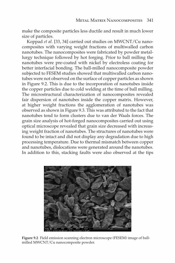
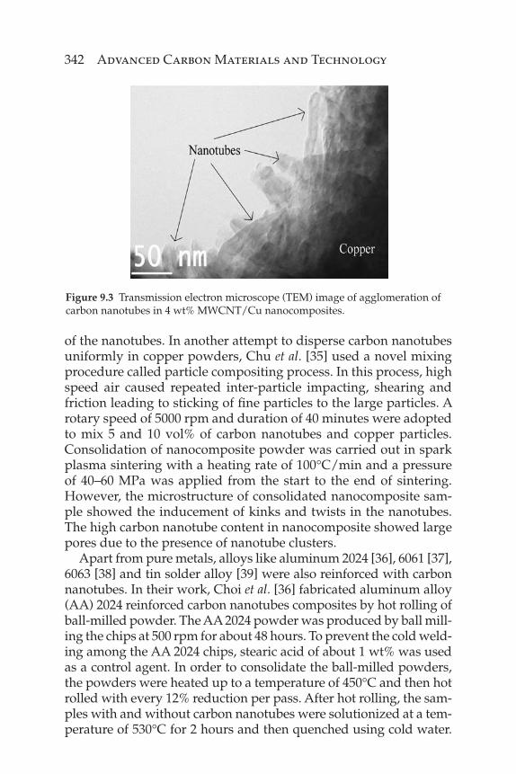
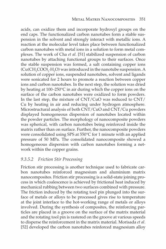
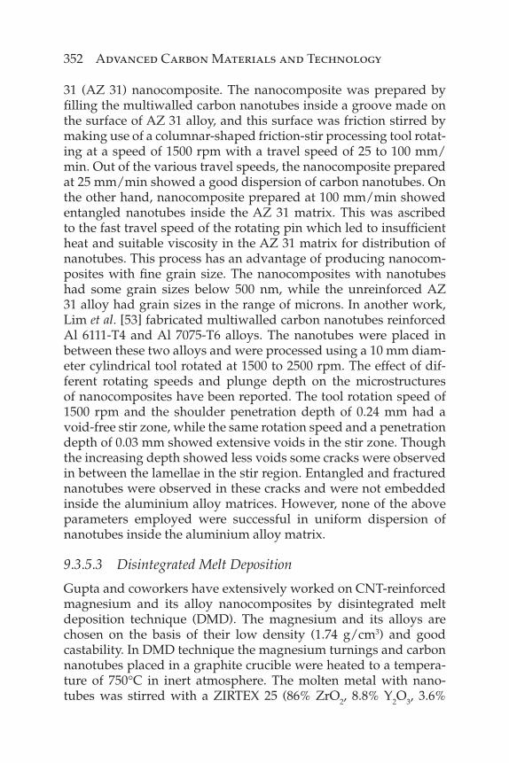
Koppad et al. [33, 34] carried out studies on MWCNT/Cu nano-composites with varying weight fractions of multiwalled carbon nanotubes. The nanocomposites were fabricated by powder metal-lurgy technique followed by hot forging. Prior to ball milling the nanotubes were pre-coated with nickel by electroless coating for better interfacial bonding. The ball-milled nanocomposite powder subjected to FESEM studies showed that multiwalled carbon nano-tubes were not observed on the surface of copper particles as shown in Figure 9.2. This is due to the incorporation of nanotubes inside the copper particles due to cold welding at the time of ball milling. The microstructural characterization of nanocomposites revealed fair dispersion of nanotubes inside the copper matrix. However, at higher weight fractions the agglomeration of nanotubes was observed as shown in Figure 9.3. This was attributed to the fact that nanotubes tend to form clusters due to van der Waals forces. The grain size analysis of hot-forged nanocomposites carried out using optical microscope revealed that grain size decreased with increas-ing weight fraction of nanotubes. The structures of nanotubes were found to be intact and did not display any degradation due to high processing temperature. Due to thermal mismatch between copper and nanotubes, dislocations were generated around the nanotubes. In addition to this, stacking faults were also observed at the tips
Figure 9.2 Field emission scanning electron microscope (FESEM) image of ball-milled MWCNT/Cu nanocomposite powder.
342 Advanced Carbon Materials and Technology
of the nanotubes. In another attempt to disperse carbon nanotubes uniformly in copper powders, Chu et al. [35] used a novel mixing procedure called particle compositing process. In this process, high speed air caused repeated inter-particle impacting, shearing and friction leading to sticking of fi ne particles to the large particles. A rotary speed of 5000 rpm and duration of 40 minutes were adopted to mix 5 and 10 vol% of carbon nanotubes and copper particles. Consolidation of nanocomposite powder was carried out in spark plasma sintering with a heating rate of 100°C/min and a pressure of 40–60 MPa was applied from the start to the end of sintering. However, the microstructure of consolidated nanocomposite sam-ple showed the inducement of kinks and twists in the nanotubes. The high carbon nanotube content in nanocomposite showed large pores due to the presence of nanotube clusters.
Apart from pure metals, alloys like aluminum 2024 [36], 6061 [37], 6063 [38] and tin solder alloy [39] were also reinforced with carbon nanotubes. In their work, Choi et al. [36] fabricated aluminum alloy (AA) 2024 reinforced carbon nanotubes composites by hot rolling of ball-milled powder. The AA 2024 powder was produced by ball mill-ing the chips at 500 rpm for about 48 hours. To prevent the cold weld-ing among the AA 2024 chips, stearic acid of about 1 wt% was used as a control agent. In order to consolidate the ball-milled powders, the powders were heated up to a temperature of 450°C and then hot rolled with every 12% reduction per pass. After hot rolling, the sam-ples with and without carbon nanotubes were solutionized at a tem-perature of 530°C for 2 hours and then quenched using cold water.
Figure 9.3 Transmission electron microscope (TEM) image of agglomeration of carbon nanotubes in 4 wt% MWCNT/Cu nanocomposites.
Metal Matrix Nanocomposites 343
The grain size of ball-milled powders was analyzed using XRD. The grain size of ball-milled AA 2024 powders after 12, 24 and 48 hours were 92, 50 and 90 nm, respectively. Owing to grain growth, the ball milling duration was limited to 24 hours. The hot-rolled sheets of AA 2024 fabricated using 12 and 24 hours of ball-milled powders had average grain sizes of 250 and 100 nm. It was observed that the dislocation density near carbon nanotubes was very high owing to high stress levels, which stimulate the kinetics of precipitation. The precipitates were nucleated at the tips of carbon nanotubes giving rise to an increase in hardness of composite compared to that of AA 2024. Han et al. [39] reported the synthesis of 95.8Sn-3.5Ag-0.7Cu reinforced with nickel-coated multiwalled carbon nanotubes. The starting materials were mixed in a V-type blender for about 10 hours. The nanocomposite powder was subjected to uniaxial compaction and sintering at 175°C for about 2 hours. The compacted sample was extruded at room temperature. The fractographs of nanocomposites showed clustering of nanotubes. The disadvantages of nanotube clusters are that they avoid effective bonding between nanotubes and the tin solder matrix and act as stress concentration sites which promote the formation of cracks.
Most of the methods discussed above have displayed fair disper-sion of carbon nanotubes inside the metal matrices. All the research work employed hot extrusion, hot rolling and hot forging as sec-ondary processing after consolidation of ball-milled nanocompos-ite powders. The secondary processing techniques are employed to improve the density and dispersion of carbon nanotubes and to control the microstructure of nanocomposites. These studies showed that even after hot deformation processing, the integrity of nanotubes was maintained without causing any noticeable damage or degrada-tion of nanotube. However, proper techniques with optimized work-ing parameters are still needed to disperse nanotubes individually in the matrix material. For example, the degree of dispersion of carbon nanotubes in matrix material using ball milling depends on various factors such as type of mill, milling time, milling speed, ball to pow-der ratio, process control agent and the quantity of nanotubes used.
9.3.2 Electroless and Electrodeposition Techniques
Electroless and electrodeposition are the most important techniques for producing composite materials and thin fi lms to improve the wear/corrosion resistance of machine components and for electro-magnetic interference, printed circuit boards and microelectronics
344 Advanced Carbon Materials and Technology
applications. The advantages of electroless and electrodeposition techniques include low cost, ease of operation and forming of dense coatings. Electrodeposition of composite coatings can be carried out by either direct current or pulse deposition. Electroless plating is the technique in which a substrate to be coated is dipped in elec-troless solution containing metallic ions, complexing agent, reduc-ing agent and stabilizer. The potential developed between substrate and electroless solution gives rise to attraction of negative and posi-tive ions towards the substrate surface.
Many attempts were made to synthesize carbon nanotubes rein-forced metal nanocomposites by electroless plating and electro-deposition techniques. The electroless plating technique has been successfully employed to develop CNT/Ni and CNT/Cu nano-composites. Li et al. [40] reported the development of CNT/Ni-P coatings on a steel substrate by the electroless plating technique. The carbon nanotubes were initially cleaned by suspending them in hydrochloric acid for 48 hours followed by oxidizing them in potas-sium bichromate and sulfuric acid for 30 minutes. After drying at 150°C for several days, the nanotubes were introduced into a nickel bath held at 85°C with a pH value maintained at 4.6. The nickel-plated steel substrate was then implanted in the plating bath for 2 hours. The coating thickness of nanocomposite was about 20–30 μm. The SEM images of nanocomposite showed uniform disper-sion of nanotubes in nickel matrix with one end protruding from the surface. Synthesis of multiwalled carbon nanotubes reinforced copper nanocomposites with different nanotube volume fractions by electroless technique and spark plasma sintering (SPS) was car-ried out by Daoush et al. [41]. The preparation of electroless CNT/Cu nanocomposite powder included the cleaning, funtionalization and sensitization of nanotubes and introducing them in copper bath. The prepared nanocomposite powder was then subjected to SPS. The compaction pressure of 50 MPa and temperature of 550°C was adopted for consolidation of nanocomposite powder. The SEM analysis showed uniform dispersion of nanotubes without any agglomeration for nanocomposites with low nanotube fraction. With 20 vol% of nanotube in the nanocomposite, the agglomera-tion was observed and the clusters of nanotubes were present at the grain boundaries of copper matrix. Chen et al. [42] reported the synthesis of CNT/Ni by electrodeposition technique in which car-bon nanotubes were suspended in an electrolyte held at 48°C with pH of bath maintained at 4.6 and cathode current density in the
Metal Matrix Nanocomposites 345
range of 0.5–3.4 A/dm2. The nanocomposite coating was deposited on a steel substrate. The nanotubes were also shortened by milling in planetary ball mill for 10 hours and the effect of nanotube length on deposition was studied. The nanotubes with short length were found deposited in greater concentration compared to that of long nanotubes. Long nanotubes tend to form agglomeration easily and with the high concentration the deposition decreases gradually. Agitation of nickel bath was necessary to suspend and transport the carbon nanotubes. The maximum value of nanotube content deposited was obtained when the agitation rate for long nanotubes was 120 rpm and 150 rpm for short nanotubes. The dispersion of nanotubes was found to be uniform in the nickel matrix with nano-tubes aligning themselves in the direction perpendicular to the coating surface.
The obtainment of nanocomposite coating with good properties depends on the stable dispersion of carbon nanotubes in the plat-ing bath. The nanotubes tend to form agglomerates due to high surface energy which can lead to non-uniform dispersion in the nanocomposite coatings. The nanotubes can be suspended either by ultrasonication or magnetic stirring. Surfactants are usually used for the stabilization of nanoparticles in the plating bath to facilitate the deposition of coating and to lower the interfacial ten-sion between a liquid and solid surface. Guo et al. [43] studied the effect of different surfactants on the electrodeposition of CNT/Ni nanocomposites. The CNT/Ni nanocomposite coating was carried out on steel substrate by maintaining the bath tempera-ture at 54°C, pH at 4 and current density at 4 A/dm2. The surfac-tants used were SDS (sodium dodecylsulfate CH3(CH2)11SO4Na) and cationic surfactant CTAB (hexadecyltrimethylammonium bromide CH3 (CH2)15 (CH3)3NBr). It was observed that using CTAB, the carbon nanotubes content in the deposited coating was increased compared to that of the bath using SDS. The CNT/Ni nanocomposite coating prepared using SDS surfactant showed increased hardness and improved adherence of nanotubes with the nickel matrix. Although the nanotubes content in nanocom-posite coating was more with the addition of CTAB, there was poor adhesion between nanotubes and matrix. Due to this, hard-ness and corrosion resistance of coatings were severely affected. The addition of surfactants also infl uenced the preferred orienta-tions of deposited grains. Without surfactant the preferred orien-tation was found to be (2 2 0) plane, while with SDS and CTAB the
346 Advanced Carbon Materials and Technology
orientations were (2 0 0) and (1 1 1) plane respectively. Ramesh et al. [44] have successfully developed CNT/Ni electrocomposites using the sediment co-deposition technique. They have reported enhanced strength of composites coupled with good ductility.
For electroless and electrodeposition techniques the processing parameters that govern the morphology of coatings are different. In the case of electroless coatings, the nature of coating depends upon the type of reducing agent, complexing agent and the sur-factant used. The reducing agents, such as hypophosphite baths, are used due to their higher deposition rates and increased stabil-ity. Complexing agent, such as ammonium fl uoride, improves the deposition rate and buffering capability of Ni-P bath. Surfactant plays an important role for improving the suspension and distribu-tion of nanotubes. In the case of electrodeposition, current density and type of power source plays an important role in uniform depo-sition of coating. Optimum current density is desired for better and high deposition rate of carbon nanotubes in the metal matrix. The pulse plating is usually considered for uniform deposition of coat-ing over the DC power supply as it provides more nucleation sites for metal ions to deposit on the nanotube surface.
9.3.3 Spray Forming
Gas-turbine engine components are often exposed to hot products of combustion moving at high velocity, while hydraulic turbine components such as guide vanes, runner and needles are often subjected to erosive environment leading to degradation of these components. Much effort has therefore been devoted to the devel-opment of surface modifi cation and coating techniques to reduce degradation and prevent failure. Various spray forming techniques such as high-velocity oxy-fuel (HVOF), plasma spray, arc spray, detonation spray and cold spray are used for developing a wide variety of coatings to improve the performance and durability of various components.
Spray forming techniques are being employed in the synthesis of carbon nanotubes reinforced metal matrix composites. Agarwal and coworkers have extensively worked on both thermal and cold spray synthesis of aluminum and its alloy-reinforced carbon nano-tubes metal matrix nanocomposites. Laha et al. [45] reported the synthesis of freestanding structures of CNT/Al-Si nanocomposites by plasma spray forming technique. In plasma spray forming, the
Metal Matrix Nanocomposites 347
coating powders are heated in argon fed arc formed between the cathode and anode. The coating powders in their molten state were propelled from the gun and projected onto the work piece at veloci-ties of 125–600 m/s. A shielding chamber comprised of plasma gun and component to be coated in inert atmosphere is used to prevent oxidation of coating material. Gas atomized Al-23 wt% Si with car-bon nanotubes were initially blended in a ball mill for 48 hours to obtain uniform dispersion. Due to their low density, carbon nano-tubes are diffi cult to spray, and there is a possibility that they can be carried out in gas stream rather than deposited on substrate. To avoid this the Al-Si powders larger micron size were used to carry the nanotubes during spraying. The synthesized nanocomposite had a taper length of 100 mm, 62 mm diameter and thickness of 2 mm. After ball milling nanotubes were found to be uniformly dis-persed and resided on the surface of the Al-Si powder particles. The SEM analysis of the nanocomposite coating showed presence of micropores, nanotubes at the edges of splats, splats of both the individual Al-Si powders and Al-Si-carbon nanotube agglomerates. The pores formation at the agglomerated splats was ascribed to the partial melting of agglomerates. The retention of carbon nanotubes at high temperatures is important as there could be a possibility of melting. However in this case, the controlled plasma parameters and partial melting of larger agglomerates of Al-Si-carbon nano-tubes lead to their retention in the nanocomposite coating. The XRD analysis also confi rmed the presence of graphite phase in the nanocomposite coating. In another attempt, Al-Si alloy with 10 wt% multiwalled carbon nanotubes was fabricated by high velocity oxy-fuel (HVOF) spraying. In HVOF spraying the heat source is a combustion fl ame produced by combustion of fuel gas and oxygen. The velocity of coating material exiting from the fl ame is 700–1800 m/s. The cooling rates during solidifi cation of molten splats are normally 103–105 K/s. The well-blended nanocomposite powder was sprayed on polished aluminium alloy 6061 rotating mandrels of different sizes. The microstructure of HVOF-coated nanocom-posite showed dense and layered splat structure with well-defi ned splat boundaries with nanotubes trapped in between. The strong adherence and low porosity achieved is due to high spray velocity that causes the mechanical bonding between the splats. However, due to high velocity, the carbon nanotubes in the deposited coating were shortened and broken [46].
348 Advanced Carbon Materials and Technology
Other than these thermal spray techniques, a relatively new coating technique known as cold spray is used to produce dense coatings with minimal effects like oxidation or phase changes dur-ing the coating process. A high pressure gas fl owing through a de Laval type of nozzle is used to accelerate particles to supersonic velocities of 600–1500 m/s. The cold spraying also has some dis-advantages such as only plastically deformable metal and alloys can be used as coating materials. Recently this technique was used to developed composite materials with micro- and nanosized fi ller materials with uniform dispersion. Bakshi et al. [47] worked on synthesis of multiwalled carbon nanotubes reinforced Al-11.6%Si-0.14%Fe nanocomposites. Spray drying was used to disperse car-bon nanotubes inside the Al-Si eutectic powders. Further, this CNT/Al-Si alloy powder was mixed with pure aluminium pow-der in a turbula mixer for about one hour. Helium gas was used as a main gas and nitrogen gas kept at 0.1 MPa pressure higher than that of helium gas was used as nanocomposite powder car-rier gas. Grit-blasted aluminium alloy 6061 was used as a substrate material for spray deposition. Under the high velocity (600 m/s) impact the spray-dried agglomerates were disintegrated leading to entrapment of Al-Si and nanotubes in between the aluminium particles. Nanocomposite coatings with a thickness of 500 μm were prepared with a carbon nanotubes content of 0.5 and 1.0 wt%. The coatings displayed uniformly distributed carbon nanotubes in between the aluminium splats. A decrease in the length and diameter of the nanotubes was observed due to milling and cold spraying. The TEM analysis of fractured ends showed a fracture of the nanotubes by impact and shear mechanisms. The fracture of the nanotubes was attributed to the impact or shear forces exerted by the striking of incoming and preceding Al-Si particles on the horizontal or inclined surfaces. Peeling of carbon nanotubes layers was also observed due to shearing action between Al-Si particles. The main advantage of this process was the avoidance of oxida-tion of nanocomposite powders during spraying or any chemical interaction between Al-Si particles and nanotubes after spraying. In a recent study, successful fabrication of multiwalled carbon nanotubes reinforced copper nanocomposites by low pressure cold spray process was reported [48]. Initially the copper powder and carbon nanotubes were blended in a planetary ball mill in argon-protected atmosphere for 20 hours. The MWCNT/Cu agglomer-ates were cold sprayed onto a pure aluminium substrate using a
Metal Matrix Nanocomposites 349
low air pressure of 0.5 MPa. The SEM analysis of the ball-milled nanocomposite powder particles had a spherical shape due to long milling duration. The surface observation showed the dense micro-structure of nanocomposite coating with uniform dispersion of carbon nanotubes. It also was observed that the nanotubes main-tained their fi brous form after cold spraying, while some nano-tubes suffered shortening in length due to milling operation. The TEM analysis revealed that the grain sizes of copper particles were less than 300 nm. Structural damage to carbon nanotubes due to ball milling and cold spraying was analyzed using Raman spectra obtained from raw nanotubes, ball-milled nanocomposite powders and cold sprayed nanocomposite coating. Ball-milled nanocompos-ite powders showed relatively broadened peak of D and G bands indicating the damage caused to the nanotubes during processing. The Raman spectra of cold sprayed nanocomposite coating was similar to that of ball-milled powder but showed the appearance of D band, indicating the partial cutting of nanotubes. The TEM analysis also showed that the outer surfaces of carbon nanotubes were fi rmly attached to the copper matrix with strong compression due to cold spraying. Interfacial studies revealed the absence of any intermediate compounds.
Though the spray forming techniques have been successfully applied to obtain real-life applications of various metals and alloys, some time and effort is needed to realize the carbon nanotube rein-forced metal matrix nanocomposites.
9.3.4 Liquid Metallurgy
Liquid metallurgy is used to produce bulk components with near net-shape at a faster rate of processing. This technique is already been employed in large-scale fabrication of metal matrix composites. Of these, the metals such as aluminium, copper, titanium and magne-sium are the most popular matrix materials for reinforcements like alumina, SiC, Si3N4 and graphite. The reinforcement used to fabri-cate metal matrix composites by liquid metallurgy are generally in fi ber, whisker and particulate form, but in micron size. This tech-nique is now being used to synthesize carbon nanotubes reinforced magnesium and aluminium matrix nanocomposites. However, it is diffi cult to add the nanotubes directly to the molten metal owing to their low density and possibility of reactivity with the molten metal which can be deleterious to the fi nal nanocomposites.
350 Advanced Carbon Materials and Technology
Li et al. [49] have fabricated CNT/Mg alloy AZ91 nanocompos-ites by a two-step method. In the fi rst step, nanotubes were added to a solution consisting of copolymer dissolved in ethanol and then ultrasonicated for 15 minutes. After this, AZ91 chips were added and the complete suspension was stirred at 250 rpm. The dried nanotube-coated AZ91 chips were melted in a crucible held at 650°C. The melting operation was carried out under inert atmo-sphere to avoid oxidation. The molten metal was further stirred at a speed of 370 rpm for 30 minutes to obtain homogenous dispersion of nanotubes. The nanotubes dispersed AZ91 chips before casting that were subjected to microstructural studies showed good dis-persion and undamaged nanotubes. However, optical micrographs of as-cast nanocomposites have demonstrated that the addition of nanotubes to AZ91 matrix did not contribute to grain refi nement. In another attempt, the same authors extended the liquid metal-lurgy route to synthesize CNT/aluminium alloy Al239D nanocom-posites. Multiwalled carbon nanotubes wrapped in an aluminium foil were placed in the entrance of the die and molten aluminium metal was pushed into the die by a high-velocity piston. The tur-bulent fl ow of molten metal inside the die led to the dispersion of nanotubes in the melt. Due to low content of carbon nanotubes (0.05 wt%) and limited contact time with the aluminium melt, no carbide formation was observed [50].
9.3.5 Other Techniques
Other than the conventional processing techniques, several novel and modifi ed techniques such as molecular level mixing, friction stir processing and disintegrated melt deposition (DMD) methods have been employed in the synthesis of various metal matrix nano-composites reinforced with carbon nanotubes.
9.3.5.1 Molecular Level Mixing
Dispersion of carbon nanotubes in the metal matrix using con-ventional techniques is a major problem during the processing of nanocomposites. Hong et al. [51] from Korea Advanced Institute of Science and Technology in Korea have reported a novel technique to synthesize uniformly distributed carbon nanotubes in the cop-per matrix by a molecular level mixing process. It is known that treating carbon nanotubes with acids, such as nitric and sulfuric
Metal Matrix Nanocomposites 351
acids, can oxidize them and incorporate hydroxyl groups on the end caps. The functionalized carbon nanotubes form a stable sus-pension in the solvent and strongly interact with metallic ions. A reaction at the molecular level takes place between functionalized carbon nanotubes with metal ions in a solution to form metal com-plexes. The work of Cha et al. [51] stabilized suspension of carbon nanotubes by attaching functional groups to their surfaces. Once the stable suspension was formed, a salt containing copper ions (Cu(CH3COO)2·H2O) was introduced in the nanotube suspension. A solution of copper ions, suspended nanotubes, solvent and ligands were sonicated for 2 hours to promote a reaction between copper ions and carbon nanotubes. In the next step, the solution was dried by heating at 100–250°C in air during which the copper ions on the surface of the carbon nanotubes were oxidized to form powders. In the last step, the mixture of CNT/CuO was reduced to CNT/Cu by heating in air and reducing under hydrogen atmosphere. Microstructural analysis of both CNT/CuO and CNT/Cu powders displayed homogeneous dispersion of nanotubes located within the powder particles. The morphology of nanocomposite powders was spherical, with carbon nanotubes being reinforced inside the matrix rather than on surface. Further, the nanocomposite powders were consolidated using SPS at 550°C for 1 minute with an applied pressure of 50 MPa. The consolidated nanocomposite showed a homogeneous dispersion with carbon nanotubes forming a net-work within the copper grains.
9.3.5.2 Friction Stir Processing
Friction stir processing is another technique used to fabricate car-bon nanotubes reinforced magnesium and aluminium matrix nanocomposites. Friction stir processing is a solid-state joining pro-cess in which coalescence is achieved by frictional heat induced by mechanical rubbing between two surfaces combined with pressure. The friction induced by the rotating tool pin plunged into the sur-face of metals or alloys to be processed gives rise to temperature at the joint interface to the hot-working range of metals or alloys involved. During the synthesis of composites, the reinforcing par-ticles are placed in a groove on the surface of the matrix material and the rotating tool pin is rastered on the groove at various speeds to disperse the reinforcement in the matrix material. Morisada et al. [52] developed the carbon nanotubes reinforced magnesium alloy
352 Advanced Carbon Materials and Technology
31 (AZ 31) nanocomposite. The nanocomposite was prepared by fi lling the multiwalled carbon nanotubes inside a groove made on the surface of AZ 31 alloy, and this surface was friction stirred by making use of a columnar-shaped friction-stir processing tool rotat-ing at a speed of 1500 rpm with a travel speed of 25 to 100 mm/min. Out of the various travel speeds, the nanocomposite prepared at 25 mm/min showed a good dispersion of carbon nanotubes. On the other hand, nanocomposite prepared at 100 mm/min showed entangled nanotubes inside the AZ 31 matrix. This was ascribed to the fast travel speed of the rotating pin which led to insuffi cient heat and suitable viscosity in the AZ 31 matrix for distribution of nanotubes. This process has an advantage of producing nanocom-posites with fi ne grain size. The nanocomposites with nanotubes had some grain sizes below 500 nm, while the unreinforced AZ 31 alloy had grain sizes in the range of microns. In another work, Lim et al. [53] fabricated multiwalled carbon nanotubes reinforced Al 6111-T4 and Al 7075-T6 alloys. The nanotubes were placed in between these two alloys and were processed using a 10 mm diam-eter cylindrical tool rotated at 1500 to 2500 rpm. The effect of dif-ferent rotating speeds and plunge depth on the microstructures of nanocomposites have been reported. The tool rotation speed of 1500 rpm and the shoulder penetration depth of 0.24 mm had a void-free stir zone, while the same rotation speed and a penetration depth of 0.03 mm showed extensive voids in the stir zone. Though the increasing depth showed less voids some cracks were observed in between the lamellae in the stir region. Entangled and fractured nanotubes were observed in these cracks and were not embedded inside the aluminium alloy matrices. However, none of the above parameters employed were successful in uniform dispersion of nanotubes inside the aluminium alloy matrix.
9.3.5.3 Disintegrated Melt Deposition
Gupta and coworkers have extensively worked on CNT-reinforced magnesium and its alloy nanocomposites by disintegrated melt deposition technique (DMD). The magnesium and its alloys are chosen on the basis of their low density (1.74 g/cm3) and good castability. In DMD technique the magnesium turnings and carbon nanotubes placed in a graphite crucible were heated to a tempera-ture of 750°C in inert atmosphere. The molten metal with nano-tubes was stirred with a ZIRTEX 25 (86% ZrO2, 8.8% Y2O3, 3.6%
Metal Matrix Nanocomposites 353
SiO2, 1.2% K2O and Na2O)-coated mild steel impeller at a speed of 450 rpm for 5 minutes. The molten slurry was disintegrated by two jets of argon gas and deposited on a substrate. The ingot obtained from this process was further subjected to hot extrusion at 350°C with an extrusion ratio of 20.25:1. The macrostructural observa-tion of nanocomposites showed defects as such and the absence of macropores indicated good solidifi cation [54]. In another study the magnesium alloy (ZK60A–Mg-Zn-Zr system) with carbon nano-tube was processed with the same processing technique. The as-cast and extruded rod macrostructure of nanocomposite showed no shrinkage or macropores. The microstructure of nanocomposites showed equiaxed and smaller grains compared to that of ZK60A alloy. This implies that the carbon nanotubes are not only acting as nucleation sites and obstacles to the grain growth during cooling. It was interesting to note that the intermetallic phase in the nanocom-posites was much lower and could not be observed in either XRD or FESEM. This was attributed to the segregation of dissolved zinc at CNT/ZK60A interface leading to lowering of intermetallic phase in nanocomposites [55].
Though these novel techniques have been used in successful fabrication of nanocomposites, there are still problems related to uniform dispersion, wetting and orientation of carbon nanotubes inside the metal matrix that have to be addressed.
9.4 Mechanical Properties of Carbon Nanotube Reinforced Metal Matrix Nanocomposites
Extraordinary mechanical properties like Young’s modulus of 1 TPa and tensile strength up to 63 GPa make carbon nanotubes the ulti-mate high-strength fi bers for use as an ideal reinforcement in the development of nanocomposite materials [56]. It is interesting to note that most of the research papers have reported the mechanical prop-erties of the nanocomposites for possible structural applications. In this section the effect of carbon nanotubes on the mechanical proper-ties of different metal matrix nanocomposites will be discussed.
9.4.1 CNT/Al Nanocomposites
Aluminium is the most abundant light-weight metal used in various automotive and aerospace applications. With a low melting point of
354 Advanced Carbon Materials and Technology
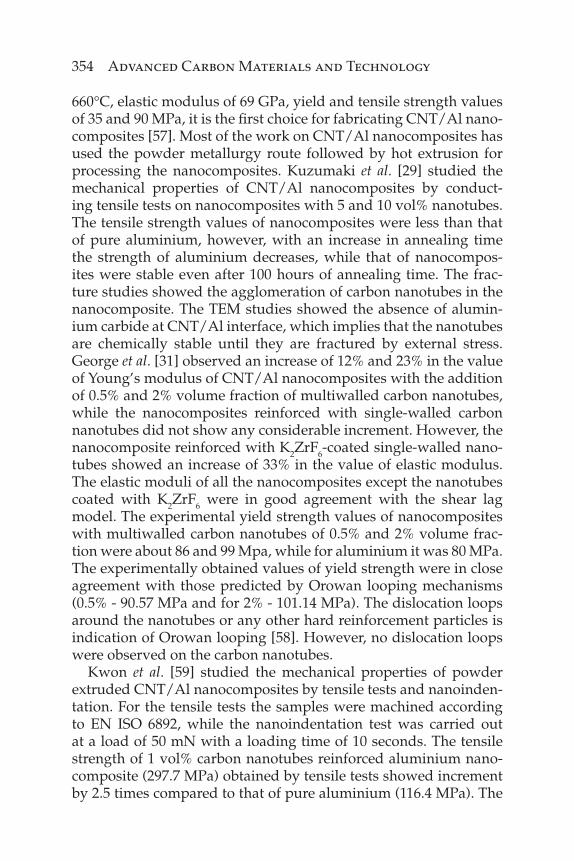
660°C, elastic modulus of 69 GPa, yield and tensile strength values of 35 and 90 MPa, it is the fi rst choice for fabricating CNT/Al nano-composites [57]. Most of the work on CNT/Al nanocomposites has used the powder metallurgy route followed by hot extrusion for processing the nanocomposites. Kuzumaki et al. [29] studied the mechanical properties of CNT/Al nanocomposites by conduct-ing tensile tests on nanocomposites with 5 and 10 vol% nanotubes. The tensile strength values of nanocomposites were less than that of pure aluminium, however, with an increase in annealing time the strength of aluminium decreases, while that of nanocompos-ites were stable even after 100 hours of annealing time. The frac-ture studies showed the agglomeration of carbon nanotubes in the nanocomposite. The TEM studies showed the absence of alumin-ium carbide at CNT/Al interface, which implies that the nanotubes are chemically stable until they are fractured by external stress. George et al. [31] observed an increase of 12% and 23% in the value of Young’s modulus of CNT/Al nanocomposites with the addition of 0.5% and 2% volume fraction of multiwalled carbon nanotubes, while the nanocomposites reinforced with single-walled carbon nanotubes did not show any considerable increment. However, the nanocomposite reinforced with K2ZrF6-coated single-walled nano-tubes showed an increase of 33% in the value of elastic modulus. The elastic moduli of all the nanocomposites except the nanotubes coated with K2ZrF6 were in good agreement with the shear lag model. The experimental yield strength values of nanocomposites with multiwalled carbon nanotubes of 0.5% and 2% volume frac-tion were about 86 and 99 Mpa, while for aluminium it was 80 MPa. The experimentally obtained values of yield strength were in close agreement with those predicted by Orowan looping mechanisms (0.5% - 90.57 MPa and for 2% - 101.14 MPa). The dislocation loops around the nanotubes or any other hard reinforcement particles is indication of Orowan looping [58]. However, no dislocation loops were observed on the carbon nanotubes.
Kwon et al. [59] studied the mechanical properties of powder extruded CNT/Al nanocomposites by tensile tests and nanoinden-tation. For the tensile tests the samples were machined according to EN ISO 6892, while the nanoindentation test was carried out at a load of 50 mN with a loading time of 10 seconds. The tensile strength of 1 vol% carbon nanotubes reinforced aluminium nano-composite (297.7 MPa) obtained by tensile tests showed increment by 2.5 times compared to that of pure aluminium (116.4 MPa). The
Metal Matrix Nanocomposites 355
yield strength of nanocomposites predicted using nanoindenta-tion stress-strain curve were constructed by setting the zero-load and displacement point with the theoretical estimates of the elastic moduli of the samples. The predicted yield strength values from nanoindentation were compared with that of tensile stress-strain curve and were found to be similar. However, the predictable yield strength from nanoindentation tests should be carefully consid-ered because this method is still not standardized. This technique is especially useful in cases where the materials are diffi cult to machine or in such cases where producing standard tensile speci-men is diffi cult.
Liu et al. [60] fabricated the CNT/Al 2009 nanocomposites by powder metallurgy, forging and subjecting them to friction stir pro-cessing (FSP). After FSP the samples were solutionized at 495°C for 2 hours, water quenched and then naturally aged for 4 days. The optical and SEM images of nanocomposites revealed that the large nanotube clusters were signifi cantly reduced by FSP and the nanotubes were individually dispersed inside the Al 2009 matrix. It was interesting to note that the forged nanocomposites with 1 and 3 wt% of nanotubes had a tensile strength of 392 and 298 Mpa, which were much less compared to that of unreinforced Al 2009 alloy. However, after subjecting to 4 pass FSP, the tensile strength values of both 1 and 3 wt% nanotubes reinforced nanocomposites were enhanced to 477 and 466 MPa when compared to that of Al 2009 alloy, which was 417 MPa. This was attributed to uniform dis-persion and grain refi nement by FSP. Lipecka et al. [61] reported the effect of temperature on the grain size as well as hardness of carbon nanotube reinforced aluminium alloy S790 (Al-Zn11-Mg2-Cu). The microstructure of extruded nanocomposite was analyzed using a scanning transmission electron microscope and Vickers hardness was measured using diamond indenter with 50 gm of load with force duration of 20 seconds. The nanotubes were successful in retarding grain growth of S790 alloy, as the grain mean diameter at 450°C annealing temperature was 566 nm compared to that of 500 nm at room temperature. With the addition of 3 wt% nanotubes the microhardness of nanocomposite (130 HV0.05) after 450°C saw a drop of 15% compared to annealing (150 HV0.05). The effect of nano-tube morphology and diameter on the mechanical properties of nanocomposites was studied [62]. Multiwalled carbon nanotubes of mean diameter 40 and 140 nm were added to pure aluminium with a content varying from 0.5, 1, 1.5, 2 and 5 wt.%. The tensile test
356 Advanced Carbon Materials and Technology
was conducted at a crosshead speed of 1 mm/min to obtain the ten-sile strength of unreinforced and CNT40 and CNT140/Al nanocom-posites. The hardness and Young’s modulus was measured using nanoindentation at a maximum indentation load of 700 mN. The tensile strength measured for CNT40/Al nanocomposites provided more strengthening than that of CNT140/Al nanocomposites for up to 1.5 wt% nanotubes. The nanoindentation results also showed that the nanotubes with 40 nm mean diameter provided more stiffening and hardness than that of nanotubes with 140 nm mean diameter. This can be due to easy and better dispersion of small diameter nanotubes in the aluminium matrix. The mechanical properties of cold sprayed CNT/Al-Si nanocomposite coatings were measured using nanoindentation by applying a load of 1000 μN and hold-ing for 2 seconds [63]. The elastic modulus and hardness of nano-composites were found to increase with an increase in nanotube content. With 1 wt% nanotube content in CNT/Al-Si nanocompos-ite, the elastic modulus and hardness was about 94.8 GPa and 0.64 GPa, while for unreinforced Al-Si alloy it was 45 GPa and 0.47 GPa, respectively. The strengthening of nanocomposites was attributed to the impediment of dislocation motion by nanotubes.
With new techniques like FSP, the breaking of nanotube clusters in the aluminium matrix with uniform dispersion and grain refi ne-ment are key factors for developing CNT/Al nanocomposites with better mechanical properties for applications in the automotive and aerospace industries.
9.4.2 CNT/Cu Nanocomposites
Most of the reports on the copper-reinforced carbon nanotubes have focused on the improvement in mechanical and thermal prop-erties. Almost all work on the fabrication of CNT/Cu nanocom-posites has been done using the powder metallurgy technique. The compressive tests of CNT/Cu nanocomposites fabricated by novel molecular mixing process were performed on an Instron machine with a crosshead speed of 0.2 mm/min [51]. The uniformly dis-persed nanotubes strengthened the copper matrix, which can be observed in the increment of yield strength and Young’s modulus values of the nanocomposites. The yield strength of unreinforced copper was 150 MPa while for nanocomposites with 5 and 10 vol% the values were 360 and 455 MPa. The elastic modulus of pure cop-per was increased from 82 GPa to 112 and 135 Gpa, respectively, for
Metal Matrix Nanocomposites 357
5 and 10 vol% nanotubes reinforced CNT/Cu nanocomposites. The strengthening in nanocomposites was due to better load transfer effi ciency and strong interfacial strength between nanotubes and copper matrix that originated from chemical bonds formed during molecular level processing.
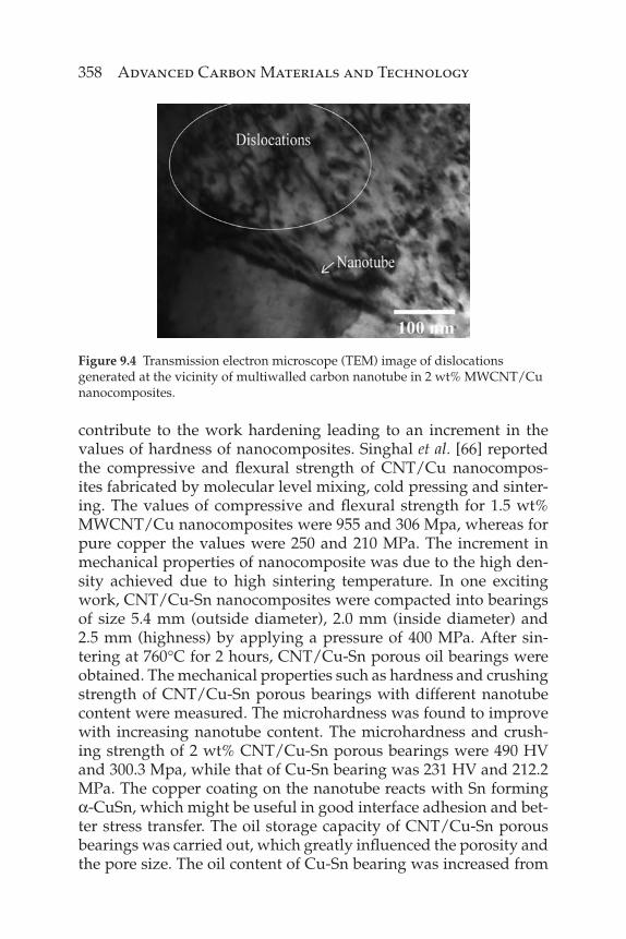
Li et al. [64] reported the development of CNT/Cu nanocompos-ites high strength coupled with good ductility. The mechanical prop-erties of high-pressure torsion processed CNT/Cu nanocomposites were carried in Hysitron Triboindenter nanoindenter. The samples of pillar shape for compression tests were prepared from focused ion beam (FIB) technique. The compression test on a pillar sample of 5 μm diameter and 11 μm length was carried out at a strain rate of 1×10⁻³ s-1. The yield strength of CNT/Cu and copper were 1125 and 738 Mpa, while plastic strains were 28.4% and 30.7%, respectively. In addition to this, the nanotubes located at both grain boundar-ies and grain interiors lead to grain refi nement and narrower grain size distribution. Koppad et al. [34] found that the Vickers hard-ness of multiwalled carbon nanotubes reinforced nanocomposites increased with an increase in nanotube content. The hardness of 4 wt% MWCNT/Cu nanocomposite (141 HV) was 2.04 times higher than that of unreinforced copper (69 HV). Obtaining the good inter-facial strength is necessary for better load transfer from matrix to carbon nanotube. In order to obtain a good bonding between cop-per matrix and carbon nanotube, Koppad et al. [33] applied nickel coating to the nanotubes. This was evident in the values of elas-tic modulus and hardness of the nanocomposites. Both the elastic modulus and hardness of the nanocomposites increased with an increase in nanotube content, and the values also showed better results with nickel-coated nanotubes. The hardness of pure copper was 0.95 Gpa, while that of uncoated and nickel-coated MWCNT/Cu nanocomposites with 3 wt% nanotubes were 1.33 and 1.46 GPa. Similarly, the elastic modulus of pure copper was 98 Gpa, while that of uncoated and nickel-coated MWCNT/Cu nanocomposites with 3 wt% nanotubes were 125 and 133 GPa. Apart from this the dislocation density in nanocomposites increased with the increas-ing nanotube content, which explains the strengthening by thermal mismatch model. Due to the coeffi cient of thermal expansion mis-match between copper (17×10–6 K-1) and carbon nanotube (1×10⁻⁶ K-1) the dislocations are generated around the nanotubes as shown in Figure 9.4. This results in punching of dislocations at the CNT/Cu interface leading to work hardening [65]. In this way nanotubes
358 Advanced Carbon Materials and Technology
contribute to the work hardening leading to an increment in the values of hardness of nanocomposites. Singhal et al. [66] reported the compressive and fl exural strength of CNT/Cu nanocompos-ites fabricated by molecular level mixing, cold pressing and sinter-ing. The values of compressive and fl exural strength for 1.5 wt% MWCNT/Cu nanocomposites were 955 and 306 Mpa, whereas for pure copper the values were 250 and 210 MPa. The increment in mechanical properties of nanocomposite was due to the high den-sity achieved due to high sintering temperature. In one exciting work, CNT/Cu-Sn nanocomposites were compacted into bearings of size 5.4 mm (outside diameter), 2.0 mm (inside diameter) and 2.5 mm (highness) by applying a pressure of 400 MPa. After sin-tering at 760°C for 2 hours, CNT/Cu-Sn porous oil bearings were obtained. The mechanical properties such as hardness and crushing strength of CNT/Cu-Sn porous bearings with different nanotube content were measured. The microhardness was found to improve with increasing nanotube content. The microhardness and crush-ing strength of 2 wt% CNT/Cu-Sn porous bearings were 490 HV and 300.3 Mpa, while that of Cu-Sn bearing was 231 HV and 212.2 MPa. The copper coating on the nanotube reacts with Sn forming α-CuSn, which might be useful in good interface adhesion and bet-ter stress transfer. The oil storage capacity of CNT/Cu-Sn porous bearings was carried out, which greatly infl uenced the porosity and the pore size. The oil content of Cu-Sn bearing was increased from
Figure 9.4 Transmission electron microscope (TEM) image of dislocations generated at the vicinity of multiwalled carbon nanotube in 2 wt% MWCNT/Cu nanocomposites.
Metal Matrix Nanocomposites 359
20.6% to 23.42% for 1 wt% nanotube reinforced CNT/Cu-Sn porous bearing [67].
These works clearly demonstrate that carbon nanotubes not only improved the yield strength or hardness of nanocomposites but also the oil storage capacity for lubrication performance of porous oil bearing.
9.4.3 CNT/Mg Nanocomposites
Magnesium and its alloys reinforced with particulate composites are very popular due to their easy fabrication, increased production and low reinforcement costs. However, the limited increment in tensile strength and ductility of particulate magnesium nanocom-posites and the call for better reinforcements have led to carbon nanotubes. To study the mechanical behavior of extruded carbon nanotube-added magnesium nanocomposites, macrohardness and tensile tests were conducted. The nanocomposites with 1.3 wt.% nanotube showed a better yield strength of 140 MPa with improved ductility of 13.5% compared to that of pure magnesium, which had values of 126 MPa and 8%. The presence of carbon nanotubes leads to activation of cross slip in non-basal slip planes, which was the main reason why the nanocomposites showed good ductility [54]. Addition of carbon nanotubes to the magnesium alloy ZK60A showed a decrease in the value of microhardness due to the for-mation of intermetallic phase in the matrix of the nanocomposite. However, an increase in the values of yield and tensile strength from 163 and 268 MPa for unreinforced ZK60A, to 180 and 295 MPa for 1 wt% CNT/ZK60A nanocomposite was observed. The compressive stress of nanocomposite (110 MPa) was found to be lower than that of unreinforced alloy (128 MPa). The drop was attributed to compressive shear buckling of carbon nanotubes in nanocomposite [55]. Li et al. [50] conducted the tensile studies on CNT/AZ 91 nanocomposites processed by casting and high pres-sure die casting. The nanocomposites showed that the compression at failure and compressive strength was enhanced with the addi-tion of nanotubes. No signifi cant increment in strength values were observed with the increasing amount of nanotubes. The mechani-cal properties of nanocomposites produced by pressure die casting such as tensile strength and elongation at fracture were increased from 8% and 27%, respectively, when compared to that of unrein-forced aluminium alloy.
360 Advanced Carbon Materials and Technology
An attempt was made to study the corrosion behavior of AZ31B magnesium alloy reinforced with carbon nanotubes [68]. For this immersion tests were performed to investigate the corrosion resis-tance of developed nanocomposites. The cylindrical samples of 12 mm diameter and 10 mm length were immersed in 1200 ml of 0.51 M sodium chloride (NaCl) solution at pH of 6.2. A polarization test was also carried out to study whether the nanocomposite samples were prone to Galvanic corrosion. The sample size taken for testing was 15×15×3, mm3 and was immersed in 75 ml of 0.017 M NaCl solution at 6.47 pH value and about 1 hour for stabilizing the sample surface. Signifi cant mass loss was observed in CNT/AZ31B nanocomposites after the immersion test in 0.51 M NaCl solution. Corrosion products such as Mg(OH)2 were observed in the vicinity of carbon nanotubes. The white debris of Mg(OH)2 piled around nanotubes was due to strong galvanic corrosion at the interfaces between nanotubes and the matrix. Here the surface potential difference was high enough to form the galvanic cell between the AZ31B alloy and nanotubes. Throughout testing the pH values of the nanocomposites tended to increase, and at one point in time reached a higher value than that of unreinforced alloy. This indeed decreased the corrosion resistance of nanotube reinforced AZ31B alloy.
9.4.4 CNT/Ti Nanocomposites
Titanium and its alloys are widely used in various applications due to their high specifi c strength and high corrosion resistance. Threrujirapapong et al. [69] reported the synthesis of carbon nano-tube reinforced fi ne (TiFine) and sponge titanium (TiSponge) pow-ders by spark plasma sintering and hot extrusion at 1000°C. The mechanical properties of hot-extruded CNT/TiFine nanocomposites such as yield stress, tensile strength and hardness were 592 MPa, 742 MPa and 285 HV0.05 compared to that of 423 MPa, 585 MPa and 261 HV0.05 for unreinforced TiFine. Similarly the mechanical proper-ties of CNT/TiSponge nanocomposites were enhanced due to addition of nanotubes. The increase in tensile strength values was attributed to the dispersion strengthening effect of nanotubes along with the in situ formed fi ne titanium carbide particles. In another work, Xue et al. [70] reported the elevated compressive properties of multi-walled carbon nanotubes reinforced titanium nanocomposites. The SPS processed nanocomposites showed the formation of TiC at the CNT/Ti interface. The compression test of nanocomposite
Metal Matrix Nanocomposites 361
was carried out at 800, 900 and 1000°C with a strain rate of 1×10⁻³ s-1. With the increasing sintering temperature, the initial compres-sive yield strength of 143 MPa at 800°C decreased to114 MPa at 900°C, and then a slight rise was observed at 1000°C (129 MPa). The higher sintering temperature of nanocomposites facilitates the reaction between nanotubes and titanium matrix leading to forma-tion of TiC at the interface. The formed TiC, however, had a lower strengthening effect compared to that of nanotubes, so the decrease in yield strength declined at elevated temperatures.
Other than the above mentioned metal matrices, metals like CNT/Ni nanocomposites were developed for better corrosion and wear resistance [71], CNT/Sn nanocomposites for improving the mechanical reliability of solder joints [72] and CNT/Ag nanocom-posites for heat dissipating systems [73].
9.5 Strengthening Mechanisms
Several hypotheses have been reported about the possible reinforc-ing mechanisms that could explain the improved mechanical prop-erties by addition of carbon nanotubes. Strengthening mechanisms of composites have been extensively studied by many researchers [74–78]. To study the direct strengthening of continuous fi ber-rein-forced composites, Cox et al. [79] developed the continuum shear lag model. This was followed by the prediction of yield strength of particle-reinforced metal matrix composites by considering the dislocations generated by the coeffi cient of thermal expansion mismatch [80]. The same strengthening mechanisms have been employed to study the strengthening effect of carbon nanotubes on the various properties of nanocomposites. However, it is important to note that the strengthening of nanocomposites can be attributed to the synergistic effect of thermal mismatch between carbon nano-tubes and metal matrix, grain refi nement due to the addition of carbon nanotubes and load transfer from the metal matrix to the carbon nanotubes. In this section we will discuss the strengthening mechanisms applied to nanocomposites by various authors.
George et al. [31] proposed three mechanisms to study the strengthening mechanism of CNT/Al nanocomposite. The strengthening mechanisms proposed were thermal mismatch, shear lag model and Orowan looping. The difference in coef-fi cient of thermal expansion between the carbon nanotube and
362 Advanced Carbon Materials and Technology
aluminium matrix results in generation of dislocations. Increased dislocation density promotes an increase in the yield strength of the nanocomposite. It is interesting to note that this model overes-timates the yield strength values compared to that of experimen-tal yield strength. For example, in the case of 2% volume fraction nanotube reinforced aluminium nanocomposite, the experimental yield strength obtained from tensile testing was 99 Mpa, while that by thermal mismatch model was 197.34 MPa. In Orowan loop-ing mechanism the dislocation motion is inhibited by the particles leading to the bending of dislocations around the particles forming dislocation loops. In this case the yield strength predicted (101.14 MPa) was close to the experimental value. However, TEM images showed the absence of the dislocation loops around the nanotubes. This was due to the collapse of dislocation loops at the interface of CNT/Al nanocomposite. The elastic moduli obtained by tensile tests (for 2% CNT/Al – 87.37 GPa) were in good agreement with that predicted by shear lag model (for 2% CNT/Al – 85.84 GPa). In their work, Bhat et al. [81] showed that the strengthening in CNT/Cu-Sn nanocomposites was due to the combined effect of thermal mismatch, load transfer and Orowan looping as the experimen-tal values were in close match with the values obtained by these strengthening models. Work on CNT/Al-Cu nanocomposites by Nam et al. [82] demonstrated an enhancement of 3.8 times in yield strength and 30% in elastic modulus compared with that of Al-Cu alloy. Two types of nanotubes, one with acid treatment and the other with PVA coating, were used. The difference between them is that the acid-treated nanotubes were shortened, with an aspect ratio of 14:20, and those that were PVA coated were undamaged, with an aspect ratio of 40:60. The yield strength of both acid-treated and PVA-coated CNT/Al-Cu nanocomposites was about 3.8 times higher than that of unreinforced Al-Cu alloy (376 and 384 MPa compared to 110 MPa). These results imply that regardless of nano-tube aspect ratio the strengthening effect of nanotubes is the same. The estimated elastic modulus values for nanocomposites by shear lag model were in good agreement with those of measured values. The strengthening mechanisms of nanocomposites varied with the aspect ratio of nanotubes. The fact that the acid-treated short nanotubes behaved as dispersed particles rather than a load trans-fer constituent suggests the dispersion strengthening mechanism in these nanocomposites. PVA-coated nanotubes with large aspect ratio exhibited the load transfer strengthening mechanism. But it
Metal Matrix Nanocomposites 363
is important to note that the increase in yield strength values is not only due to load transfer but also to dislocation related strengthen-ing mechanisms, which are thermal mismatch and Orowan loop-ing. Hence, it can be concluded that the strengthening of CNT/Al-Cu nanocomposite was mainly by the synergistic effect of all the strengthening mechanisms.
Strengthening of nanocomposites depends on processing tech-niques used, nanotube dispersion, effect of processing conditions on nanotubes and interface between nanotube and metal matrix. Most of the published data clearly shows that the strengthening of nanocomposites increases for small nanotube content, but at high nanotube concentration the strengthening effect is decreased.
9.6 Thermal Properties of Carbon Nanotube Reinforced Metal Matrix Nanocomposites
It is well known that copper is the second metal after silver that has a very high thermal conductivity of the order of 400 W/mK. Owing to this fact, copper and its alloys are used where high electrical and thermal conductivity are required. The pure copper which is nor-mally soft in nature is strengthened by adding reinforcement like tungsten particles, synthetic diamonds and carbon fi bers. Metal matrix composites such as CuW, CuMo, Cu-Gr and Cu-diamond are used as heat spreaders because of their good thermal conduc-tivity and low thermal expansion coeffi cient. However, these com-posite combinations have several drawbacks such as wettability, high cost of diamonds in the case of Cu-diamond composite, high density in the case of CuW and low machinability. In this context, carbon nanotubes possess very high thermal conductivity of the order of 3000 W/mK, low thermal expansion coeffi cient of 1×10⁻⁶ K-1 and a low density of 1.8 g/cm3. This has led to the development of CNT/Cu and CNT/Al nanocomposites for thermal manage-ment applications.
Kim et al. [83] have studied the thermal conductivity of nickel-coated carbon nanotubes reinforced copper nanocomposites fabri-cated by vacuum hot pressing technique. The thermal conductivity was measured using laser fl ash system with an ND:YAG pulse laser. This method was based on a measurement of the propagation of time of the heat produced by laser pulse and running from bot-tom to top of the sample. The nanocomposite in the form of a disc
364 Advanced Carbon Materials and Technology
was subjected to heating by using the laser beam. The temperature rise at the top of the disc was measured by infrared detector. The thermal conductivity was then calculated using the equation, k = α × ρ × Cp, where ρ is the density of nanocomposites and Cp is spe-cifi c heat. The thermal conductivity of pure copper obtained was close to 400 W/mK, but that of sintered Cu-Ni decreased to 150 W/mK, probably due to low thermal conductivity of nickel which is 91 W/mK. The thermal conductivity of nickel-coated CNT/Cu nanocomposite was dropped compared to that of Cu-Ni sample. Though these nanocomposites showed better mechanical proper-ties due to better interfacial bonding provided by nickel coating of the nanotubes, they did not improve the thermal properties. Chu et al. [35] reported the thermal conductivity of CNT/Cu nanocom-posites fabricated by SPS technique. It is observed that the ther-mal conductivity of CNT/Cu nanocomposites with 5 and 10 vol% nanotubes decreased slightly, but a large drop was observed in the case of nanocomposites with 15 vol% nanotubes. The drop in the thermal conductivity values was due to the interface thermal resis-tance between nanotube and copper matrix and poor dispersion and clustering of nanotubes in the copper matrix. The large drop in 15 vol% CNT/Cu nanocomposites was mainly due to large pores due to the clustering of nanotubes. In addition to this, due to pro-cessing conditions kinks or twists were produced in the nanotubes. The heat fl ows along the tube get blocked at these sites and contrib-ute to the low thermal conductivity.
After a few unsuccessful attempts, a few researchers have also reported on the development of CNT/Cu nanocomposites with better and improved thermal conductivity. Chai et al. [84] reported an increment of 180% in the thermal conductivity value of nano-composite. The CNT/Cu nanocomposite was prepared by electro-chemical deposition route with a thickness varying from 10 to 50 μm. To measure the thermal conductivity the authors developed a one-dimensional, steady thermal conduction setup. The tempera-ture sensors made up of platinum fi lm were used to measure the temperature gradient formed over the specimen. The measured thermal conductivity of pure copper and CNT/Cu nanocomposite was 339 and 604 W/mK. The obtained conductivity of pure copper was lower than that of bulk copper, which may be due to dimen-sion effects or the crystal structure resulting from the electrochemi-cal deposition process. It was also observed that an increase in the nanotube concentration in the electrolyte increases the thermal
Metal Matrix Nanocomposites 365
conductivity. With the nanotube concentration in the electrolyte increased from 50 mg/L to 250 mg/L, the conductivity of CNT/Cu nanocomposite increased from 441 to 637 W/mK. A possible explanation for this increase in the conductivity values includes good dispersion of nanotubes inside the electrolyte as well as in the deposited coating with good interfacial bonding with the copper matrix. The effect of surface treatment on carbon nanotubes, and in turn on the thermal conductivity of CNT/Cu nanocomposites, was studied by Cho et al. [85]. An amorphous carbon layer was observed on the surface pristine nanotubes. This layer was removed by treat-ing the nanotubes with different ratios (2:1 and 3:1) of sulfuric and nitric acid. The pristine and chemically treated nanotubes were added to copper. The thermal diffusivity of SPS fabricated nano-composites was carried out using laser fl ash technique at room temperature. The thermal conductivity of pure copper obtained was 348 W/mK. The chemically treated (3:1) MWCNT/Cu nano-composites (360 W/mK) showed better thermal conductivity then the treated (2:1) MWCNT/Cu nanocomposites (341 W/mK) and pristine MWCNT/Cu nanocomposites (336 W/mK). The low ther-mal conductivity values in the case of pristine MWCNT/Cu nano-composites were related to the copper oxide layer on the copper and amorphous carbon layer on nanotubes. The improved conduc-tivity values in the case of treated MWCNT/Cu nanocomposites were due to good interface bonding between nanotubes and copper with low interfacial thermal resistance.
Bakshi et al. [86] studied the thermal conductivity of CNT/Al-Si by both computations and experimentation. The experimental ther-mal conductivity value of plasma sprayed CNT/Al-Si nanocom-posite was 25.4 W/mK at 50°C, whereas for Al-Si alloy it was 73 W/mK. The low thermal conductivity values were due to inter-splat porosity and nanotube clusters. The object-oriented fi nite element method (OOF) was used to compute the thermal conductivity 10 wt% CNT/Al nanocomposite by employing different length scales. The study of microstructure on the small length scale of the order of microns and large length scale (hundreds of microns) was carried out. The OOF computed values were in good agreement with the experimental values. The predicted thermal conductivity values by OOF calculations at micro-length scale showed an increase of 81% in Al-Si matrix due to good dispersion of nanotubes, while at large length scale the thermal conductivity was low due to low thermal conductivity of nanotube clusters.
366 Advanced Carbon Materials and Technology
Still, a substantial amount of work has to be done to utilize these nanocomposites in the thermal management applications, which include uniform dispersion, unidirectional alignment of nanotubes, good bonding between nanotubes and metal matrix.
9.7 Tribological Properties of Carbon Nanotube Reinforced Metal Matrix Nanocomposites
Carbon materials like graphite are excellent solid lubricants. Carbon nanotubes which possess outstanding mechanical proper-ties are expected to provide self-lubrication. The graphene layers of nanotubes may offer lubrication during wear and can lower the coeffi cient of friction. Carbon nanotubes reinforced polymer and ceramic matrix nanocomposites have already shown reduction in friction and wear rates [87, 88]. An attempt to reduce the coeffi cient of friction and wear rate in metal matrix nanocomposites by adding carbon nanotubes has been carried out and has resulted in some encouraging results. The carbon nanotubes were added to metal matrices like nickel, copper and aluminium. Tu et al. [89] reported the tribological behavior of CNT/Cu nanocomposites. Before add-ing to copper, carbon nanotubes were coated with nickel by electro-less plating method. The friction and wear tests on nanocomposites were carried out using pin-on-disc machine (ASTM G99–90). With a sliding speed of 4.7×10⁻³ m/s and loads between 10–50 N, the weight loss was measured after each testing. The values of coef-fi cient of friction for unreinforced copper were in between 0.2 to 0.27, while for nanocomposites they were in the range of 0.096 and 0.19 N. This was attributed to reduced contact between metal-lic matrix and diamond due to the presence of carbon nanotubes. The nanotubes lubricating property also contributed to a decrease in the values of friction coeffi cient. However, the nanocomposites with the highest volume percentage (Cu-16 vol% CNTs) showed severe wear due to the presence of high porosity, and wear rate increased rapidly at higher load. The worn surfaces observed by SEM showed that cracking and spalling were the principal wear mechanisms for the nanocomposites with higher nanotube vol-ume percent. In another work, the copper-coated carbon nanotubes reinforced copper matrix nanocomposites fabricated by microwave sintering technique were subjected to a pin-on-disc test to study their tribological characteristics [90]. The loads in the range of 10
Metal Matrix Nanocomposites 367
to 60 N were applied by maintaining the sliding speed of 2.77 m/s. A gradual reduction in wear rate was observed with the increas-ing nanotube volume fraction. However, due to agglomeration of nanotubes, a decrease in the value of hardness and increase in wear rate were observed in the case of nanocomposites with nano-tubes beyond 15 vol%. Similarly, the coeffi cient of friction was less in the case of nanocomposites with up to 15 vol% carbon nano-tube, beyond which an increase in coeffi cient friction was observed. With the formation of carbonaceous fi lm at the contact surface, the direct contact between the nanocomposite and steel disc was avoided. Due to the self-lubricating property of the fi lm formed, the adhesion between the contacting surfaces was reduced. At high operating loads, the wear mechanisms observed for low and high nanotube volume fraction nanocomposites were plastic deforma-tion and fl ake formation-spalling.
A lot of work has been carried out on improving the wear and corrosion resistance of various substrates by electrodepositing CNT/Ni nanocomposite coating over them. For example, alumin-ium alloys are widely used in a variety of applications, but the matter of their poor wear resistance is of concern. To address this problem, Tu et al. [91] studied the friction and wear properties of CNT/Ni nanocomposite-coated LY12 Al alloy (4.4%Cu-1.5%Mg-0.6%Mn and rest Al). The friction and wear tests were carried out on pin-on-disc tester under dry sliding conditions with a sliding speed of 0.0623 m/s and at a load range of 12 to 150 N. The results revealed that the wear rates of nanocomposite coatings were found to decrease with increasing nanotube volume fraction at lower applied loads. The wear rates of nanocomposites rapidly increased with applied loads of more than 120 N. The worn sur-face analysis of the nanocomposites with higher nanotube con-tent showed the cracking and spalling at higher applied loads. The coeffi cient of friction of all the nanocomposites decreased with increasing nanotube content. The authors attributed this to prevention of metal to metal contact by nanotubes which would slide or roll between CNT/Ni-coated disc and the steel pin. Chen et al. [92] studied the friction and wear properties of CNT/Ni-P nanocomposite coating prepared by electroless codeposition using ring-on-block apparatus under lubricated condition. The nanocomposite coating was applied on the test ring and block specimen of medium carbon steel. The wear tests were conducted at a sliding speed of 2.06 m/s. Prior to wear tests some of the
368 Advanced Carbon Materials and Technology
nanocomposite coatings were heat treated at 400°C for 2 hours in vacuum. The wear rate of CNT/Ni-P nanocomposite coating was about one-fi fth of that of unreinforced Ni-P coating. The wear resistance of nanocomposites further improved after heat treat-ment due to the formation Ni3P phase. The worn surfaces of unre-inforced Ni-P coating showed some severe wear scars while very few scars were observed in nanotube-reinforced Ni-P coating. The friction coeffi cient of CNT/Ni-P coatings was greatly reduced due to short nanotubes, which were easy to shear and slide in between the metal-metal friction surfaces. Bakshi et al. [93] studied the nanoscratch behavior of 5 and 10 wt% carbon nanotube-rein-forced Al-Si nanocomposite coatings by Triboindenter. Scratches of length 20 μm were made at loads 1000, 2000 and 3000 μN at a scratching speed of 0.67 μm/s. The nanoscratch tests carried out on nanocomposite coatings revealed the scratch formation by a ploughing kind of mechanism in which the materials displaced accumulated on the sides of the scratch. It was observed that the width of scratches increased with increasing load. The wear vol-ume, however, was found to decrease with an increase in nano-tube content. This is due to the addition of nanotubes which helps to increase the hardness values of nanocomposite coatings. The increased hardness with increase in nanotube content resulted in a reduction in contact depth and wear volume. This was due to uniform dispersion and better strengthening of nanocomposite coatings by the addition of carbon nanotubes.
Although the carbon nanotube reinforced metal matrix nanocom-posites have shown good wear resistance and low coeffi cient of fric-tion, there are some areas which have to be addressed. Optimized parameters of nanotube content and its dispersion are required for development of nanocomposite coating with better properties.
9.8 Challenges
The discovery of carbon nanotubes have opened up a new era in the fi eld of nanotechnology. These nanoscale materials have shown tremendous promise in the development of nanocomposites with multifunctional properties. Either in conducting polymers or high fracture strength ceramics or high strength and high conductivity metal, nanocomposites containing carbon nanotubes are a near-term application. However, there are certain technological issues
Metal Matrix Nanocomposites 369
pertaining to carbon nanotubes which are uniform dispersion, wet-tability, and alignment in the matrix and the interface.
The fi rst and foremost problem that the carbon nanotubes-based metal matrix nanocomposites are facing is uniform dispersion. Due to large aspect ratio and strong van der Waal force of attrac-tion, carbon nanotubes tend to form clusters. These clusters tend to reduce either the mechanical or thermal properties of the nano-composites [29, 86]. For example, CNT/Cu nanocomposites have shown a drop in thermal conductivity values due to the agglom-eration of carbon nanotubes [35]. Several studies on carbon nano-tubes fi lms have reported very low conductivity values. Yang et al. [18] investigated the thermal conductivity of carbon nanotube fi lms of thickness varying from 10 to 50 μm. The average thermal conductivity values of these fi lms were about 15 W/mK. Gong et al. [94] measured the thermal conductivity of aligned CNT/carbon composite prepared by CVD deposition of carbon on nanotubes. The values measured were in between 10 to 75 W/mK. To address this problem several authors have suggested functionalization by chemical treatment, ball milling, and multi-step secondary process-ing. Yang et al. [95] reported homogeneous dispersion of nanotubes in aluminium powder. The process involved nickel deposition on aluminum powders followed by in situ synthesis of nanotubes in these powders by CVD. The microstructural characterization of these powders showed even dispersion of nanotubes on the surface of aluminium powder. Most of the nanotubes had good bonding between the aluminium as most ends of separate nanotubes were implanted into aluminium powder. Singhal et al. [96] carried out amino functionalization of carbon nanotubes to improve its disper-sion in aluminium matrix. The functionalization was carried out by ball milling carbon nanotubes in the presence of ammonium bicarbonate. The formation of nanosized Al4C3 at the interface helped to improve the stress transfer effi ciency. In addition to this, the presence of amine and amide groups on the nanotube surface decreased the van der Waals force of attraction between them. The functionalized carbon nanotubes reinforced aluminium nanocom-posites showed better dispersion and good mechanical properties compared to that of pure nanotubes reinforced nanocomposites.
The second problem related to nanocomposites is wettability of carbon nanotubes with metal matrix. Work by Dujardin et al. [19] has shown that the carbon nanotubes cannot easily wet metals with high surface tension. It is necessary for a reinforcement and matrix
370 Advanced Carbon Materials and Technology
material to have good interfacial bonding. The interfacial bond-ing between carbon nanotubes and metal matrix can be improved by subjecting carbon nanotubes to surface treatments. It has been shown by several authors that the nanotubes coated with either copper or nickel by electroless plating technique could decrease the interface energy between nanotubes and metal matrix, and increase the interfacial bonding strength and the nanocomposites with improved properties [97, 98].
The third factor is alignment of carbon nanotubes inside the metal matrices. It is well known that the thermal conductivity of carbon nanotubes is very high along the tube direction but very low in the radial direction. It is necessary that the nanocompos-ites for thermal management applications should display the iso-tropic behavior rather than anisotropic material properties. For this the nanotubes have to be oriented in a particular direction and should avoid random orientation. A research work by Chai et al. [99] reported the fabrication of CNT/Cu nanocomposites on silicon substrate by electrochemical plating method. The copper was deposited on the substrates having aligned nanotubes. Both thermal and electrical resistance decreased by increasing copper loading into the aligned nanotubes. The change in the resistance was attributed to improved contact between nanotube and cop-per metal. The thermal resistance of silicon and aluminium sub-strate showed very high and higher contact pressure dependence, whereas the copper-fi lled aligned carbon nanotube nanocompos-ites showed much smaller interface resistance and were less depen-dent on the contact pressure.
The last important factor is the interface between carbon nano-tubes and metal matrix. The interface plays an important role in load transfer from matrix to the nanotube and crack defl ection. The formation of nanosized layers of Al4C3 and MgC2 in CNT/Al and CNT/Mg nanocomposites have shown the better load transfer from the matrix phase to carbon nanotubes by pinning the nanotubes to the matrix material [100, 101]. But in a few cases the observed incre-ment in the mechanical properties could be minimal. Hence, it is necessary to carry out the thermodynamic analysis to predict the interfacial reaction between the two constituents’ matrix and nano-tubes to ensure better bonding and load transfer [102].
After successfully addressing these problems one can obtain very high quality nanocomposite that will have some real-life applica-tions either in heat sinks or load-bearing members.
Metal Matrix Nanocomposites 371
9.9 Concluding Remarks
The discovery of the revolutionary material known as carbon nano-tubes has stimulated much interest in their use to reinforce metal matrix. The development of nanocomposites with this nanoscale fi ller material has been a topic of intense research in the past decades owing to its outstanding mechanical, thermal and tribo-logical properties. Already many potential applications of metal matrix nanocomposites have been projected covering the aerospace industry to electronic packaging. However, carrying out a system-atic study in this fi eld is broad in scope and includes, for example, uniform dispersion of nanotubes, wettability, alignment in metal matrix and the interface design. New models need to be formulated to predict the mechanical and physical properties by accounting for their agglomeration and defects.
References
1. B. Bhushan, Introduction to nanotechnology, in: B. Bhushan, ed., Springer Handbook of Nanotechnology, Springer-Verlag Berlin Heidelberg, pp. 1–6, 2004.
2. P.M. Ajayan, Bulk metal and ceramics nanocomposites, in: P.M. Ajayan, L.S. Schadler, and P.V. Braun, eds., Nanocomposite Science and Technology, Wiley-VCH Verlag GmbH & Co. KGaA, Weinheim, pp. 1–75, 2003.
3. A. Agarwal, S.R. Bakshi, D. Lahiri, Carbon Nanotubes - Reinforced Metal Matrix Composites, CRC Press, Taylor and Francis Group, LLC, 2011.
4. S.H. Pezzin, S.C. Amico, L.A.F. Coelho, and M.J. de Andrade, Nanoreinforcements for nanocomposite materials, in: C.P. Bergmann and M.J. de Andrade, eds., Nanostructured Materials for Engineering Applications, Springer-Verlag Berlin Heidelberg, pp. 119–131, 2011.
5. H.W. Kroto, J.R. Heath, S.C. O’Brien, R.F. Curl, and R.E. Smalley, Nature, Vol. 318, p. 162, 1985.
6. S. Iijima, Nature, Vol. 354, p. 56, 1991. 7. S. Iijima and T. Ichihashi, Nature, Vol. 363, p. 603, 1993. 8. D.S. Bethune, C.H. Kiang, M.S. de Vries, G. Gorman, R. Savoy, J.
Vazquez, and R. Bayers, Nature, Vol. 363, p. 605, 1993. 9. C.N.R. Rao and A. Govindaraj, Nanotubes and Nanowires, The Royal
Society of Chemistry Publishing, Cambridge, 2005. 10. R.S. Ruoff and D.C. Lorents, Carbon, Vol. 33, p. 925, 1995. 11. G. Overney, W. Zhong, and D. Tomanek, Zeitschrift fur Physik D:
Atoms, Molecules, and Clusters, Vol. 27, p. 93, 1993.
372 Advanced Carbon Materials and Technology
12. J.P. Lu, Physical Review Letters, Vol. 79, p. 1297, 1997. 13. K.T. Kashyap and R.G. Patil, Bulletin of Materials Science, Vol. 31,
p. 185, 2008. 14. M.-F. Yu, O. Lourie, M.J. Dyer, K. Moloni, T.F. Kelly, and R.S. Ruoff,
Science, Vol. 287, p. 637, 2000 15. M.-F. Yu, B.S. Files, S. Arepalli, and R.S. Ruoff, Physical Review Letters,
Vol. 84, p. 5552, 2000. 16. S. Berber, Y.-K. Kwon, and D. Tomanek, Physical Review Letters,
Vol. 84, p. 4613, 2000. 17. P. Kim, L. Shi, A. Majumdar, and P.L. McEuen, Physical Review Letters,
Vol. 87, p. 215502, 2001. 18. D.J. Yang, Q. Zhang, G. Chen, S.F. Yoon, J. Ahn, S.G. Wang, Q. Zhou,
Q. Wang, and J.Q. Li, Physical Review B, Vol. 66, p. 165440, 2002. 19. E. Dujardin, T.W. Ebbesen, H. Hiura, and K. Tanigaki, Science, Vol. 265,
p. 1850, 1994. 20. S.S. Wong, J.D. Harper, P.T. Lansbury Jr., and C.M. Lieber, Journal of
American Chemical Society, Vol. 120, p. 603, 1998. 21. W.B. Choi, D.S. Chung, J.H. Kang, H.Y. Kim, Y.W. Jin, I.T. Han, Y.H.
Lee, J.E. Jun, N.S. Lee, G.S. Park, and J.M. Kim, Applied Physics Letters, Vol. 75, p. 3129, 1999.
22. J. Kong, N.R. Franklin, C. Zhou, M.G. Chapline, S. Peng, K. Cho, and H. Dai, Science, Vol. 287, p. 622, 2000.
23. A. Bianco, K. Kostarelos, and M. Prato, Current Opinion in Chemical Biology, Vol. 9, p. 674, 2005.
24. R.H. Baughman, A.A. Zakhidov, and W.A. de Heer, Science, Vol. 297, p. 787, 2002.
25. S.C. Tjong, Carbon Nanotube Reinforced Composites - Metal and Ceramic Matrices, Wiley-VCH Verlag GmbH & Co. KGaA, Weinheim, 2009.
26. W.A. Curtin and B.W. Sheldon, Materials Today, p. 44, November 2004. 27. S.R. Bakshi, D. Lahiri, and A. Agarwal, International Materials Reviews,
Vol. 55, p. 41, 2010. 28. P.G. Koppad, Multiwalled carbon nanotubes in novel metal matrix
nanocomposites, International Conference on Advanced Materials, Manufacturing, Management and Thermal Sciences, Organized by Siddaganga Institute of Technology, Tumkur, India, p. 57, 2013.
29. T. Kuzumaki, K. Miyazawa, H. Ichinose, and K. Ito, Journal of Materials Research, Vol. 13, p. 2445, 1998.
30. W.X. Chen, J.P. Tu, L.Y. Wang, H.Y. Gan, Z.D. Xu, and X.B. Zhang, Carbon, Vol. 41, p. 215, 2003.
31. R. George, K.T. Kashyap, R. Rahul, and S. Yamdagni, Scripta Materialia, Vol. 53, p. 1159, 2005.
32. A.M.K. Esawi, and K. Morsi, Composites Part A, Vol. 38, p. 646, 2007. 33. P.G. Koppad, H.R.A. Ram, and K.T. Kashyap, Journal of Alloys and
Compounds, Vol. 549, p. 82, 2013.
Metal Matrix Nanocomposites 373
34. P.G. Koppad, K.T. Kashyap, V. Shrathinth, T.A. Shetty, and R.G. Koppad, Materials Science and Technology, Vol. 29, p. 605, 2013.
35. K. Chu, Q. Wua, C. Jia, X. Liang, J. Nie, W. Tian, G. Gai, and H. Guo, Composites Science and Technology, Vol. 70, p. 298, 2010.
36. H.J. Choi, B.H. Min, J.H. Shin, and D.H. Bae, Composites Part A, Vol. 42, p. 1438, 2011.
37. H.R.A. Ram, P.G. Koppad, and K.T. Kashyap, Materials Science and Engineering A, Vol. 559, p. 920, 2013.
38. K.T. Kashyap, K.B. Puneeth, A. Ram, and P.G. Koppad, Materials Science Forum, Vol. 710, p. 780, 2012.
39. Y.D. Han, S.M.L. Nai, H.Y. Jing, L.Y. Xu, C.M. Tan, and J. Wei, Journal of Materials Science: Materials for Electronics, Vol. 22, p. 315, 2011.
40. Z.H. Li, X.Q. Wang, M. Wang, F.F. Wang, and H.L. Ge, Tribology International, Vol. 39, p. 953, 2006.
41. W.M. Daoush, B.K. Lim, C.B. Mo, D.H. Nam, and S.H. Hong, Materials Science and Engineering A, Vol. 513–514, p. 247, 2009.
42. X.H. Chen, F.Q. Cheng, S.L. Li, L.P. Zhou, and D.Y. Li, Surface and Coatings Technology, Vol. 155, p. 274, 2002.
43. C. Guo, Y. Zuo, X. Zhao, J. Zhao, and J. Xiong, Surface and Coatings Technology, Vol. 202, p. 3385, 2008.
44. C.S. Ramesh, M.P. Harsha, K.S. Nagendra, and Z. Khan, Development of nickel-CNT electro-composites, Society of Tribologists and Lubrication Engineers Annual Meeting and Exhibition 2012, St. Louis, Missouri, USA, p. 165, 2012.
45. T. Laha, A. Agarwal, T. McKechnie, and S. Seal, Materials Science and Engineering A, Vol. 381, p. 249, 2004.
46. T. Laha, Y. Liu, and A. Agarwal, Journal of Nanoscience and Nanotechnology, Vol. 7, p. 1, 2007.
47. S.R. Bakshi, V. Singh, K. Balani, D.G. McCartney, S. Seal, and A. Agarwal, Surface and Coatings Technology, Vol. 202, p. 5162, 2008.
48. S. Cho, K. Takagi, H. Kwon, D. Seo, K. Ogawa, K. Kikuchi, and A. Kawasaki, Surface and Coatings Technology, Vol. 206, p. 3488, 2012.
49. Q. Li, A. Viereckl, C.A. Rottmair, and R.F. Singer, Composites Science and Technology, Vol. 69, p. 1193, 2009.
50. Q. Li, C.A. Rottmair, and R.F. Singer, Composites Science and Technology, Vol. 70, p. 2242, 2010.
51. S.I. Cha, K.T. Kim, S.N. Arshad, C.B. Mo, and S.H. Hong, Advanced Materials, Vol. 17, p. 1377, 2005.
52. Y. Morisada, H. Fujii, T. Nagaoka, and M. Fukusumi, Materials Science and Engineering A, Vol. 419, p. 344, 2006.
53. D.K. Lim, T. Shibayanagi, and A.P. Gerlich, Materials Science and Engineering A, Vol. 507, p. 194, 2009.
54. C.S. Goh, J. Wei, L.C. Lee, and M. Gupta, Materials Science and Engineering A, Vol. 423, p. 153, 2006.
374 Advanced Carbon Materials and Technology
55. M. Paramsothy, J. Chan, R. Kwok, and M. Gupta, Composites Part A, Vol. 42, p. 180, 2011.
56. M.-F. Yu, Journal of Engineering Materials and Technology, Vol. 126, p. 271, 2004.
57. W.D. Callister Jr., Fundamentals of Materials Science and Engineering, John Wiley & Sons, Inc., USA, 2001.
58. D. Lahiri, S.R. Bakshi, A.K. Keshri, Y. Liu, and A. Agarwal, Materials Science and Engineering A, Vol. 523, p. 263, 2009.
59. H. Kwon and M. Leparoux, Nanotechnology, Vol. 23, p. 415701, 2012. 60. Z.Y. Liu, B.L. Xiao, W.G. Wang, and Z.Y. Ma, Carbon, Vol. 50, p. 1843,
2012. 61. J. Lipecka M. Andrzejczuk, M. Lewandowska, J. Janczak-Rusch, and K.J.
Kurzydłowski, Composites Science and Technology, Vol. 71, p. 1881, 2011. 62. A.M.K. Esawi, K. Morsi, A. Sayed, M. Taher, and S. Lanka, Composites
Part A, Vol. 42, p. 234, 2011. 63. Y. Chen, S.R. Bakshi, and A. Agarwal, Surface and Coatings Technology,
Vol. 204, p. 2709, 2010. 64. H. Li, A. Misra, Z. Horita, C.C. Koch, N.A. Mara, P.O. Dickerson, and
Y. Zhu, Applied Physics Letters, vol. 95, p. 071907, 2009. 65. K.T. Kashyap, C. Ramachandra, C. Dutta, and B. Chatterji, Bulletin of
Materials Science, Vol. 23, p. 47, 2000. 66. S.K. Singhal, M. Lal, I. Sharma, and R.B. Mathur, Journal of Composite
Materials, Vol. 47, p. 613, 2013. 67. L. Jun, L. Ying, L. Lixian, and Y. Xuejuan, Composites Part B, Vol. 43,
p. 1681, 2012. 68. H. Fukuda, J.A. Szpunar, K. Kondoh, and R. Chromik, Corrosion
Science, Vol. 52, p. 3917, 2010. 69. T. Threrujirapapong, K. Kondoh, H. Imai, J. Umeda, and B. Fugetsu,
Transactions of Joining and Welding Research Institute, Vol. 37, p. 57, 2008.
70. F. Xue, S. Jiehe, F. Yan, and C. Wei, Materials Science and Engineering A, Vol. 527, p. 1586, 2010.
71. X.H. Chen, C.S. Chen, H.N. Xiao, H.B. Liu, L.P. Zhou, S.L. Li, and G. Zhang, Tribology International, Vol. 39, p. 22, 2006.
72. E.K. Choi, K.Y. Lee, and T.S. Oh, Journal of Physics and Chemistry of Solids, Vol. 69, p. 1403, 2008.
73. C. Edtmaier, T. Steck, R.C. Hula, L. Pambaguian, and F. Hepp, Composites Science and Technology, Vol. 70, p. 783, 2010.
74. M. Taya, Materials Transactions, Vol. 32, p. 1, 1991. 75. W.S. Miller and F.J. Humphreys, Scripta Metallurgica et Materialia,
Vol. 25, p. 33, 1991. 76. F. Tang, I.E. Anderson, T.G. Herold, and H. Prask, Materials Science
and Engineering A, Vol. 383, p. 362, 2004.
Metal Matrix Nanocomposites 375
77. A.Z. Yazdi, R. Bagheri, S.M. Zebarjad, and Z.R. Hesab, Advanced Composite Materials, Vol. 19, p. 299, 2010.
78. S.R. Bakshi and A. Agarwal, Carbon, Vol. 49, p. 533, 2011. 79. H.L. Cox, British Journal of Applied Physics, Vol. 3, p. 73, 1952. 80. R.J. Arsenault, N. Shi, Materials Science and Engineering, Vol. 81, p. 175,
1986. 81. A. Bhat, V.K. Balla, S. Bysakh, D. Basu, S. Bose, and A. Bandyopadhyay,
Materials Science and Engineering A, Vol. 528, p. 6727, 2011. 82. D.H. Nam, S.I. Cha, B.K. Lim, H.M. Park, D.S. Han, and S.H. Hong,
Carbon, Vol. 50, p. 2417, 2012. 83. C. Kim, B. Lim, B. Kim, U. Shim, S. Oh, B. Sung, J. Choi, J. Ki, and S.
Baik, Synthetic Metals, Vol. 159, p. 424, 2009. 84. G. Chai and Q. Chen, Journal of Composite Materials, Vol. 44, p. 2863,
2010. 85. S. Cho, K. Kikuchi, and A. Kawasaki, Acta Materialia, Vol. 60, p. 726,
2012. 86. S.R. Bakshi, R.R. Patel, and A. Agarwal, Computational Materials
Science, Vol. 50, p. 419, 2010. 87. W.X. Chen, F. Li, G. Han, J.B. Xia, L.Y. Wang, J.P. Tu, and Z.D. Xu,
Tribology Letters, Vol. 15, p. 275, 2003. 88. G.D. Zhan, J.D. Kuntz, J.L. Wan, and A.K. Mukherjee, Nature Materials,
Vol. 2, p. 38, 2003. 89. J.P. Tu, Y.Z. Yang, L.Y. Wang, X.C. Ma and X.B. Zhang, Tribology
Letters, Vol. 10, p. 225, 2001. 90. K. Rajkumar and S. Aravindan, Wear, Vol. 270, p. 613, 2011. 91. J.P. Tu, L.P. Zhu, W.X. Chen, X.B. Zhao, F. Liu, and X.B. Zhang,
Transactions of Nonferrous Metals Society of China, Vol. 14, p. 880, 2004. 92. W.X. Chen, J.P. Tu, Z.D. Xu, W.L. Chen, X.B. Zhang, and D.H. Cheng,
Materials Letters, Vol. 57, p. 1256, 2003. 93. S.R. Bakshi, D. Lahiri, R.R. Patel, and A. Agarwal, Thin Solid Films,
Vol. 518, p. 1703, 2010. 94. Q-M. Gong, Z. Li, X.-D. Bai, D. Li, Y. Zhao, and J. Liang, Materials
Science and Engineering A, Vol. 384, p. 209, 2004. 95. X. Yang, C. Shi, C. He, E. Liu, J. Li, and N. Zhao, Composites Part A,
Vol. 42, p. 1833, 2011. 96. S.K. Singhal, R. Pasricha, M. Jangra, R. Chahal, S. Teotia, and R.B.
Mathur, Powder Technology, Vol. 215–216, p. 254, 2012. 97. B. Lim, C.-J Kim, B. Kim, U. Shim, S. Oh, B.-H. Sung, J.-H. Choi, and
S. Baik, Nanotechnology, Vol. 17, p. 5764, 2006. 98. M. Schneider, M. Weiser, S. Dorfl er, H. Althues, S. Kaskel, and A.
Michaelis, Surface Engineering, Vol. 28, p. 435, 2012. 99. Y. Chai, K. Zhang, M. Zhang, P.C.H. Chan, and M.M.F. Yuen, IEEE
Electronic Components and Technology Conference, p. 1224, 2007.

376 Advanced Carbon Materials and Technology
100. H. Kwon, M. Estili, K. Takagi, T. Miyazaki, and A. Kawasaki, Carbon, Vol. 47, p. 570, 2009.
101. C.S. Goh, J. Wei, L.C. Lee, and M. Gupta, Nanotechnology, Vol. 17, p. 7, 2006.
102. S.R. Bakshi, A.K. Keshri, V. Singh, S. Seal, and A. Agarwal, Journal of Alloys and Compounds, Vol. 481, p. 207, 2009.


![Carbon Nanotubes and Semiconducting Polymer Nanocomposites · 2018-09-25 · Carbon Nanotubes and Semiconduc ting Polymer Nanocomposites 471 ion mass transfer [28]. In some host polymers,](https://img.pdfslide.net/doc/110x75/5f42727e6bc30357fd01dba3/carbon-nanotubes-and-semiconducting-polymer-nanocomposites-2018-09-25-carbon-nanotubes.jpg)