Embed Size (px)
Citation preview

Part 1
GRAPHENE, CARBON NANOTUBES AND FULLERENES
Ashutosh Tiwari and S.K. Shukla (eds.) Advanced Carbon Materials and Technology, (1–34) 2014 © Scrivener Publishing LLC

3
Ashutosh Tiwari and S.K. Shukla (eds.) Advanced Carbon Materials and Technology, (1–34) 2014 © Scrivener Publishing LLC
1
Synthesis, Characterization and Functionalization of Carbon
Nanotubes and Graphene: A Glimpse of Their Application
Mahe Talat and O.N. Srivastava*
Nanoscience and Nanotechnology Unit, Department of Physics, Banaras Hindu University, Varanasi, India
AbstractSince the discovery of nanomaterials, carbon nanotubes structures have attracted great interest in most areas of science and engineering due to their unique physical and chemical properties and are supposed to be a key component of nanotechnology. The most recent addition to the family of carbon nanostructures is graphene. Graphene is a one-atom-thick material consisting of sp2-bonded carbon with a honeycomb structure. It resembles a large polyaromatic molecule of semi-infi nite size. In the past fi ve years, graphene-based nanomaterials have been the focus of not only material scientists but also engineers and medical scientists. The interesting and exciting properties of single-layer graphene sheets have excited the sci-entifi c community especially in the areas of materials, physics, chemistry and medical science. The state-of-the-art CNT production encompasses numerous methods and new routes are continuously being developed. The most common synthesis techniques are arc discharge, laser ablation, high pressure carbon monoxide (HiPCO) and chemical vapor deposition (CVD) with many variants. Most of these processes take place in vacuum or with process gases. By choosing appropriate experimental parameters, large quantities of nanotubes can be synthesized by these methods. It is possible to control some properties of the fi nal product, such as type of CNTs synthesized (MWNTs vs. SWNTs), the quality of the nanotubes,
*Corresponding author: [email protected]

4 Advanced Carbon Materials and Technology
the amount and type of impurities, and some structural CNT features. In this chapter we discuss some of the methods employed in our lab for the synthesis and characterization of the CNTs and graphene. For appli-cation in biomedical and targeted drug delivery, the major limitation of these nanomaterials is their poor solubility, agglomeration and processi-bility. Functionalization of CNTs and GS is, therefore, necessary to attach any desired compounds including drug and also to enhance the solubility and biocompatibility of these nanomaterials. Two types of functionaliza-tion methods, i.e., covalent and non-covalent methods are generally being adopted. We deliberate these two procedures of functionalization of CNTs and GS. The merits of these two modes of functionalization will also be discussed.
Keywords: Synthesis, characterization, application, CNT, graphene
1.1 Introduction
Carbon is the base element of all organic materials, one of the most abundant elements on earth and also the only element of the periodic table that occurs in allotropic forms from 0 dimensions to 3 dimensions due to its different hybridization capabilities. It has the unique ability to form allotropes, which can be described by valence bond hybridization, spn. The well-known forms are diamond, where n = 3, and graphite, having n = 2. It was shown that all other 1<n<3 are possible. The valence bond hybridiza-tion determines the physical and chemical properties of the allo-tropes of carbon. Fullerene (zero-dimensional), carbon nanotubes (one-dimensional) and graphene (single layer of graphite, two-dimensional) are all made of sp2-hybridized carbon atoms, whereas diamond (three-dimensional) is sp3 hybridized. The discovery of “fullerenes” added a new dimension to the knowledge of carbon science, which led to the Nobel Prize being awarded to R.F. Curl, H. Kroto and R.E. Smalley in 1996. Stimulated by fullerene discover-ies, the Japanese scientist Ijima [1] discovered another new form of carbon-graphitic tubules and the CNT was born. He also suggested the possible structure of these tubes, which was later proven right. The subsequent discovery of “carbon nanotubes” (CNTs) added a new dimension to the science and technology of new carbons.
The most recent addition to the family of carbon nanostructures is graphene. Graphene is a one-atom-thick material consisting of sp2-bonded carbon with a honeycomb structure. It resembles a large

Synthesis, Characterization and Functionalization 5
polyaromatic molecule of semi-infi nite size. In the past fi ve years, graphene-based nanomaterials have been the focus of not only material scientists but also engineers and medical scientists. The interesting and exciting properties of single-layer graphene sheets, such as high mechanical strength, high elasticity and thermal con-ductivity, demonstration of the room-temperature quantum Hall effect, very high room temperature electron mobility, tunable opti-cal properties, and a tunable band gap have excited the scientifi c community especially in the areas of materials, physics, chemistry and medical science. Following the series of Nobel Prizes awarded after the discovery of fullerenes, another nano star—graphene—received the 2010 Nobel Prize in Physics “for groundbreaking experiments regarding the two-dimensional material graphene” performed by Andre Geim and Konstantin Novoselov [2].
Therefore, the discovery and subsequent applications of these carbon nanomaterials have allowed the development of an entire branch of nanotechnology based on these versatile materials.
1.2 Synthesis and Characterization of Carbon Nanotubes
The fi rst experimental evidence of carbon nanotubes (CNTs) came in 1991 [3] in the form of multi-wall nanotubes (MWNT), which motivated a sudden increase in nanotubes synthesis research. In 1993, the fi rst experimental evidence of single-wall nanotubes (SWNT) was introduced [4]. Since then, the synthesis methods for CNTs have been developed tremendously. Production methods for carbon nanotubes (CNTs) can be broadly divided into two catego-ries, chemical and physical, depending upon the process used to extract atomic carbon from the carbon-carrying precursor. Chemical methods rely upon the extraction of carbon solely through catalytic decomposition of precursors on the transition metal nanoparticles, whereas physical methods also use high energy sources, such as plasma or laser ablation to extract the atomic carbon. However, the most common synthesis techniques are arc discharge, laser abla-tion, high pressure carbon monoxide (HiPCO) and chemical vapor deposition (CVD) with many variants [5]. Most of these processes take place in vacuum or with process gases. By choosing appropri-ate experimental parameters, large quantities of nanotubes can be
6 Advanced Carbon Materials and Technology
synthesized by these methods. It is possible to control some proper-ties of the fi nal product, such as type of CNTs synthesized (MWNTs vs SWNTs), the quality of the nanotubes, the amount and type of impurities, and some structural CNT features [6]. Other reported methods include plastic pyrolysis [7], diffusion fl ame synthesis and electrolysis using graphite electrodes immersed in molten ionic salts [8] and ball-milling of graphite [9].
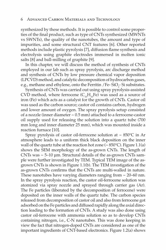
In this chapter, we will discuss the method of synthesis of CNTs employed in our lab such as spray pyrolysis, arc discharge method and synthesis of CNTs by low pressure chemical vapor deposition (LPCVD) method, and catalytic decomposition of hydrocarbon gases, e.g., methane and ethylene, onto the Ferritin /Fe- SiO2- Si substrates.
Synthesis of CNTs was carried out using spray pyrolysis-assisted CVD method, where ferrocene (C10H10Fe) was used as a source of iron (Fe) which acts as a catalyst for the growth of CNTs. Castor oil was used as the carbon source; castor oil contains carbon, hydrogen and lower amount of oxygen. The spray pyrolysis setup consisted of a nozzle (inner diameter ~ 0.5 mm) attached to a ferrocene-castor oil supply used for releasing the solution into a quartz tube (700 mm long and inner diameter 25 mm), which was mounted inside a reaction furnace [10].
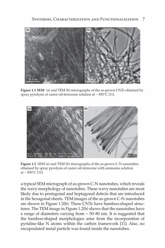
Spray pyrolysis of castor oil-ferrocene solution at ~ 850°C in Ar atmosphere leads to a uniform thick black deposition on the inner wall of the quartz tube at the reaction hot zone (~ 850°C). Figure 1.1(a) shows the SEM morphology of the as-grown CNTs. The length of CNTs was ~ 5–10 μm. Structural details of the as-grown CNTs sam-ple were further investigated by TEM. Typical TEM image of the as-grown CNTs is shown in Figure 1.1(b). The TEM investigation of the as-grown CNTs confi rms that the CNTs are multi-walled in nature. These nanotubes have varying diameters ranging from ~ 20–60 nm. In the spray pyrolysis reaction, the castor oil-ferrocene solution was atomized via spray nozzle and sprayed through carrier gas (Ar). The Fe particles (liberated by the decomposition of ferrocene) were deposited on the inner walls of the quartz tube. The carbon species released from decomposition of castor oil and also from ferrocene got adsorbed on the Fe particles and diffused rapidly along the axial direc-tion leading to the formation of CNTs. A study was also done using castor oil-ferrocene with ammonia solution so as to develop CNTs containing nitrogen, i.e., C-N nanotubes. This was done keeping in view the fact that nitrogen-doped CNTs are considered as one of the important ingredients of CNT-based electronics. Figure 1.2(a) shows
Synthesis, Characterization and Functionalization 7
a typical SEM micrograph of as-grown C-N nanotubes, which reveals the wavy morphology of nanotubes. These wavy nanotubes are most likely due to pentagonal and heptagonal defects that are introduced in the hexagonal sheets. TEM images of the as-grown C-N nanotubes are shown in Figure 1.2(b). These CNTs have bamboo-shaped struc-tures. The TEM image in Figure 1.2(b) shows that the nanotubes have a range of diameters varying from ~ 50–80 nm. It is suggested that the bamboo-shaped morphologies arise from the incorporation of pyridine-like N atoms within the carbon framework [11]. Also, no encapsulated metal particle was found inside the nanotubes.
(a) (b)
Figure 1.1 SEM (a) and TEM (b) micrographs of the as-grown CNTs obtained by spray pyrolysis of castor oil-ferrocene solution at ~ 850°C [11].
(a) (b)
Figure 1.2 SEM (a) and TEM (b) micrographs of the as-grown C-N nanotubes
obtained by spray pyrolysis of castor oil-ferrocene with ammonia solution
at ~ 850°C [11].

8 Advanced Carbon Materials and Technology
Another method used is arc discharge method where SWNTs webs have been synthesized using Fe as catalysts by this method in argon atmosphere. SWNTs has been synthesized by using elec-tric arc discharge of graphite cathode (3cm×1cm×1cm) and Fe as well as Ni-Y fi lled anode (5cm×0.8cm×0.8) at 200 torr pressure of argon gas. The SWNTs webs have been synthesized using Fe as catalysts by arc discharge method in argon atmosphere. Figure 1.3 shows the low magnifi cation SEM micrographs of as-synthesized SWNTs web. The inset of Figure 1.3(a) shows the optical photo-graph of the as-deposited web on the chamber walls. The length of these webs is around 4 to 6 cm. The webs are ~75 to 100 μm thick, which abundantly contains the SWNTs, as is clear from Figure 1.3(b). Figure 1.3(c) shows the SEM image from the inner region between the two webs, dominantly containing SWNTs. A few SWNTs are also visible in Figure 1.3(d), which are coming out from these bundles.
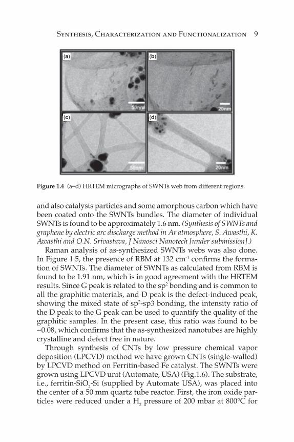
Figure 1.4 shows the transmission electron micrographs of SWNTs bundles. Figure 1.4(a) reveals the bundles containing large amount of SWNTs along with the catalyst particle which have been used to synthesize these SWNTs. Figure 1.4(b) shows the HRTEM image of as synthesized SWNTs as shown in Figure 1.4(a). Figure 1.4(c,d) are from the different regions of the samples containing SWNTs bundles
(a) (b)
(d)(c)
Figure 1.3 (a–d) SEM micrographs of as synthesized SWNTs webs, Inset of Fig. 1.3(a) shows the optical photograph of SWNTs web, some SWNTs which are coming out of the bundle.
Synthesis, Characterization and Functionalization 9
and also catalysts particles and some amorphous carbon which have been coated onto the SWNTs bundles. The diameter of individual SWNTs is found to be approximately 1.6 nm. (Synthesis of SWNTs and graphene by electric arc discharge method in Ar atmosphere, S. Awasthi, K. Awasthi and O.N. Srivastava, J Nanosci Nanotech [under submission].)
Raman analysis of as-synthesized SWNTs webs was also done. In Figure 1.5, the presence of RBM at 132 cm-1 confi rms the forma-tion of SWNTs. The diameter of SWNTs as calculated from RBM is found to be 1.91 nm, which is in good agreement with the HRTEM results. Since G peak is related to the sp2 bonding and is common to all the graphitic materials, and D peak is the defect-induced peak, showing the mixed state of sp2-sp3 bonding, the intensity ratio of the D peak to the G peak can be used to quantify the quality of the graphitic samples. In the present case, this ratio was found to be ~0.08, which confi rms that the as-synthesized nanotubes are highly crystalline and defect free in nature.
Through synthesis of CNTs by low pressure chemical vapor deposition (LPCVD) method we have grown CNTs (single-walled) by LPCVD method on Ferritin-based Fe catalyst. The SWNTs were grown using LPCVD unit (Automate, USA) (Fig.1.6). The substrate, i.e., ferritin-SiO2-Si (supplied by Automate USA), was placed into the center of a 50 mm quartz tube reactor. First, the iron oxide par-ticles were reduced under a H2 pressure of 200 mbar at 800°C for
(a) (b)
(c) (d)
Figure 1.4 (a–d) HRTEM micrographs of SWNTs web from different regions.

10 Advanced Carbon Materials and Technology
10 min. CNTs growth was then performed on the substrate at 800°C for 15 and 30 min under fl ows of 1400 sccm of methane, 100 sccm of ethylene and 500 sccm of H2. After CVD reaction, the furnace was switched off and allowed to cool down to room temperature under Ar gas fl ow of 500 sccm. (Synthesis of SWNTs and graphene by electric arc discharge method in Ar atmosphere, S. Awasthi, K. Awasthi and O.N. Srivastava, J Nanosci Nanotech [under submission].)
G peak
132
cm–1
1332
cm
–1
1575
cm
–1
2655
cm
–1
D peak
0 500 1000 1500
Raman shift cm–1
2000 2500 3000
Inte
nsi
ty (
a.u
.)
2D peak
RBM
Figure 1.5 Raman spectrum of as-synthesized SWNTs webs.
~0.5–2 μmLength of CNTs
~1–6 μm~0.5–2 μm ~0.5–8 μm
Figure 1.6 SEM images of as-grown CNTs using ferritin-SiO2-Si substrate at different temperatures.

Synthesis, Characterization and Functionalization 11
1.3 Synthesis and Characterization of Graphene
Graphite is stacked layers of many graphene sheets, bonded together by week van der Waals force. Thus, in principle, it is possi-ble to produce graphene from a high purity graphite sheet, if these bonds can be broken. Exfoliation and cleavage use mechanical and chemical energy, respectively, for breaking these weak bonds and separate out individual graphene sheets. To scale up the produc-tion, various synthetic methods are being developed. Some of the methods listed are presented below.
1.3.1 Micromechanical Cleavage of Highly Oriented Pyrolytic Graphite
The remarkably simple yet effi cient method developed by Novoselov and Geim consists in using common adhesive tape to repeat the stick and peel process a dozen times which statistically brings a 1mm-thick graphite fl ake to a monolayer thin sample. The fi rst piece of graphene sheet was obtained via manual mechanical cleavage of graphite with a Scotch tape [12], which seems to break the rule that no 2D crystals can exist under ambient conditions and shows us many unusual properties [12]. The exfoliated graphene manifests a unique structure and superior properties, although this production method is not applicable on a large scale. Inspired by this pioneering work, several alternative techniques have been developed for fabricating graphene materials.
Graphene has been made by four different methods. This approach, which is also known as the “Scotch tape” or peel-off method, was based on earlier work on micromechanical exfolia-tion from patterned graphite [13], and the fourth was the creation of colloidal suspensions. Micromechanical exfoliation has yielded small samples of graphene that are useful for fundamental study, although large-area graphene fi lms (up to ~1cm2) of single- to few-layer graphene have been generated by CVD growth on metal.
1.3.2 Chemical Vapor Deposition Growth of Graphene either as Stand Alone or on Substrate
Another feasible method is by chemical vapor deposition (CVD) and epitaxial growth, such as decomposition of ethylene on nickel

12 Advanced Carbon Materials and Technology
surfaces [14]. These early efforts (which started in 1970) were fol-lowed by a large body of work by the surface-science community on “monolayer graphite” [15]. Epitaxial growth on electrically insu-lating surfaces such as SiC has also been used for the growth of gra-phene [16, 17]. One of the highly popular techniques of graphene growth is thermal decomposition of Si on the (0001) surface plane of single crystal of 6H-SiC [18]. Graphene sheets are found to be formed when H2-etched surface of 6H-SiC was heated to tempera-tures of 1250 to 14500°C for a short time (1–20 minutes). Graphene epitaxially grown on this surface typically has 1 to 3 graphene lay-ers; the number of layers being dependent on the decomposition temperature. In a similar process, Rollings et al. have produced gra-phene fi lms as low as one atom thick [19]. The fi rst report on planar few-layer graphene (PFLG) synthesized by CVD was in 2006 [20]. In this work, a natural, eco-friendly, low-cost precursor, camphor, was used to synthesize graphene on Ni foils. Camphor was fi rst evaporated at 1800°C and then pyrolyzed in another chamber of the CVD furnace at 700 to 850°C using argon as the carrier gas. Large-area, high quality graphene can also be grown by thermal CVD on catalytic transition metal surfaces such as nickel and cop-per [21, 22]. Reina et al. prepared single- to few-layer graphene on polycrystalline Ni fi lm of 1-2 cm2 [23]. The Ni fi lm (500 nm thick) was evaporated on a SiO2/Si substrate and was annealed in Ar+H2 atmosphere at 900 to 10000°C, for 10 to 20 minutes. This annealing step created Ni grains of 5 to 20 μm in size. After CVD at 900 to 10000°C for 5 to 10 minutes, using 5 to 25 sccm CH4 and 1500 sccm H2, graphene was found to form on the Ni—the size of each gra-phene being restricted by the Ni grain size. For Ni, mixed mono- and bi-layer graphene coverage of 87% has been reported [24, 25], while for Cu foils, an average of 95% of surfaces were covered by mono-layer graphene [26]. The graphene was later transferred to any substrate, keeping its electrical properties unchanged, thus making them suitable for various electronic applications. Typical CVD graphene growth uses gaseous hydrocarbons at elevated tem-peratures as the carbon source, such as methane, ethylene [27–29] and acetylene [3]. Single-layer graphene were synthesized from ethanol on Ni foils in an Ar atmosphere under atmospheric pres-sure by fl ash cooling after CVD, but a wide variation in graphene layer number was observed over the metal surface [31]. Single- and few-layer graphene fi lms were grown employing a vacuum-assisted CVD technique on Cu foils using n-hexane as a liquid
Synthesis, Characterization and Functionalization 13
precursor [32]. Copper appears to have a small affi nity for oxygen that allows for graphene growth even if the source of carbon is a solid, such as the sugar as reported recently [33]. Graphene, thus synthesized and transferred onto a glass substrate, has shown 90% optical transmittance [34].
1.3.3 Chemical and Thermal Exfoliation of Graphite Oxide
Some recent success in regards to graphene includes chemical exfoliation through the formation of derivatized graphene sheets such as GO [35, 36], r-GO [37], or halogenated graphene, solvent-assisted ultrasonic exfoliation [38]. Graphite oxide was fi rst pre-pared in the nineteenth century [39], and since then it has been mainly produced by the following methods pronounced by Brodie, Staudenmaier [40] and Hummers [41]. All three methods involve oxidation of graphite in the presence of strong acids and oxidants. The level of the oxidation can be varied on the basis of the method, the reaction conditions and the precursor graphite used. Although extensive research has been done to reveal the chemical structure of graphite oxide, several models are still being worked out. Graphite oxide consists of a layered structure of “graphene oxide” sheets that are strongly hydrophilic such that intercalation of water mole-cules between the layers readily occurs [42]. The interlayer distance between the graphene oxide sheets increases reversibly from 6 to 12 Å with increasing relative humidity [43]. Notably, graphite oxide can be completely exfoliated to produce aqueous colloidal suspen-sions of graphene oxide sheets by simple sonication [44] and by stirring the water/graphite oxide mixture for a long enough time [45]. The second approach is the oxidation-exfoliation-reduction of graphite powder [46]. Severe oxidation treatment converts graphite to hydrophilic graphite oxide which can be exfoliated into single-layer graphite oxide (graphene oxide) via stirring or mild sonica-tion in water. Graphene oxide can be regarded as a functionalized graphene containing hydroxyl, epoxy and carboxylic groups, pro-viding reaction sites for chemical modifi cations [47]. Reducing graphene oxide can partly restore its graphitic structure as well as conductivity [48]. Although reduced graphene oxide (r-GO), (also called chemically modifi ed graphene [CMG], chemically converted graphene [CCG] or graphene), has considerable defects, it is one of the most widely used graphene-based renewable energy materials

14 Advanced Carbon Materials and Technology
due to its low cost, facile preparation process, large productivity, and potential for functionalization [49].
1.3.4 Arc-Discharge Method
The arc-discharge method has also been used to prepare graphene sheets. Rao et al. reported for the fi rst time that the arc-discharge method can also be used for the synthesis of graphene sheets [50]. By using graphite rods as electrodes, they have synthesized pure graphene with mainly 2–4 layers in the inner wall region of the arc chamber under relatively high pressure of hydrogen without any catalyst. Moreover, through this method, nitrogen-doped and boron-doped graphene sheets can also be easily synthesized with boron sources (B2H6) or nitrogen sources (pyridine) mixed into the hydrogen gas. However, the size and thickness of the pure graphene sheets still have room to improve, and the properties of the N- and B-doped graphene sheets synthesized also need further studies.
1.4 Methods Used in Our Lab: CVD, Thermal Exfoliation, Arc Discharge and Chemical Reduction
To scale up the production, various synthetic methods are being developed. One of the methods is micromechanical cleavage of highly oriented pyrolytic graphite, however, the yield is very low. Another feasible method is by chemical vapor deposition (CVD) and epitaxial growth, chemical and thermal exfoliation of graphite oxide. Graphite oxide was fi rst prepared in the nineteenth century [51], and since then it has been mainly produced by the following methods pronounced by Brodie, Staudenmaier and Hummers. All three methods involve oxidation of graphite in the presence of strong acids and oxidants. Graphite oxide consists of graphene sheets dec-orated mostly with epoxide and hydroxyl groups. Graphite oxide resulting from the deployment of these methods when subjected to thermal exfoliation leads to the formation of graphene oxide, and that method is called thermal exfoliation. Here the dried graphite oxide powder (~ 200 m) was placed in a quartz tube (diameter ~ 25 mm and length ~ 1.3 m). The sample was fl ushed with Ar for 15 min and the quartz tube was quickly inserted into a furnace preheated

Synthesis, Characterization and Functionalization 15
to 1050°C and held in the furnace for 30 s. The as-prepared GO was a brownish powder while the exfoliated version was of light consis-tency and shiny black. The XRD pattern of graphite, graphite oxide and graphene are shown in Figure 1.7. The XRD pattern of graph-ite shows an intense peak 2θ = 26.4°. This peak corresponds to 002 plane of graphite with interlayer spacing of 0.34 nm. In the XRD pattern of graphite oxide a new peak appears at 2θ = 13.2°, cor-responding to the 002 plane of graphite oxide [52]. The interlayer spacing of GO is ~ 0.75 nm, which is signifi cantly larger than that of graphite, due to intercalating oxide functional groups. The mecha-nism of exfoliation is mainly the expansion of CO2 evolved into the interstices between the graphene sheets during rapid heating. The disappearance of native graphite XRD peaks in the XRD pattern of as-prepared graphene sample supports the formation of graphene sheets.
Few-layer graphene (FLG) has been synthesized by using electric-arc discharge of graphite electrodes in argon ambience at different pressure. The arc was maintained by continuously trans-lating the anode to keep a constant distance of ~1 mm from the cathode. The deposits collected from the inner walls of the arc chamber have been characterized and Figure 1.8(a,b) shows the TEM images of as-synthesized FLG at 350 torr pressure of argon. Distinct features of the micrographs are the large-area graphene sheet-like structures as can clearly be seen in the Figure 1.8. Few-layer graphene nanosheets are clearly visible in the images. The
GrapheneIn
ten
sity
(a.
u.)
Graphite oxide
Graphite
(002
)
(002
)
5 10 15 20 25 30 35
2θθ ( degree )
Figure 1.7 The XRD patterns of graphite, graphite oxide and graphene samples.

16 Advanced Carbon Materials and Technology
Figure 1.8(b) shows the HRTEM image of the large-area graphene with minimum number of layers equal to four. The width of these graphene nanosheets is ~100-200 nm.
1.4.1 Raman Spectra
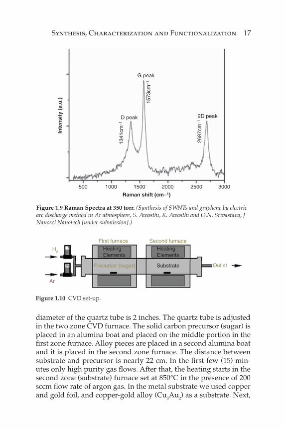
It is worth mentioning that an extensive analysis of graphene has been reported by Ferrari et al. [53], who have demonstrated that the second order Raman peak centered at 2700 cm−1 (2D peak) is the characteristic graphene feature and can be very useful in identify-ing the number of layers in a few-layer graphene sample. The num-ber of layers in a graphene fi lm can be estimated from the intensity, shape and position of the G and 2D bands. While the 2D band changes its shape, width and position with an increasing number of layers, the G-band peak position shows a down-shift with the num-ber of layers. From XRD and TEM analysis it has been found that at 350 torr the minimum numbers of graphene layer are formed. By monitoring the width and position of this 2D peak one can deduce the number of layers from graphene samples. In Figure 1.9 at 350 torr, the 2D peak is at 2687cm-1, confi rming the formation of FLG.
Synthesis of large-area, high-quality and uniform graphene fi lms on metal substrate by chemical vapor deposition (CVD) is shown in Figure 1.10. Chemical vapor deposition (CVD) is one of the main interesting synthetic procedures because it employs hydrocarbon decomposition over substrates, where metal nanoparticles have been placed. A one meter long quartz tube is used in the CVD system in our laboratory. The CVD system has a two zone furnace and the
(a) (b)
Figure 1.8 TEM micrographs of as-synthesized graphene nanosheets at 350 torr argon pressure.
Synthesis, Characterization and Functionalization 17
G peak
D peak
500 1000 1500 2000 2500 3000
1341
cm–1
1573
cm–1
2687
cm–1
2D peak
Inte
nsi
ty (
a.u
.)
Raman shift (cm–1)
Figure 1.9 Raman Spectra at 350 torr. (Synthesis of SWNTs and graphene by electric arc discharge method in Ar atmosphere, S. Awasthi, K. Awasthi and O.N. Srivastava, J Nanosci Nanotech [under submission].)
First furnace
Precursor (sugar) Outlet
H2
Second furnace
Ar
HeatingElements
HeatingElements
Substrate
Figure 1.10 CVD set-up.
diameter of the quartz tube is 2 inches. The quartz tube is adjusted in the two zone CVD furnace. The solid carbon precursor (sugar) is placed in an alumina boat and placed on the middle portion in the fi rst zone furnace. Alloy pieces are placed in a second alumina boat and it is placed in the second zone furnace. The distance between substrate and precursor is nearly 22 cm. In the fi rst few (15) min-utes only high purity gas fl ows. After that, the heating starts in the second zone (substrate) furnace set at 850°C in the presence of 200 sccm fl ow rate of argon gas. In the metal substrate we used copper and gold foil, and copper-gold alloy (Cu3Au2) as a substrate. Next,
18 Advanced Carbon Materials and Technology
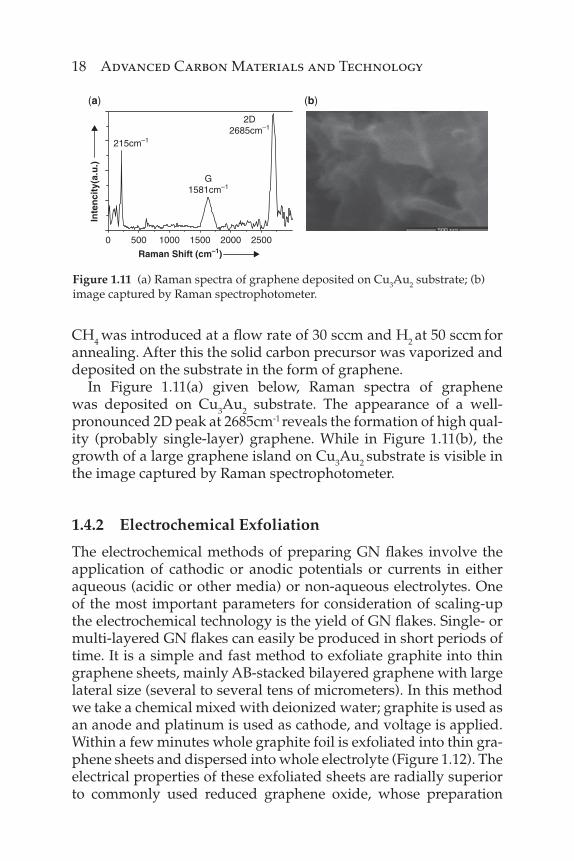
CH4 was introduced at a fl ow rate of 30 sccm and H2 at 50 sccm for annealing. After this the solid carbon precursor was vaporized and deposited on the substrate in the form of graphene.
In Figure 1.11(a) given below, Raman spectra of graphene was deposited on Cu3Au2 substrate. The appearance of a well- pronounced 2D peak at 2685cm-1 reveals the formation of high qual-ity (probably single-layer) graphene. While in Figure 1.11(b), the growth of a large graphene island on Cu3Au2 substrate is visible in the image captured by Raman spectrophotometer.
1.4.2 Electrochemical Exfoliation
The electrochemical methods of preparing GN fl akes involve the application of cathodic or anodic potentials or currents in either aqueous (acidic or other media) or non-aqueous electrolytes. One of the most important parameters for consideration of scaling-up the electrochemical technology is the yield of GN fl akes. Single- or multi-layered GN fl akes can easily be produced in short periods of time. It is a simple and fast method to exfoliate graphite into thin graphene sheets, mainly AB-stacked bilayered graphene with large lateral size (several to several tens of micrometers). In this method we take a chemical mixed with deionized water; graphite is used as an anode and platinum is used as cathode, and voltage is applied. Within a few minutes whole graphite foil is exfoliated into thin gra-phene sheets and dispersed into whole electrolyte (Figure 1.12). The electrical properties of these exfoliated sheets are radially superior to commonly used reduced graphene oxide, whose preparation
0 500
215cm–1
G1581cm–1
2D2685cm–1
2500200015001000
Raman Shift (cm–1)
Inte
nci
ty(a
.u.)
(a) (b)
Figure 1.11 (a) Raman spectra of graphene deposited on Cu3Au2 substrate; (b) image captured by Raman spectrophotometer.

Synthesis, Characterization and Functionalization 19
typically requires many steps including oxidation of graphite and high temperature reduction.
1.5 Functionalization of Carbon Nanotubes and Graphene
Beyond synthesis by different techniques, it appears immediately clear that CNTs and graphene need processing after their syn-thesis. To address this issue, purifi cation methods and, above all, functionalization approaches, are essential to allow manipulation and further application of this material. Usually, metal nanopar-ticles and amorphous carbon are present as a synthetic residue. In general, these carbon nanomaterials are a fl uffy powder diffi cult to manage, while chemical functionalization contributes to the preparation of more homogenous and soluble material. SWNTs are highly polarizable smooth-sided carbon compounds with attrac-tive interaction of 0.5 eV per nanometer of inter-tube contact. This extreme cohesive force makes it diffi cult to disperse SWNTs into individual state. Pristine SWNTs tend to agglomerate in the poly-mer matrix and form bundles. Similarly, pristine graphene is also hydrophobic, so producing stable suspension of graphene in water or organic solvents is an important issue for the fabrication of many graphene-based devices [54, 55]. Prevention of aggregation was of
(a) (b)
Figure 1.12 A set up in our lab showing (a) before exfoliation; (b) after exfoliation.

20 Advanced Carbon Materials and Technology
particular importance for graphene sheets because most of their unique properties were only associated with individual sheets and keeping them well separated was required. Strategies for function-alizing these carbon nanomaterials are important for the pursuit of these applications so these materials should be dispersed uni-formly and form stable suspension. In recent years, new function-alization methods have been developed to disperse these carbon nanomaterials which allow their application [56, 57] A wide variety of functionalizations have been reported in the literature [58–60], the most important of which are summarized in Scheme 1.1. We can categorize mainly covalent and non-covalent approaches.
1.5.1 Covalent Functionalization
In this method CNTs are functionalized by nonreversible attach-ment of appendage on the sidewalls and/or on the tips. Also in this case, many different approaches are reported [13]. Briefl y, reactions can be performed at the sidewall site (sidewall functionalization) or at the defect sites (defect functionalization), usually localized on the tips. In the fi rst case, fl uorination with elemental fl uorine at high temperature (400–600°C) has been explored, accomplishing further substitutions with alkyl groups. Furthermore, radical addition via diazonium salt has been proposed by Tour’s group [62]. On the other hand, cycloadditions have found wide interest. Cycloadditions
Non-covalent functionalization Defect functionalization
CNTs
Endohedral functionalization
π-stacking Sidew all functionalization
Scheme 1.1 A wide variety of functionalizations adapted from ref. [61].
Synthesis, Characterization and Functionalization 21
have been reported, such as carbene [2+1] cycloadditions or Diels-Alder via microwave (MW) irradiation cycloaddition. Side defects functionalization occurs via amidation or esterifi cation reactions of carboxylic residues obtained on CNTs. Moreover, it is feasible that in general caps (i.e., tips when they are not cut) are more reactive than sidewalls because of their mixed pentagonal-hexagonal struc-ture. The f-MWCNTs are not modifi ed in their electronic structure and new properties can be added by means of functionalization. Instead, electronic properties of SWCNTs are perturbed by covalent functionalization and double bonds are irreversibly lost. This may affect conductive property, preventing further CNT applications.
1.5.2 Non-Covalent Functionalization
Recently, non-covalent functionalization has been preferred as it has several advantages over covalent functionalization. Noncovalent functionalization preserves the structural and electrical properties of CNTs and graphene which may be advantageous for future appli-cation. Noncovalent functionalization of these carbon nanonmateri-als is basically through van der Waals, electrostatic and π-stacking interaction, etc. [63]. CNTs wrapping by polymers, including DNA, have been studied [64]; also, proteins are able to non-convalently interact with CNTs and these are often used for biosensor applica-tions [65]. Furthermore, these procedures are usually quite simple and quick, and involve simple steps like ultrasonication, fi ltera-tion, magnetic stirring and centrifugation, etc., and also do not perturb the electronic structure of CNTs, graphene and SWCNTs in particular.
These functionalization methods generally involve the conjuga-tion of these carbon nanomaterials with the biological species like protein, carbohydrates and nucleic acid, etc.
In our lab we have functionalized CNT and graphene both by covalent and non-covalent methods. Covalent functionalization with amine groups of CNTs was achieved after such steps as car-boxylation, acylation and amidation [66]. These CNTs were treated with a concentrated H2SO4/HNO3 mixture to form a stable aque-ous suspension containing individual oxidized CNTs with carboxyl groups (Figure 1.13). Then carboxylated CNTs were treated with ethylenediamine [NH2(CH2)2NH2], forming an active amine group on the nanotubes surface. The optical image of as-synthesized CNTs and amino-functionalized CNTs is also shown in Figure 1.14(a).

22 Advanced Carbon Materials and Technology
H2SO4:HNO3(3:1)
2HN(CH
2)2HN
NH(CH2)2NH
2
NH(CH2)2NH
2
SOCI2
Sonication(8h) &stirring (10h)at 100° C
CNT withcarboxylicgroup
EDA
O
OHHO
C
CO
ClCl
Cl
C
C
CO
O
C
O
C
O
O
O
Magnetic stirring(48h) at room temp.
Magnetic stirring(30h) at room temp.
SOCl2: Thionyl chloride
EDA: Ethylenediamine (H2NCH2CH2NH2)
CNT with amine group
C
OH
C
O
Figure 1.13 Schematic of the reaction scheme to form carbon nanotube (CNT) with amino functionalization [66].
(a) (b)
Figure 1.14 (a) As synthesized CNTs; (b) Amino functionalized CNTs.
Several reports are available for functionalizing graphene and CNTs by biomolecules. The biological molecules which possess hydrophobic and hydrophilic moieties provide a more effi cient means to solubilize the nanomaterial in water than the use of sur-factants and polymers. Molecules containing aromatic groups or

Synthesis, Characterization and Functionalization 23
electron-rich environments have also been reported to modify nano-tubes/nanosheets via -π stacking. The non-covalent approaches are based on interactions of the hydrophobic part of the adsorbed mol-ecules with nanotube sidewalls through van der Waals, -π, CH-, and other interactions, and aqueous solubility is provided by the hydrophilic part of the molecules. If any, the charging of the nano-tube surface by adsorbed ionic molecules additionally prevents nanotube aggregation by the coulombic repulsion forces between modifi ed CNTs. In the last few years, the non-covalent treatment of CNTs with surfactants and polymers has been widely used in the preparation. On the basis of these observations, we explored the use of a novel amino-acid-based non-covalent functionalization of graphene and CNTs using amino acid L-cysteine.
Purifi ed CNTs and graphene were dispersed in double distilled water and sonicated for one hour at room temperature for CNTs and one and a half hours for graphene to obtain homogeneous solu-tion. Then, 0.1 M of L-cysteine was added and sonicated for 30 min followed by 2 h for CNTs and 3 h for graphene of constant stirring to each solution. The CNTs and graphene so obtained were thor-oughly washed with double-distilled water in centrifuge at 10,000 rpm for 10 min and the solution phase was discarded. This washing was repeated fi ve times in order to remove any unbound L-cysteine.
1.5.3 FTIR Analysis of CNTs and FCNTs
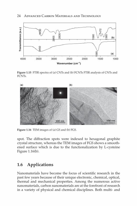
The presence of functional groups after the functionalization of CNTs and functionalized CNTs by FTIR spectroscopy are shown in Figure 1.15. Figure 1.15(a) shows the FTIR spectra of purifi ed CNTs, the band at 3450cm-1 is attributed to the presence of –OH group on the surface of CNTs and is believed to be due to the oxidation during the purifi cation of nanotubes. The peak present at 1585 cm-1 corresponds to the C=C stretching vibration of CNTs. In the FTIR spectra of amino FCNTs, Figure 1.15(b), the peak at 3430 cm-1 is due to the NH2 stretch of the amine group overlapped with –OH stretching vibration. The presence of peaks at 1472 and 1385cm-1 correspond to the N-H and C-N bond stretching of amine group, respectively. The peaks at 2955 and 2835 cm-1 are due to the –CH stretching of CH2 group.
The TEM image of GS reveals a wrinkled paper-like structure (Figure 1.16a). The inset in Figure 1.16(a) is the selected area elec-tron diffraction pattern (SAED) of GS, showing a clear diffraction
24 Advanced Carbon Materials and Technology
spot. The diffraction spots were indexed to hexagonal graphite crystal structure, whereas the TEM images of FGS shows a smooth-ened surface which is due to the functionalization by L-cysteine Figure 1.16(b).
1.6 Applications
Nanomaterials have become the focus of scientifi c research in the past few years because of their unique electronic, chemical, optical, thermal and mechanical properties. Among the numerous active nanomaterials, carbon nanomaterials are at the forefront of research in a variety of physical and chemical disciplines. Both multi- and
4000 3500 3000 2500 2000 1500 1000
(a)
Tra
nsm
itta
nce
(a.
u.)
Wavenumber (cm–1)
1585
3450
(b)
1385
1472
1580
2835
2955
3430
Figure 1.15 FTIR spectra of (a) CNTs and (b) FCNTs FTIR analysis of CNTs and FCNTs.
(a) (b)
Figure 1.16 TEM images of (a) GS and (b) FGS.

Synthesis, Characterization and Functionalization 25
single-walled carbon nanotubes and graphene sheets (GS) show great promise for advancing the fi elds of biology [67], medicine [68], electronics [69], composite material [70], energy technology [71], etc. Currently there is a fl urry of activity amongst scientists to exploit the unique properties of these carbon nanomaterials for potential application. We have also used these carbon nanomaterials for vari-ous applications such as drug delivery, biosensing, protein immo-bilization, protein and DNA immobilization, hydrogen storage, etc. Some of the applications used in our lab are discussed briefl y below.
a) Targeted killing of Leishmania donovani in vivo and in vitro with amphotericin B attached to functionalized car-bon nanotubes and graphene
The development of new drug delivery systems is attractive as it allows optimization of the pharmacological profi le and the thera-peutic properties of existing drugs. Within the family of nanomate-rials, carbon nanotubes and graphene have emerged as a new and effi cient tool for transporting therapeutic molecules, due to their unique physical and chemical properties. By employing the drug delivery system of f-CNTs to the known antileishmanial drug AmB, we found that antileishmanial effi ciency is signifi cantly increased in both in vivo and in vitro settings. This, together with low cyto-toxicity of f-CNT–AmB, means that it is a viable compound for further drug development [72]. The synthesis of f-CNT–AmB was performed on a large scale and it was stored at room temperature for at least six months without any loss of effi cacy.
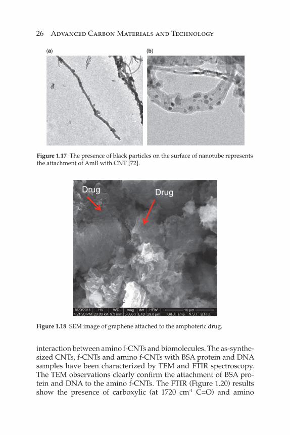
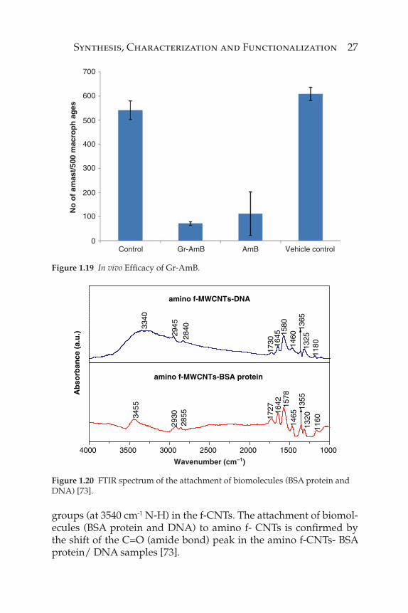
Encouraging in vitro/in vivo results have prompted us to carry out further research on graphene-based drug delivery for Leishmaniasis treatment. The results obtained by targeted drug delivery were more promising as compared to CNT-based drug delivery. The probable reason could be due to the large surface area of graphene enabled to load more drug, thereby improving the bioavailability of drug to the cells. Figure 1.17 below shows the drug-attached gra-phene and Figure 1.18 shows the improved effi cacy of graphene-based drug delivery as compared to CNT.
b) Attachment of biomolecules (protein and DNA) with amino f-CNTs
The biomolecules (e.g., bovine serum albumin [BSA] protein and DNA) have been attached to the multi-walled CNTs through
26 Advanced Carbon Materials and Technology
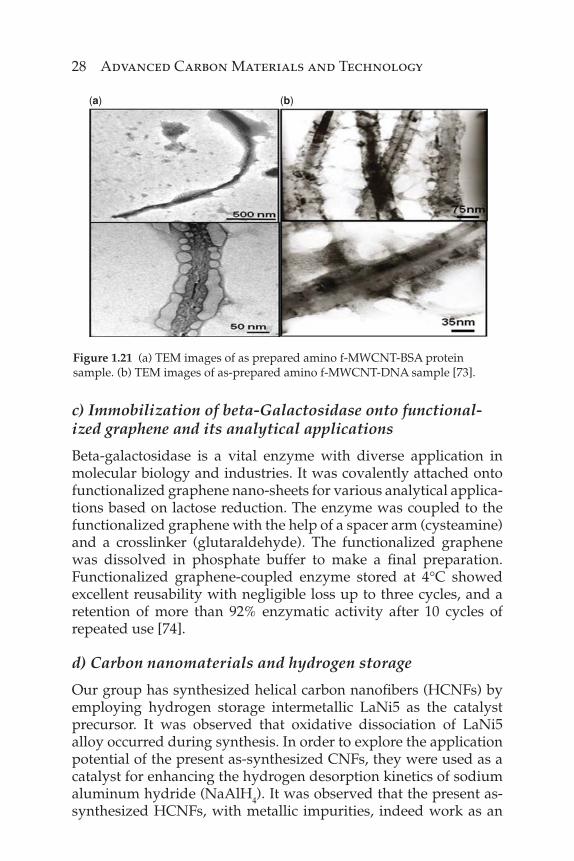
interaction between amino f-CNTs and biomolecules. The as-synthe-sized CNTs, f-CNTs and amino f-CNTs with BSA protein and DNA samples have been characterized by TEM and FTIR spectroscopy. The TEM observations clearly confi rm the attachment of BSA pro-tein and DNA to the amino f-CNTs. The FTIR (Figure 1.20) results show the presence of carboxylic (at 1720 cm-1 C=O) and amino
(a) (b)
Figure 1.17 The presence of black particles on the surface of nanotube represents the attachment of AmB with CNT [72].
DrugDrug
Figure 1.18 SEM image of graphene attached to the amphoteric drug.
Synthesis, Characterization and Functionalization 27
700
600
500
400
300
200
100
0Control Gr-AmB
No
of
amas
t/50
0 m
acro
ph
ag
es
AmB Vehicle control
Figure 1.19 In vivo Effi cacy of Gr-AmB.
4000 3500 3000 2500 2000 1500 1000
3455
Ab
sorb
ance
(a.
u.)
amino f-MWCNTs-BSA protein
1727
2855 16
42 1578
1465
1355
1320
1160
2930
amino f-MWCNTs-DNA
1180
3340
2945
2840
1730 16
45 1580
1460
1365
1325
Wavenumber (cm–1)
Figure 1.20 FTIR spectrum of the attachment of biomolecules (BSA protein and DNA) [73].
groups (at 3540 cm-1 N-H) in the f-CNTs. The attachment of biomol-ecules (BSA protein and DNA) to amino f- CNTs is confi rmed by the shift of the C=O (amide bond) peak in the amino f-CNTs- BSA protein/ DNA samples [73].
28 Advanced Carbon Materials and Technology
c) Immobilization of beta-Galactosidase onto functional-ized graphene and its analytical applications
Beta-galactosidase is a vital enzyme with diverse application in molecular biology and industries. It was covalently attached onto functionalized graphene nano-sheets for various analytical applica-tions based on lactose reduction. The enzyme was coupled to the functionalized graphene with the help of a spacer arm (cysteamine) and a crosslinker (glutaraldehyde). The functionalized graphene was dissolved in phosphate buffer to make a fi nal preparation. Functionalized graphene-coupled enzyme stored at 4°C showed excellent reusability with negligible loss up to three cycles, and a retention of more than 92% enzymatic activity after 10 cycles of repeated use [74].
d) Carbon nanomaterials and hydrogen storage
Our group has synthesized helical carbon nanofi bers (HCNFs) by employing hydrogen storage intermetallic LaNi5 as the catalyst precursor. It was observed that oxidative dissociation of LaNi5 alloy occurred during synthesis. In order to explore the application potential of the present as-synthesized CNFs, they were used as a catalyst for enhancing the hydrogen desorption kinetics of sodium aluminum hydride (NaAlH4). It was observed that the present as-synthesized HCNFs, with metallic impurities, indeed work as an
(a) (b)
Figure 1.21 (a) TEM images of as prepared amino f-MWCNT-BSA protein sample. (b) TEM images of as-prepared amino f-MWCNT-DNA sample [73].

Synthesis, Characterization and Functionalization 29
effective catalyst [75]. Thus there is an enhancement of w5 times in kinetics when as-synthesized HCNFs are used as the catalyst.
1.7 Conclusion
In this chapter we have discussed some of the recent progress in CNT and graphene synthesis and its applications. The research in this area is still in its infancy and much more work is needed to real-ize the technological potential of graphene and CNTs. We should expect many other applications that exploit the unique properties of CNT and graphene to appear in the coming years. Keeping this in view we have synthesized these nanomaterials by applying dif-ferent routes so as to explore and exploit its enormous potential, and also to obtain a high quality material for different applications from drug delivery, energy storage to electronics.
Acknowledgements
The authors are grateful to the Nano Science and Technology Initiative, Department of Science and Technology (DST), India, for fi nancial support. We would also like to thank Prof. C.N.R. Rao and all the lab members who are engaged and contributed in this nano-science research. The fi nancial support from CSIR, and MNRE, New Delhi, are also gratefully acknowledged. M.T. thanks UGC-D.S. Kothari Fellowship for the fi nancial support.
(a) (b)
Figure 1.22 Transmission electron micrograph (TEM) images of functionalized (a) and coupled (b) graphene showing fi ne transparent sheets with insets showing the characteristic Selected-area electron diffraction pattern (SAD). Functionalized graphene sheets appear transparent, whereas islands of immobilized enzyme can be seen in dark shades.

30 Advanced Carbon Materials and Technology
References
1. S. Iijima, and T. Ichihashi, Single-shell carbon nanotubes of 1-nm diameter, Nature, 1993. 363(6430): p. 603–605.3.
2. A.K. Geim, and K.S. Novoselov. The rise of graphene. Nature Mater. 6, 183–191 (2007).
3. S. Iijima, Helical microtubules, Nature 354, 56–58, 1991. 4. D.S. Bethune, et al., Cobalt-catalyzed growth of carbon nanotubes
with single-atomic-layer walls, Nature, 1993. 363(6430): p. 605-607. 5. J. Prasek, J. Drbohlavova, J. Chomoucka, J. Hubalek, O. Jasek, V. Adam,
and R. Kizek. Methods for carbon nanotubes synthesis—review, J. Mater. Chem. 21, 15872–15884, 2011.
6. K. Shen, H. Xu, Y. Jiang, T. Pietraß, The role of carbon nanotube struc-ture in purifi cation and hydrogen adsorption, Carbon 42, 2315-2322, 2004.
7. W.D. Zhang, L. Shen, I.Y. Phang, T. Liu, Surface energy components of a dye-ligand immobilized pHEMA membranes: Effects of their molec-ular attracting forces for non-covalent interactions with IgG and HSA in aqueous media, Macromolecules 37, 256-259, 2004.
8. S. Nakazawa, T. Yokomori, M. Mizomoto, Flame synthesis of carbon nanotubes in a wall stagnation fl ow, Chem. Phys. Lett. 403, 158-162, 2005.
9. X. Lu, M. Yu, H. Huang, and R.S. Ruoff, Tailoring graphite with the goal of achieving single sheets, Nanotechnology 10, 269–272, 1999.
10. A. Srivastava, C. Galande, L. Ci, L. Song, C. Rai, D. Jariwala, et al., Novel liquid precursor-based facile synthesis of large-area continuous, single, and few-layer graphene fi lms, Chem. Mater. 22 (11), 3457–3461, 2010.
11. C.J. Lee, S.C. Lyu, H.W. Kim, J.H. Lee, and K.I. Cho, Chem. Phys. Lett. 359, 115, 2002.
12. K.S. Novoselov, A.K. Geim, S.V. Morozov, D. Jiang, Y. Zhang, S.V. Dubonos, I.V. Grigorieva, and A.A. Firsov, Electric fi eld effect in atom-ically thin carbon fi lms, Science 306, 666-669, 2004.
13. X. Lu, M. Yu, H. Huang, and R.S. Ruoff, Tailoring graphite with the goal of achieving single sheets, Nanotechnology 10, 269–272, 1999.
14. M. Eizenberg and J.M. Blakely. Carbon monolayer phase condensa-tion on Ni(111), Surf. Sci. 82, 228–236, 1970.
15. T. Aizawa, R. Souda, S. Otani, Y. Ishizawa, and C. Oshima, Anomalous bond of monolayer graphite on transition-metal carbide surfaces, Phys. Rev. Lett. 64, 768–771, 1990.
16. C. Berger, Z. Song, X. Li, X. Wu, N. Brown, C. Naud, D. Mayou, T. Li, J. Hass, A.N. Marchenkov, E.H. Conrad, P.N. First, and W.A. Heer, Electronic confi nement and coherence in patterned epitaxial gra-phene, Science 312, 1191–1196, 2006.

Synthesis, Characterization and Functionalization 31
17. K.V. Emtsev, A. Bostwick, K. Horn, J. Jobst, et al., Towards wafer-size graphene layers by atmospheric pressure graphitization of silicon car-bide, Nature Mater. 8, 203–207, 2009.
18. C. Berger, Z. Song, T. Li, X. Li, A.Y. Ogbazghi, R. Feng, Z. Dai, et al., Ultrathin epitaxial graphite: 2D electron gas properties and a route toward graphene-based nanoelectronics, J. Phys. Chem. B 108 (52), 19912–19916, 2004.
19. E. Rollings, G.H. Gweon, S.Y. Zhou, B.S. Mun, J.L. McChesney, B.S. Hussain, A.V. Fedorov, et al., Sythesis and characterization of atomically-thin graphite fi lms on a silicon carbide substrate, J. Phys. Chem. Solids 67, 2172-2177, 2006.
20. P.R. Somani, S.P. Somani, and M. Umeno. Planer nanographenes from camphor by CVD, Chemical Physics Letters 430, 56-59, 2006.
21. S. Bae, H. Kim, Y. Lee, X. Xu, J.-S. Park, Y. Zheng, et al., Roll-to-roll production of 30-inch graphene fi lms for transparent electrodes, Nat. Nano. 5(8), 574–578, 2010.
22. Q. Liu, W. Ren, D.W. Wang, Z.G. Chen, S. Pei, B. Liu, F. Li, H. Cong, C. Liu, and H.M. Cheng, In situ assembly of multi-sheeted buckybooks from single-walled carbon nanotubes, ACS Nano 3(3), 707–713, 2009.
23. A. Reina, S. Thiele, X.T. Jia, S. Bhaviripudi, M.S. Dresselhaus, J.A. Schaefer, et al., Growth of large-area single- and bi-layer graphene by controlled carbon precipitation on polycrystalline Ni surfaces, Nano Res. 2(6), 509–516, 2009.
24. A. Reina, X. Jia, J. Ho, D. Nezich, H. Son, V. Bulovic, M.S. Dresselhaus, and J. Kong, Large area, few-layer graphene fi lms on arbitrary sub-strates by chemical vapor deposition chemical vapor deposition, Nano Lett. 9, 30–35, 2009.
25. K.S. Kim, Y. Zhao, H. Jang, S.Y. Lee, J.M. Kim, K.S. Kim, J.H. Ahn, P. Kim, J.Y. Choi, and B.H. Hong, Large-scale pattern growth of gra-phene fi lms for stretchable transparent electrodes, Nature 457, 706-710, 2009
26. X. Li, W. Cai, J. An, S. Kim, et al., Large-area synthesis of high-quality and uniform graphene fi lms on copper foils, Science 324, 1312-1314, 2009.
27. P.W. Sutter, J.I. Flege, E.A. Sutter, Epitaxial graphene on ruthenium, Nat. Mater. 7, 406–411, 2008.
28. H. Ueta, M. Saida, C. Nakai, Y. Yamada, M. Sasaki, S. Yamamoto, Highly oriented monolayer graphite formation on Pt (111) by a super-sonic methane beam, Surf Sci. 560(1–3), 183–190, 2004.
29. J. Coraux, A.T. N’Diaye, C. Busse, T. Michely, Structural coherency of graphene on Ir(111), Nano Lett. 8(2), 565–570, 2008.
30. G. Nandamuri, S. Roumimov, and R. Solanki, Chemical vapor deposi-tion of graphene fi lms. Nanotechnology 21(14), 145604 (1-4), 2010.
31. Y. Miyata, K. Kamon, K. Ohashi, R. Kitaura, M. Yoshimura, H. Shinohara, A simple alcohol-chemical vapor deposition synthesis
32 Advanced Carbon Materials and Technology
of single-layer graphenes using fl ash cooling, Appl. Phys. Lett. 96, 263105–263107, 2010.
32. A. Srivastava, C. Galande, L. Ci, L. Song, C. Rai, D. Jariwala, et al., Novel liquid precursor-based facile synthesis of large-area continuous, single, and few-layer graphene fi lms, Chem. Mater. 22(11), 3457–3461, 2010.
33. Z. Sun, Z. Yan, J. Yao, E. Beitler, Y. Zhu, and J.M. Tour, Growth of gra-phene from solid carbon sources, Nature 468, 549–552, 2010.
34. W. Choi, I. Lahiri, R. Seelaboyina, Y.S. Kang. Synthesis of graphene and its applications: A review, Critical Reviews in Solid State and Materials Sciences, 35(1), 52–71, 2010.
35. M. Hirata, T. Gotou, S. Horiuchi, M. Fujiwara, M. Ohba, Thin-fi lm
particles of graphite oxide high-yield synthesis and fl exibility of the particles, Carbon 42, 2929–2937, 2004.
36. D.A. Dikin, S. Stankovich, E.J. Zimney, R.D. Piner, G.H.B. Dommett, G. Evmenenko, S.T. Nguyen, and R.S. Ruoff, Preparation and charac-terization of graphene oxide paper, Nature 448, 457–460, 2007.
37. V.C. Tung, M.J. Allen, Y. Yang, and R.B. Kaner, High-throughput solu-tion processing of large-scale grapheme, Nature Nanotech 4, 25–29, 2009.
38. Y. Hernandez, et al., High-yield production of graphene by liquid-phase exfoliation of graphite, Nature Nanotechnology 3, 563-568, 2008.
39. B.C. Brodie, Sur le poids atomique du graphite. Ann. Chim. Phys. 59, 466 (1860).
40. L. Staudenmaier, Verfahren zur Darstellung der Graphitsaure. Ber. Deut. Chem. Ges. 31, 1481 (1898).
41. W.S. Hummers and R.E. Offeman, Preparation of graphitic oxide, J. Am. Chem. Soc. 80, 1339–1339, 1958.
42. A. Buchsteiner, A. Lerf, and J. Pieper, Water dynamics in graph-ite oxide investigated with neutron scattering, J. Phys. Chem. B 110, 22328–22338, 2006.
43. A.A. Balandin, S. Ghosh, W. Bao, I. Calizo, D. Teweldebrhan, F. Miao, and C.N. Lau, Superior thermal conductivity of single-layer graphene, Nano Lett. 8, 902–907, 2008.
44. S. Stankovich, D.A. Dikin, R.D. Piner, K.A. Kohlhaas, A. Kleinhammes, et al., Synthesis of graphene-based nanosheets via chemical reduction of exfoliated graphite oxide, Carbon 45, 1558–1565, 2007.
45. I. Jung, et al., Simple approach for high-contrast optical imaging and characterization of graphene-based sheets, Nano Lett. 7, 3569–3575, 2007.
46. S. Park and R.S. Ruoff, Chemical methods for the production of gra-phenes, Nature Nanotechnology 4, 217–224, 2009.
47. D.R. Dreyer, S. Park, C.W. Bielawski, and R.S. Ruoff, The chemistry of graphene oxide, Chem. Soc. Rev. 39, 228–240, 2010.
48. C. Zhu, S. Guo, Y. Fang, and S. Dong, Reducing sugar: New functional molecule for the green synthesis of graphene nanoshests, ACS Nano 4, 2429–2437, 2010.

Synthesis, Characterization and Functionalization 33
49. Y. Sun, Q. Wu, and G. Shi.Graphene based new energy materials, Energy Environ. Sci. 4, 1113–1132, 2011.
50. C.N.R. Rao, A.K. Sood, K.S. Subrahmanyam, A. Govindaraj, Epitaxial graphite: 2D electron gas properties and a route toward graphene-based, Angew. Chem. Int. Ed. 48, 7752–7777, 2009.
51. C. Schafhaeutl, On the combination of carbon with silicon and iron, and other metals, forming the different species of cast iron, steel, and malleable iron, Phil. Mag. 16, 570–590, 1840.
52. H.C. Schniepp, J.L. Li, M.J. McAllister, H. Sai, M.H. Alonso, D.H. Adamson, R.K. Prud’homme, R. Car, D.A. Saville, and I.A. Aksay, Functionalized single graphene sheets derived from splitting graphite oxide, J. Phys. Chem. B, 110 (17), 8535–8539, 2006.
53. A.C. Ferrari, J.C. Meyer, V. Scardaci, C. Casiraghi, M. Lazzeri, F. Mauri, S. Piscanec, D. Jiang, K.S. Novoselov, S. Roth, and A.K. Geim, Raman spec-trum of graphene and graphene layers, Phys. Rev. Lett. 97, 187401, 2006.
54. D. Li, M.B. Müller, S. Gilje, R.B. Kaner, G.G. Wallace, Processable aque-ous dispersion of graphene nanosheets, Nat. Nanotechnol. 2008;3:101–5.
55. Z. Liu, J.T. Robinson, X. Sun, H. Dai, PEGylated nano-graphene oxide for delivery of water insoluble cancer drugs, J. Am. Chem. Soc. 2008;130:10876–7.
56. Y. Lin, S. Taylor, H. Li, K.A.S. Fernando, L. Qu, W. Wang, L. Gu, B. Zhou, and Y.P. Sun, Advances toward bioapplications of carbon nanotubes, J. Mater. Chem. 14(2004), pp. 527–541.
57. A. Carrillo, J.A. Swartz, J.M. Gamba, R.S. Kane, N. Chakrapani, B.Wei, and P.M. Ajayan, Noncovalent functionalization of graphite and car-bon nanotubes with polymer multilayers and gold nanoparticles, Nano Lett. 3(2003), pp.1437–1440.
58. P. Singh, S. Campidelli, S. Giordani, D. Bonifazi, A. Bianco, M. Prato, Organic functionalisation and characterisation of single-walled car-bon nanotubes, Chemical Society Reviews 2009, 38, 2214–2230.
59. A. Hirsch, Functionalization of single-walled carbon nanotubes, Angewandte Chemie - International Edition 2002, 41, 1853–1859.
60. D. Tasis, N. Tagmatarchis, A. Bianco, M. Prato, Chemistry of carbon nanotubes. Chemical Reviews 2006, 106, 1105–1136.
61. A. Hirsch, Functionalization of single-walled carbon nanotubes, Angewandte Chemie-International Edition 41(11), 1853-1859 (2002).
62. B. Price, J. Hudson, J. Tour, Green chemical functionalization of single-walled carbon nanotubes in ionic liquids, Journal of the American Chemical Society 2005, 127, 14867–14870.
63. B. Long, M. Manning, M. Burke, B.N. Szafranek, G. Visimberga, G. Thompson, J.C. Greer, I.M. Povey, J. MacHale, G. Lejosne, D. Neumaier, and A.J. Quinn, Non-covalent functionalization of graphene using self-assembly of alkane-amines, Adv. Funct. Mat. 22(2012), 717–725.
64. D. Tasis, N. Tagmatarchis, A. Bianco, M. Prato, Chemistry of carbon nanotubes, Chemical Reviews 2006, 106, 1105–1136.
34 Advanced Carbon Materials and Technology
65. A. Jorio, G. Dresselhaus, M.S. Dresselhaus (Eds), Carbon Nanotubes: Advanced Topics in the Synthesis, Structure, Properties and Applications; 1st ed.; Springer, 2008.
66. K. Awasthi, D.P. Singh, S.K. Singh, et al., Attachment of biomolecules (protein and DNA) to amino-functionalized carbon nanotubes. New Carbon Materials 2009; 24: 301–6.
67. M. O’Connor, N.K. Sang, A.J. Killard, et al., Mediated amperometric immunosensing using single walled carbon nanotube forests, Analyst, 129(12), pp. 1176–1180, 2004.
68. L. Zhang and T.J. Webster, Nanotechnology and nanomaterials: Promises for improved tissue regeneration, NanoToday, 4(1), pp. 66–80, 2009.
69. J. Robertson, G. Zhong, S. Esconjauregui, C. Zhang, S. Hofmann, Synthesis of carbonnanotubes and graphene for VLSI interconnects, Microelectronic Engineering 107, 2013, 210–218.
70. H.X. Kong, Hybrids of carbon nanotubes and graphene/graphene oxide. Curr. Opin. Solid State Mater. Sci. (2013), http:// dx.doi.org/10.1016/j.cossms.2012.12.002
71. H. Wang, X. Yuan, Y. Wu, H. Huang, X. Peng, G. Zeng, H. Zhong, J. Liang, M.-M. Ren, Graphene-based materials: Fabrication, charac-terization and application for the decontamination of wastewater and wastegas and the hydrogen storage/generation, Advances in Colloid and Interface Science (2013).
72. V.K. Prajapati, K. Awasthi, S. Gautam, T.P. Yadav, M. Rai, O.N. Srivastava, and S. Sundar, Targeted killing of Leishmania donovani in vivo and in vitro with amphot ericin B attached to functionalized carbon nanotubes, J. Antimicrob. Chemother. 66(2011), pp.874–879.
73. K. Awasthi, D.P. Singh, Sunil Singh, D. Dash, and O.N. Srivastava. Attachment of biomolecules (Protein and DNA) to amino-functionalized carbon nanotubes, New Carbon Materials 24(4) Dec. 2009.
74. Immobilization of b-Galactosidase onto Functionalized Graphene Nano-sheets Using Response Surface Methodology and Its Analytical Applications (2012) Kishore D, Talat M, Srivastava ON and Kayastha AM PLoS ONE 7(7) : e40708. doi:10.1371/journal.pone.0040708.
75. Z. Qian, M. Sterlin, L. Hudson, H. Raghubanshi, R.H. Scheicher, B. Pathak, C.M. Araujo, A. Blomqvist, B. Johansson, O.N. Srivastava, and R. Ahuja. Excellent catalytic effects of graphene nanofi bers on hydrogen release of sodium alanate, J. Phys. Chem. C 2012, 116, 10861−10866.