Embed Size (px)
Citation preview

TRIBHUVAN UNIVERSITY
ADVANCED COLLEGE OF ENGINEERING AND MANAGEMENT
Kupondole, Lalitpur
DEPARTMENT OF ELECTRONICS AND COMPUTER
ENGINEERING
FINAL YEAR PROJECT REPORT ON
“NEUROLOGY DIAGNOSIS SYSTEM” [http://ireasoning.sourceforge.net]
In the partial fulfillment of the requirements for the degree of Bachelor’s Degree in Computer Engineering.
Submitted by: Badri Adhikari [email protected] Roll: 16528 Md. Hasan Ansari [email protected] Roll: 16507 Priti Shrestha [email protected] Roll: 16513 Susma Pant [email protected] Roll: 16535
KATHMANDU, NEPAL
March, 2009
i
Certificate
This is to certify that the work carried out by Mr. Badri Adhikari, Mr. Md. Hasan
Ansari, Miss. Priti Shrestha and Miss. Susma Pant for the project entitled “Neurology
Diagnosis System” for the award of the degree of Bachelor of Computer Engineering
of this institute is based upon their authentic work. We have the pleasure in
forwarding their project. The project was carried out under our supervision and all
the materials included as well as the software product is the result of their half year
authentic work-effort.
------------------------------------- Asst. Prof. Dipesh Gautam Electronics and Computer Engineering Department, Institute of Engineering, Pulchowk Campus. (Extrernal Examiner)
------------------------------------- Prof. Dr. Shashidhar Ram Joshi Electronics and Computer Engineering Department, Institute of Engineering, Pulchowk Campus. (Project Supervisor)
------------------------------------- Er. Binod Chandra Shrestha Department of Electronics and Computer Engineering Advanced College of Engineering and Management (Project Coordinator)
------------------------------------- Er. Bikram Lal Shrestha Sr. Software Engineer D2Hawkeye Services Pvt. Ltd. Bishal Nagar, Kathmandu (Project Mentor)
ii
Declaration
The project documented in this report was carried out by four below mentioned final
year undergraduate students as project group members of the Department of
Computer and Electronics Engineering for the partial fulfillment of the requirements
for the Bachelor Degree of Engineering in Computer Engineering. The project’s source
code is available under terms of the GNU General Public License. This report and the
whole software may be freely referred for any kind of constructive engineering
purposes. A copy is left.
---------------------------- Mr. Badri Adhikari ( Project Lead ) ---------------------------- Mr. Md. Hasan Ansari ---------------------------- Miss. Priti Shrestha ---------------------------- Miss. Susma Pant
March, 2009
iii
Acknowledgement
We are indebted to Dr. Niranjan Acharya (M.D. in Neurology) at T.U. Teaching
Hospital for guiding us to develop the system and for helping us to perform the
knowledge engineering task. We are grateful to the team of neurosurgery doctors at the
National Academy of Medical Sciences (BIR Hospital) for helping us to decide the medical
domain to implement our project. We would also like to thank the team of neurology
doctors at Kathmandu Model Hospital for providing us time and for coordinating with us.
We are grateful to Dr. Umesh P. Khanal at D2Hawkeye Services Pvt. Ltd. for initiating
our communication with Dr. Neelam Khadka at the National Academy of Medical
Sciences. We are equally grateful to Dr. Neelam Khadka for his encouragement and his
promise to help us throughout the project development. We also thank him for
providing us a lot of time and initiating our communication with other doctors at
Department of the National Neurosurgical Referral Center of Bir Hospital. We are also
grateful to Prof. Dr. Pawan Kumar Sultania for his suggestions and acceptance of our
request letter to help us during our project development. We are equally grateful to
Prof. Dr. Prakash Bista at NAMS for providing us suggestions regarding the selection
of implementation domain for our project.
We would also like to thank him for introducing us to the practice of medical
diagnosis and the practice of neurologic examinations. We also express our thanks to
Er. Bikram Lal Shrestha at D2Hawkeye Services Pvt. Ltd. for guiding us to complete
the project and providing us suggestions at every phase of the software development
being our mentor. We would also like to thank the college management for providing us
generator facilities for the project development activities during the heavy load shedding
days. It would be impossible to complete to project smoothly had the college not
provided this facility.
iv
Abstract
“Neurology Diagnosis System” is a web-based expert system for diagnosis of
neurologic disorders or the disorders of our nervous system. Health assistants in
remote areas can use the system to diagnose neurologic patients in the absence of
neurologists. They do not need to be neurology expert to diagnose common
neurologic disorders if trained to use this expert system. The project is of immense
importance to provide medical care facilities to rural people. The importance is felt
because medical experts are not readily available in local hospitals and rural areas.
These medical care requirements can be fulfilled to a large extent by the use of expert
system. This claim is made based upon the results that the system shows and also
upon the feedbacks received from various doctors and experts who observed the
system. Concerning the methodology, the basic principle is to encode the knowledge
of the neurology domain in the form of rules and representative cases and use this
knowledge to solve new cases of patients. This knowledge encoding is essentially the
implementation of two artificial reasoning techniques called case-based reasoning
and rule-based reasoning and is ultimately used to assist the diagnosis process. Since
the software uses artificial reasoning techniques it is an artificial intelligence project
that exploits theoretical knowledge in the form of rules and practical experiences in
the form of representative cases. To perform the reasoning, input to be provided is
the clinical examination data along with medical history. The result of performing
rule-base reasoning is a list of probable diseases and the output of case-based
reasoning is a list of cases similar to the one being diagnosed. Important of the two is
the case-based reasoning component that is like a learning machine that keeps
learning as new cases are inserted. The web-based hybrid expert system was built
using the Java programming language by implementing the Spring Web MVC
framework with MySQL as the database system.
Keywords: medical diagnosis system, artificial intelligence, rule-based reasoning,
case-based reasoning, hybrid expert system, neurology, quadriplegia, paraplegia,
nearest neighbor algorithm.
v
List of Figures
Figure 1-1 Health Assistant Using the System .............................................................................. 6
Figure 2-1 Architecture of a Rule Based Expert System ........................................................... 8
Figure 2-2 Case-based Reasoning Life Cycle ................................................................................. 9
Figure 2-3 Integration of Rule-based and Case-based Reasoning ...................................... 10
Figure 2-4 Architecture of a Hybrid Expert System ................................................................. 11
Figure 2-5 Using Spring MVC to Build Web Pages .................................................................... 16
Figure 3-1 SVN Commit Statistics at the SVN Repository ...................................................... 18
Figure 3-2 Meeting duration with Mentor and Doctors .......................................................... 20
Figure 3-3 Gantt Chart Showing Project Phases ........................................................................ 21
Figure 4-1 Neurologist’s Times Used in Hours per year ......................................................... 24
Figure 4-2 Financial Status of Investor Over Years .................................................................. 25
Figure 5-1 System Architecture ........................................................................................................ 27
Figure 5-2 Context Diagram ............................................................................................................... 27
Figure 5-3 UML Use-case Diagram for Health Assistant ......................................................... 28
Figure 5-4 Deployment Diagram ...................................................................................................... 28
Figure 5-5 Entity-Relationship Diagram ....................................................................................... 29
Figure 5-6 Schema Diagram for the System ................................................................................ 30
Figure 5-7 Sequence Diagram for Rule-based Diagnosis ........................................................ 31
Figure 5-8 Sequence Diagram for Case-based Diagnosis ....................................................... 31
Figure 6-1 Decision Tree for Quadriplegia/Paraplegia ........................................................... 34
Figure 7-1 Results at T.U.T.H. O.P.D. ............................................................................................... 38

vi
List of Tables
Table 2-1 Comparison of Integrated Development Environments .................................... 14
Table 2-2 Comparison of Relational Database Management Systems .............................. 15
Table 3-1 Project Phases and Effort Required ............................................................................ 19
Table 3-2 Team Resource and Roles............................................................................................... 19
Table 3-3 Roles and Responsibilities of Team Members ........................................................ 20
Table 3-4 Major Project Milestones ................................................................................................ 21
Table 6-1 Basic Tools Used for Development ............................................................................. 32
Table 6-2 CASE Tools Used for Development ............................................................................. 32
Table 6-3 Artifacts Produced and Their Location ..................................................................... 33
Table 7-1 Testing of the Nearest Neighbor Algorithm ............................................................ 36

vii
List of Abbreviations
ACID Atomic Consistent Isolated Durable
AI Artificial Intelligence
ASF Apache Software Foundation
BSD Berkeley Software Distribution
CASE Computer-Aided Software Engineering
CBA Cost-benefit Analysis
CBR Case-based Reasoning
CDDL Common Development and Distribution License
DBMS Database Management System
EPL Eclipse Public License
GNU GNU's Not Unix
GPL2 General Public License, version 2
GUI Graphical User Interface
HTTP Hypertext Transfer Protocol
I/O input/output
IDE Integrated Development Environment
JDK Java Development Kit
JDT Java Development Tools
JSP JavaServer Pages
MVC Model View Controller
OPD Outpatient Department
PHP Personal Home Page
RBR Rule-based Reasoning
SE Second Edition
SQL Structured Query Language
SROI Social Return on Investment
SRS Software Requirement Specification
SVN Subversion
UI User Interface
UML Unified Modeling Language
URL Uniform Resource Locator
XML Extensible Markup Language

Table of Contents
Certificate ............................................................................................................................................................. i
Declaration ......................................................................................................................................................... ii
Acknowledgement ......................................................................................................................................... iii
Abstract ............................................................................................................................................................... iv
List of Figures .................................................................................................................................................... v
List of Tables ..................................................................................................................................................... vi
List of Abbreviations ................................................................................................................................... vii
1 INTRODUCTION ........................................................................................................................................ 4
1.1 Background ................................................................................................................................................. 4
1.2 Objectives .................................................................................................................................................... 5
1.3 Project Overview ...................................................................................................................................... 5
2 LITERATURE REVIEW ............................................................................................................................. 7
2.1 The Neurology Domain .......................................................................................................................... 7
2.2 Rule-based Reasoning ............................................................................................................................ 8
2.3 Case-based Reasoning ............................................................................................................................ 9
2.4 Hybrid Expert Systems ....................................................................................................................... 10
2.5 Expert systems for Medical Diagnosis .......................................................................................... 12
2.6 Apache Tomcat as Application Server .......................................................................................... 13
2.7 Eclipse as Programming IDE ............................................................................................................ 14
2.8 MySQL as Database System ............................................................................................................... 15
2.9 Spring Web MVC Framework ........................................................................................................... 16
3 PROJECT MANAGEMENT ...................................................................................................................... 18
3.1 Project Configuration and Management ...................................................................................... 18
3.2 Project Workflow and Schedule ...................................................................................................... 19
3.3 Management Plan .................................................................................................................................. 19
3.3.1 Team ................................................................................................................................................. 19
3.3.2 Roles and Responsibilities ....................................................................................................... 20
3.4 Project Meetings .................................................................................................................................... 20
3.5 Project Activities and Milestones ................................................................................................... 21
3.6 Gantt Chart ............................................................................................................................................... 21

4 SYSTEM ANALYSIS ................................................................................................................................. 22
4.1 Requirement Specification ................................................................................................................ 22
4.1.1 Functional Requirements ......................................................................................................... 22
4.1.2 Nonfunctional Requirements ................................................................................................. 23
4.2 Cost-Benefit Analysis ........................................................................................................................... 24
4.3 Feasibility Assessment ........................................................................................................................ 25
4.3.1 Operational Feasibility .............................................................................................................. 25
4.3.2 Technical Feasibility ................................................................................................................... 26
4.3.3 Economic Feasibility .................................................................................................................. 26
5 HIGH LEVEL DESIGN AND DETAILED DESIGN .............................................................................. 27
5.1 High Level Design .................................................................................................................................. 27
5.1.1 System architecture .................................................................................................................... 27
5.1.2 Context Diagram .......................................................................................................................... 27
5.1.3 UML Use Case Diagram ............................................................................................................. 28
5.1.4 Deployment diagram .................................................................................................................. 28
5.1.5 Entity-Relationship Diagram .................................................................................................. 29
5.2 Detail Design Specifications .............................................................................................................. 30
5.2.1 Database Schema Diagram ...................................................................................................... 30
5.2.2 Sequence Diagrams ..................................................................................................................... 31
6 IMPLEMENTATION ................................................................................................................................ 32
6.1 Tools Used for System Development ............................................................................................ 32
6.1.1 System Development Model Exercised .............................................................................. 32
6.1.2 Basic Tools Used for Development ....................................................................................... 32
6.1.3 CASE Tools Used for Development ....................................................................................... 32
6.2 Artifacts produced ................................................................................................................................ 33
6.3 Deployment Requirements ............................................................................................................... 33
6.4 Decision Tree Implemented .............................................................................................................. 34
6.5 Nearest Neighbor Algorithm for Case Retrieval ....................................................................... 35
7 TESTING .................................................................................................................................................... 36
7.1 Implementation of Nearest Neighbor Algorithm ..................................................................... 36
7.2 Unit Testing ............................................................................................................................................. 36
7.3 Integration Testing ............................................................................................................................... 37

7.4 System Testing ....................................................................................................................................... 37
7.4.1 Alpha Testing ................................................................................................................................. 37
7.4.2 Beta Testing ................................................................................................................................... 38
7.5 Performance Testing ............................................................................................................................ 39
7.5.1 Stress Testing ................................................................................................................................ 39
7.5.2 Configuration Testing ................................................................................................................ 39
7.5.3 Documentation Testing ............................................................................................................. 39
8 RESULTS AND DISCUSSIONS ............................................................................................................... 40
8.1 Results of Rule-based Diagnosis ..................................................................................................... 40
8.2 Results of Case-based Diagnosis ..................................................................................................... 40
8.3 Comparison of Rule-based and Case-based Diagnosis Results .......................................... 41
8.4 Problems Faced ...................................................................................................................................... 42
8.4.1 Knowledge Engineering ............................................................................................................ 42
8.4.2 The Side-effect of Exploring a Medical Domain .............................................................. 42
8.4.3 Common Problems ...................................................................................................................... 42
9 CONCLUSION AND FUTURE ENHANCEMENTS .............................................................................. 43
9.1 Conclusion ................................................................................................................................................ 43
9.2 Future Enhancements ......................................................................................................................... 44
9.2.1 Involving Group of Neurologists for Knowledge Engineering .................................. 44
9.2.2 Including More Cases to Increase Knowledge ................................................................. 44
9.2.3 Paid Maintenance Team ............................................................................................................ 44
9.2.4 Adding Common Sense .............................................................................................................. 44
References ............................................................................................................................................................ 45
Appendix ............................................................................................................................................................... 47
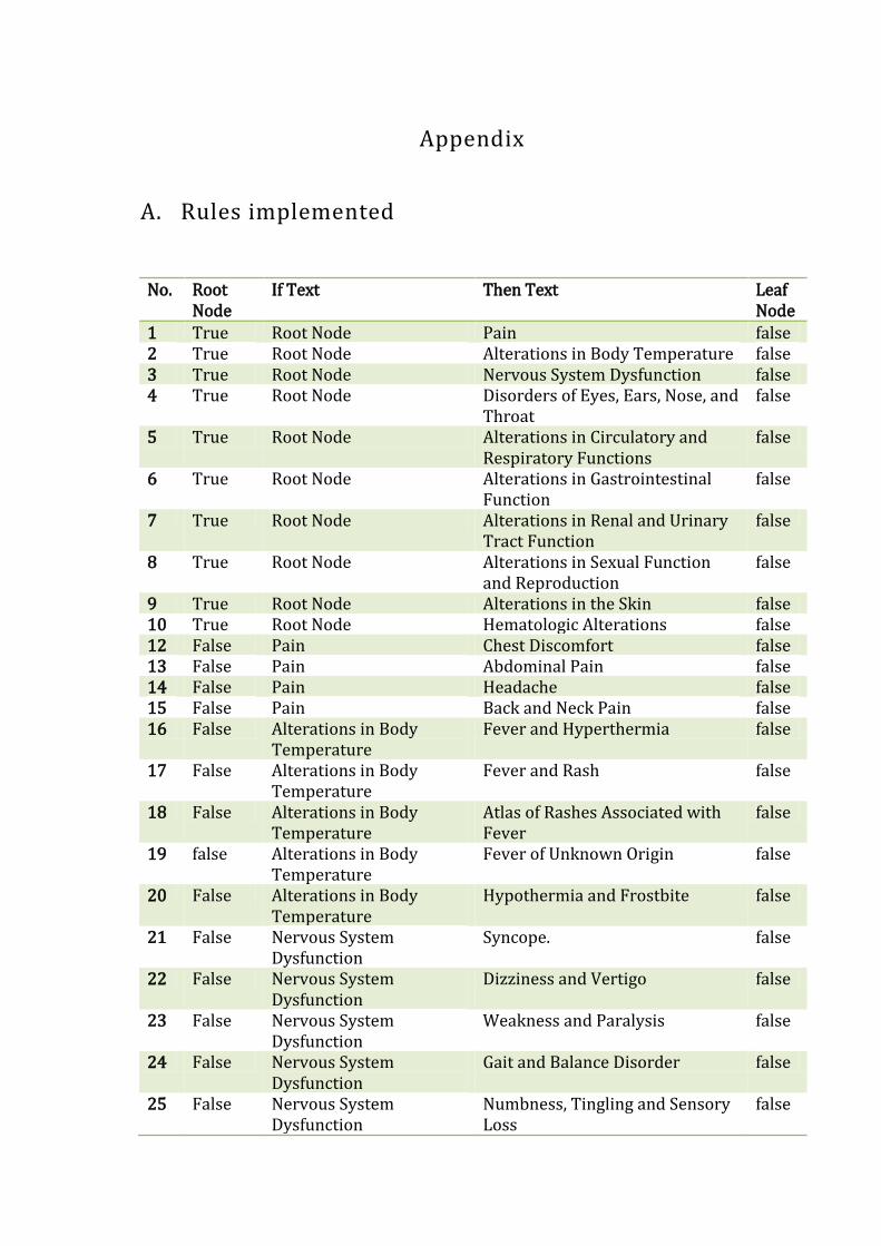
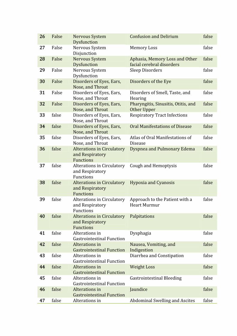
A. Rules implemented ...................................................................................................................................... 47
1 INTRODUCTION
1.1 Background
Our mental capacities are so important to our everyday lives and our sense of self that
humankind has given itself the scientific name homo-sapiens; man the wise. The field of
artificial intelligence (AI) attempts to understand these capacities better known as
intelligent entities. AI being a broad topic combines computer science, physiology and
philosophy. One of the large scale applications of the field of AI is the development of
expert systems. An expert system is a knowledge-based computer program containing
knowledge of human experts in a particular domain. Among the various types of expert
systems, this project reports the development of a hybrid expert system which is an
integration of rule-based reasoning and case-based reasoning techniques.
Rule-based system is used when problem area is narrow and the domain has well-
understood theory. To overcome these limitations, case-based reasoning technique is
also integrated. This solves new problems based on the solutions of similar past
problems rather than merely using rules. These expert systems are extensively used in
the various fields of medicine, especially for diagnosis purposes. They are already
implemented to help the diagnosis process relating to blood infections, heart problems
and kidney disorders. This project concerns the implementation of a system for the
neurology domain. Neurology deals with disorders of the nervous system with all
categories of disease involving the central, peripheral, and autonomic nervous systems,
including their coverings, blood vessels, and all effectors tissue, such as muscle.

1.2 Objectives
Following were the main objectives of the project.
1. To develop a web based hybrid expert system to help the neurology diagnosis
process.
2. To review Artificial Intelligence literature in Expert Systems and estimate the
Expert System model that fits in the domain of neurology.
1.3 Project Overview
This project is about a system that helps in the diagnosis of neurologic disorders. It
uses artificial reasoning techniques to assist the diagnosis process. A person will
require at least some familiarity with the neurology domain to use the system. This is
because the system is built around clinical examination terms and medical jargons
that common people are not familiar with. The system implements two major
reasoning techniques that human beings use, to assist the diagnosis process. One part
of the system, called the rule-based component, is embodied with the diagnosis
knowledge that guides the user to find probable diseases in step-by-step process where
options are provided at each step. The other part, called the case-based component is like
a learning machine that makes better predictions every time it encounters a new case.
The two components operate independently and may be used one at a time.
Reasoning performed by recalling the theories that we have learnt is called rule-
based reasoning and that by remembering similar cases or scenarios is case-based
reasoning. Rule-based reasoning is implemented in the system by encoding the
domain knowledge into the database and case-based reasoning is implemented such
that the system keeps learning as it encounters new cases. Neurology is a medical
specialty that deals with disorders of the nervous system. Interested users like health
assistants can use the website as a helpful tool to diagnose patients or even
themselves. The web application was built by encoding rules of the neurology domain
and by developing a framework to learn from the cases of the patients. Integrating the
techniques of rule-based reasoning and case-based reasoning a hybrid system was
constructed.
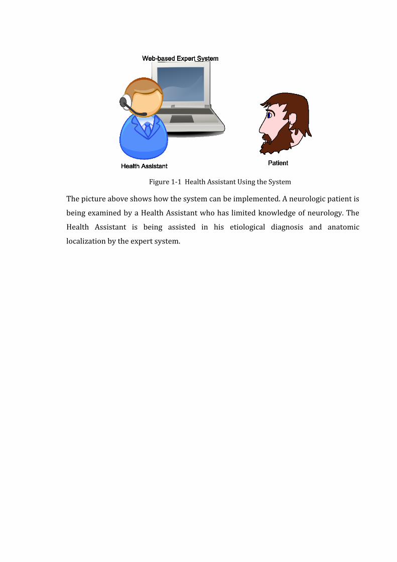
Figure 1-1 Health Assistant Using the System
The picture above shows how the system can be implemented. A neurologic patient is
being examined by a Health Assistant who has limited knowledge of neurology. The
Health Assistant is being assisted in his etiological diagnosis and anatomic
localization by the expert system.
2 LITERATURE REVIEW
2.1 The Neurology Domain
Neurology is a medical specialty dealing with disorders of the nervous system.
Specifically, it deals with the diagnosis and treatment of all categories of disease
involving the central, peripheral, and autonomic nervous systems, including their
coverings, blood vessels, and all effectors tissue, such as muscle. Physicians who
specialize in neurology are called neurologists, and are trained to investigate or diagnose
and treat neurological disorders. Pediatric neurologists treat neurological disease in
children (Lymeneuroborreliosis: peripheral nervous system manifestations, 1990).
Neurology is recognized as a complex medical domain because neurologic diseases
are not visible or palpable. Neurology diagnosis is all about finding a lesion in the
nervous system i.e. either in brain or in spinal cord or in peripheral nerves. Every
neurologic diagnosis involves two main phases. First the clinical data obtained from
the history and examinations are interpreted to arrive at an anatomic localization
that best explains the clinical findings. The anatomic localization, mode of onset, and
laboratory findings are then integrated to establish etiologic diagnosis (Dennis L.
Kasper, 2008 p. 2489).
The variety of presentations of neurologic disease requires a rigorous technique to
allow diagnostic analysis. The bedside examination provides objective data that can
used to localize the pathology, and the clinical history gives clues as to the nature of
this pathology. Many medical specialties use a ‘pattern recognition approach’ to
diagnosis, in which groups of symptoms and signs are considered together as a
disease syndrome. This is less reliable in neurological practice. As in any medical
consultation the clinical history is taken first, thereby setting the scene and the
examination follows. However, it is often important subsequently to review the
history and to reinterpret it in relation to the physical findings.
2.2 Rule-based Reasoning
The idea of rule-based systems is to represent a domain expert’s knowledge in a
form called rules. In a typical rule-based expert system, a rule consists of several
premises and a conclusion. If all the premises are true, then the conclusion is
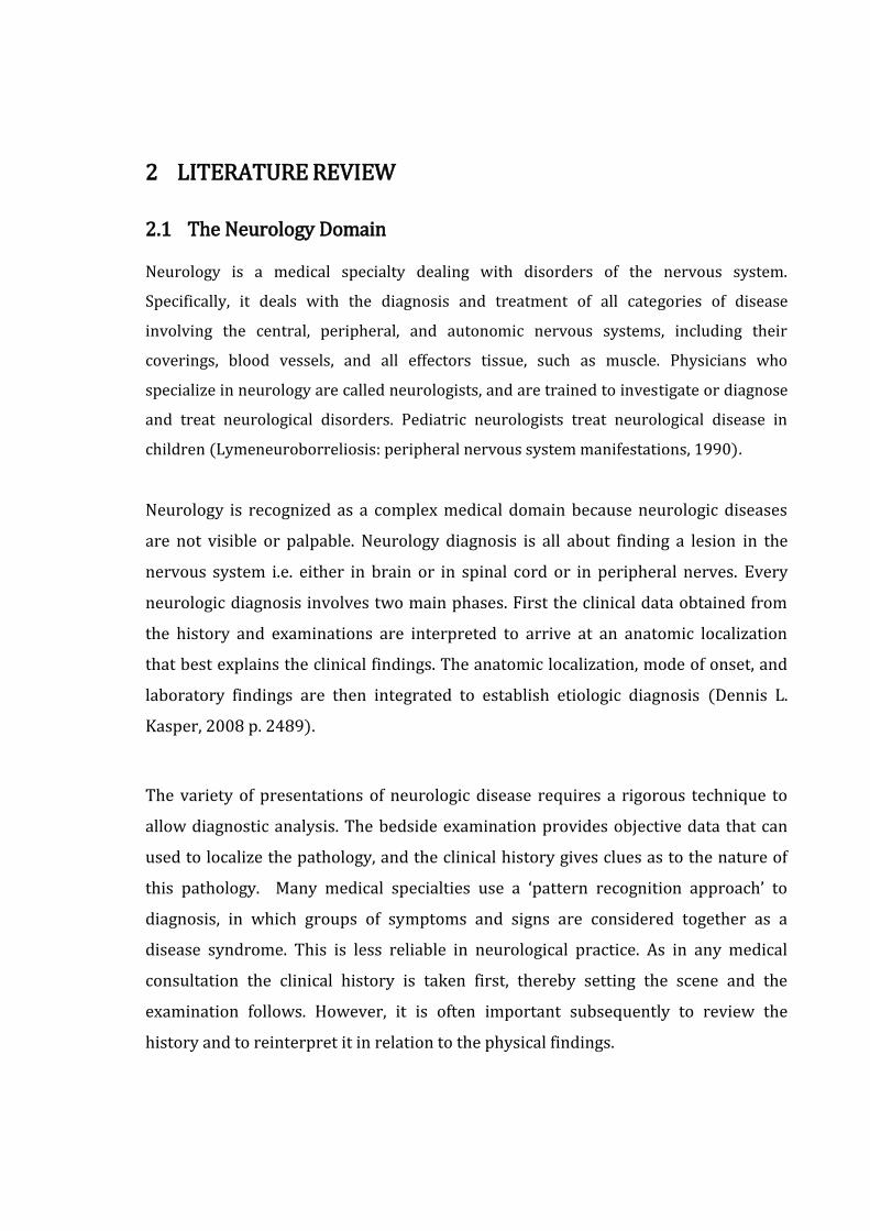
considered true. The components of a rule-based expert system include the
knowledge base, inference engine, knowledge acquisition component, and
explanation system as illustrated in figure below (A Hybrid Expert Systems
Architecture for Yarn Fault Diagnosis, 2007 pp. 43-44).
Figure 2-1 Architecture of a Rule Based Expert System
In the figure above, knowledge base is a declarative representation of the expertise,
often in IF THEN rules. Inference engine is the code at the core of the system, which
derives recommendations from the knowledge base and problem-specific data in
working storage. The knowledge acquisition component acquires new rules that can
be added to the knowledge base by using the knowledge acquisition sub-system. The
explanation sub-system is to explain its advice or recommendations, and even to
justify why a certain action was recommended.
2.3 Case-based Reasoning
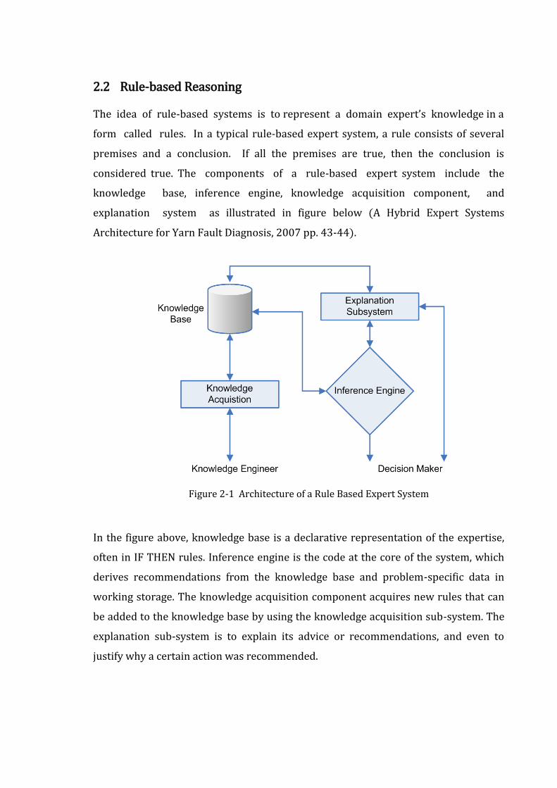
A general CBR cycle may be described by the four basic processes (9th European
Conference on Case Based Reasoning, 2008). An initial description of a problem
defines a new case. This new case is used to retrieve a case from the collection of
previous cases. The retrieved case is combined with the new case - through reuse -
into a solved case. Through the revise process this solution is tested for success, e.g.
by being applied to the real world environment or evaluated by a doctor, and
repaired if failed. During retain, useful experience is retained for future reuse
(Shankar K. Pal, 2004). The cycle is shown below (Case-Based Reasoning:
Experiences, Lessons, and FutureDirections, 1996).
New
case
Learned
Case
Tested
repaired
case
Solved
case
Retrieved
case
REUSE
REVISE
RETAIN
Suggested solution
RETRIEVE
Confirmed solution
Problem
Previous
cases
Domain/General
knowledge
New
Case
Figure 2-2 Case-based Reasoning Life Cycle
2.4 Hybrid Expert Systems
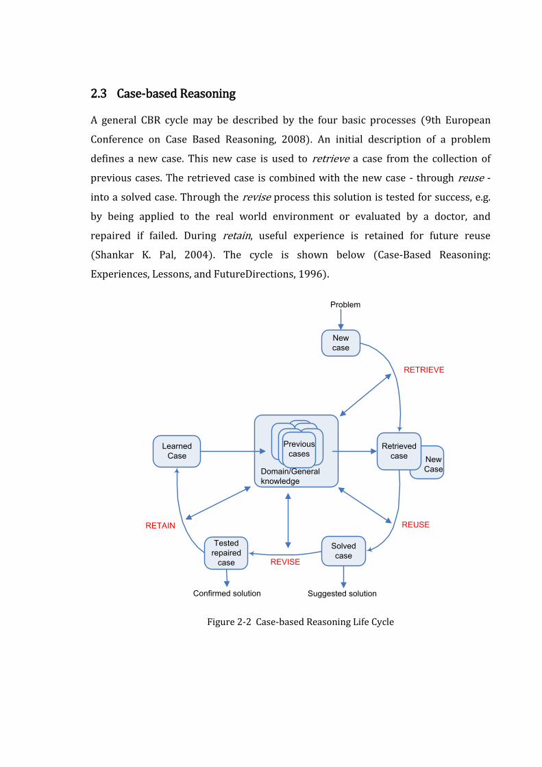
Hybrid expert systems are the integration of rule-based and case-based systems. Rule-
based systems handle problems with well-defined knowledge bases, which limit the
flexibility of such systems. To overcome this inherent weakness of rule-based systems,
case-based reasoning is adopted to improve the performance of the expert system by
incorporating previous cases in the generation of new cases.
Figure 2-3 Integration of Rule-based and Case-based Reasoning
By applying this new approach shown in the diagram above (An Integrated Approach
of rule-based and case-based reasoning for decision support, 1991), a system is able
to capture both explainable and unexplainable expertise from these two
reasoning mechanisms and generate more effective plans for diagnosis support.
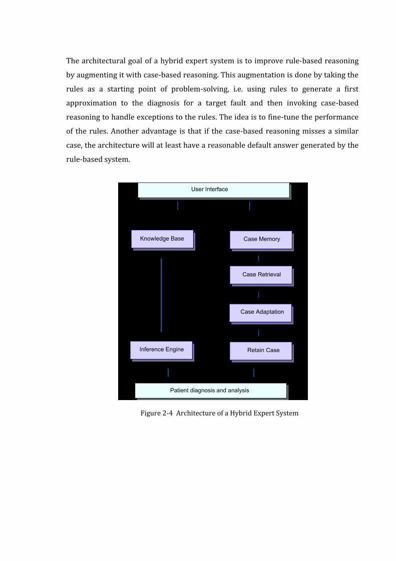
The architectural goal of a hybrid expert system is to improve rule-based reasoning
by augmenting it with case-based reasoning. This augmentation is done by taking the
rules as a starting point of problem-solving, i.e. using rules to generate a first
approximation to the diagnosis for a target fault and then invoking case-based
reasoning to handle exceptions to the rules. The idea is to fine-tune the performance
of the rules. Another advantage is that if the case-based reasoning misses a similar
case, the architecture will at least have a reasonable default answer generated by the
rule-based system.
Figure 2-4 Architecture of a Hybrid Expert System
2.5 Expert systems for Medical Diagnosis
Expert systems have already been applied in a number of different applications in
medicine. Expert systems are not really replacing doctors but are being used to help
them. Some real expert systems for medical diagnostic support are:
1. Dxplain (Lester, 2008).
2. Germwatcher (Washington University, 2007).
3. PEIRS (Dept. of Medical Computer Science, 2007).
4. MYCIN (University, 2003).
5. SHYSTER-MYCIN (University, 2003).
The advantages of using an expert system over the mere dependence on doctors are
mentioned below.
A large database of knowledge can be added to and kept up-to-date - it can
store more knowledge than a person.
The system cannot 'forget' or get facts wrong.
It survives forever. There is no loss of knowledge as there is when a doctor
retires.
The computer can access specialist knowledge that a doctor may not have.

2.6 Apache Tomcat as Application Server
Apache Tomcat was opted as the application server for the project. It is a Servlet
container developed by the Apache software foundation (ASF). Tomcat implements
the Java Servlet and the JavaServer Pages (JSP) specifications from Sun Micro
Systems, and provides a "pure Java" HTTP web server environment for Java code to
run.
Tomcat should not be confused with the Apache web server, which is a C
implementation of an HTTP web server; these two web servers are not bundled
together. Apache Tomcat includes tools for configuration and management, but can
also be configured by editing XML configuration files.
Some Important Features of Tomcat 6.x
Implements the Servlet 2.5 and JSP 2.1 specifications
Support for Unified Expression Language 2.1
Designed to run on Java SE 5.0 and later
Support for Comet through the CometProcessor interface
Is not packaged with an admin console as in past releases.

2.7 Eclipse as Programming IDE
Eclipse was used as IDE for project development. Eclipse is a multi-language software
development platform comprising an IDE and a plug-in system to extend it. It is
written primarily in Java and is used to develop applications in this language and, by
means of the various plug-ins, in other languages as well—C/C++, Cobol, Python,
Perl, PHP and more.
The initial codebase originated from VisualAge. In its default form it is meant for Java
developers, consisting of the Java Development Tools (JDT). Users can extend its
capabilities by installing plug-ins written for the Eclipse software framework, such as
development toolkits for other programming languages, and can write and contribute
their own plug-in modules. Language packs provide translations into over a dozen
natural languages. Released under the terms of the Eclipse Public License, Eclipse is
free and open source software.
IDE License JVM Platforms GUI builder
Eclipse EPL Yes Windows, Mac OS X, Linux, Solaris
Yes
JBuilder Proprietary Yes Linux, Solaris, Windows Yes
JCreator Proprietary No Windows No
MyEclipse Proprietary Yes Linux, Solaris, Windows Yes
NetBeans CDDL, GPL2 Yes Windows, Mac OS X, Linux, Solaris
Yes
Table 2-1 Comparison of Integrated Development Environments
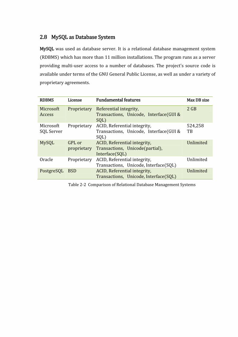
2.8 MySQL as Database System
MySQL was used as database server. It is a relational database management system
(RDBMS) which has more than 11 million installations. The program runs as a server
providing multi-user access to a number of databases. The project's source code is
available under terms of the GNU General Public License, as well as under a variety of
proprietary agreements.
RDBMS License Fundamental features Max DB size
Microsoft Access
Proprietary Referential integrity, Transactions, Unicode, Interface(GUI & SQL)
2 GB
Microsoft SQL Server
Proprietary ACID, Referential integrity, Transactions, Unicode, Interface(GUI & SQL)
524,258 TB
MySQL GPL or proprietary
ACID, Referential integrity, Transactions, Unicode(partial), Interface(SQL)
Unlimited
Oracle Proprietary ACID, Referential integrity, Transactions, Unicode, Interface(SQL)
Unlimited
PostgreSQL BSD ACID, Referential integrity, Transactions, Unicode, Interface(SQL)
Unlimited
Table 2-2 Comparison of Relational Database Management Systems
2.9 Spring Web MVC Framework
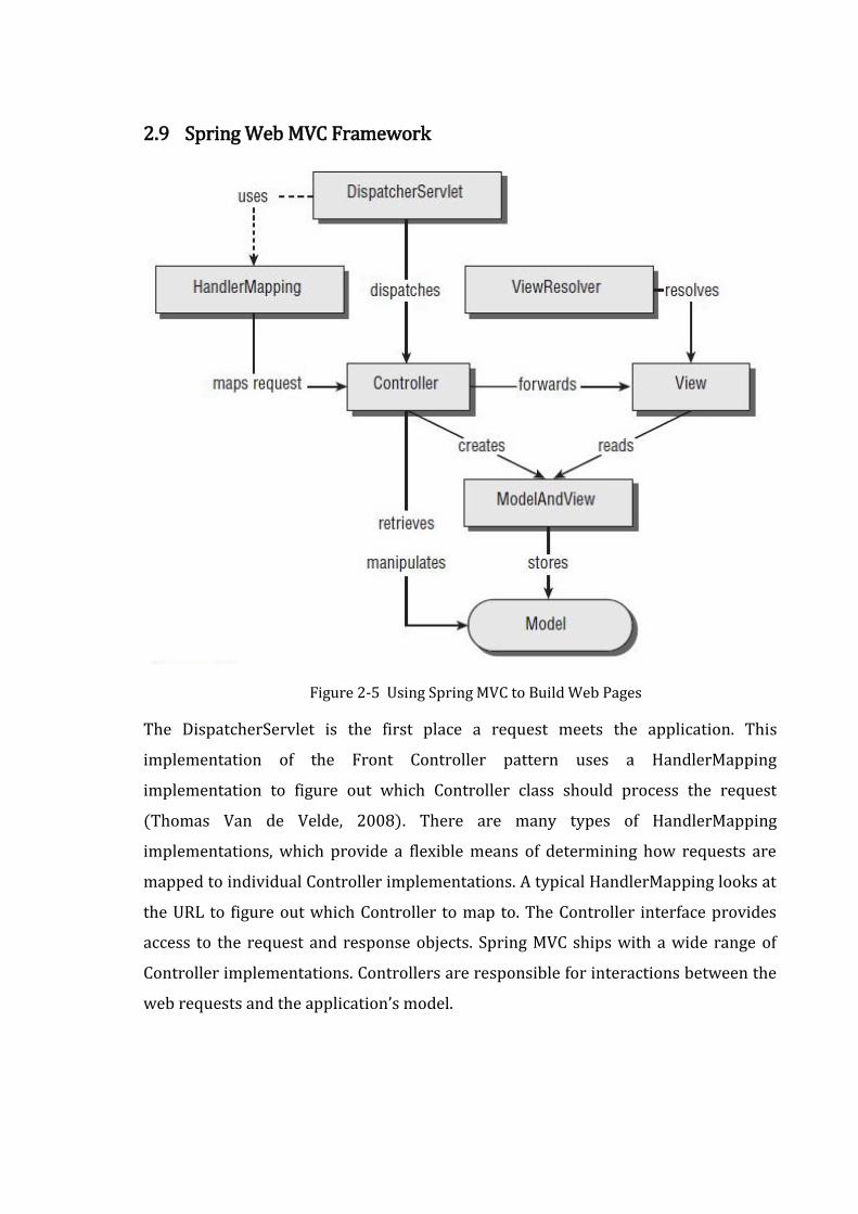
Figure 2-5 Using Spring MVC to Build Web Pages
The DispatcherServlet is the first place a request meets the application. This
implementation of the Front Controller pattern uses a HandlerMapping
implementation to figure out which Controller class should process the request
(Thomas Van de Velde, 2008). There are many types of HandlerMapping
implementations, which provide a flexible means of determining how requests are
mapped to individual Controller implementations. A typical HandlerMapping looks at
the URL to figure out which Controller to map to. The Controller interface provides
access to the request and response objects. Spring MVC ships with a wide range of
Controller implementations. Controllers are responsible for interactions between the
web requests and the application’s model.
A controller typically retrieves data from the request. When processing web forms,
such as a new case submission page, the Controller invokes validation logic and
passes the form’s data to the model for storage in a database. When the controller is
done processing the request, it typically returns a ModelAndView class. The
ModelAndView class defines a logical view name, which is resolved to an actual view
implementation with the help of a ViewResolver. The view interface was
implemented as JSP. The controller has no knowledge about the actual
implementation, as the ViewResolver is ultimately responsible for mapping view
names to actual implementations. This decoupling of the view’s name and the actual
implementation provided for added flexibility.
3 PROJECT MANAGEMENT
3.1 Project Configuration and Management
The project configuration and management was carried out in D2Labs at
http://dev.d2labs.org/gf/project/nds/. The tool and the resources were used for the
following purposes:
1. Maintaining the source codes at the SVN repository.
2. Publishing project news.
3. Discussing the project related issues through the forums.
4. Maintaining the project artifacts.
5. Assigning tasks to the team members and maintaining the trackers.
Figure 3-1 SVN Commit Statistics at the SVN Repository
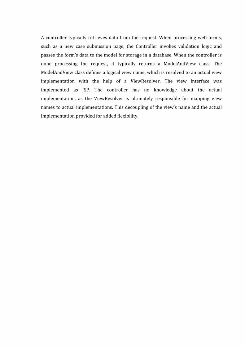
The graph above (Figure 3-1 SVN Commit Statistics at the SVN Repository) depicts
the number of SVN commits of the source code at the SVN repository at different
months during the project development. There were minimal activities at the mid-
duration because of exams. Obviously, last month was a busy one, which the graph
proves.
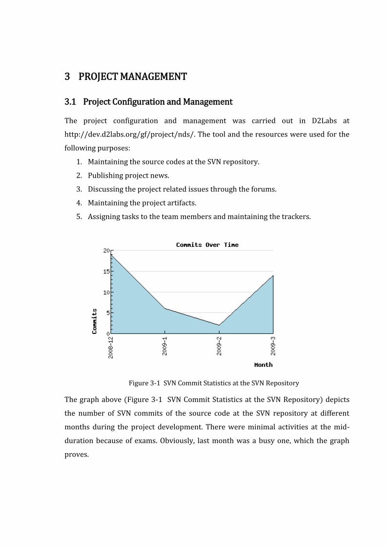
3.2 Project Workflow and Schedule
Phases Effort (person-hrs)
Planning & Monitoring 42
Requirements 80
High level design 30
Detail Design 140
Implementation 460
Code Integration 90
System Testing 70
Internal Presentation 24
Final Presentation 24
Total Estimated Effort 960
Table 3-1 Project Phases and Effort Required
Team Size: 4
Total effective project duration: approx 16 weeks
Effort required per person: 20 hours per week
3.3 Management Plan
3.3.1 Team
Resource Roles
Prof. Dr. Shashidhar Ram Joshi Supervisor
Er. Bikram Lal Shrestha Mentor
Badri Adhikari Team lead
Md. Hasan Ansari Team member
Priti Shrestha Team member
Susma Pant Team member
Table 3-2 Team Resource and Roles
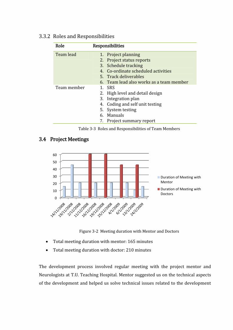
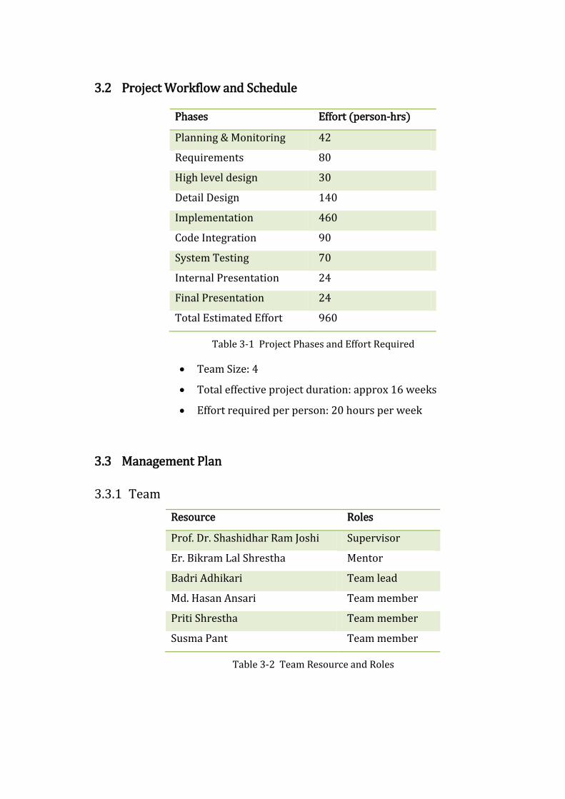
3.3.2 Roles and Responsibilities
Role Responsibilities
Team lead 1. Project planning 2. Project status reports 3. Schedule tracking 4. Co-ordinate scheduled activities 5. Track deliverables 6. Team lead also works as a team member
Team member 1. SRS 2. High level and detail design 3. Integration plan 4. Coding and self unit testing 5. System testing 6. Manuals 7. Project summary report
Table 3-3 Roles and Responsibilities of Team Members
3.4 Project Meetings
Figure 3-2 Meeting duration with Mentor and Doctors
Total meeting duration with mentor: 165 minutes
Total meeting duration with doctor: 210 minutes
The development process involved regular meeting with the project mentor and
Neurologists at T.U. Teaching Hospital. Mentor suggested us on the technical aspects
of the development and helped us solve technical issues related to the development
0
10
20
30
40
50
60
Duration of Meeting with Mentor
Duration of Meeting with Doctors
activities. Doctors helped us understand the domain more clearly and provided us
with the knowledge to perform knowledge engineering.
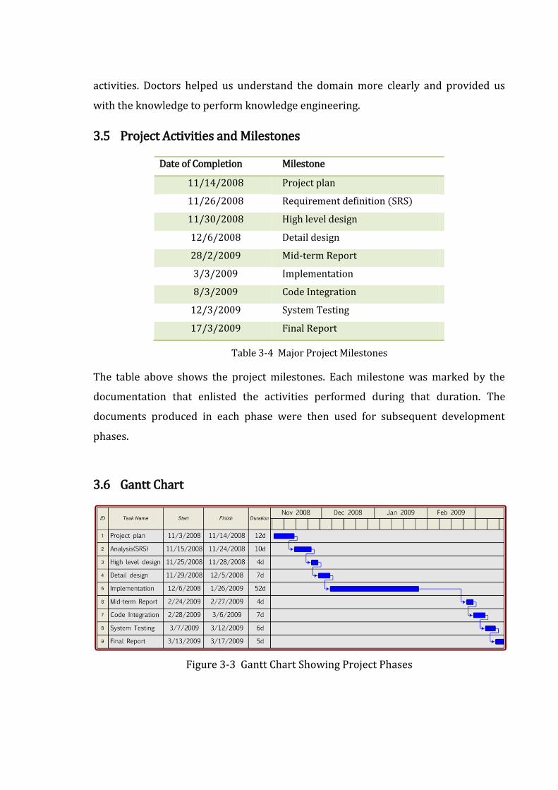
3.5 Project Activities and Milestones
Date of Completion Milestone
11/14/2008 Project plan
11/26/2008 Requirement definition (SRS)
11/30/2008 High level design
12/6/2008 Detail design
28/2/2009 Mid-term Report
3/3/2009 Implementation
8/3/2009 Code Integration
12/3/2009 System Testing
17/3/2009 Final Report
Table 3-4 Major Project Milestones
The table above shows the project milestones. Each milestone was marked by the
documentation that enlisted the activities performed during that duration. The
documents produced in each phase were then used for subsequent development
phases.
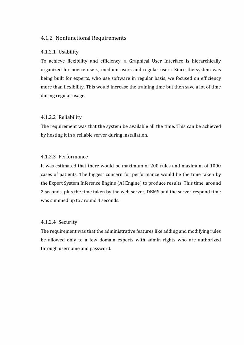
3.6 Gantt Chart
Figure 3-3 Gantt Chart Showing Project Phases

4 SYSTEM ANALYSIS
4.1 Requirement Specification
4.1.1 Functional Requirements
4.1.1.1 Maintain Cases
This requirement was concerned about maintaining cases of the patients to provide
functionalities for searching existing cases and inserting, modifying and removing
cases.
4.1.1.2 Maintain Rules
This requirement was concerned about developing a feature for updating the rules of
the domain. Rules that are in a predefined format such as, ‘IF symptom THEN disease
OR further diagnosis’ need to be validated before inserting or modifying to check if it
is in the appropriate format. The features included adding rules, modifying existing
rules and deleting rules.
4.1.1.3 Provide Expert System Solution
This functional requirement explained that the rule-based engine would process the
supplied case and the rules to arrive at a solution that would give the list of diseases
and the suggestions for further diagnosis. It also described that the case-based engine
would compare the supplied case against the past cases to retrieve the most similar
cases from the case base.
4.1.1.4 User Interface
The requirement of this functionality was to provide facilities to interact with the
user, collect data, forward them to the back end, receive data from the back-end and
to display them for the user.
4.1.2 Nonfunctional Requirements
4.1.2.1 Usability
To achieve flexibility and efficiency, a Graphical User Interface is hierarchically
organized for novice users, medium users and regular users. Since the system was
being built for experts, who use software in regular basis, we focused on efficiency
more than flexibility. This would increase the training time but then save a lot of time
during regular usage.
4.1.2.2 Reliability
The requirement was that the system be available all the time. This can be achieved
by hosting it in a reliable server during installation.
4.1.2.3 Performance
It was estimated that there would be maximum of 200 rules and maximum of 1000
cases of patients. The biggest concern for performance would be the time taken by
the Expert System Inference Engine (AI Engine) to produce results. This time, around
2 seconds, plus the time taken by the web server, DBMS and the server respond time
was summed up to around 4 seconds.
4.1.2.4 Security
The requirement was that the administrative features like adding and modifying rules
be allowed only to a few domain experts with admin rights who are authorized
through username and password.
4.2 Cost-Benefit Analysis
Cost-benefit analysis is a term that refers both to:
a formal discipline used to help appraise, or assess, the case for a project or
proposal, which itself is a process known as project appraisal; and
an informal approach to making decisions of any kind.
A hallmark of CBA is that all benefits and all costs are expressed in money terms, and
are adjusted for the time value of money, so that all flows of benefits and flows of
project costs over time (which tend to occur at different points in time) are expressed
on a common basis in terms of their present value. Closely related, but slightly
different, formal techniques include Cost-effectiveness analysis, Economic impact
analysis, Fiscal impact analysis and Social Return on Investment (SROI) analysis.
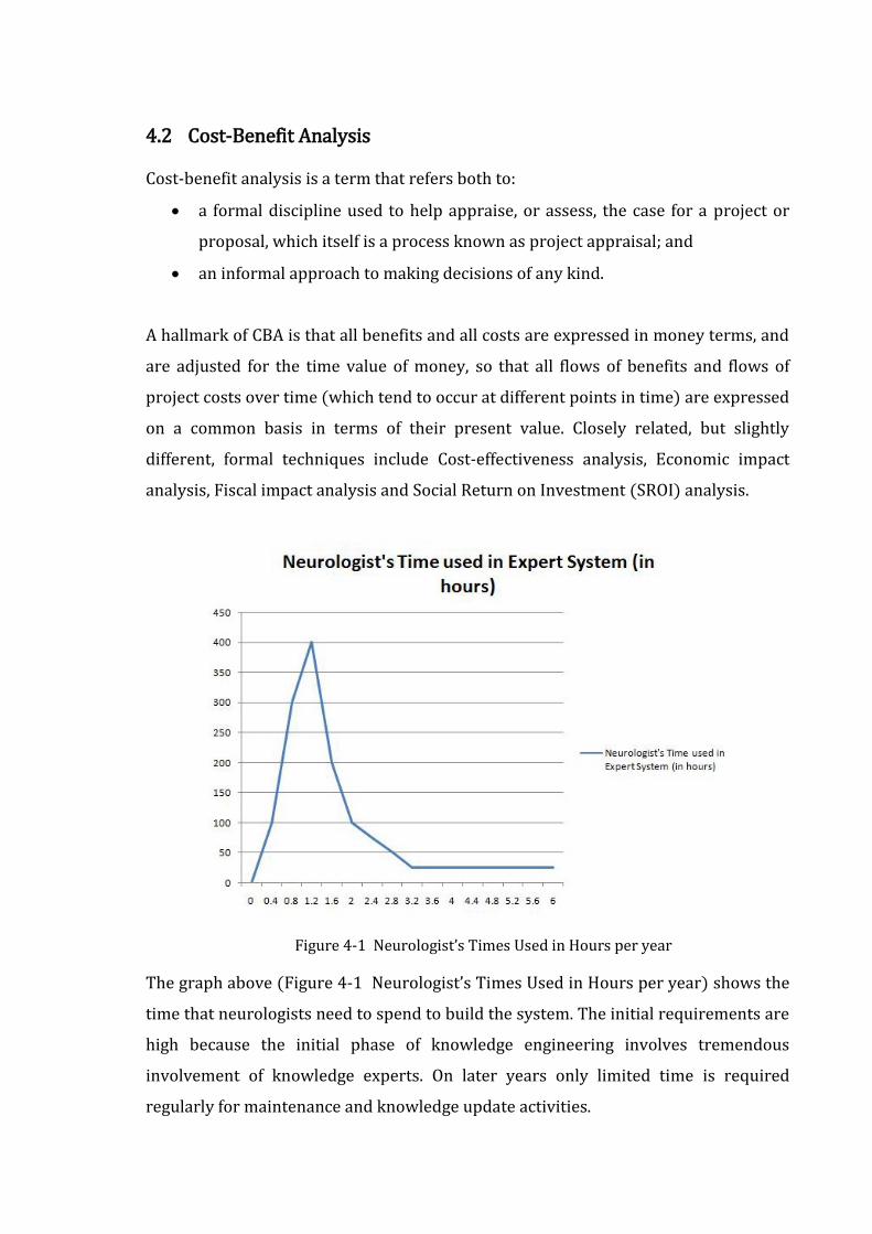
Figure 4-1 Neurologist’s Times Used in Hours per year
The graph above (Figure 4-1 Neurologist’s Times Used in Hours per year) shows the
time that neurologists need to spend to build the system. The initial requirements are
high because the initial phase of knowledge engineering involves tremendous
involvement of knowledge experts. On later years only limited time is required
regularly for maintenance and knowledge update activities.
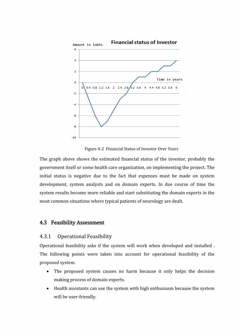
Figure 4-2 Financial Status of Investor Over Years
The graph above shows the estimated financial status of the investor, probably the
government itself or some health care organization, on implementing the project. The
initial status is negative due to the fact that expenses must be made on system
development, system analysts and on domain experts. In due course of time the
system results become more reliable and start substituting the domain experts in the
most common situations where typical patients of neurology are dealt.
4.3 Feasibility Assessment
4.3.1 Operational Feasibility
Operational feasibility asks if the system will work when developed and installed .
The following points were taken into account for operational feasibility of the
proposed system.
The proposed system causes no harm because it only helps the decision
making process of domain experts.
Health assistants can use the system with high enthusiasm because the system
will be user-friendly.

The system is affordable and has low operational cost because it requires no
special equipments other than a normal computer.
4.3.2 Technical Feasibility
Technical feasibility involves determining whether or not a system can actually be
constructed to solve the problem at hand (Mall, 2006). The following points were
considered for the project’s technical feasibility.
The required technologies (rule based and case based reasoning techniques,
programming languages and architecture) existed.
The database management tool (MySQL) was found technically capable to
hold data required to install and use the system.
The proposed system can provide adequate response to inquiries regardless of
the number or location of users. This is because the system is web enabled and
the application server is considerably sufficient to support the number of
users.
Ease of access was guaranteed but the technical guarantees of accuracy and
reliability would depend upon the data collected.
4.3.3 Economic Feasibility
The economic feasibility of the project can be shown through the following points.
The tools and technologies used for the system are free for non commercial
development purposes. Most of them are licensed under GNU GPL.
Since the project will be implemented in service sector, the quality of
information and the ease of access are the main concern. The system can prove
effective and efficient and can establish itself as a valuable asset of the
government and the one who implements.
It can be assured that the project proves economically feasible because the
system will be maintained by doctors and the government or non-government
health service oriented organizations.

5 HIGH LEVEL DESIGN AND DETAILED DESIGN
5.1 High Level Design
5.1.1 System architecture
Figure 5-1 System Architecture
The system comprises to two major components: Case-based reasoning component
and the Rule-based reasoning component. These two components operate separately
to give the expert system solution.
5.1.2 Context Diagram
Figure 5-2 Context Diagram
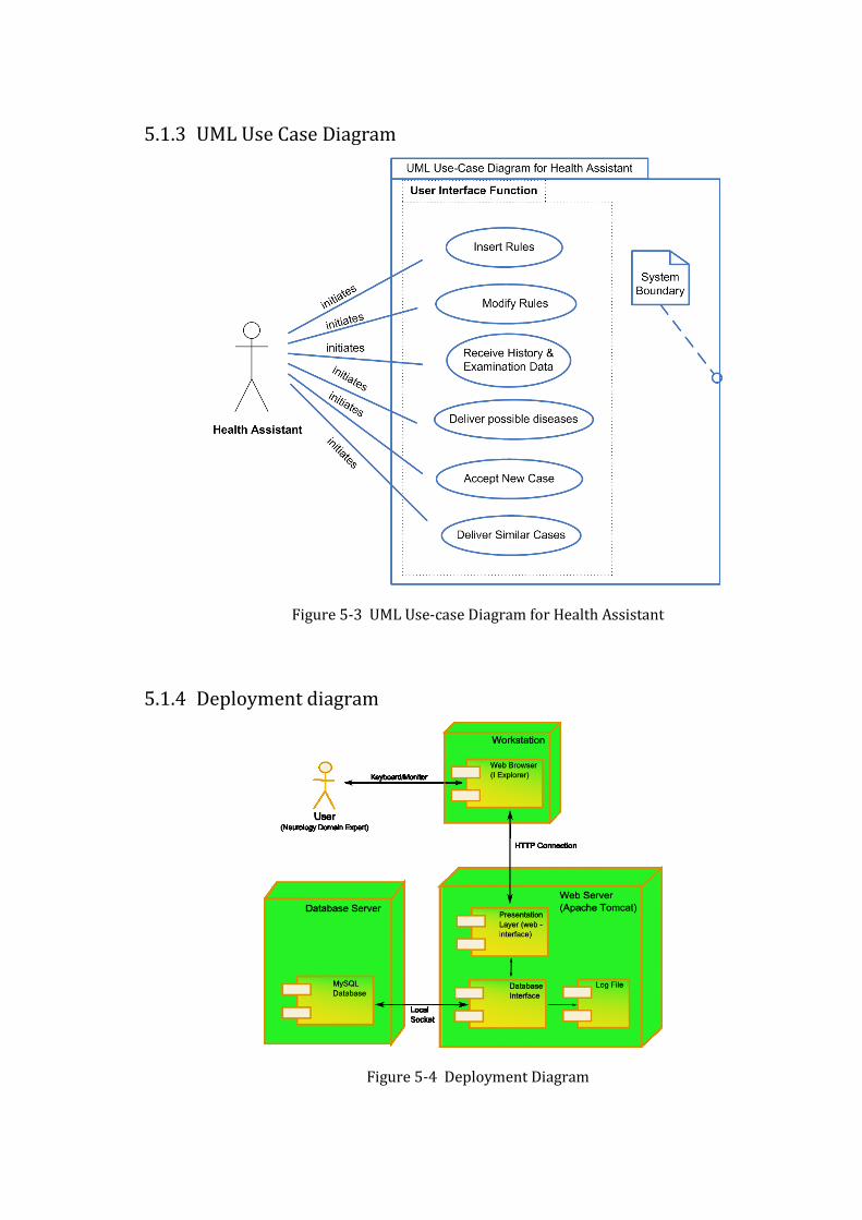
5.1.3 UML Use Case Diagram
Figure 5-3 UML Use-case Diagram for Health Assistant
5.1.4 Deployment diagram
Figure 5-4 Deployment Diagram
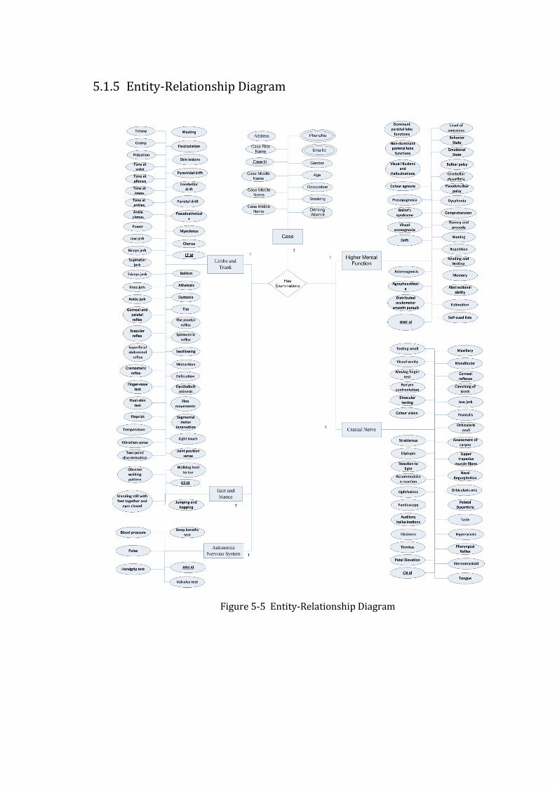
5.1.5 Entity-Relationship Diagram
Figure 5-5 Entity-Relationship Diagram
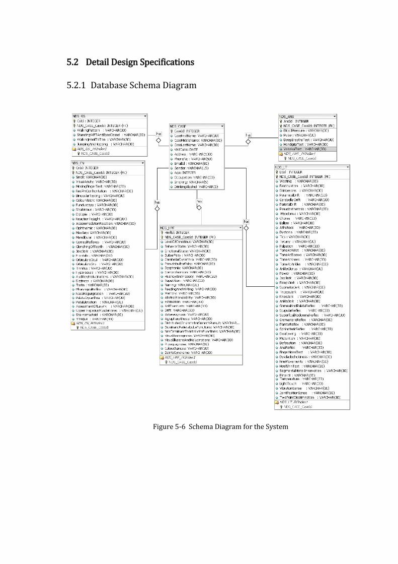
5.2 Detail Design Specifications
5.2.1 Database Schema Diagram
Figure 5-6 Schema Diagram for the System
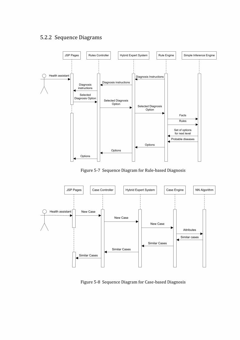
5.2.2 Sequence Diagrams
JSP Pages Rules Controller Hybrid Expert System Rule Engine
Health assistant
Simple Inference Engine
Selected
Diagnosis Option
Diagnosis Instructions
Diagnosis instructionsDiagnosis
instructions
Selected Diagnosis
OptionSelected Diagnosis
Option
Facts
Rules
Set of options
for next level
Probable diseases
Options
Options
Options
Figure 5-7 Sequence Diagram for Rule-based Diagnosis
JSP Pages Case Controller Hybrid Expert System Case Engine
Health assistant
NN Algorithm
New Case
Similar cases
New Case
New Case
Attributes
Similar Cases
Similar Cases
Similar Cases
Figure 5-8 Sequence Diagram for Case-based Diagnosis
6 IMPLEMENTATION
6.1 Tools Used for System Development
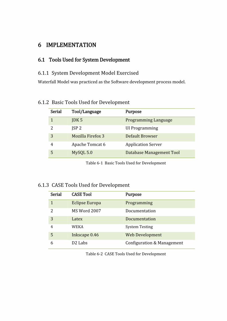
6.1.1 System Development Model Exercised
Waterfall Model was practiced as the Software development process model.
6.1.2 Basic Tools Used for Development
Serial Tool/Language Purpose
1 JDK 5 Programming Language
2 JSP 2 UI Programming
3 Mozilla Firefox 3 Default Browser
4 Apache Tomcat 6 Application Server
5 MySQL 5.0 Database Management Tool
Table 6-1 Basic Tools Used for Development
6.1.3 CASE Tools Used for Development
Serial CASE Tool Purpose
1 Eclipse Europa Programming
2 MS Word 2007 Documentation
3 Latex Documentation
4 WEKA System Testing
5 Inkscape 0.46 Web Development
6 D2 Labs Configuration & Management
Table 6-2 CASE Tools Used for Development
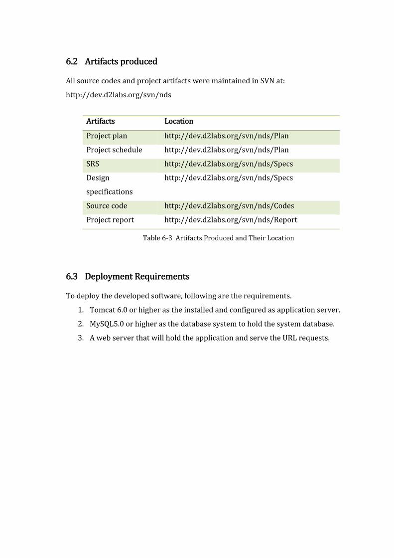
6.2 Artifacts produced
All source codes and project artifacts were maintained in SVN at:
http://dev.d2labs.org/svn/nds
Artifacts Location
Project plan http://dev.d2labs.org/svn/nds/Plan
Project schedule http://dev.d2labs.org/svn/nds/Plan
SRS http://dev.d2labs.org/svn/nds/Specs
Design
specifications
http://dev.d2labs.org/svn/nds/Specs
Source code http://dev.d2labs.org/svn/nds/Codes
Project report http://dev.d2labs.org/svn/nds/Report
Table 6-3 Artifacts Produced and Their Location
6.3 Deployment Requirements
To deploy the developed software, following are the requirements.
1. Tomcat 6.0 or higher as the installed and configured as application server.
2. MySQL5.0 or higher as the database system to hold the system database.
3. A web server that will hold the application and serve the URL requests.

6.4 Decision Tree Implemented
Sleep Disorders
Aphasia, Memory
Loss and Other
facial cerebral
disorders
Memory LossConfusion and
Delirium
Numbness,
Tingling and
Sensory Loss
Gait and Balance
DisorderSyncope
Dizziness and
Vertigo
Weakness and
Paralysis
Harrison page 1
Weakness in
Restricted
Distribution
Proximal
WeaknessDistal WeaknessMonoparesisHemiparesis Pareparesis
Quadriparesis or
Generalized
Weakness
Definition of all the
terms below:
Begin Neurologic
Examinaiton
Examine the
Motor System of
the Limbs and
Trunk
Examine the
Sensory System
of the Limbs and
Trunk
Examine Level of
Consciuosness
Examine Cognitive
Function
Examine Cranial
Nerves
Examine Eye
Movements and
Pupils
Examine
Trigeminal Nerve
(V)
Examine Facial
Nerve (V)
Examine
Vestibulocochlear
Nerve (VIII)
Examine Vagus
Nerve (X)
Examine
Glossopharyngeal
Nerve (XII)
Examine
Hypoglossal
Nerve (XII)
Examine
Accessory Nerve
(XI)
Examine Stance
and Gait
Examine
Autonomic
Nervous System
Lower Motor Neuron
Signs or Myopathic
Signs
Upper Motor
Neuron Signs
Lesion in Spinal
CordLesion in Brain
Extradural
diseases
Sudden OnsetGradual Onset
Sudden Onset
Sacral cord/
Conus MedullarisCervical Cord
Compressive
MyelopathyNoncompressive
Myelopathy
Cerebral diplegiaParasagittal
meningiomia
Cerebral Causes
Bullet injury at
paracentral lobule
Thrombosis of
unpaired anterior
cerebral artery
Superior sagittal
sinus thrombosis
Cerebral Causes
Arteriovenous
malformationsMeningiomia Neurofibroma
Patchy
arachnoiditis
(tuberclosis,
syphilis)
Intradural diseases
Extramedullary
haematopoiesis in
thalassaemia
Fracture or
dislocation of the
vertebra
Degenerative joint
disease
(spondylosis)
Prolapsed
intervertebral disc
(PID)
Caries spine
(Plott’s paraplegia)
Myeloma,
lymphomatous or
metastatic
deposits in the
vertebra;
osteomyelitis
Patchy meningitis Spinal Epidural
Abscess
Injury to the spinal
cord (fracture-
dislocation or
collapse of the
vertebra)
Prolapsed
intervertebral disc
(PID)
Spinal epidural
abscessRadiation
myelpathyPost-vaccinal
Haematomyelia (from
arteriovenous
malformations,
angiomas, or
endarteritis)
Thrombosis of
anterior spinal
artery
(myelomalacia)
Acute Transverse
Myelitis
medullary
Gradual Onset
Compressive
Myelopathy Noncompressive
Myelopathy
Thoracic Cord Lumbar Cord
Figure 6-1 Decision Tree for Quadriplegia/Paraplegia
The figure above shows decision tree that provides routes to identify probable
diseases by traversing down the levels. The decision tree is for a part of the neurology
domain called Quadriplegia/Paraplegia that deals with the weakness of arms and
legs.

6.5 Nearest Neighbor Algorithm for Case Retrieval
The Nearest-Neighbor algorithm was implemented for retrieving most similar cases
from the case-base which operates as explained in the following steps:
1. Receive new case as an input to the algorithm.
2. Prepare the data structure to hold case and its associated similarity value with
the new case. Set maximum similarity to one and minimum to zero.
3. Begin retrieving all cases from the database one by one serially.
4. For each case retrieved from database, begin:
i. Set a numeric variable total similarity to 0.
ii. For each attribute in the attribute list of the cases, loop2
If (attribute X of new case is not ‘null’ and attribute X of
retrieved case is not ‘null’)
Then increase the total similarity by sim(fX NC,fXRC)
iii. Store the cases and their total similarities in the data structure defined
in Step 3.
5. Compare the total similarity values of all the cases and arrange them in
ascending order.
6. Prepare array of cases with minimum number of similar cases required as
input.
7. Return the array as the output of the algorithm.

7 TESTING
7.1 Implementation of Nearest Neighbor Algorithm
The output of the Nearest Neighbor Algorithm was tested against the results obtained
from WEKA, a data mining tool. A set of 50 different cases was prepared. These cases
were represented in the format required by WEKA and Simple K-Means algorithm
was applied with K as 17. Then cluster analysis was performed after adding one more
case as a new case. The result of cluster analysis was noticed to identify 2 cases that
were nearest to the new case. Same cases were inserted into the case base of the
system as learnt cases. Then the same new case was provided as the input. The
similar cases displayed by the system, were found to be exactly same as those shown
by WEKA.
Technology Used Input Output
WEKA 1. A set of 50 different cases with unique
ids ranging from 1 to 50.
2. A new case with id 51.
A cluster of 3
cases with ids 12
and 13, and 51.
Neurology Diagnosis
System
1. A set of 50 different cases with unique
ids ranging from 1 to 50.
2. A new case with id 51.
Two cases with
ids 12 and
13.(same)
Table 7-1 Testing of the Nearest Neighbor Algorithm
7.2 Unit Testing
Unit testing was undertaken when a module was coded and successfully reviewed.
Various driver modules and stubs were prepared for the same. Modules required to
provide the necessary environment were not available so stubs and drivers were
designed to provide complete environment for the modules under test. Stub
procedures were developed for testing purpose that had the same I/O parameters as
units under test but these has a highly simplified behavior.
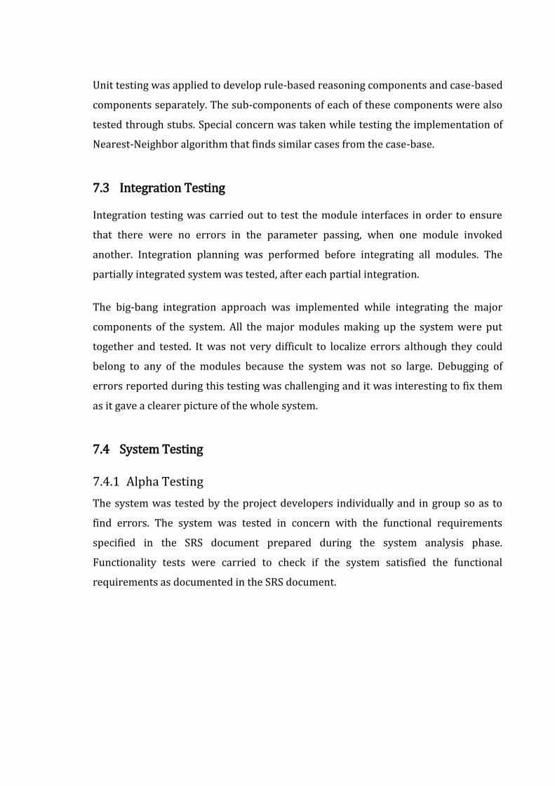
Unit testing was applied to develop rule-based reasoning components and case-based
components separately. The sub-components of each of these components were also
tested through stubs. Special concern was taken while testing the implementation of
Nearest-Neighbor algorithm that finds similar cases from the case-base.
7.3 Integration Testing
Integration testing was carried out to test the module interfaces in order to ensure
that there were no errors in the parameter passing, when one module invoked
another. Integration planning was performed before integrating all modules. The
partially integrated system was tested, after each partial integration.
The big-bang integration approach was implemented while integrating the major
components of the system. All the major modules making up the system were put
together and tested. It was not very difficult to localize errors although they could
belong to any of the modules because the system was not so large. Debugging of
errors reported during this testing was challenging and it was interesting to fix them
as it gave a clearer picture of the whole system.
7.4 System Testing
7.4.1 Alpha Testing
The system was tested by the project developers individually and in group so as to
find errors. The system was tested in concern with the functional requirements
specified in the SRS document prepared during the system analysis phase.
Functionality tests were carried to check if the system satisfied the functional
requirements as documented in the SRS document.

7.4.2 Beta Testing
The system was tested by neurologists at T.U. Teaching Hospital. The system was
used in the Neurology O.P.D. of the Teaching Hospital to check whether it could
actually help in the neurology diagnosis.
Figure 7-1 Results at T.U.T.H. O.P.D.
The pie-chart above shows results when the Rule-based component of the system
was tested at Neurology O.P.D. of T.U. Teaching Hospital. We tested 13 neurologic
patients whose status was input into the system to get probable diseases. Only 2
cases were properly solved by the system. Of all the cases, 3 could not be input to the
system because of the cases being complex (involved not only neurology but other
domains as well). And 8 cases had to be discontinued due to ambiguity in deciding the
options provided by the system.
Solved Cases of Patients, 2
Unapplicable Situations, 3Ambiguity in
decision making, 8
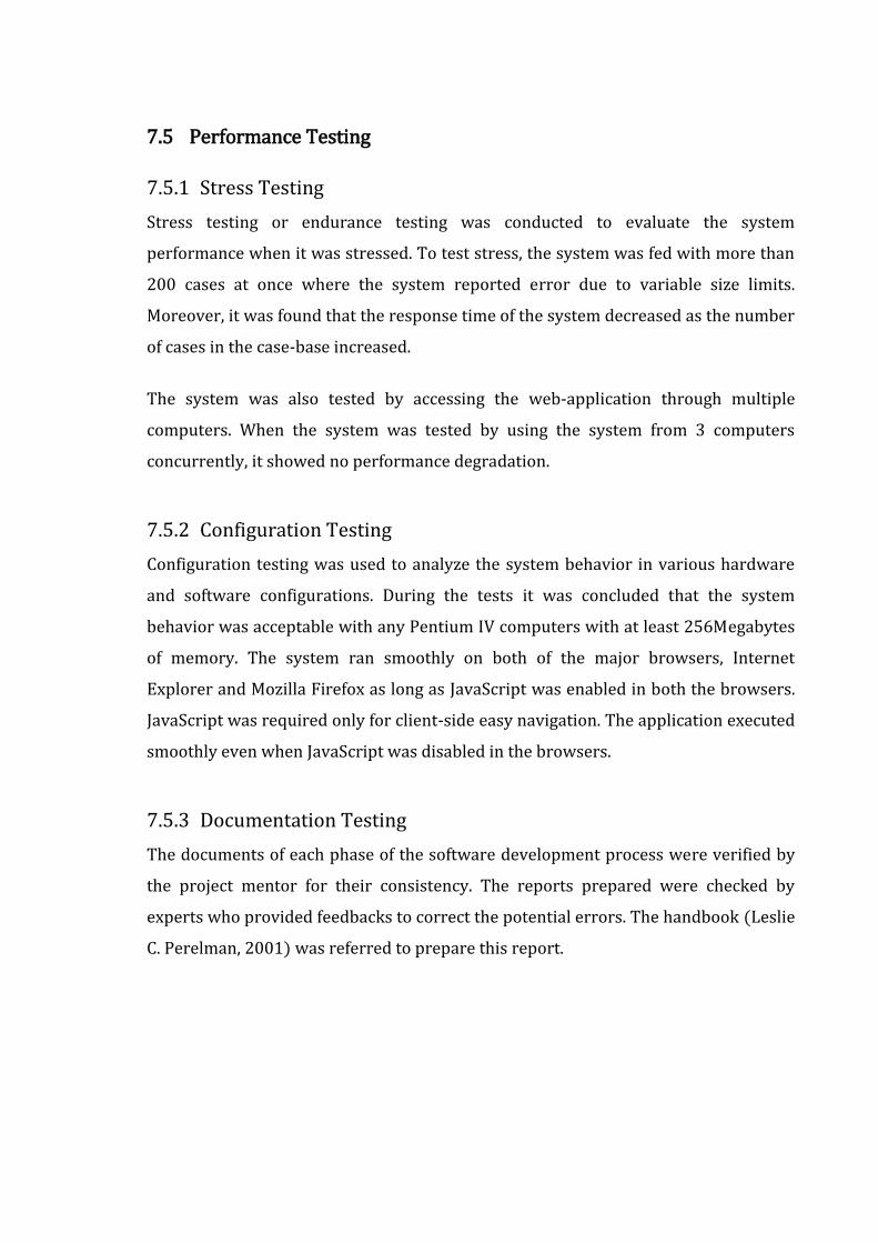
7.5 Performance Testing
7.5.1 Stress Testing
Stress testing or endurance testing was conducted to evaluate the system
performance when it was stressed. To test stress, the system was fed with more than
200 cases at once where the system reported error due to variable size limits.
Moreover, it was found that the response time of the system decreased as the number
of cases in the case-base increased.
The system was also tested by accessing the web-application through multiple
computers. When the system was tested by using the system from 3 computers
concurrently, it showed no performance degradation.
7.5.2 Configuration Testing
Configuration testing was used to analyze the system behavior in various hardware
and software configurations. During the tests it was concluded that the system
behavior was acceptable with any Pentium IV computers with at least 256Megabytes
of memory. The system ran smoothly on both of the major browsers, Internet
Explorer and Mozilla Firefox as long as JavaScript was enabled in both the browsers.
JavaScript was required only for client-side easy navigation. The application executed
smoothly even when JavaScript was disabled in the browsers.
7.5.3 Documentation Testing
The documents of each phase of the software development process were verified by
the project mentor for their consistency. The reports prepared were checked by
experts who provided feedbacks to correct the potential errors. The handbook (Leslie
C. Perelman, 2001) was referred to prepare this report.

8 RESULTS AND DISCUSSIONS
8.1 Results of Rule-based Diagnosis
The series of options to ask the patient during step-by-step diagnosis were designed
with the help of the knowledge extracted from books under the supervision of
neurologists and that was easy. During the diagnosis problems were faced at times
when there were no evidences to precisely answer the questions asked by the system.
Each of the questions required precise conditions to select the next questions but this
requirement was not met in all the cases that were encountered. At one point or the
other, there were ambiguities and confusions regarding selection of the objective
options provided by the system. On investigation, we found that this was a very
common problem with most of the computer based diagnosis systems. Total
elimination of this problem is unachievable but it can be reduced by iterative
improvement of the knowledge-base.
8.2 Results of Case-based Diagnosis
Results of the case-based test statistics showed that the implementation of the
Nearest-Neighbor algorithm had met the requirements. Problems occurred while
trying to insert cases into the case-base. The case-base required cases to be in a
particular format that could not be changed after development. This created a
restriction that cases be represented in pre-specified format. The domain is complex
and real cases are represented in ad-hoc basis which made the knowledge
engineering activity difficult.
8.3 Comparison of Rule-based and Case-based Diagnosis Results
The idea of rule-based systems was implemented by representing domain expert’s
knowledge in a form of rules that consisted of several premises and a conclusion. The
rules were then used to construct a logical decision tree by encoding the theoretical
knowledge available in books. The results provided by the system were purely based
upon the predefined paths of the decision tree. To use the system a user navigates
along a path in the decision tree based upon the answers received when selections
are made among the options in a step-by-step basis. The user was then finally
presented with probable diseases and their classical features. Rule-based reasoning
provided no opportunity to handle exceptions and unusual cases.
Case-based system facilitated to handle exceptions. The new case received was
matched against cases in the case base and one or more similar cases were retrieved.
The reliability and correctness of the retrieved cases greatly depended upon the
quality and quantity of the cases in the case-base. Case-based reasoning provided the
mechanism to handle exceptions by providing the feature to add cases in any
combination.
8.4 Problems Faced
8.4.1 Knowledge Engineering
To build a successful expert system it requires united efforts of system developers,
system analysts and knowledge engineers. Knowledge engineers must be greatly
familiar with the domain being modeled so that they help in transforming the
knowledge from the domain experts to the computer systems. Playing the role of
knowledge engineer to model complex domain like neurology was a real challenge to
us. The activities involving the knowledge engineering tasks were the toughest during
system development.
8.4.2 The Side-effect of Exploring a Medical Domain
The exploration of a medical domain for engineering students is obviously not easy.
The activities like visiting hospitals frequently, talking with doctors for about two
hours every week and seeing the helpless patients largely engaged a part of our mind.
Moreover, neurology is a complex domain and it is a challenge to model even a part of
it. What motivated us to continue the domain research and the overall project
development is the fact that the project is all about our own nervous system. No field
is as much interesting as the study of the self. Understanding our self and exploring
our body made us to overlook the difficulties.
8.4.3 Common Problems
Trained manpower and sufficient time are essential ingredients for a successful
completion of any engineering project. Most academic projects are in short of both
these ingredients and ours was no exception. Load-shedding was also another great
barrier during the project development. But there was another important factor that
hindered the effective project development. It was nothing but the medical domain
itself.

9 CONCLUSION AND FUTURE ENHANCEMENTS
9.1 Conclusion
This paper discussed the development of a knowledge-based hybrid expert system
for diagnosis of neurologic disorders. The constructed system exploited computer as
an intelligent and deductive instrument. The diagnosis system assists the diagnosis
process by reminding the theories required and storing the cases of the patients.
Results show that it can be used to improve medical care, separate practice from
memorization and encourage different personalities in medicine. Of the two
reasoning techniques, rule-based reasoning and case-based reasoning, implemented
in the system, the later one was found to be more effective for medical diagnosis
although each had its own pros and cons. To summarize, rule-based reasoning
exploited theories and case-based reasoning exploited experiences.

9.2 Future Enhancements
9.2.1 Involving Group of Neurologists for Knowledge Engineering
The present version of the expert system was developed with knowledge engineering
performed by engineers as system analysts and a few neurology experts. The process
of encoding knowledge is incomplete unless extensive number of domain experts
involve in the knowledge engineering process. An expert system depends totally upon
the knowledge base that it holds so to improve the quality and quantity on
knowledge, cooperative participation of multiple neurologists will make the system a
real expert.
9.2.2 Including More Cases to Increase Knowledge
The number of experiences a person accommodates the greater probabilities of
solving a new problem. Same applies for the case-based learning. Case-base is a mere
collection of real world cases or experiences. By collecting real cases form neurology
hospitals and feeding the system with that knowledge will make the system an
experienced neurology expert.
9.2.3 Paid Maintenance Team
The Government or any health care organization can organize a team of neurologists
and system analysts to update the knowledge of the expert system every certain
period of time when new cases of patients are collected in hospitals and care centers.
This will keep the knowledge of the system up-to-date.
9.2.4 Adding Common Sense
A database with human common sense is common for almost all artificial learning
systems. Although expert knowledge is required for complex and difficult jobs,
common sense is always necessary. Any existing database of common sense may be
integrated with the system to make it a competitive AI application.
References
1. 9th European Conference on Case Based Reasoning. Claus-Dieter Althoff, Ralph
Berfgmann. 2008. 2008.
2. A Hybrid Expert Systems Architecture for Yarn Fault Diagnosis. Nomusa Dlodo,
Lawrance Hunter, Cyprian Cele, Roger Metelerkamp. 2007. 2007, Fibres and
Textiles in Eastern Europe, p. 47.
3. An Integrated Approach of rule-based and case-based reasoning for decision
support. Robert T.H. Chi, Melogy Y. Kiang. 1991. Austin, Texas : s.n., 1991, ACM,
p. 258.
4. Bryan Basham, Kathy Sierra, Bert Bates. 2004. Head First Servlets and JSP. s.l. :
O'Reilly Media, Inc., 2004.
5. Case-Based Reasoning: Experiences, Lessons, and FutureDirections. Leake,
David B. 1996. s.l. : AAAIPress/MITPress, 1996.
6. Dan Pilone, Russ Miles. 2007. Head First Software Development. s.l. : O'Reilly
Media, Inc., 2007.
7. Dennis L. Kasper, Eugene Braunwald, Stephen Hauser, Anthony S. Fauci, Dan
Longo, J. Larry Jameson, J. Larry Jameson. 2008. Harrison's Principles of
Internal Medicine. s.l. : McGraw-Hill Professional, 2008.
8. Dept. of Medical Computer Science, University of Vienna. 2007. Open Clinical AI
systems in Clinical Practice. [Online] 2007. [Cited: 1 11, 2009.]
http://www.openclinical.org/aisp_peirs.html.
9. Hutchison, Robert. 2001. Hutchinson's Clinical Methods. s.l. : Saunders (W.B.)
Co Ltd, 2001.
10. Kathy Sierra, Bert Bates. 2005. Head First Java. Sebastopol : O'Reilly Media, Inc.,
2005.
11. Leslie C. Perelman, James Paradis, Edward Barrett. 2001. The Mayfield
Handbook of Techincal and Scientific Writing. s.l. : McGraw-Hill, 2001.
12. Lester, Dr. William. 2008. http://www.harvard.edu/. [Online] Massachusetts
General Hospital, 2008. [Cited: 3 7, 2009.]
http://lcs.mgh.harvard.edu/projects/dxplain.html.
13. Lymeneuroborreliosis: peripheral nervous system manifestations. Halperin JJ,
Luft BJ, Volkman DJ, Dattwyler RJ. 1990. 1990, Brain, pp. 1207-1221.
14. Mall, Rajib. 2006. Fundamentals of Software Engineering. New Delhi : Prentice-
Hall India, 2006.
15. Pressman, Roger S. 2005. Software Engineering - A Practioner's Approach. s.l. :
McGraw-Hill Publications, 2005.
16. Shankar K. Pal, Simon K. Shiu. 2004. Foundations of Soft Case Based Reasoning.
2004.
17. Thomas Risberg, Rick Evans, Portia Tung. 2008. Developing a Spring
Framework MVC application Step-by-Step. 2008.
18. Thomas Van de Velde, Bruce Snyder, Christian Dupuis, Sing Li, Anne Horton,
Naveen Balani. 2008. Beginning Spring Framework 2. s.l. : Wiley Publishing,
Inc., 2008.
19. University, The Australian National. 2003. Shyster- Mycin. [Online] Faculty of
Engineering and Information Technology, The Australian National University,
June 2003. http://cs.anu.edu.au/software/shyster/tom/.
20. Walls, Craig. 2008. Spring in Action. s.l. : Manning Publications Co., 2008.
21. Washington University, St. Louis. 2007. Knowledge Management for Medical
Care. [Online] OpenClinical, 2007. [Cited: 12 15, 2008.]
http://www.openclinical.org/aisp_germwatcher.html.
Appendix
A. Rules implemented
No. Root Node
If Text Then Text Leaf Node
1 True Root Node Pain false 2 True Root Node Alterations in Body Temperature false 3 True Root Node Nervous System Dysfunction false 4 True Root Node Disorders of Eyes, Ears, Nose, and
Throat false
5 True Root Node Alterations in Circulatory and Respiratory Functions
false
6 True Root Node Alterations in Gastrointestinal Function
false
7 True Root Node Alterations in Renal and Urinary Tract Function
false
8 True Root Node Alterations in Sexual Function and Reproduction
false
9 True Root Node Alterations in the Skin false 10 True Root Node Hematologic Alterations false 12 False Pain Chest Discomfort false 13 False Pain Abdominal Pain false 14 False Pain Headache false 15 False Pain Back and Neck Pain false 16 False Alterations in Body
Temperature Fever and Hyperthermia false
17 False Alterations in Body Temperature
Fever and Rash false
18 False Alterations in Body Temperature
Atlas of Rashes Associated with Fever
false
19 false Alterations in Body Temperature
Fever of Unknown Origin false
20 False Alterations in Body Temperature
Hypothermia and Frostbite false
21 False Nervous System Dysfunction
Syncope. false
22 False Nervous System Dysfunction
Dizziness and Vertigo false
23 False Nervous System Dysfunction
Weakness and Paralysis false
24 False Nervous System Dysfunction
Gait and Balance Disorder false
25 False Nervous System Dysfunction
Numbness, Tingling and Sensory Loss
false
26 False Nervous System Dysfunction
Confusion and Delirium false
27 False Nervous System Disjunction
Memory Loss false
28 False Nervous System Dysfunction
Aphasia, Memory Loss and Other facial cerebral disorders
false
29 False Nervous System Dysfunction
Sleep Disorders false
30 False Disorders of Eyes, Ears, Nose, and Throat
Disorders of the Eye false
31 False Disorders of Eyes, Ears, Nose, and Throat
Disorders of Smell, Taste, and Hearing
false
32 False Disorders of Eyes, Ears, Nose, and Throat
Pharyngitis, Sinusitis, Otitis, and Other Upper
false
33 false Disorders of Eyes, Ears, Nose, and Throat
Respiratory Tract Infections false
34 false Disorders of Eyes, Ears, Nose, and Throat
Oral Manifestations of Disease false
35 false Disorders of Eyes, Ears, Nose, and Throat
Atlas of Oral Manifestations of Disease
false
36 false Alterations in Circulatory and Respiratory Functions
Dyspnea and Pulmonary Edema false
37 false Alterations in Circulatory and Respiratory Functions
Cough and Hemoptysis false
38 false Alterations in Circulatory and Respiratory Functions
Hypoxia and Cyanosis false
39 false Alterations in Circulatory and Respiratory Functions
Approach to the Patient with a Heart Murmur
false
40 false Alterations in Circulatory and Respiratory Functions
Palpitations false
41 false Alterations in Gastrointestinal Function
Dysphagia false
42 false Alterations in Gastrointestinal Function
Nausea, Vomiting, and Indigestion
false
43 false Alterations in Gastrointestinal Function
Diarrhea and Constipation false
44 false Alterations in Gastrointestinal Function
Weight Loss false
45 false Alterations in Gastrointestinal Function
Gastrointestinal Bleeding false
46 false Alterations in Gastrointestinal Function
Jaundice false
47 false Alterations in Abdominal Swelling and Ascites false
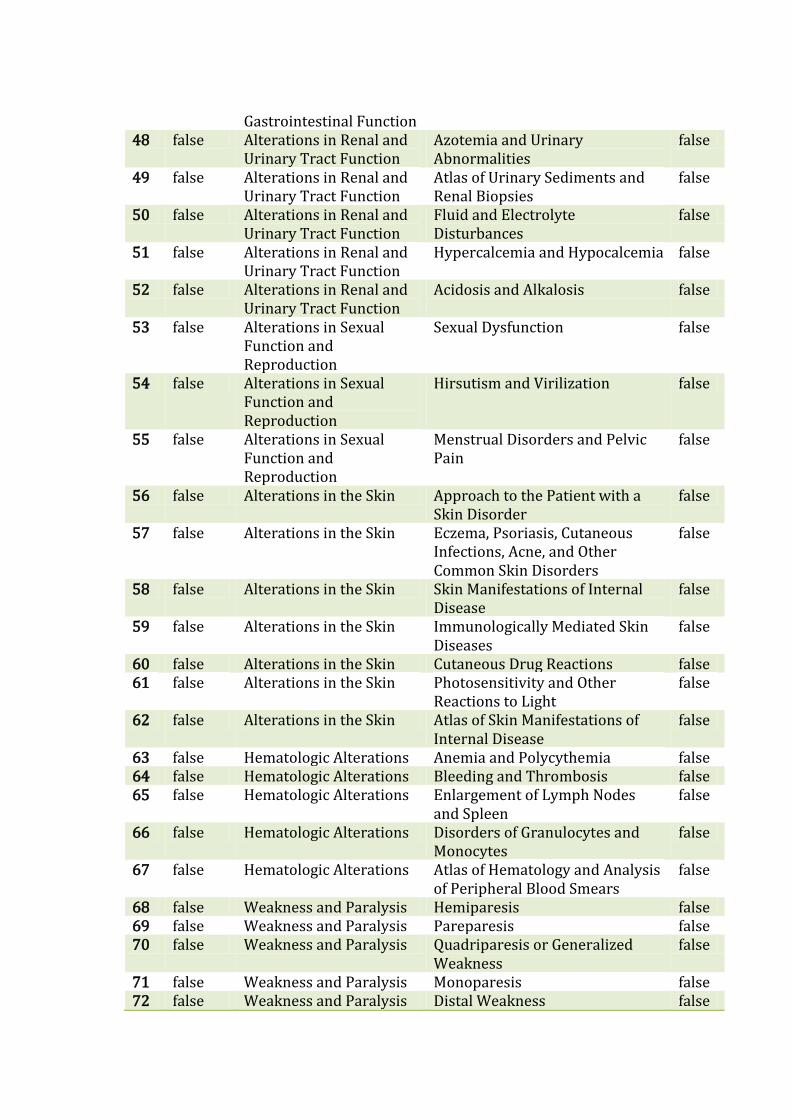
Gastrointestinal Function 48 false Alterations in Renal and
Urinary Tract Function Azotemia and Urinary Abnormalities
false
49 false Alterations in Renal and Urinary Tract Function
Atlas of Urinary Sediments and Renal Biopsies
false
50 false Alterations in Renal and Urinary Tract Function
Fluid and Electrolyte Disturbances
false
51 false Alterations in Renal and Urinary Tract Function
Hypercalcemia and Hypocalcemia false
52 false Alterations in Renal and Urinary Tract Function
Acidosis and Alkalosis false
53 false Alterations in Sexual Function and Reproduction
Sexual Dysfunction false
54 false Alterations in Sexual Function and Reproduction
Hirsutism and Virilization false
55 false Alterations in Sexual Function and Reproduction
Menstrual Disorders and Pelvic Pain
false
56 false Alterations in the Skin Approach to the Patient with a Skin Disorder
false
57 false Alterations in the Skin Eczema, Psoriasis, Cutaneous Infections, Acne, and Other Common Skin Disorders
false
58 false Alterations in the Skin Skin Manifestations of Internal Disease
false
59 false Alterations in the Skin Immunologically Mediated Skin Diseases
false
60 false Alterations in the Skin Cutaneous Drug Reactions false 61 false Alterations in the Skin Photosensitivity and Other
Reactions to Light false
62 false Alterations in the Skin Atlas of Skin Manifestations of Internal Disease
false
63 false Hematologic Alterations Anemia and Polycythemia false 64 false Hematologic Alterations Bleeding and Thrombosis false 65 false Hematologic Alterations Enlargement of Lymph Nodes
and Spleen false
66 false Hematologic Alterations Disorders of Granulocytes and Monocytes
false
67 false Hematologic Alterations Atlas of Hematology and Analysis of Peripheral Blood Smears
false
68 false Weakness and Paralysis Hemiparesis false 69 false Weakness and Paralysis Pareparesis false 70 false Weakness and Paralysis Quadriparesis or Generalized
Weakness false
71 false Weakness and Paralysis Monoparesis false 72 false Weakness and Paralysis Distal Weakness false

73 false Weakness and Paralysis Proximal Weakness false 74 false Weakness and Paralysis Weakness in Restricted
Distribution false
75 false Pareparesis The neurologic history false 76 false Quadriparesis or
Generalized Weakness The neurologic history false
77 false The neurologic history Begin neurologic examination false 78 false Begin neurologic
examination Examine the Motor System of the Limbs and Trunk
false
79 false Begin neurologic examination
Examine the Sensory System of the Limbs and Trunk
false
80 false Begin neurologic examination
Examine Level of Consciuosness false
81 false Begin neurologic examination
Examine Cognitive Function false
82 false Begin neurologic examination
Examine Cranial Nerves false
83 false Begin neurologic examination
Examine Eye Movements and Pupils
false
84 false Begin neurologic examination
Examine Trigeminal Nerve (V) false
85 false Begin neurologic examination
Examine Facial Nerve (V) false
86 false Begin neurologic examination
Examine Vestibulocochlear Nerve (VIII)
false
87 false Begin neurologic examination
Examine Vagus Nerve (X) false
88 false Begin neurologic examination
Examine Glossopharyngeal Nerve (XII)
false
89 false Begin neurologic examination
Examine Hypoglossal Nerve (XII) false
90 false Begin neurologic examination
Examine Accessory Nerve (XI) false
91 false Begin neurologic examination
Examine Stance and Gait false
92 false Begin neurologic examination
Examine Autonomic Nervous System
false
93 false Begin neurologic examination
Skip to next level false
94 false Skip to next level Upper Motor Neuron Signs false 95 false Skip to next level Lower Motor Neuron Signs or
Myopathic Signs false
96 false Upper Motor Neuron Signs
Lesion in Brain false
97 false Upper Motor Neuron Signs
Lesion in Spinal cord false
98 false Lesion in Brain Gradual Onset false 99 false Lesion in Brain Sudden Onset false
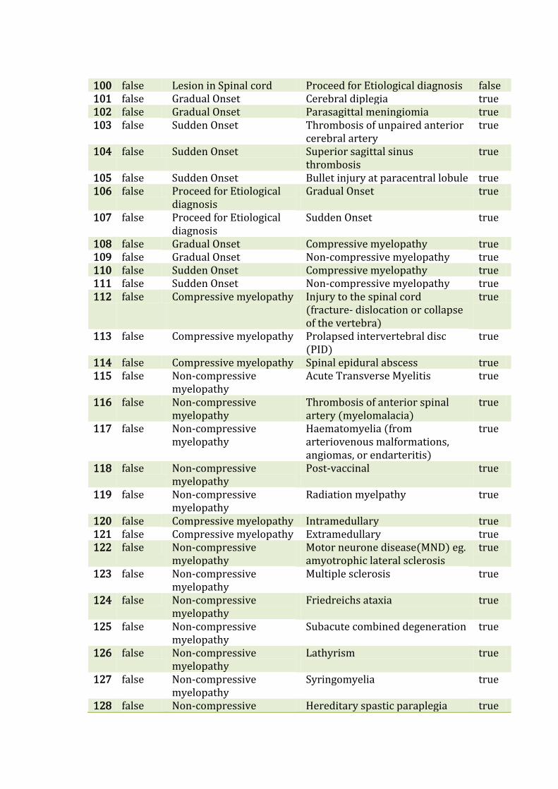
100 false Lesion in Spinal cord Proceed for Etiological diagnosis false 101 false Gradual Onset Cerebral diplegia true 102 false Gradual Onset Parasagittal meningiomia true 103 false Sudden Onset Thrombosis of unpaired anterior
cerebral artery true
104 false Sudden Onset Superior sagittal sinus thrombosis
true
105 false Sudden Onset Bullet injury at paracentral lobule true 106 false Proceed for Etiological
diagnosis Gradual Onset true
107 false Proceed for Etiological diagnosis
Sudden Onset true
108 false Gradual Onset Compressive myelopathy true 109 false Gradual Onset Non-compressive myelopathy true 110 false Sudden Onset Compressive myelopathy true 111 false Sudden Onset Non-compressive myelopathy true 112 false Compressive myelopathy Injury to the spinal cord
(fracture- dislocation or collapse of the vertebra)
true
113 false Compressive myelopathy Prolapsed intervertebral disc (PID)
true
114 false Compressive myelopathy Spinal epidural abscess true 115 false Non-compressive
myelopathy Acute Transverse Myelitis true
116 false Non-compressive myelopathy
Thrombosis of anterior spinal artery (myelomalacia)
true
117 false Non-compressive myelopathy
Haematomyelia (from arteriovenous malformations, angiomas, or endarteritis)
true
118 false Non-compressive myelopathy
Post-vaccinal true
119 false Non-compressive myelopathy
Radiation myelpathy true
120 false Compressive myelopathy Intramedullary true 121 false Compressive myelopathy Extramedullary true 122 false Non-compressive
myelopathy Motor neurone disease(MND) eg. amyotrophic lateral sclerosis
true
123 false Non-compressive myelopathy
Multiple sclerosis true
124 false Non-compressive myelopathy
Friedreichs ataxia true
125 false Non-compressive myelopathy
Subacute combined degeneration true
126 false Non-compressive myelopathy
Lathyrism true
127 false Non-compressive myelopathy
Syringomyelia true
128 false Non-compressive Hereditary spastic paraplegia true

myelopathy 129 false Non-compressive
myelopathy Syphilitic meningomyelitis(rare) false
130 false Non-compressive myelopathy
Tropical spastic paraplegia true
131 false Intramedullary Glioma false 132 false Intramedullary Ependymoma false 133 false Intramedullary Chordoma false 134 false Extramedullary Intradural false 135 false Extramedullary Extradural false 136 false Intradural Meningiomia true 137 false Intradural Neurofibroma true 138 false Intradural Patchy arachnoiditis (tuberclosis,
syphilis) true
139 false Intradural Arteriovenous malformations true 140 false Extradural Caries spine (Plott’s paraplegia) true 141 false Extradural Myeloma, lymphomatous or
metastatic deposits in the vertebra; osteomyelitis
true
142 false Extradural Patchy meningitis true 143 false Extradural Prolapsed intervertebral disc
(PID) true
144 false Extradural Degenerative joint disease (spondylosis)
true
145 false Extradural Fracture or dislocation of the vertebra
true
146 false Extradural Extramedullary haematopoiesis in thalassaemia
true
147 false Extradural Spinal Epidural Abscess true