Embed Size (px)
Citation preview
National Aeronautics and Space Administration
www.nasa.gov 1
Advanced Communications Technologies in
Support of NASA Mission
Dr. Félix A. Miranda
Communications and Intelligent Systems Division
NASA Glenn Research Center, Cleveland, OH 44135
Tel: 216.433.6589
12th European Conference on Antennas and Propagation
ExCeL London, UK
Wednesday, April 11, 2018
https://ntrs.nasa.gov/search.jsp?R=20180004545 2020-03-02T15:37:25+00:00Z
National Aeronautics and Space Administration
www.nasa.gov 2
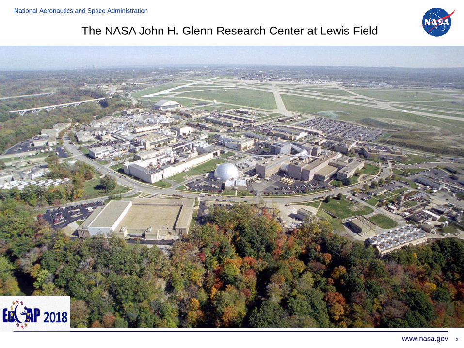
The NASA John H. Glenn Research Center at Lewis Field
National Aeronautics and Space Administration
www.nasa.gov 3
Importance of Communications
Existing and Proposed Communications Networks
Communications Technologies
Communications Technology Development at Glenn
Research Center
Summary
Outline of Presentation
National Aeronautics and Space Administration
www.nasa.gov 444
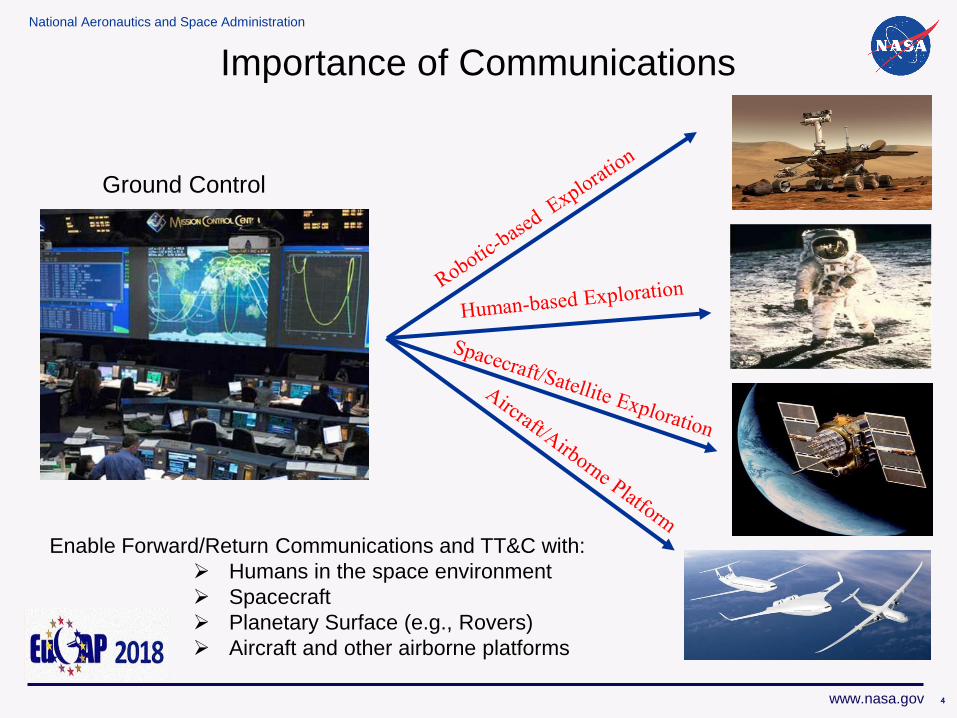
Enable Forward/Return Communications and TT&C with:
Humans in the space environment
Spacecraft
Planetary Surface (e.g., Rovers)
Aircraft and other airborne platforms
Importance of Communications
Ground Control
National Aeronautics and Space Administration
www.nasa.gov 555
Primary Goal in Space to Earth Communications
“Increase Data Rate and Throughput”
National Aeronautics and Space Administration
www.nasa.gov 666
Equ
ival
en
t D
ata
Rat
e (
b/s
) fr
om
Ju
pit
er
(5 A
U)
1012
1010
108
106
104
102
1
10-2
10-4
10-6 Bas
elin
e
3-W
, 1.2
-m S
-Ban
d S
C A
nte
nn
a
Red
uce
d T
ran
spo
nd
er N
ois
e M
aser
10
-W S
-Ban
d T
WT
64
-m D
SN A
nte
nn
aR
edu
ced
Mic
row
ave
No
ise
Red
uce
d A
nt
Surf
To
lera
nce
sIm
pro
ved
DSN
An
ten
na
Inte
rple
xed
, Im
pro
ved
Co
din
g
X-B
and
Mas
erC
on
cate
nat
ed C
od
ing
3.7
-m X
-/X
-Ban
d S
C A
nte
nn
a
Arr
ay: 6
4-m
+ 1
34
-m
Red
uce
d M
icro
wav
e N
ois
e
Vid
eo D
ata
Co
mp
ress
ion
)
64
-m t
o 7
0-m
DSN
An
ten
na
DSN
Arr
ay: 7
0-m
+ 2
34
-m
Imp
rove
d C
od
ing
(15
/1/6
)
Pioneer IV
Mariner IV
Mariner 69 Mariner 10
Voyager
Galileo
1.5
-m S
-/X
-Ban
d A
nte
nn
a
20
-W S
-Ban
d T
WT,
Blo
ck C
od
ing
1950 1960 1970 1980 1990 2000 2010 2020
Op
tica
l Co
mm
un
icat
ion
s
LDP
C C
od
es a
nd
Ad
van
ced
Co
mp
ress
ion
35
W K
a-b
and
Tra
nsm
itte
r
Ka-
Ban
d, D
SN 3
4-m
, SC
3-m
an
ten
nas
Loss
of
Gal
ileo
Co
din
g
KeplerCassini
DSN
Ka-
ban
d A
rray
, 3 x
34
-m
DSN
Ka-
ban
d A
rray
, 7 x
34
-m
R&D OperationalFreq. Life-Cycle =>
S-band
Optical
X-bandKa-band
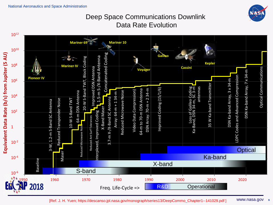
Deep Space Communications Downlink
Data Rate Evolution
[Ref. J. H. Yuen; https://descanso.jpl.nasa.gov/monograph/series13/DeepCommo_Chapter1--141029.pdf ]
National Aeronautics and Space Administration
www.nasa.gov 777
Existing and Proposed
Communications Networks
National Aeronautics and Space Administration
www.nasa.gov 888
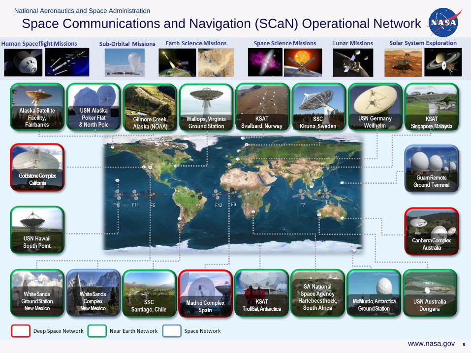
Space Communications and Navigation (SCaN) Operational Network
National Aeronautics and Space Administration
www.nasa.gov
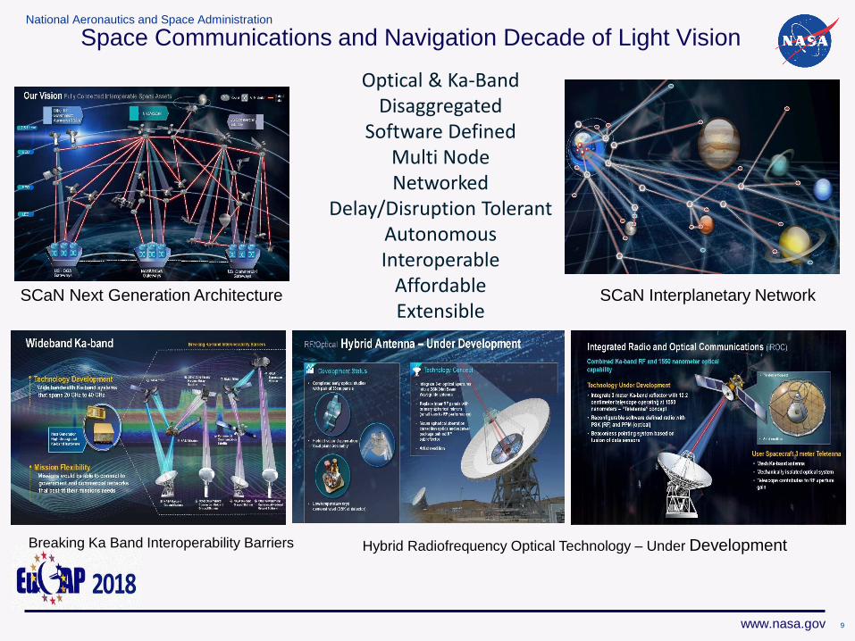
Space Communications and Navigation Decade of Light Vision
Optical & Ka-BandDisaggregated
Software Defined Multi NodeNetworked
Delay/Disruption TolerantAutonomousInteroperable
AffordableExtensible
SCaN Next Generation Architecture SCaN Interplanetary Network
Breaking Ka Band Interoperability Barriers Hybrid Radiofrequency Optical Technology – Under Development
9
National Aeronautics and Space Administration
www.nasa.gov
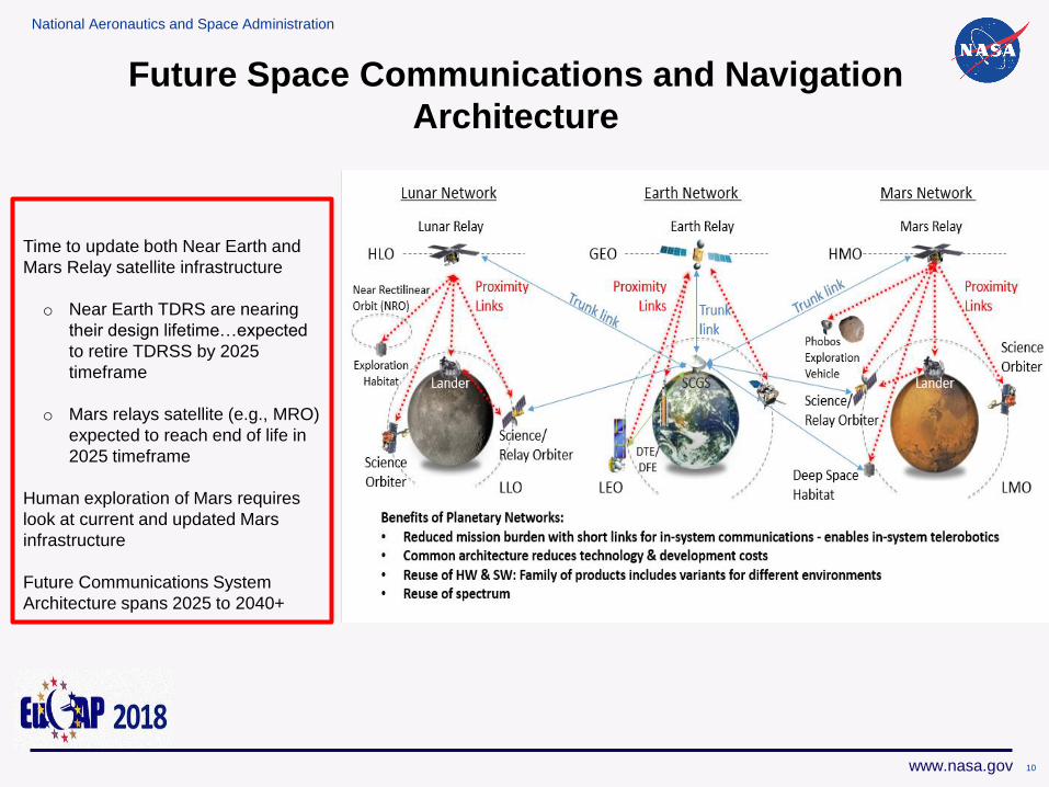
Future Space Communications and Navigation
Architecture
Time to update both Near Earth and
Mars Relay satellite infrastructure
o Near Earth TDRS are nearing
their design lifetime…expected
to retire TDRSS by 2025
timeframe
o Mars relays satellite (e.g., MRO)
expected to reach end of life in
2025 timeframe
Human exploration of Mars requires
look at current and updated Mars
infrastructure
Future Communications System
Architecture spans 2025 to 2040+
10
National Aeronautics and Space Administration
www.nasa.gov 111111
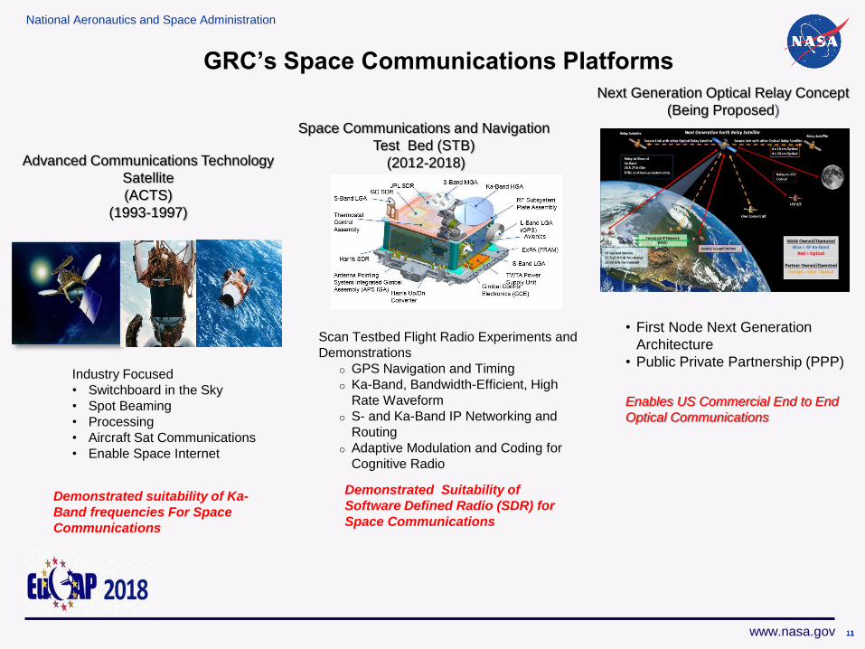
Advanced Communications Technology
Satellite
(ACTS)
(1993-1997)
Scan Testbed Flight Radio Experiments and
Demonstrations
GPS Navigation and Timing
Ka-Band, Bandwidth-Efficient, High
Rate Waveform
S- and Ka-Band IP Networking and
Routing
Adaptive Modulation and Coding for
Cognitive Radio
Space Communications and Navigation
Test Bed (STB)
(2012-2018)
Next Generation Optical Relay Concept
(Being Proposed)
Demonstrated suitability of Ka-
Band frequencies For Space
Communications
Demonstrated Suitability of
Software Defined Radio (SDR) for
Space Communications
Enables US Commercial End to End
Optical Communications
GRC’s Space Communications Platforms
Industry Focused
• Switchboard in the Sky
• Spot Beaming
• Processing
• Aircraft Sat Communications
• Enable Space Internet
• First Node Next Generation
Architecture
• Public Private Partnership (PPP)
National Aeronautics and Space Administration
www.nasa.gov
To enable these Communications Networks
we need Communications Technologies
12
National Aeronautics and Space Administration
www.nasa.gov
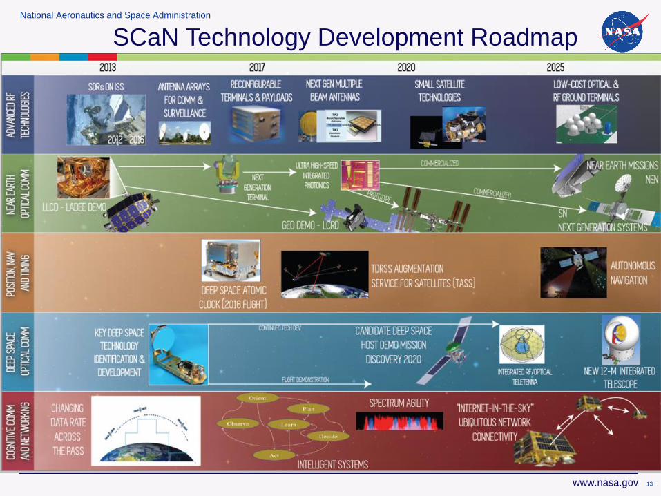
SCaN Technology Development Roadmap
13
National Aeronautics and Space Administration
www.nasa.gov 14
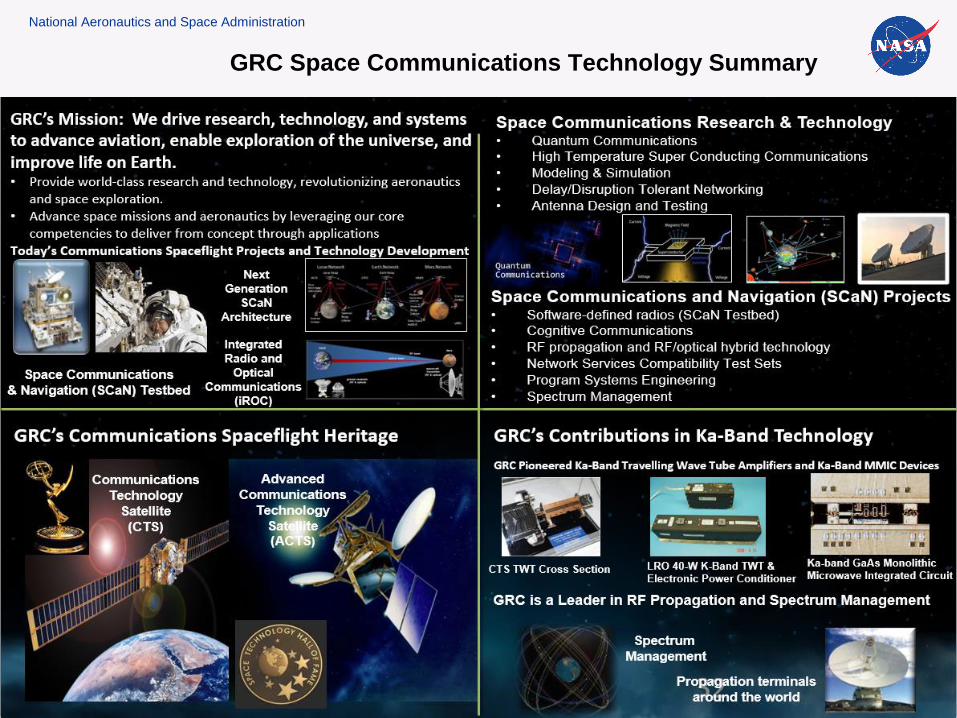
GRC Space Communications Technology Summary
National Aeronautics and Space Administration
www.nasa.gov
RF Communications
Technology
15
National Aeronautics and Space Administration
www.nasa.gov
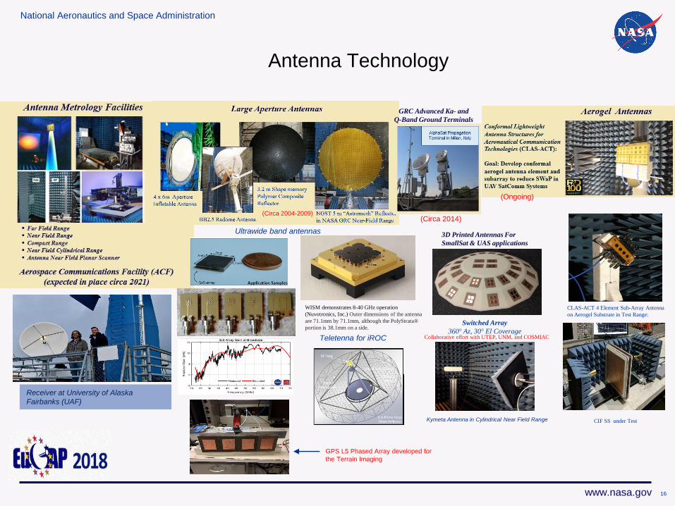
Antenna Technology
(Circa 2004-2009)
GRC Advanced Ka- and
Q-Band Ground Terminals
(Circa 2014)
(Ongoing)
Ultrawide band antennas
WISM demonstrates 8-40 GHz operation
(Nuvotronics, Inc.) Outer dimensions of the antenna
are 71.1mm by 71.1mm, although the PolyStrata®
portion is 38.1mm on a side.
Teletenna for iROC
CLAS-ACT 4 Element Sub-Array Antenna
on Aerogel Substrate in Test Range:
CIF SS under Test
Switched Array
360° Az, 30° El Coverage
3D Printed Antennas For
SmallSat & UAS applications
Collaborative effort with UTEP, UNM, and COSMIAC
Kymeta Antenna in Cylindrical Near Field Range
Receiver at University of Alaska
Fairbanks (UAF)
GPS L5 Phased Array developed for
the Terrain Imaging
16
National Aeronautics and Space Administration
www.nasa.gov
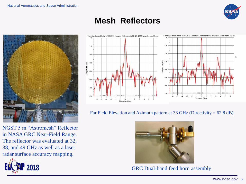
NGST 5 m “Astromesh” Reflector
in NASA GRC Near-Field Range.
The reflector was evaluated at 32,
38, and 49 GHz as well as a laser
radar surface accuracy mapping.
Far Field Elevation and Azimuth pattern at 33 GHz (Directivity = 62.8 dB)
GRC Dual-band feed horn assembly
Mesh Reflectors
17
National Aeronautics and Space Administration
www.nasa.gov
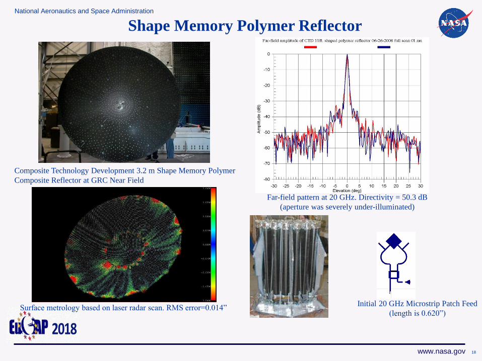
Shape Memory Polymer Reflector
Composite Technology Development 3.2 m Shape Memory Polymer
Composite Reflector at GRC Near Field
Far-field pattern at 20 GHz. Directivity = 50.3 dB
(aperture was severely under-illuminated)
Initial 20 GHz Microstrip Patch Feed
(length is 0.620”)Surface metrology based on laser radar scan. RMS error=0.014”
18
National Aeronautics and Space Administration
www.nasa.gov
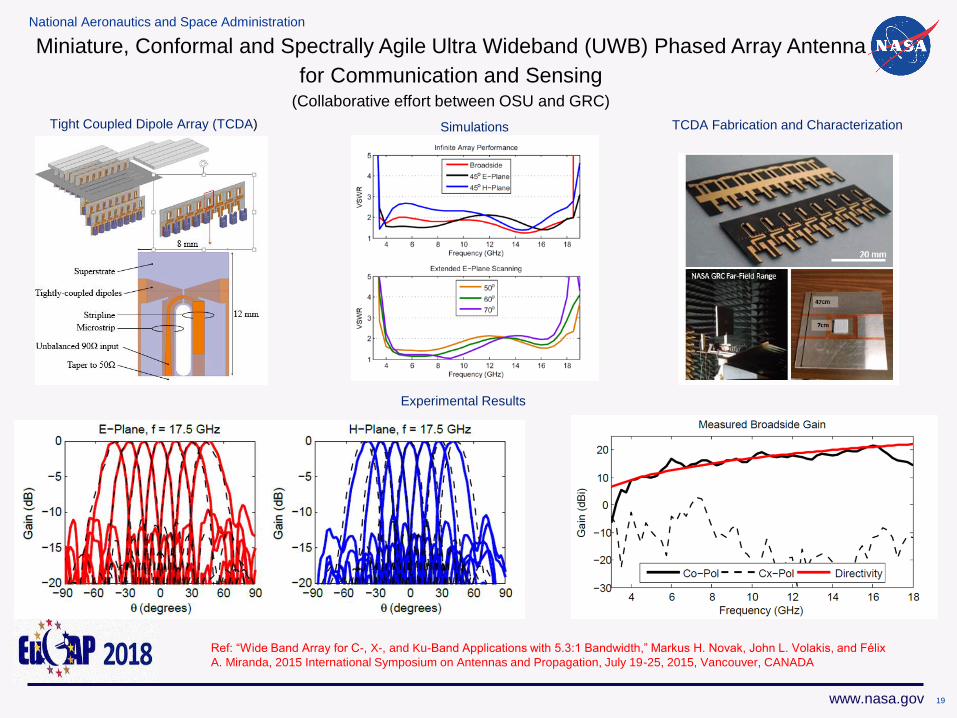
Tight Coupled Dipole Array (TCDA) Simulations TCDA Fabrication and Characterization
Experimental Results
Ref: “Wide Band Array for C-, X-, and Ku-Band Applications with 5.3:1 Bandwidth,” Markus H. Novak, John L. Volakis, and Félix
A. Miranda, 2015 International Symposium on Antennas and Propagation, July 19-25, 2015, Vancouver, CANADA
Miniature, Conformal and Spectrally Agile Ultra Wideband (UWB) Phased Array Antenna
for Communication and Sensing(Collaborative effort between OSU and GRC)
19
National Aeronautics and Space Administration
www.nasa.gov
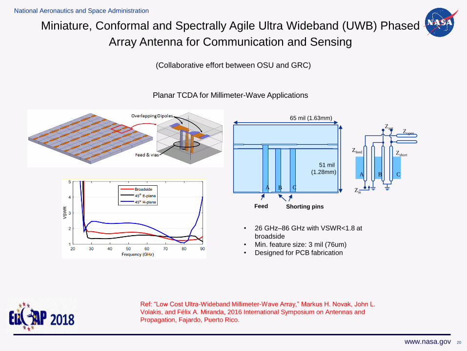
Planar TCDA for Millimeter-Wave Applications
A B C
Zfeed Zshort
Zant
Zin
A B C
Zopen
• 26 GHz–86 GHz with VSWR<1.8 at
broadside
• Min. feature size: 3 mil (76um)
• Designed for PCB fabrication
Feed Shorting pins
65 mil (1.63mm)
51 mil
(1.28mm)
Ref: “Low Cost Ultra-Wideband Millimeter-Wave Array,” Markus H. Novak, John L.
Volakis, and Félix A. Miranda, 2016 International Symposium on Antennas and
Propagation, Fajardo, Puerto Rico.
Miniature, Conformal and Spectrally Agile Ultra Wideband (UWB) Phased
Array Antenna for Communication and Sensing
(Collaborative effort between OSU and GRC)
20
National Aeronautics and Space Administration
www.nasa.gov
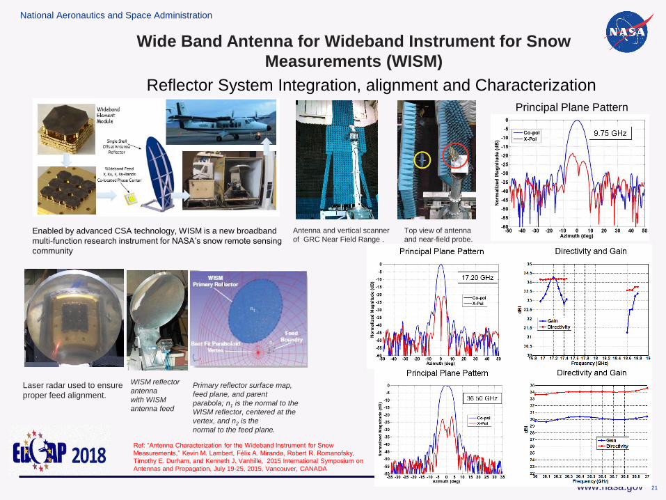
Reflector System Integration, alignment and Characterization
Wide Band Antenna for Wideband Instrument for Snow
Measurements (WISM)
Enabled by advanced CSA technology, WISM is a new broadband
multi-function research instrument for NASA’s snow remote sensing
community
Laser radar used to ensure
proper feed alignment.
WISM reflector
antenna
with WISM
antenna feed
Primary reflector surface map,
feed plane, and parent
parabola; n1 is the normal to the
WISM reflector, centered at the
vertex, and n2 is the
normal to the feed plane.
Antenna and vertical scanner
of GRC Near Field Range .
Top view of antenna
and near-field probe.
Principal Plane Pattern
Ref: “Antenna Characterization for the Wideband Instrument for Snow
Measurements,” Kevin M. Lambert, Félix A. Miranda, Robert R. Romanofsky,
Timothy E. Durham, and Kenneth J. Vanhille, 2015 International Symposium on
Antennas and Propagation, July 19-25, 2015, Vancouver, CANADA
21
National Aeronautics and Space Administration
www.nasa.gov
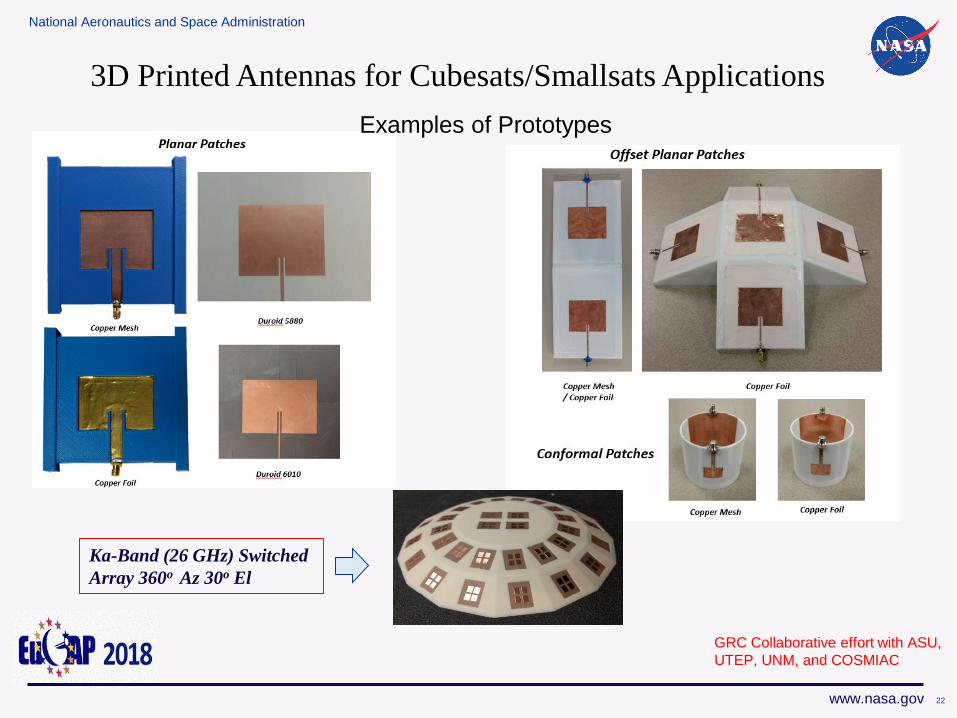
Examples of Prototypes
GRC Collaborative effort with ASU,
UTEP, UNM, and COSMIAC
3D Printed Antennas for Cubesats/Smallsats Applications
22
Ka-Band (26 GHz) Switched
Array 360o Az 30o El
National Aeronautics and Space Administration
www.nasa.gov
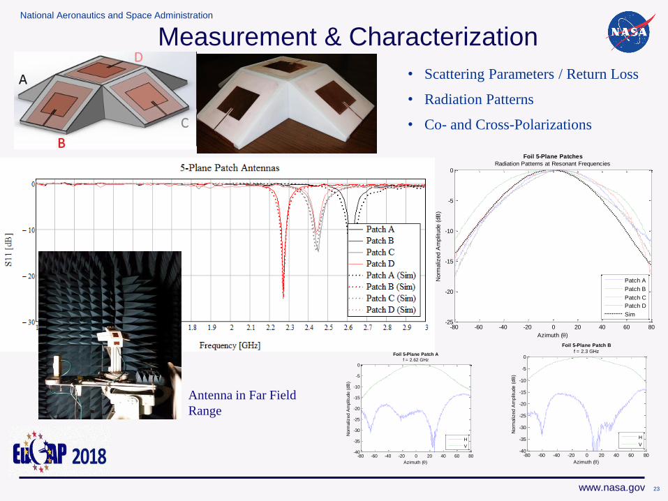
Measurement & Characterization
• Scattering Parameters / Return Loss
• Radiation Patterns
• Co- and Cross-Polarizations
-80 -60 -40 -20 0 20 40 60 80-25
-20
-15
-10
-5
0
Foil 5-Plane Patches
Radiation Patterns at Resonant Frequencies
Azimuth ()
Norm
aliz
ed A
mplit
ude (
dB
)
Patch A
Patch B
Patch C
Patch D
Sim
-80 -60 -40 -20 0 20 40 60 80-40
-35
-30
-25
-20
-15
-10
-5
0
Foil 5-Plane Patch A
f = 2.62 GHz
Azimuth ()
Norm
aliz
ed A
mplit
ude (
dB
)
H
V
-80 -60 -40 -20 0 20 40 60 80-40
-35
-30
-25
-20
-15
-10
-5
0
Foil 5-Plane Patch B
f = 2.3 GHz
Azimuth ()
Norm
aliz
ed A
mplit
ude (
dB
)
H
V
23
Antenna in Far Field
Range
National Aeronautics and Space Administration
www.nasa.gov
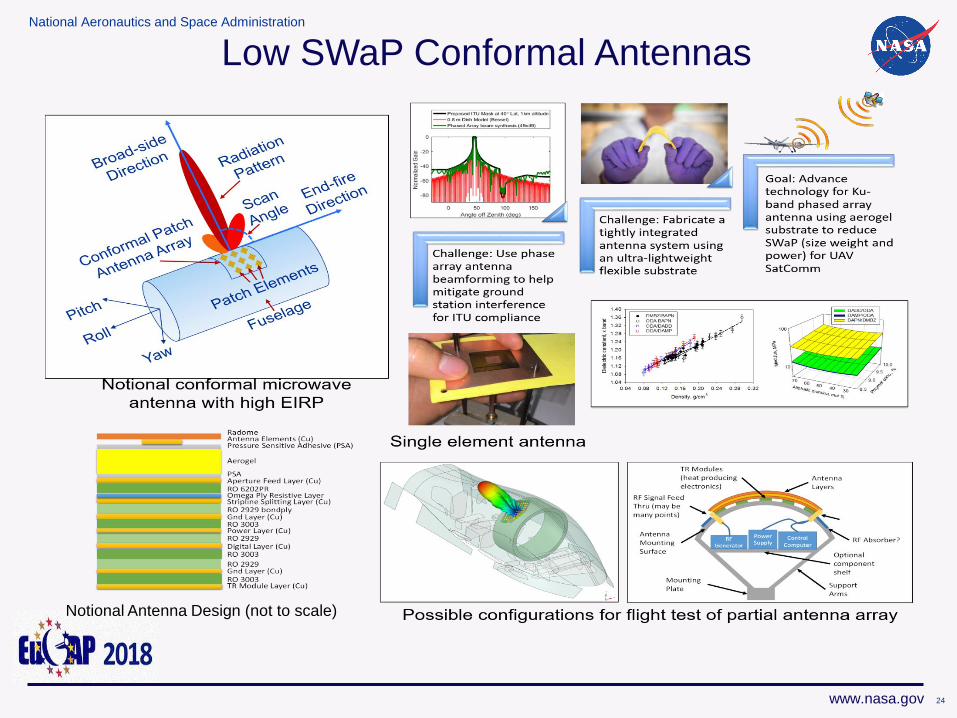
Notional Antenna Design (not to scale)
Low SWaP Conformal Antennas
24
National Aeronautics and Space Administration
www.nasa.gov
Power Amplifiers
25
National Aeronautics and Space Administration
www.nasa.gov
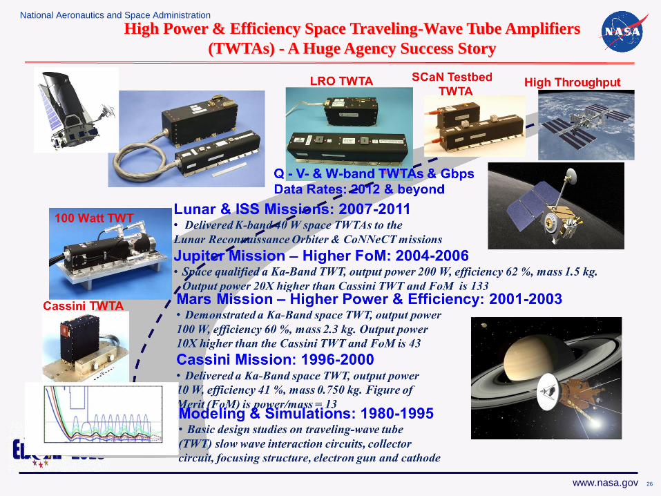
High Power & Efficiency Space Traveling-Wave Tube Amplifiers
(TWTAs) - A Huge Agency Success Story
26
National Aeronautics and Space Administration
www.nasa.gov
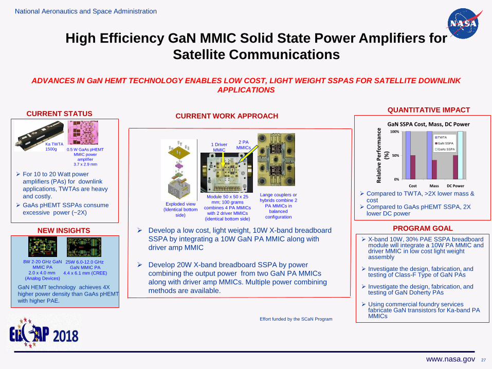
High Efficiency GaN MMIC Solid State Power Amplifiers for
Satellite Communications
NEW INSIGHTS
For 10 to 20 Watt power
amplifiers (PAs) for downlink
applications, TWTAs are heavy
and costly.
GaAs pHEMT SSPAs consume
excessive power (~2X)
CURRENT STATUS
ADVANCES IN GaN HEMT TECHNOLOGY ENABLES LOW COST, LIGHT WEIGHT SSPAS FOR SATELLITE DOWNLINK
APPLICATIONS
CURRENT WORK APPROACHQUANTITATIVE IMPACT
Compared to TWTA, >2X lower mass & cost
Compared to GaAs pHEMT SSPA, 2X lower DC power
PROGRAM GOAL
X-band 10W, 30% PAE SSPA breadboard module will integrate a 10W PA MMIC and driver MMIC in low cost light weight assembly
Investigate the design, fabrication, and testing of Class-F Type of GaN PAs
Investigate the design, fabrication, and testing of GaN Doherty PAs
Using commercial foundry services fabricate GaN transistors for Ka-band PA MMICs
Ka TWTA
1500g 0.5 W GaAs pHEMT
MMIC power
amplifier
3.7 x 2.9 mm
8W 2-20 GHz GaN
MMIC PA
2.0 x 4.0 mm
(Analog Devices)
25W 6.0-12.0 GHz
GaN MMIC PA
4.4 x 6.1 mm (CREE)
GaN HEMT technology achieves 4X
higher power density than GaAs pHEMT
with higher PAE.
Module 50 x 50 x 25
mm; 100 grams
combines 4 PA MMICs
with 2 driver MMICs
(identical bottom side)
Exploded view
(Identical bottom
side)
Lange couplers or
hybrids combine 2
PA MMICs in
balanced
configuration
2 PA
MMICs1 Driver
MMIC
Develop a low cost, light weight, 10W X-band breadboard
SSPA by integrating a 10W GaN PA MMIC along with
driver amp MMIC
Develop 20W X-band breadboard SSPA by power
combining the output power from two GaN PA MMICs
along with driver amp MMICs. Multiple power combining
methods are available.
GaN SSPA Cost, Mass, DC Power
0%
50%
100%
Cost Mass DC Power
Re
lati
ve P
erf
orm
ance
(%)
TWTA
GaN SSPA
GaAs SSPA
Effort funded by the SCaN Program
27
National Aeronautics and Space Administration
www.nasa.gov 2828
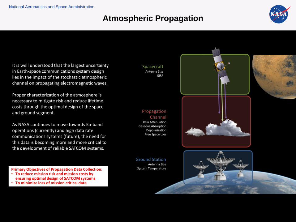
Ground StationAntenna Size
System Temperature
SpacecraftAntenna Size
EIRP
Propagation Channel
Rain AttenuationGaseous Absorption
DepolarizationFree Space Loss
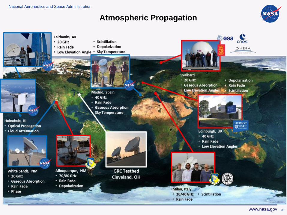
It is well understood that the largest uncertainty in Earth-space communications system design lies in the impact of the stochastic atmospheric channel on propagating electromagnetic waves.
Proper characterization of the atmosphere is necessary to mitigate risk and reduce lifetime costs through the optimal design of the space and ground segment.
As NASA continues to move towards Ka-band operations (currently) and high data rate communications systems (future), the need for this data is becoming more and more critical to the development of reliable SATCOM systems.
28
Primary Objectives of Propagation Data Collection: • To reduce mission risk and mission costs by
ensuring optimal design of SATCOM systems• To minimize loss of mission critical data
Atmospheric Propagation
National Aeronautics and Space Administration
www.nasa.gov
Atmospheric Propagation
29
National Aeronautics and Space Administration
www.nasa.gov
Software Defined Radio and
Cognitive Communications
30
National Aeronautics and Space Administration
www.nasa.gov
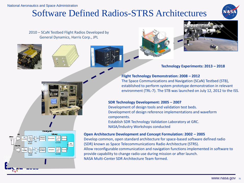
2010 – SCaN Testbed Flight Radios Developed by General Dynamics, Harris Corp., JPL
Flight Technology Demonstration: 2008 – 2012The Space Communications and Navigation (SCaN) Testbed (STB), established to perform system prototype demonstration in relevant environment (TRL-7). The STB was launched on July 12, 2012 to the ISS.
Open Architecture Development and Concept Formulation: 2002 – 2005Develop common, open standard architecture for space-based software defined radio (SDR) known as Space Telecommunications Radio Architecture (STRS). Allow reconfigurable communication and navigation functions implemented in software to provide capability to change radio use during mission or after launch.NASA Multi-Center SDR Architecture Team formed.
SDR Technology Development: 2005 – 2007Development of design tools and validation test beds. Development of design reference implementations and waveform components.Establish SDR Technology Validation Laboratory at GRC. NASA/Industry Workshops conducted
Technology Experiments: 2013 – 2018
Software Defined Radios-STRS Architectures
31
National Aeronautics and Space Administration
www.nasa.gov
Advancing the SOA in Software Defined Radios
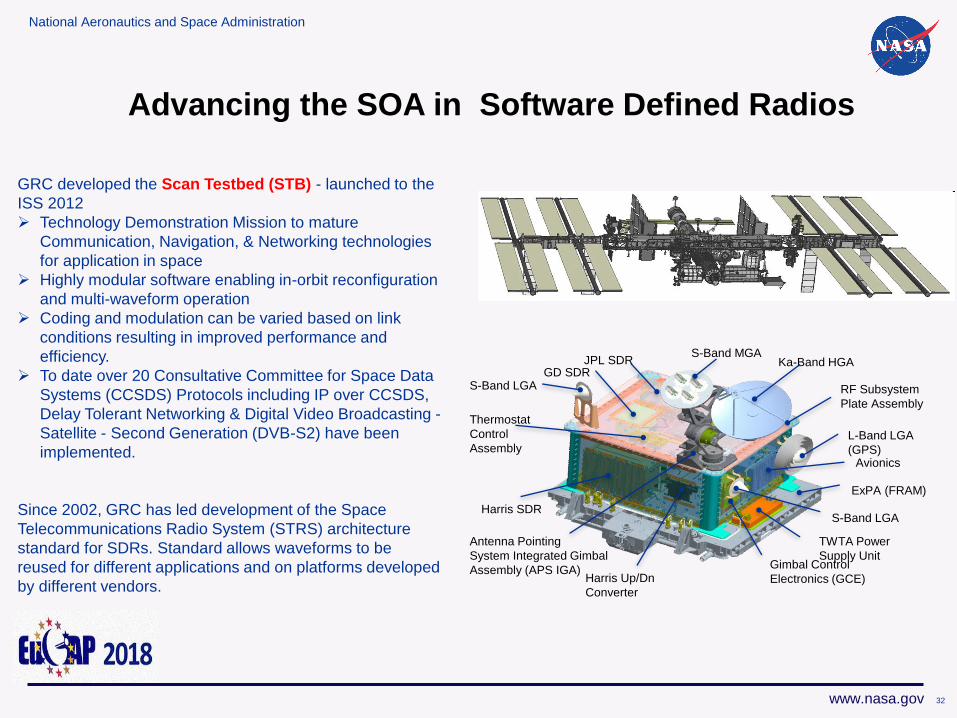
GRC developed the Scan Testbed (STB) - launched to the
ISS 2012
Technology Demonstration Mission to mature
Communication, Navigation, & Networking technologies
for application in space
Highly modular software enabling in-orbit reconfiguration
and multi-waveform operation
Coding and modulation can be varied based on link
conditions resulting in improved performance and
efficiency.
To date over 20 Consultative Committee for Space Data
Systems (CCSDS) Protocols including IP over CCSDS,
Delay Tolerant Networking & Digital Video Broadcasting -
Satellite - Second Generation (DVB-S2) have been
implemented.
Since 2002, GRC has led development of the Space
Telecommunications Radio System (STRS) architecture
standard for SDRs. Standard allows waveforms to be
reused for different applications and on platforms developed
by different vendors.
Ka-Band HGAJPL SDR
Antenna Pointing
System Integrated Gimbal
Assembly (APS IGA) Gimbal Control
Electronics (GCE)
L-Band LGA
(GPS)
S-Band MGA
GD SDRS-Band LGA
Thermostat
Control
Assembly
Harris SDR
Harris Up/Dn
Converter
ExPA (FRAM)
Avionics
S-Band LGA
TWTA Power
Supply Unit
RF Subsystem
Plate Assembly
32
National Aeronautics and Space Administration
www.nasa.gov
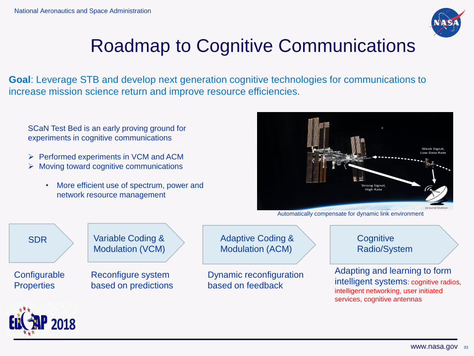
Roadmap to Cognitive Communications
Ground Station
Weak Signal, Low Data Rate
Strong Signal, High Rate
Goal: Leverage STB and develop next generation cognitive technologies for communications to
increase mission science return and improve resource efficiencies.
SCaN Test Bed is an early proving ground for
experiments in cognitive communications
Performed experiments in VCM and ACM
Moving toward cognitive communications
• More efficient use of spectrum, power and
network resource management
SDR Variable Coding &
Modulation (VCM)
Adaptive Coding &
Modulation (ACM)
Cognitive
Radio/System
Configurable
Properties
Reconfigure system
based on predictions
Dynamic reconfiguration
based on feedback
Adapting and learning to form
intelligent systems: cognitive radios,
intelligent networking, user initiated
services, cognitive antennas
Automatically compensate for dynamic link environment
33
National Aeronautics and Space Administration
www.nasa.gov
Optical Communications
34
National Aeronautics and Space Administration
www.nasa.gov
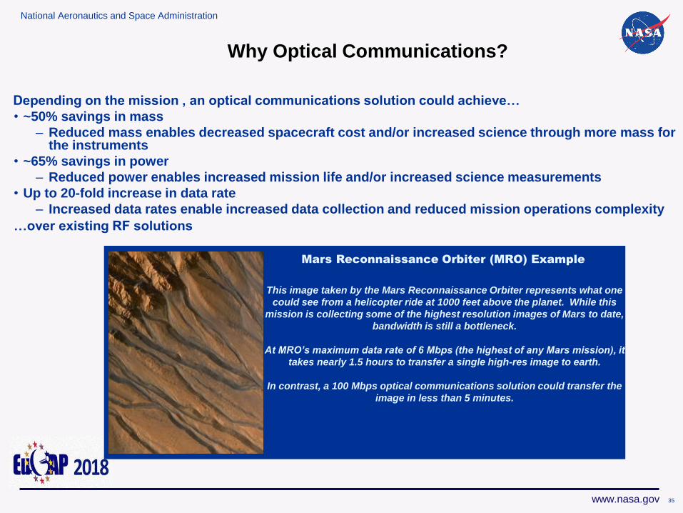
Depending on the mission , an optical communications solution could achieve…
• ~50% savings in mass
– Reduced mass enables decreased spacecraft cost and/or increased science through more mass for the instruments
• ~65% savings in power
– Reduced power enables increased mission life and/or increased science measurements
• Up to 20-fold increase in data rate
– Increased data rates enable increased data collection and reduced mission operations complexity
…over existing RF solutions
Mars Reconnaissance Orbiter
This image taken by the Mars Reconnaissance Orbiter represents what one
could see from a helicopter ride at 1000 feet above the planet. While this
mission is collecting some of the highest resolution images of Mars to date,
bandwidth is still a bottleneck.
At MRO’s maximum data rate of 6 Mbps (the highest of any Mars mission), it
takes nearly 1.5 hours to transfer a single high-res image to earth.
In contrast, a 100 Mbps optical communications solution could transfer the
image in less than 5 minutes.
Mars Reconnaissance Orbiter (MRO) Example
Why Optical Communications?
35
36
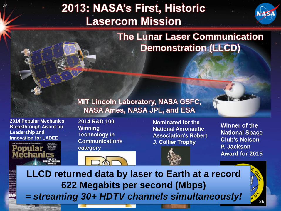
2014 R&D 100
Winning
Technology in
Communications
category
2014 Popular Mechanics
Breakthrough Award for
Leadership and
Innovation for LADEE
Nominated for the
National Aeronautic
Association's Robert
J. Collier Trophy
Winner of the
National Space
Club’s Nelson
P. Jackson
Award for 2015
2013: NASA’s First, Historic
Lasercom Mission
The Lunar Laser Communication
Demonstration (LLCD)
MIT Lincoln Laboratory, NASA GSFC,
NASA Ames, NASA JPL, and ESA
LLCD returned data by laser to Earth at a record
622 Megabits per second (Mbps)
= streaming 30+ HDTV channels simultaneously!36
37 37
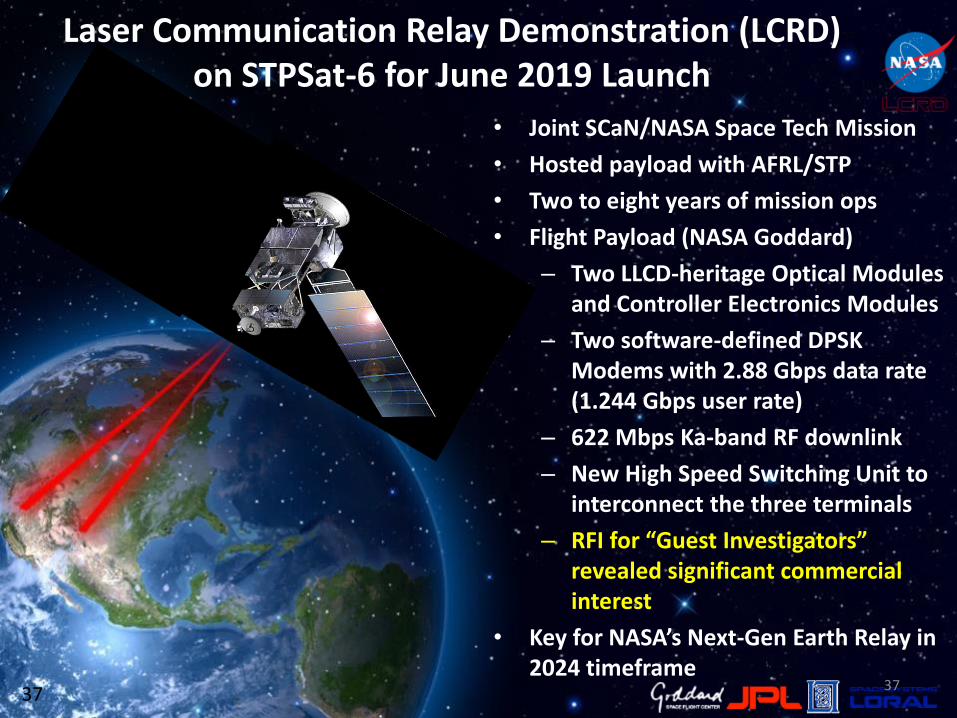
• Joint SCaN/NASA Space Tech Mission
• Hosted payload with AFRL/STP
• Two to eight years of mission ops
• Flight Payload (NASA Goddard)
– Two LLCD-heritage Optical Modules and Controller Electronics Modules
– Two software-defined DPSK Modems with 2.88 Gbps data rate (1.244 Gbps user rate)
– 622 Mbps Ka-band RF downlink
– New High Speed Switching Unit to interconnect the three terminals
– RFI for “Guest Investigators” revealed significant commercial interest
• Key for NASA’s Next-Gen Earth Relay in 2024 timeframe
Laser Communication Relay Demonstration (LCRD) on STPSat-6 for June 2019 Launch
National Aeronautics and Space Administration
www.nasa.gov
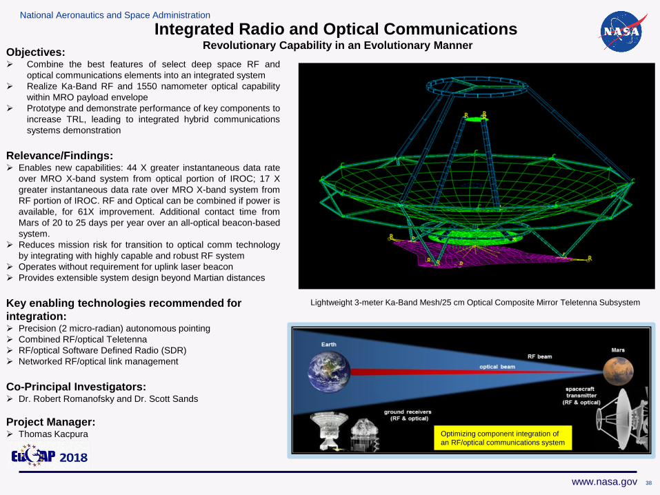
Integrated Radio and Optical CommunicationsRevolutionary Capability in an Evolutionary Manner
Objectives: Combine the best features of select deep space RF and
optical communications elements into an integrated system
Realize Ka-Band RF and 1550 namometer optical capability
within MRO payload envelope
Prototype and demonstrate performance of key components to
increase TRL, leading to integrated hybrid communications
systems demonstration
Relevance/Findings: Enables new capabilities: 44 X greater instantaneous data rate
over MRO X-band system from optical portion of IROC; 17 X
greater instantaneous data rate over MRO X-band system from
RF portion of IROC. RF and Optical can be combined if power is
available, for 61X improvement. Additional contact time from
Mars of 20 to 25 days per year over an all-optical beacon-based
system.
Reduces mission risk for transition to optical comm technology
by integrating with highly capable and robust RF system
Operates without requirement for uplink laser beacon
Provides extensible system design beyond Martian distances
Key enabling technologies recommended for
integration: Precision (2 micro-radian) autonomous pointing
Combined RF/optical Teletenna
RF/optical Software Defined Radio (SDR)
Networked RF/optical link management
Co-Principal Investigators: Dr. Robert Romanofsky and Dr. Scott Sands
Project Manager: Thomas Kacpura
Lightweight 3-meter Ka-Band Mesh/25 cm Optical Composite Mirror Teletenna Subsystem
Optimizing component integration of
an RF/optical communications system
38
National Aeronautics and Space Administration
www.nasa.gov
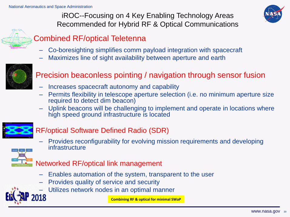
Combined RF/optical Teletenna
– Co-boresighting simplifies comm payload integration with spacecraft
– Maximizes line of sight availability between aperture and earth
• Precision beaconless pointing / navigation through sensor fusion
– Increases spacecraft autonomy and capability
– Permits flexibility in telescope aperture selection (i.e. no minimum aperture size required to detect dim beacon)
– Uplink beacons will be challenging to implement and operate in locations where high speed ground infrastructure is located
• RF/optical Software Defined Radio (SDR)
– Provides reconfigurability for evolving mission requirements and developing infrastructure
• Networked RF/optical link management
– Enables automation of the system, transparent to the user
– Provides quality of service and security
– Utilizes network nodes in an optimal manner
Combining RF & optical for minimal SWaP
iROC--Focusing on 4 Key Enabling Technology Areas
Recommended for Hybrid RF & Optical Communications
39
National Aeronautics and Space Administration
www.nasa.gov 40
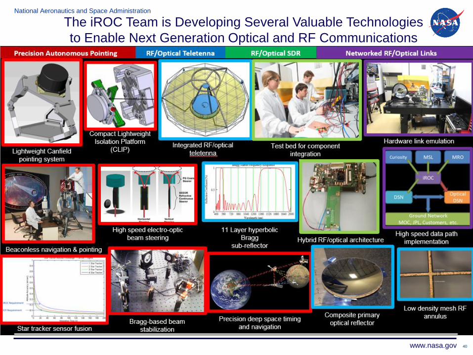
The iROC Team is Developing Several Valuable Technologies
to Enable Next Generation Optical and RF Communications
National Aeronautics and Space Administration
www.nasa.gov
Disruptive Technologies
41
National Aeronautics and Space Administration
www.nasa.gov
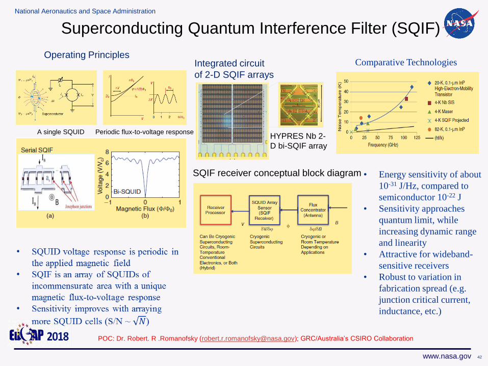
Integrated circuit
of 2-D SQIF arrays
Operating Principles
HYPRES Nb 2-
D bi-SQIF array
SQIF receiver conceptual block diagram
Comparative Technologies
• Energy sensitivity of about
10-31 J/Hz, compared to
semiconductor 10-22 J
• Sensitivity approaches
quantum limit, while
increasing dynamic range
and linearity
• Attractive for wideband-
sensitive receivers
• Robust to variation in
fabrication spread (e.g.
junction critical current,
inductance, etc.)
A single SQUID Periodic flux-to-voltage response
Superconducting Quantum Interference Filter (SQIF)
POC: Dr. Robert. R .Romanofsky ([email protected]); GRC/Australia’s CSIRO Collaboration
42
National Aeronautics and Space Administration
www.nasa.gov
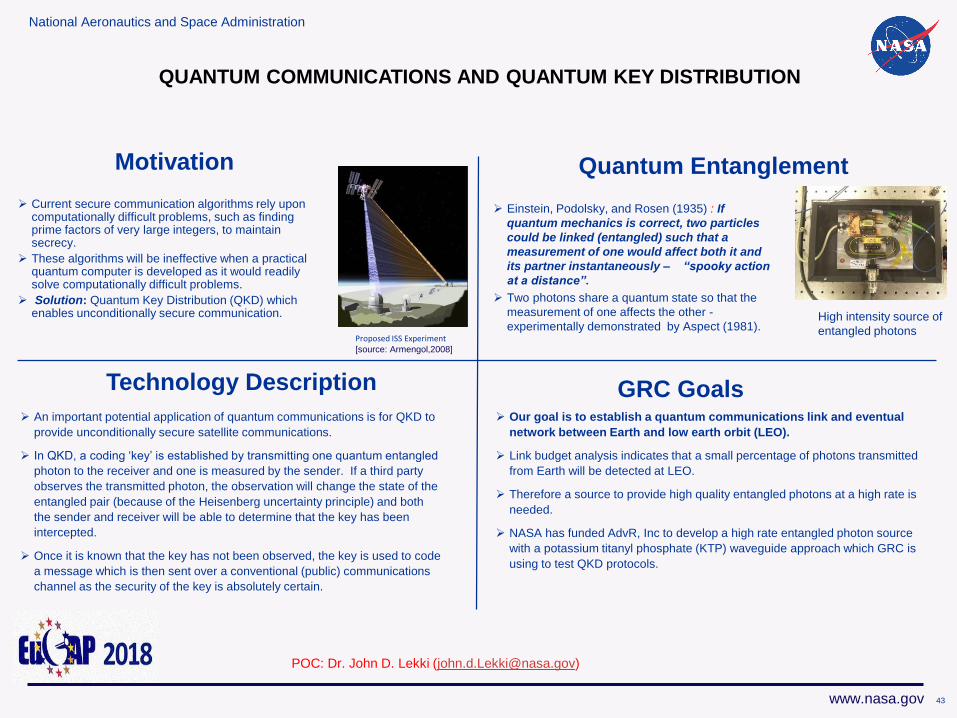
QUANTUM COMMUNICATIONS AND QUANTUM KEY DISTRIBUTION
Current secure communication algorithms rely upon computationally difficult problems, such as finding prime factors of very large integers, to maintain secrecy.
These algorithms will be ineffective when a practical quantum computer is developed as it would readily solve computationally difficult problems.
Solution: Quantum Key Distribution (QKD) which enables unconditionally secure communication.
Motivation Quantum Entanglement
Einstein, Podolsky, and Rosen (1935) : If
quantum mechanics is correct, two particles
could be linked (entangled) such that a
measurement of one would affect both it and
its partner instantaneously – “spooky action
at a distance”.
Two photons share a quantum state so that the
measurement of one affects the other -
experimentally demonstrated by Aspect (1981).
An important potential application of quantum communications is for QKD to
provide unconditionally secure satellite communications.
In QKD, a coding ‘key’ is established by transmitting one quantum entangled
photon to the receiver and one is measured by the sender. If a third party
observes the transmitted photon, the observation will change the state of the
entangled pair (because of the Heisenberg uncertainty principle) and both
the sender and receiver will be able to determine that the key has been
intercepted.
Once it is known that the key has not been observed, the key is used to code
a message which is then sent over a conventional (public) communications
channel as the security of the key is absolutely certain.
Technology Description
Our goal is to establish a quantum communications link and eventual
network between Earth and low earth orbit (LEO).
Link budget analysis indicates that a small percentage of photons transmitted
from Earth will be detected at LEO.
Therefore a source to provide high quality entangled photons at a high rate is
needed.
NASA has funded AdvR, Inc to develop a high rate entangled photon source
with a potassium titanyl phosphate (KTP) waveguide approach which GRC is
using to test QKD protocols.
GRC Goals
Proposed ISS Experiment [source: Armengol,2008]
High intensity source of
entangled photons
POC: Dr. John D. Lekki ([email protected])
43
National Aeronautics and Space Administration
www.nasa.gov
Summary
The specific communications technologies needed for future NASA exploration missions
to ensure full availability of deep space science mission data returns will depend on:
Data rate requirements, available frequencies, available space and power, and
desired asset-specific services. Likewise, efficiency, power, mass, and cost will drive
decisions.
As the RF spectrum becomes increasingly congested there is a need to move to
higher frequencies (e.g., upper Ka-Band and 5G) and to develop technologies (e.g.,
cognitive radios, cognitive antennas, memristors, etc.) as well as algorithms to enable
cognitive communications systems resulting on efficient spectrum utilization.
The optical spectrum is essentially wide open and we are in the midst of “Decade of
Light” where new space communications architectures will have optical
communications as an integral part.
44
National Aeronautics and Space Administration
www.nasa.gov 4545
Acknowledgements
NASA
HEOMD SCaN Project Office
ARMD Convergent Aeronautics
Solutions
GRC’s Communications
and Intelligent Systems Division
Academia
The Ohio State University (OSU)
Prof. John Volakis (Now with FIU)
Markus Novak
University of Texas El Paso
Prof. Eric MacDonald (currently at
Youngstown State)
University of New Mexico
Prof. Christos Christodoulou
COSMIAC
Mr. Craig Kief