Embed Size (px)
DESCRIPTION
Advanced Computer Networks. Background Material 1: Getting stuff from here to there Acknowledgments: Lecture slides are from the graduate level Computer Networks course thought by Srinivasan Seshan at CMU. When slides are - PowerPoint PPT Presentation
Citation preview
Advanced Computer Networks
Background Material 1: Getting stuff from here to there
Acknowledgments: Lecture slides are from the graduate level ComputerNetworks course thought by Srinivasan Seshan at CMU. When slides areobtained from other sources, a reference will be noted on the bottom of
that slide.
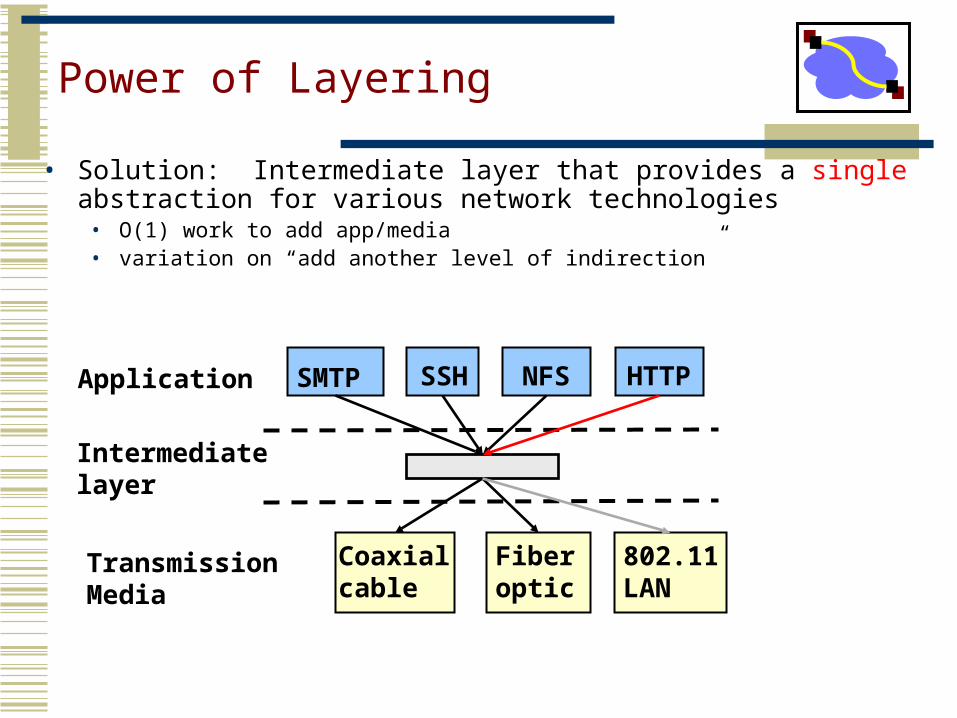
Power of Layering
• Solution: Intermediate layer that provides a single abstraction for various network technologies
• O(1) work to add app/media• variation on “add another level of indirection”
SMTP SSH NFS
802.11LAN
Coaxial cable
Fiberoptic
Application
TransmissionMedia
HTTP
Intermediate layer
Outline
• Switching and Multiplexing
• Link-Layer
• Routing-Layer
• Physical-Layer Encoding
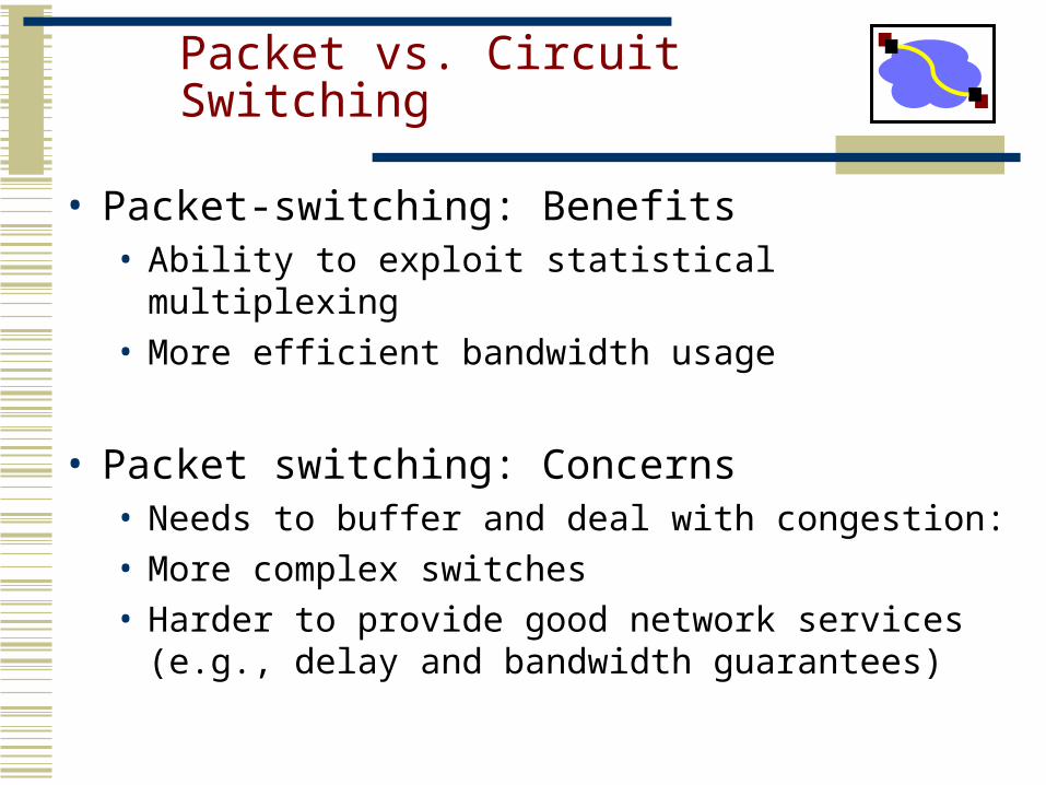
Packet vs. Circuit Switching
• Packet-switching: Benefits• Ability to exploit statistical multiplexing• More efficient bandwidth usage
• Packet switching: Concerns • Needs to buffer and deal with congestion:• More complex switches• Harder to provide good network services (e.g., delay
and bandwidth guarantees)
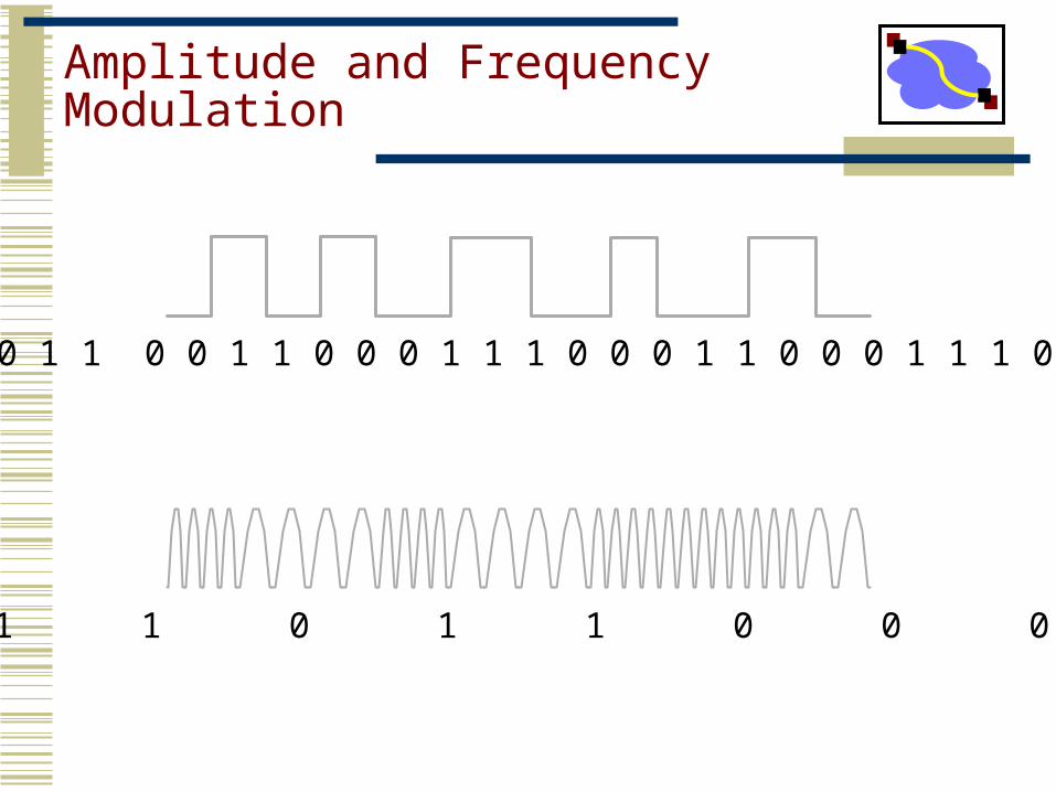
Amplitude and FrequencyModulation
0 0 1 1 0 0 1 1 0 0 0 1 1 1 0 0 0 1 1 0 0 0 1 1 1 0
0 1 1 0 1 1 0 0 0 1
Capacity of a Noisy Channel
• Can’t add infinite symbols - you have to be able to tell them apart. This is where noise comes in.
• Shannon’s theorem:• C = B x log(1 + S/N)• C: maximum capacity (bps)• B: channel bandwidth (Hz)• S/N: signal to noise ratio of the channel
• Often expressed in decibels (db). 10 log(S/N).• Example:
• Local loop bandwidth: 3200 Hz• Typical S/N: 1000 (30db)• What is the upper limit on capacity?
• Modems: Teleco internally converts to 56kbit/s digital signal, which sets a limit on B and the S/N.
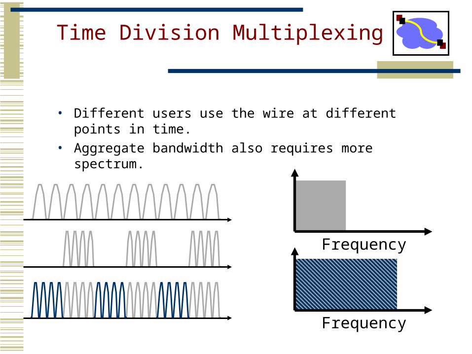
Time Division Multiplexing
• Different users use the wire at different points in time.• Aggregate bandwidth also requires more spectrum.
Frequency
Frequency
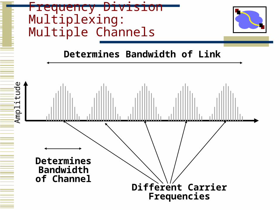
Frequency Division Multiplexing:Multiple Channels
Am
plitu
de
Different CarrierFrequencies
DeterminesBandwidthof Channel
Determines Bandwidth of Link
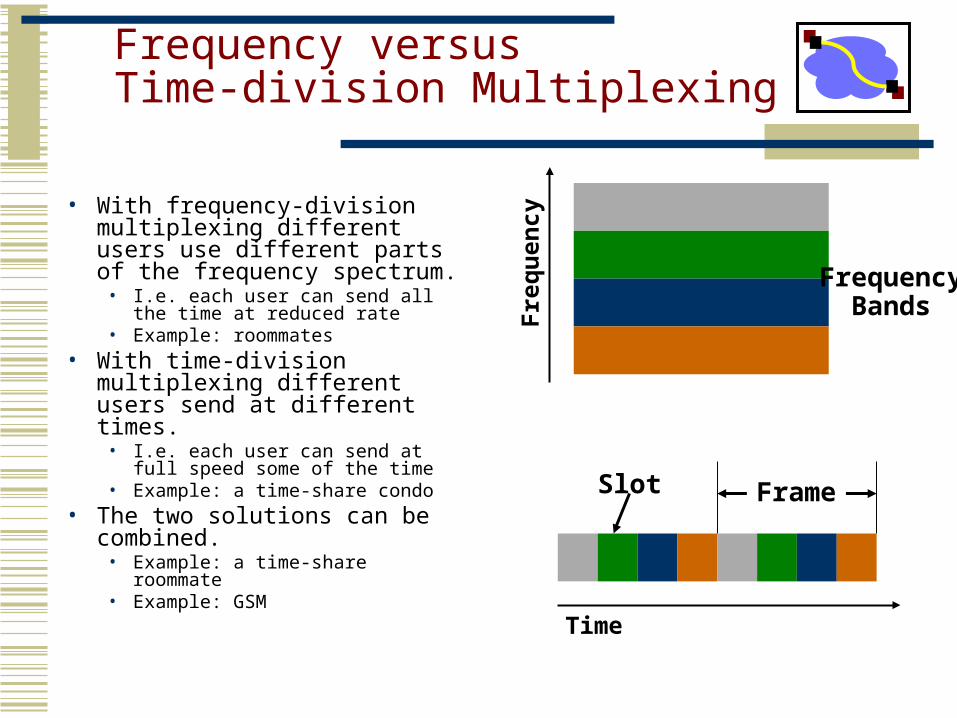
Frequency versus Time-division Multiplexing
• With frequency-division multiplexing different users use different parts of the frequency spectrum.
• I.e. each user can send all the time at reduced rate
• Example: roommates • With time-division multiplexing
different users send at different times.
• I.e. each user can send at full speed some of the time
• Example: a time-share condo• The two solutions can be
combined.• Example: a time-share roommate• Example: GSM
Fre
quen
cy
Time
FrequencyBands
Slot Frame
Outline
• Switching and Multiplexing• Link-Layer
• Ethernet and CSMA/CD• Bridges/Switches
• Routing-Layer• Physical-Layer
11
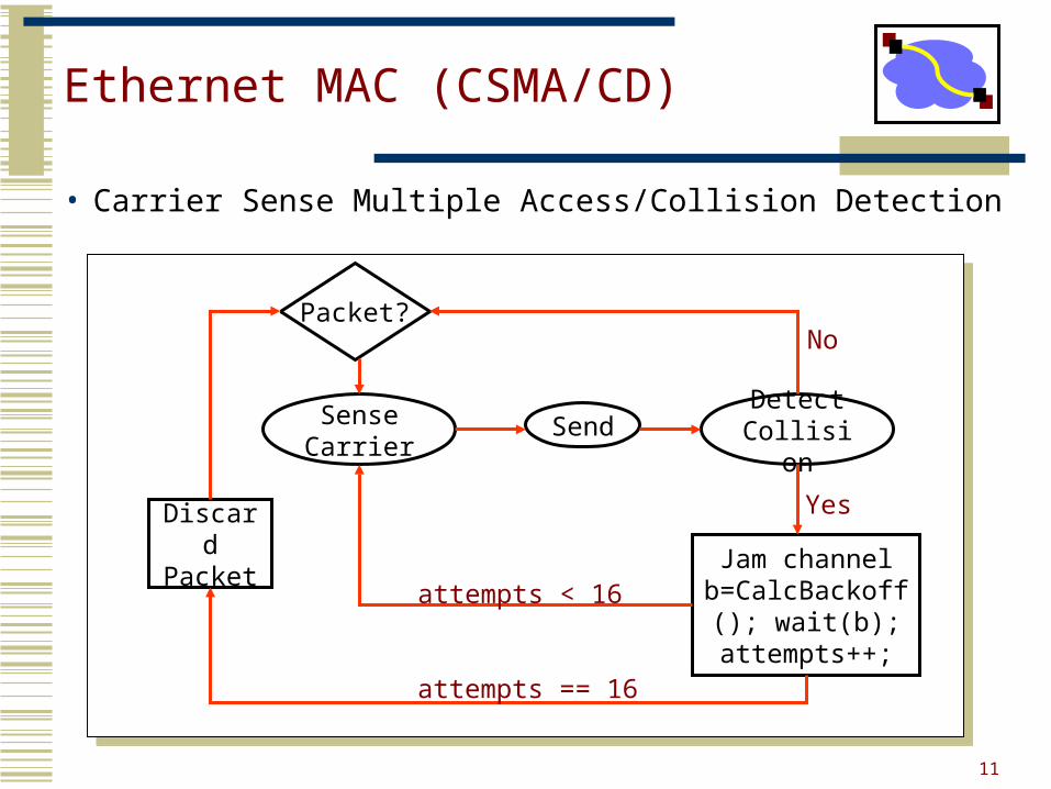
Ethernet MAC (CSMA/CD)
Packet?
Sense Carrier
Discard Packet
Send Detect Collision
Jam channel b=CalcBackoff();
wait(b);attempts++;
No
Yes
attempts < 16
attempts == 16
• Carrier Sense Multiple Access/Collision Detection
12
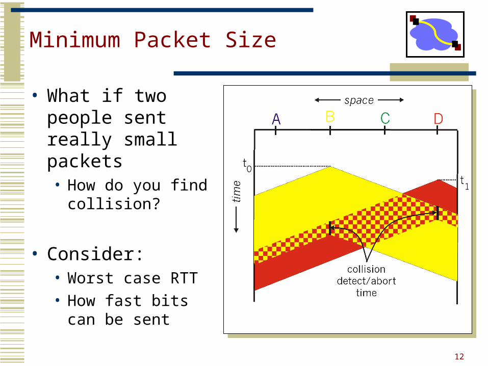
Minimum Packet Size
• What if two people sent really small packets• How do you find
collision?
• Consider:• Worst case RTT• How fast bits can
be sent
13
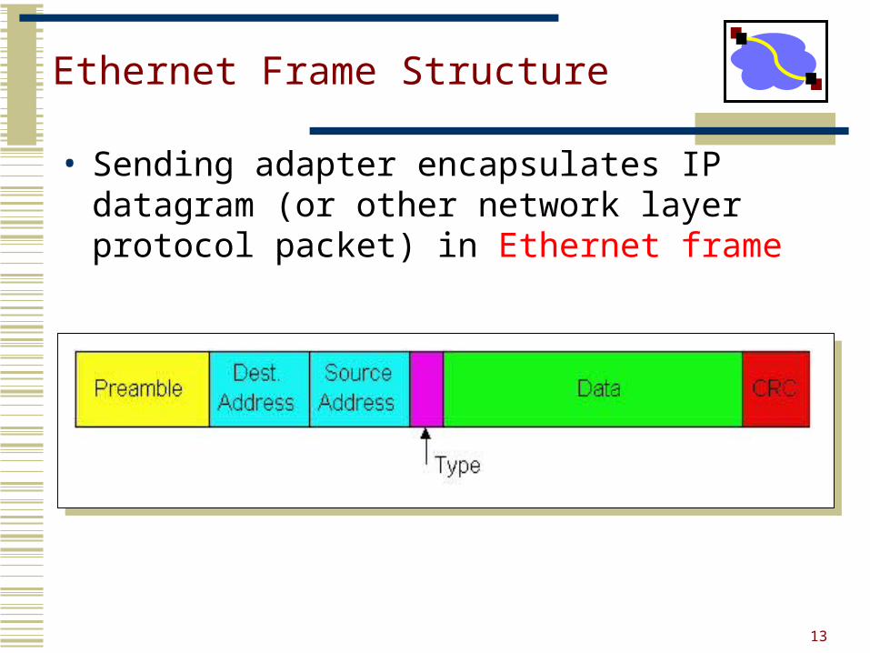
Ethernet Frame Structure
• Sending adapter encapsulates IP datagram (or other network layer protocol packet) in Ethernet frame
14
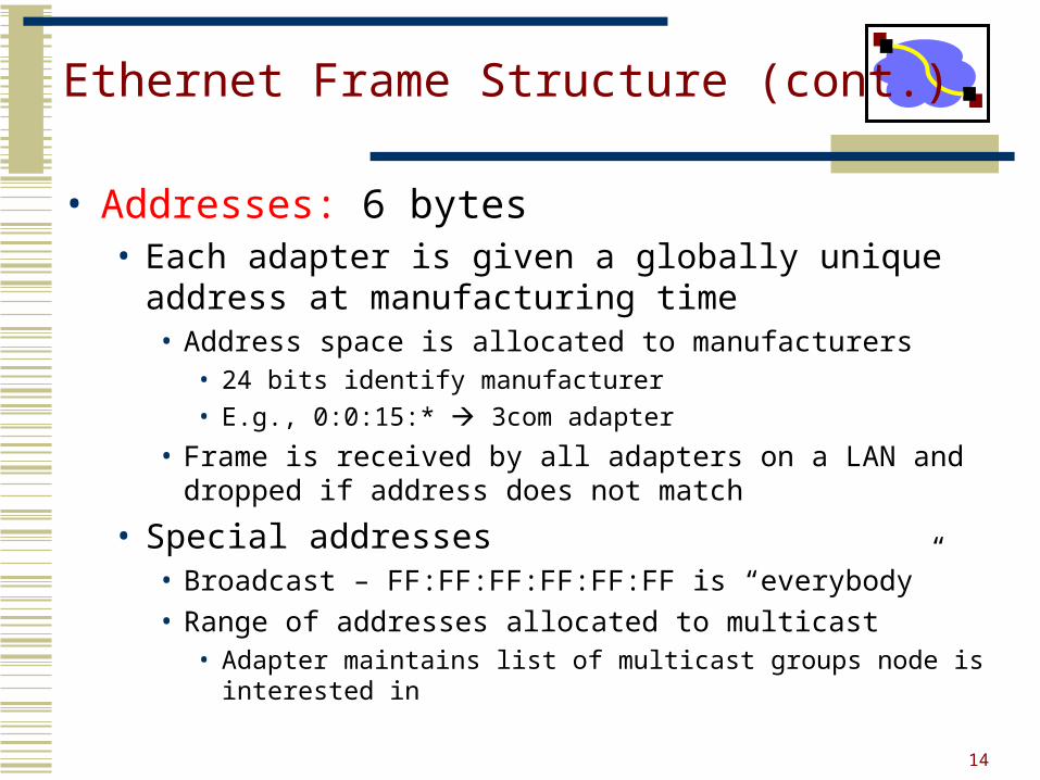
Ethernet Frame Structure (cont.)
• Addresses: 6 bytes• Each adapter is given a globally unique address at
manufacturing time• Address space is allocated to manufacturers
• 24 bits identify manufacturer
• E.g., 0:0:15:* 3com adapter
• Frame is received by all adapters on a LAN and dropped if address does not match
• Special addresses• Broadcast – FF:FF:FF:FF:FF:FF is “everybody”• Range of addresses allocated to multicast
• Adapter maintains list of multicast groups node is interested in
15
Summary
• CSMA/CD carrier sense multiple access with collision detection• Why do we need exponential backoff?• Why does collision happen?• Why do we need a minimum packet size?
• How does this scale with speed? (Related to HW)
• Ethernet• What is the purpose of different header fields?• What do Ethernet addresses look like?
• What are some alternatives to Ethernet design?
16
Transparent Bridges / Switches
• Design goals:• Self-configuring without hardware or software changes• Bridge do not impact the operation of the individual
LANs
• Three parts to making bridges transparent:1) Forwarding frames2) Learning addresses/host locations3) Spanning tree algorithm
17
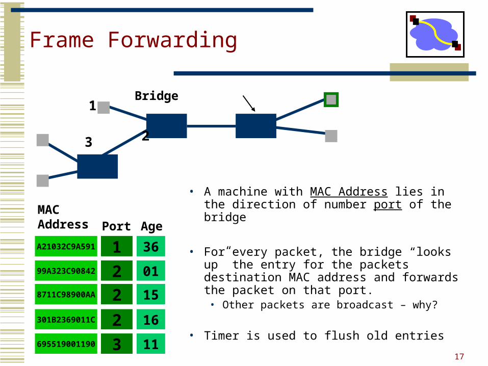
Frame Forwarding
• A machine with MAC Address lies in the direction of number port of the bridge
• For every packet, the bridge “looks up” the entry for the packets destination MAC address and forwards the packet on that port.• Other packets are broadcast – why?
• Timer is used to flush old entries
8711C98900AA 2
MAC Address Port
A21032C9A591 199A323C90842 2
301B2369011C 2695519001190 3
15
Age
36
01
16
11
Bridge1
3 2
18
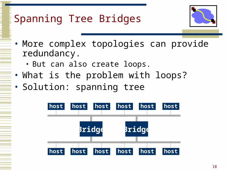
Spanning Tree Bridges
• More complex topologies can provide redundancy.• But can also create loops.
• What is the problem with loops?• Solution: spanning tree
host host host host host
host host host host host
host
host
Bridge Bridge
Outline
• Switching and Multiplexing• Link-Layer• Routing-Layer
• IP• IP Routing• MPLS
• Physical-Layer
20
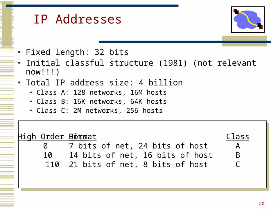
IP Addresses
• Fixed length: 32 bits• Initial classful structure (1981) (not relevant now!!!)• Total IP address size: 4 billion
• Class A: 128 networks, 16M hosts• Class B: 16K networks, 64K hosts• Class C: 2M networks, 256 hosts
High Order Bits0 10 110
Format7 bits of net, 24 bits of host14 bits of net, 16 bits of host21 bits of net, 8 bits of host
ClassABC
21
Subnet AddressingRFC917 (1984)
• Class A & B networks too big• Very few LANs have close to 64K hosts• For electrical/LAN limitations, performance or
administrative reasons
• Need simple way to get multiple “networks”• Use bridging, multiple IP networks or split up single
network address ranges (subnet)
22
Aside: Interaction with Link Layer
• How does one find the Ethernet address of a IP host?
• ARP (Address Resolution Protocol)• Broadcast search for IP address
• E.g., “who-has 128.2.184.45 tell 128.2.206.138” sent to Ethernet broadcast (all FF address)
• Destination responds (only to requester using unicast) with appropriate 48-bit Ethernet address• E.g, “reply 128.2.184.45 is-at 0:d0:bc:f2:18:58” sent to
0:c0:4f:d:ed:c6
23
Classless Inter-Domain Routing(CIDR) – RFC1338
• Allows arbitrary split between network & host part of address • Do not use classes to determine network ID• Use common part of address as network number• E.g., addresses 192.4.16 - 192.4.31 have the first 20
bits in common. Thus, we use these 20 bits as the network number 192.4.16/20
• Enables more efficient usage of address space (and router tables) How?• Use single entry for range in forwarding tables• Combined forwarding entries when possible
24
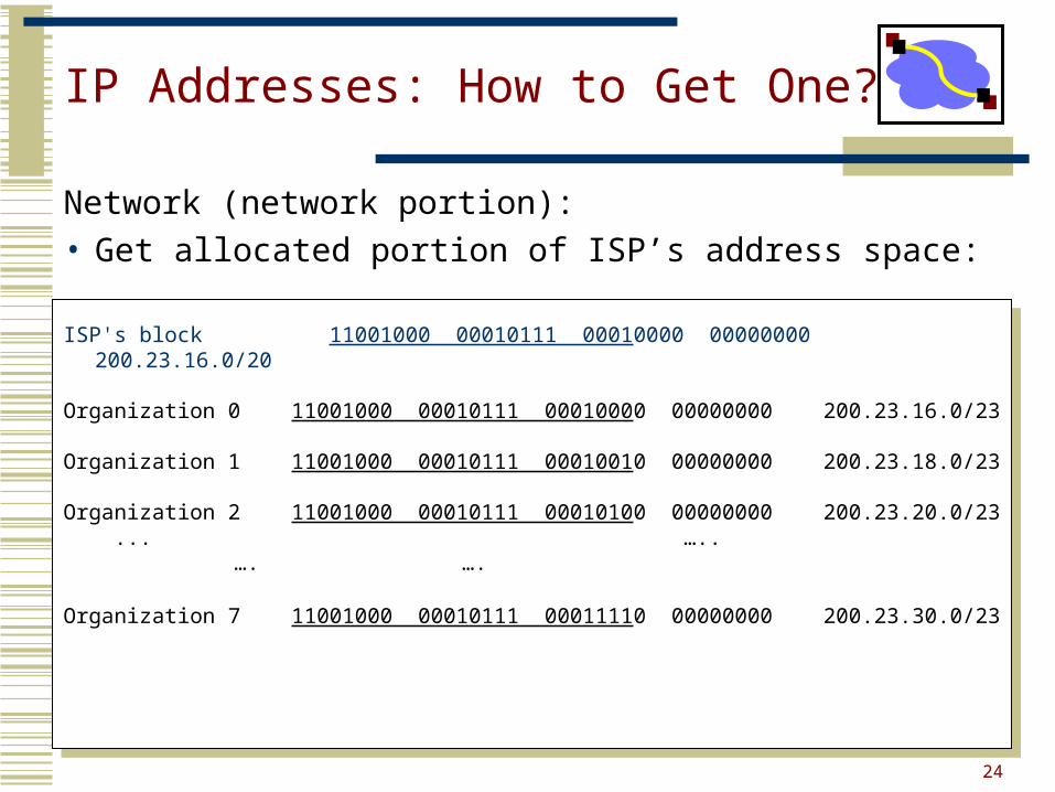
IP Addresses: How to Get One?
Network (network portion):• Get allocated portion of ISP’s address space:
ISP's block 11001000 00010111 00010000 00000000 200.23.16.0/20
Organization 0 11001000 00010111 00010000 00000000 200.23.16.0/23
Organization 1 11001000 00010111 00010010 00000000 200.23.18.0/23
Organization 2 11001000 00010111 00010100 00000000 200.23.20.0/23 ... ….. …. ….
Organization 7 11001000 00010111 00011110 00000000 200.23.30.0/23
25
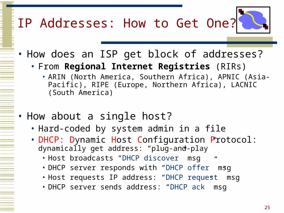
IP Addresses: How to Get One?
• How does an ISP get block of addresses?• From Regional Internet Registries (RIRs)
• ARIN (North America, Southern Africa), APNIC (Asia-Pacific), RIPE (Europe, Northern Africa), LACNIC (South America)
• How about a single host?• Hard-coded by system admin in a file• DHCP: Dynamic Host Configuration Protocol: dynamically
get address: “plug-and-play”• Host broadcasts “DHCP discover” msg• DHCP server responds with “DHCP offer” msg• Host requests IP address: “DHCP request” msg• DHCP server sends address: “DHCP ack” msg
26
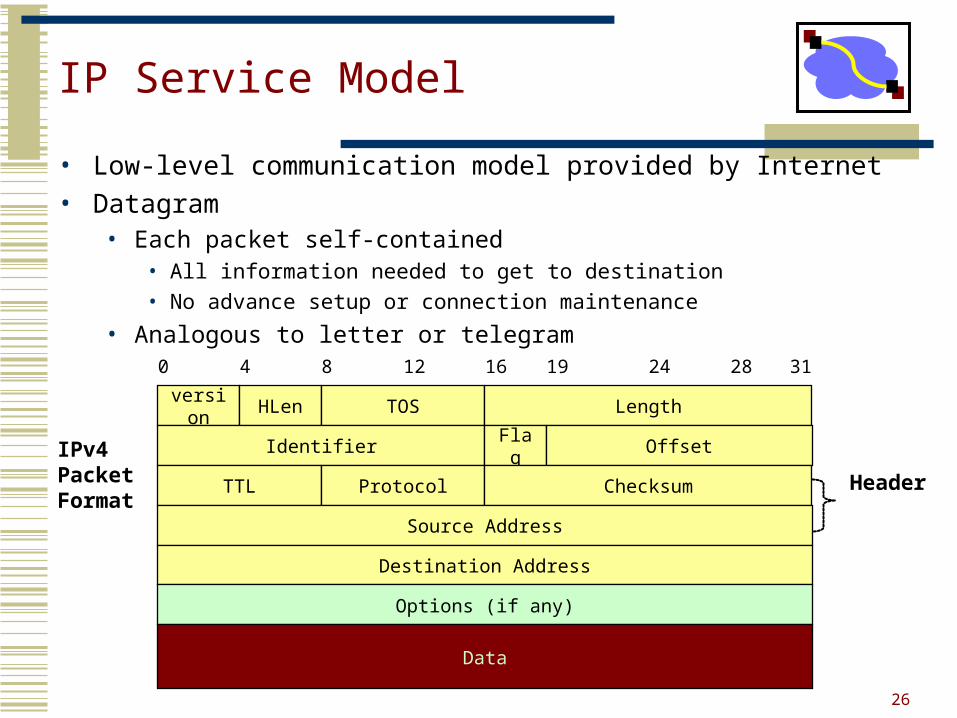
IP Service Model
• Low-level communication model provided by Internet• Datagram
• Each packet self-contained• All information needed to get to destination• No advance setup or connection maintenance
• Analogous to letter or telegram0 4 8 12 16 19 24 28 31
version HLen TOS Length
Identifier Flag Offset
TTL Protocol Checksum
Source Address
Destination Address
Options (if any)
Data
Header
IPv4 PacketFormat
27
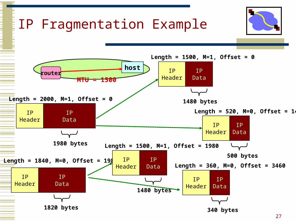
IP Fragmentation Example
IPHeader
IPData
Length = 2000, M=1, Offset = 0
1980 bytes
IPData
IPHeader
Length = 1840, M=0, Offset = 1980
1820 bytes
hostrouter
MTU = 1500
IPHeader
IPData
Length = 1500, M=1, Offset = 0
1480 bytes
IPHeader
IPData
Length = 520, M=0, Offset = 1480
500 bytesIP
HeaderIP
Data
Length = 1500, M=1, Offset = 1980
1480 bytes
IPHeader
IPData
Length = 360, M=0, Offset = 3460
340 bytes
28
Important Concepts
• Base-level protocol (IP) provides minimal service level• Allows highly decentralized implementation• Each step involves determining next hop• Most of the work at the endpoints
• ICMP provides low-level error reporting
• IP forwarding global addressing, alternatives, lookup tables
• IP addressing hierarchical, CIDR• IP service best effort, simplicity of routers• IP packets header fields, fragmentation, ICMP
29
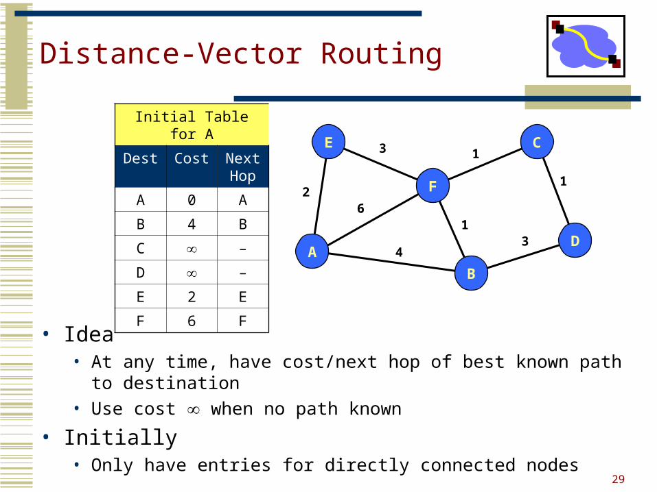
Distance-Vector Routing
• Idea• At any time, have cost/next hop of best known path to destination• Use cost when no path known
• Initially• Only have entries for directly connected nodes
A
E
F
C
D
B
2
3
6
4
1
1
1
3
Initial Table for A
Dest Cost Next Hop
A 0 A
B 4 B
C –
D –
E 2 E
F 6 F
30
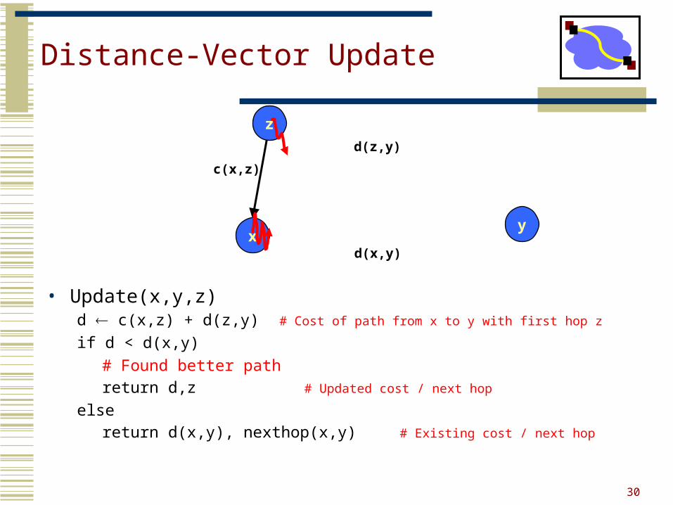
Distance-Vector Update
• Update(x,y,z)d c(x,z) + d(z,y) # Cost of path from x to y with first hop z
if d < d(x,y)
# Found better path
return d,z # Updated cost / next hop
else
return d(x,y), nexthop(x,y) # Existing cost / next hop
x
z
y
c(x,z)
d(z,y)
d(x,y)
31
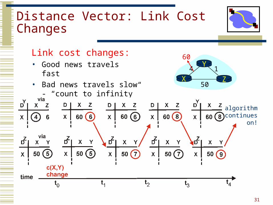
Distance Vector: Link Cost Changes
Link cost changes:• Good news travels fast • Bad news travels slow -
“count to infinity” problem!X Z
14
50
Y60
algorithmcontinues
on!
32
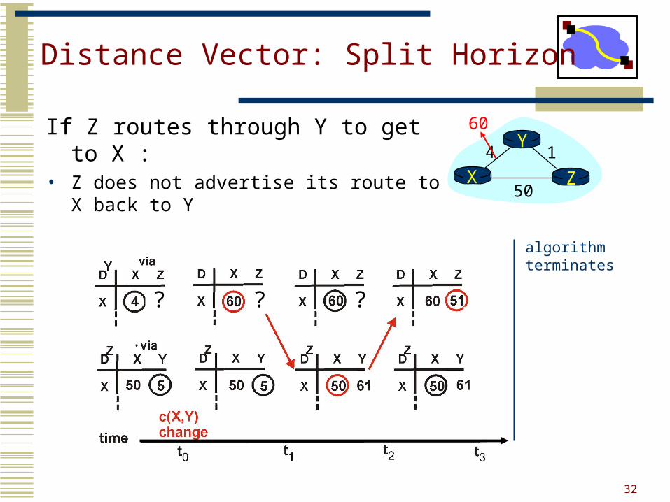
Distance Vector: Split Horizon
If Z routes through Y to get to X :• Z does not advertise its route to X back to Y
algorithmterminates
X Z14
50
Y60
? ? ?
33
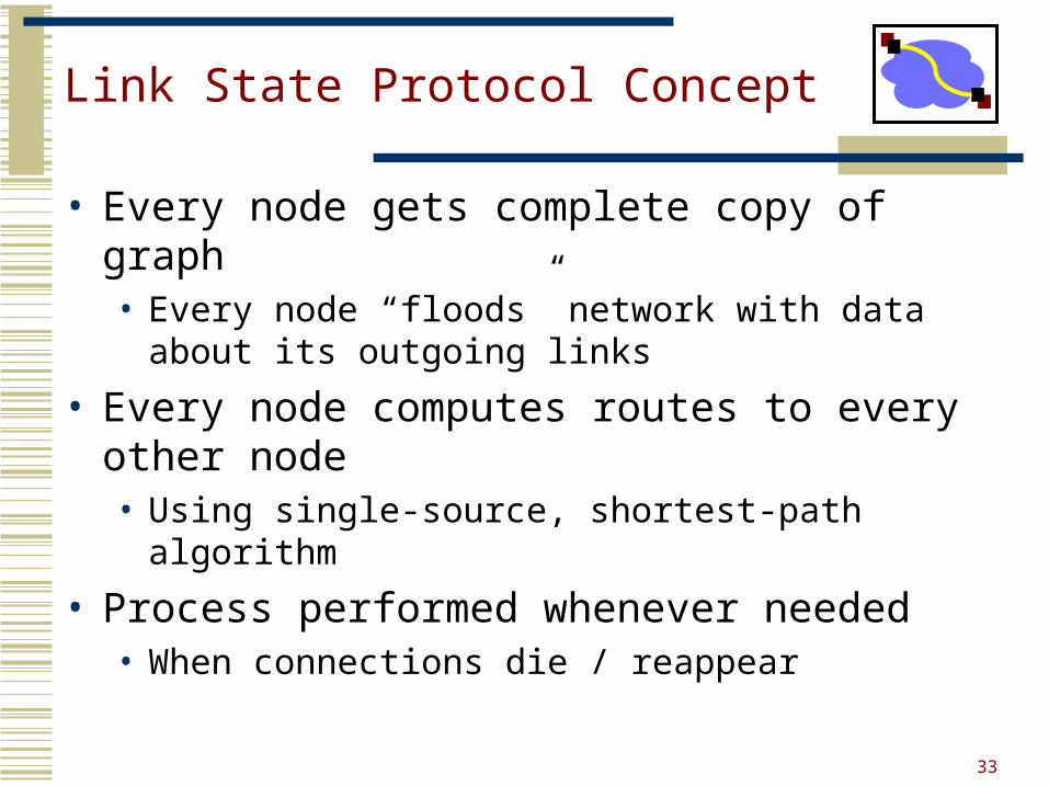
Link State Protocol Concept
• Every node gets complete copy of graph• Every node “floods” network with data about its
outgoing links
• Every node computes routes to every other node• Using single-source, shortest-path algorithm
• Process performed whenever needed• When connections die / reappear
34
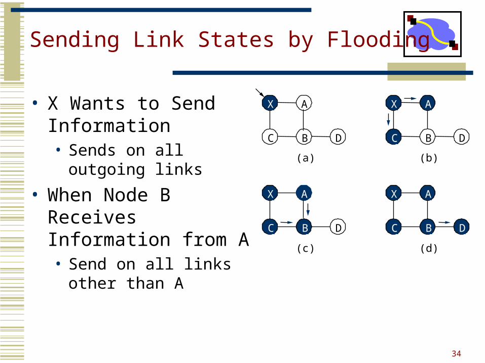
Sending Link States by Flooding
• X Wants to Send Information• Sends on all outgoing
links
• When Node B Receives Information from A• Send on all links other
than A
X A
C B D
(a)
X A
C B D
(b)
X A
C B D
(c)
X A
C B D
(d)
35
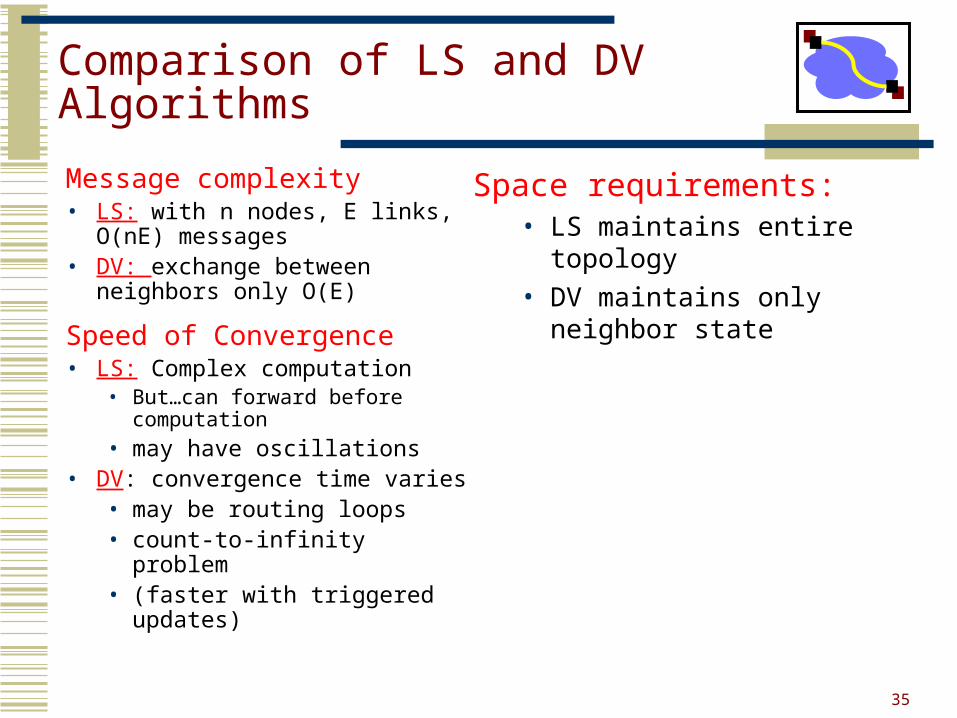
Comparison of LS and DV Algorithms
Message complexity• LS: with n nodes, E links, O(nE)
messages• DV: exchange between
neighbors only O(E)
Speed of Convergence• LS: Complex computation
• But…can forward before computation
• may have oscillations• DV: convergence time varies
• may be routing loops• count-to-infinity problem• (faster with triggered
updates)
Space requirements:• LS maintains entire topology• DV maintains only neighbor
state
36
Internet
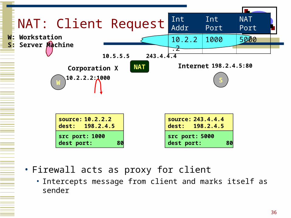
NAT: Client Request
• Firewall acts as proxy for client• Intercepts message from client and marks itself as sender
Corporation X
W
NAT
W: WorkstationS: Server Machine
10.2.2.2:1000 S
198.2.4.5:80
243.4.4.410.5.5.5
source: 10.2.2.2dest: 198.2.4.5
src port: 1000dest port: 80
source: 243.4.4.4dest: 198.2.4.5
src port: 5000dest port: 80
Int Addr Int Port NAT Port
10.2.2.2 1000 5000
37
Internet
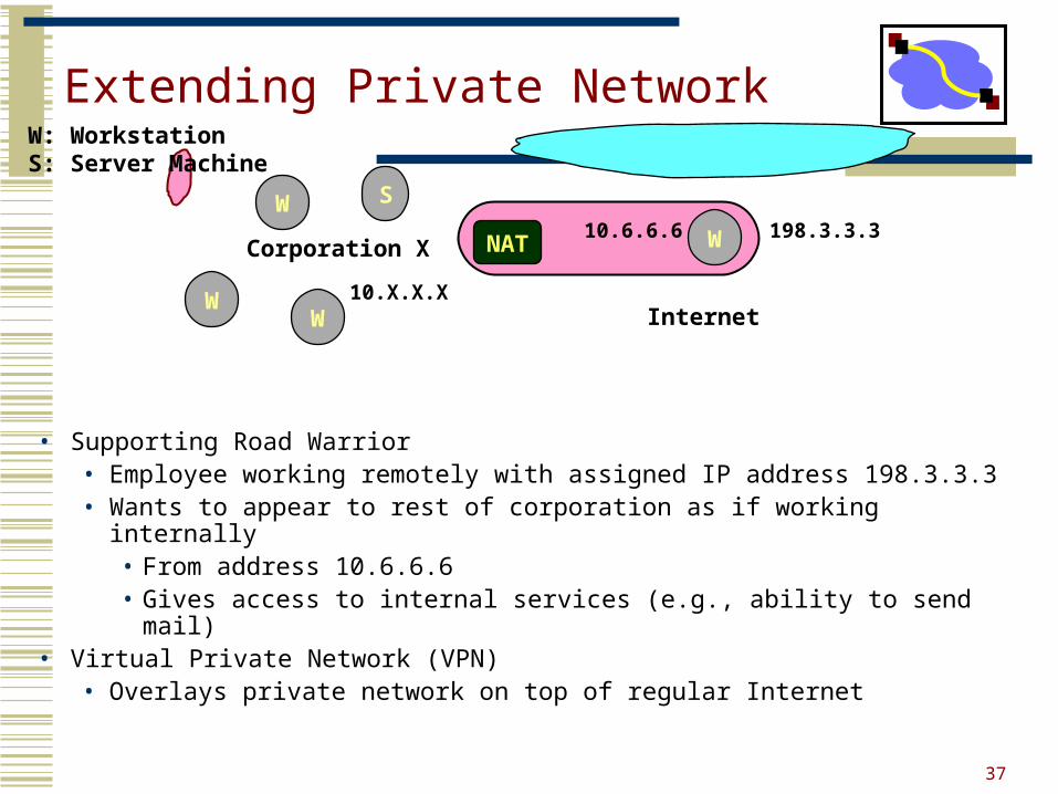
Extending Private Network
• Supporting Road Warrior• Employee working remotely with assigned IP address 198.3.3.3• Wants to appear to rest of corporation as if working internally
• From address 10.6.6.6• Gives access to internal services (e.g., ability to send mail)
• Virtual Private Network (VPN)• Overlays private network on top of regular Internet
Corporation X
W
W
W
S
W: WorkstationS: Server Machine
198.3.3.310.6.6.6
10.X.X.X
WNAT
38
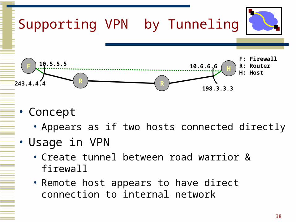
Supporting VPN by Tunneling
• Concept• Appears as if two hosts connected directly
• Usage in VPN• Create tunnel between road warrior & firewall• Remote host appears to have direct connection to
internal network
HF
R R198.3.3.3
243.4.4.4
10.5.5.5 10.6.6.6F: FirewallR: RouterH: Host
39
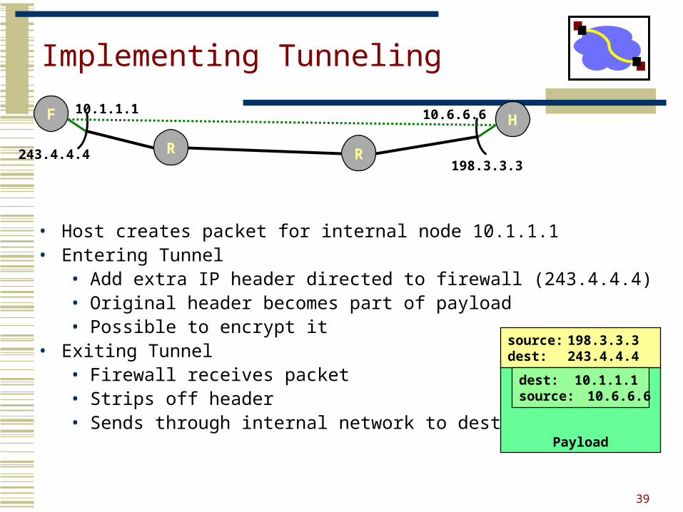
Implementing Tunneling
• Host creates packet for internal node 10.1.1.1 • Entering Tunnel
• Add extra IP header directed to firewall (243.4.4.4)• Original header becomes part of payload• Possible to encrypt it
• Exiting Tunnel• Firewall receives packet• Strips off header• Sends through internal network to destination
HF
R R198.3.3.3
243.4.4.4
10.1.1.1 10.6.6.6
Payload
source: 198.3.3.3dest: 243.4.4.4
dest: 10.1.1.1source: 10.6.6.6
40
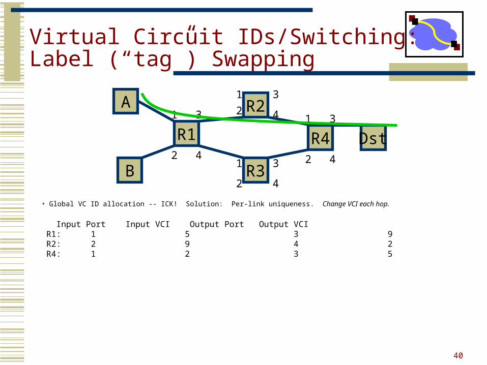
Virtual Circuit IDs/Switching:Label (“tag”) Swapping
• Global VC ID allocation -- ICK! Solution: Per-link uniqueness. Change VCI each hop.
Input Port Input VCI Output Port Output VCI R1: 1 5 3 9 R2: 2 9 4 2 R4: 1 2 3 5
A
B
R2
R1
R3
R4 Dst
1
2
3
4
3
3
3
1
1
1
2
2
4
4
4
2
41
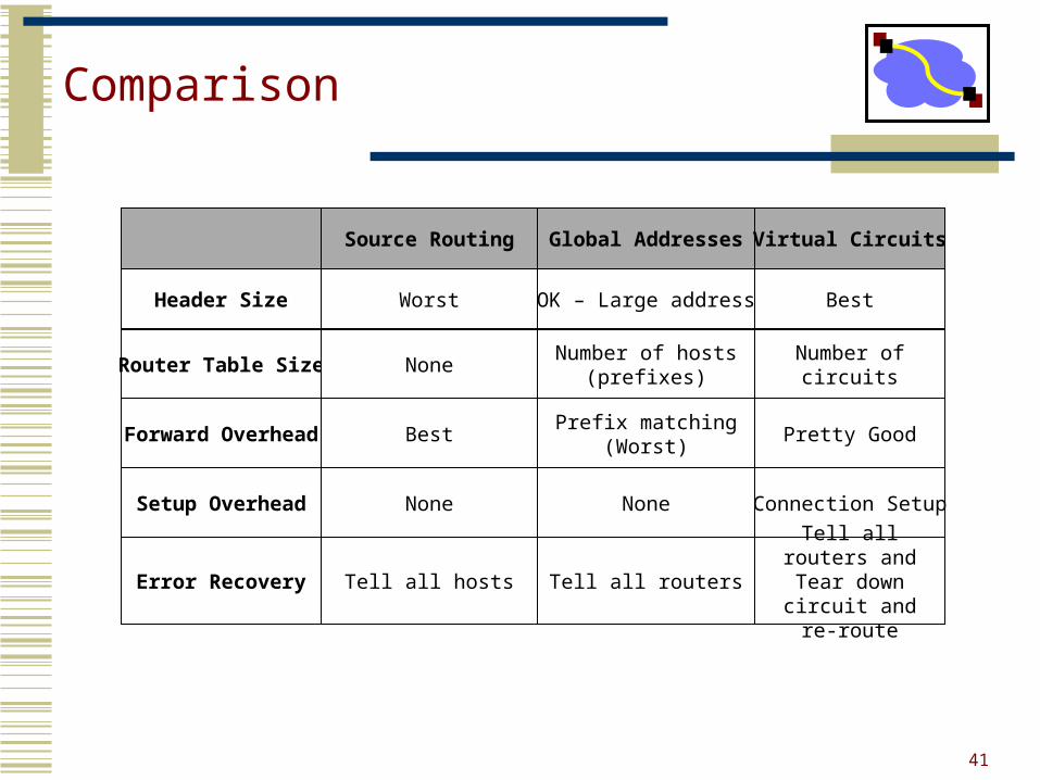
Comparison
Source Routing Global Addresses
Header Size Worst OK – Large address
Router Table Size NoneNumber of hosts
(prefixes)
Forward Overhead BestPrefix matching
(Worst)
Virtual Circuits
Best
Number of circuits
Pretty Good
Setup Overhead None None
Error Recovery Tell all hosts Tell all routers
Connection Setup
Tell all routers and Tear down circuit
and re-route
42
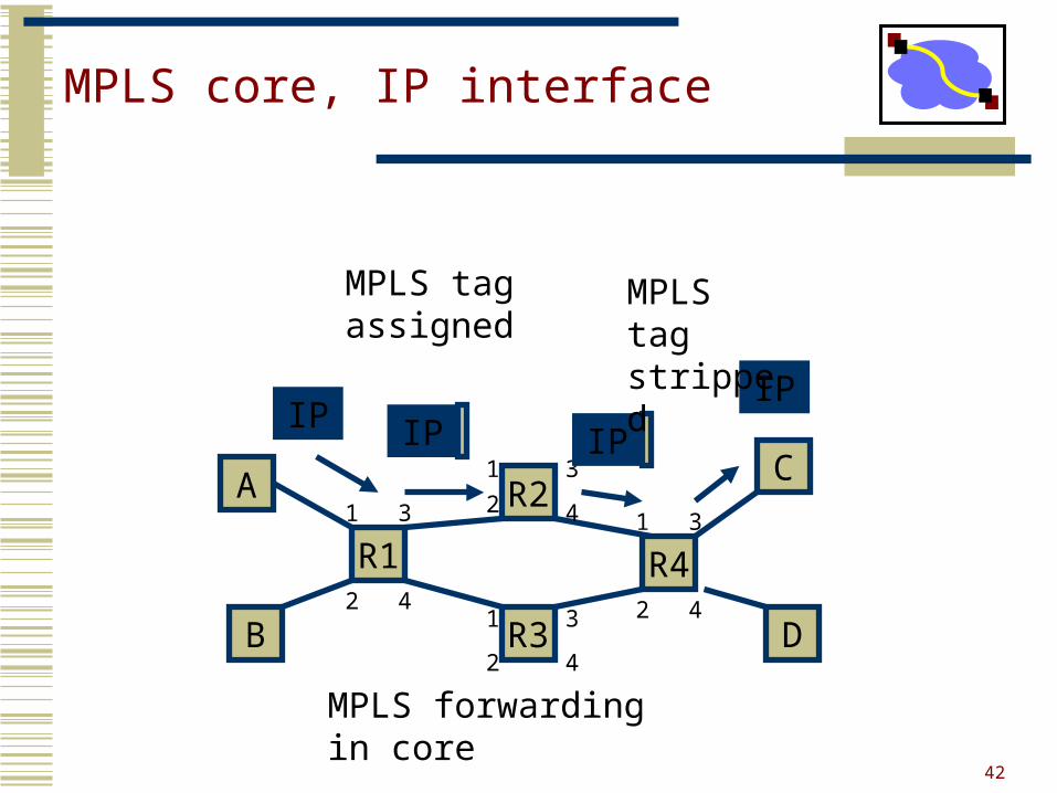
MPLS core, IP interface
A
B
R2
R1
R3
R4
C1
2
3
4
3
3
3
1
1
1
2
2
4
4
4
2
D
IP IP
MPLS tag assigned
IP
IP
MPLS forwarding in core
MPLS tag stripped
Outline
• Switching and Multiplexing• Link-Layer• Routing-Layer• Physical-Layer
• Encodings
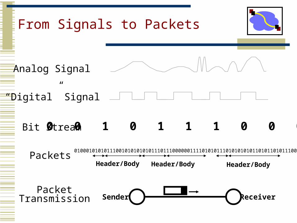
From Signals to Packets
Analog Signal
“Digital” Signal
Bit Stream 0 0 1 0 1 1 1 0 0 0 1
Packets0100010101011100101010101011101110000001111010101110101010101101011010111001
Header/Body Header/Body Header/Body
ReceiverSenderPacket
Transmission
Encoding
• We use two discrete signals, high and low, to encode 0 and 1
• The transmission is synchronous, i.e., there is a clock used to sample the signal• In general, the duration of one bit is equal to one or two
clock ticks
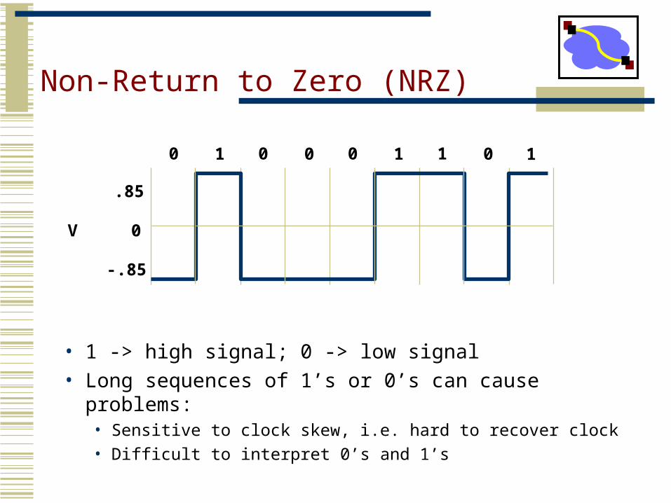
Non-Return to Zero (NRZ)
• 1 -> high signal; 0 -> low signal• Long sequences of 1’s or 0’s can cause problems:
• Sensitive to clock skew, i.e. hard to recover clock• Difficult to interpret 0’s and 1’s
V 0
.85
-.85
0 0 0 11 0 1 0 1
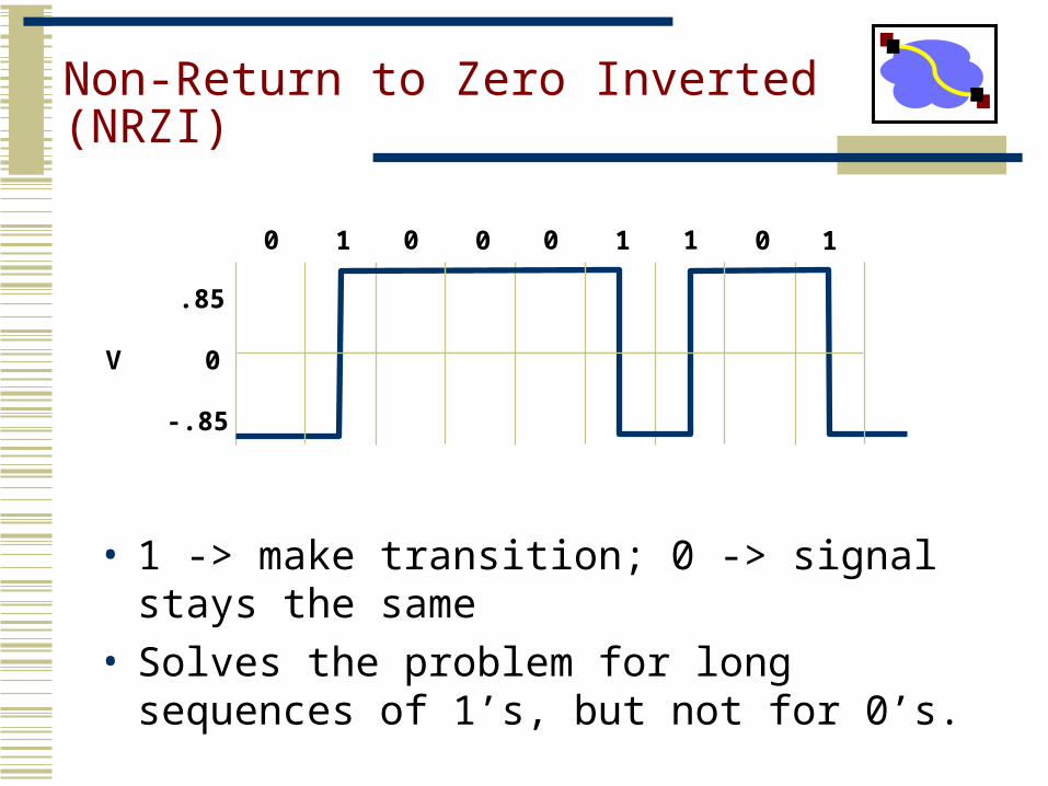
Non-Return to Zero Inverted (NRZI)
• 1 -> make transition; 0 -> signal stays the same
• Solves the problem for long sequences of 1’s, but not for 0’s.
V 0
.85
-.85
0 0 0 11 0 1 0 1
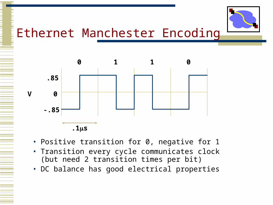
Ethernet Manchester Encoding
• Positive transition for 0, negative for 1• Transition every cycle communicates clock (but
need 2 transition times per bit)• DC balance has good electrical properties
V 0
.85
-.85
0 1 1 0
.1s
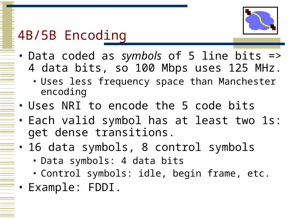
4B/5B Encoding
• Data coded as symbols of 5 line bits => 4 data bits, so 100 Mbps uses 125 MHz.• Uses less frequency space than Manchester encoding
• Uses NRI to encode the 5 code bits• Each valid symbol has at least two 1s: get dense
transitions.• 16 data symbols, 8 control symbols
• Data symbols: 4 data bits• Control symbols: idle, begin frame, etc.
• Example: FDDI.
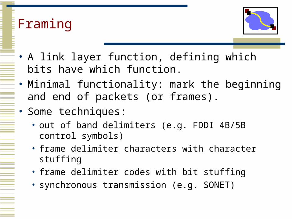
Framing
• A link layer function, defining which bits have which function.
• Minimal functionality: mark the beginning and end of packets (or frames).
• Some techniques:• out of band delimiters (e.g. FDDI 4B/5B control
symbols)• frame delimiter characters with character stuffing• frame delimiter codes with bit stuffing• synchronous transmission (e.g. SONET)
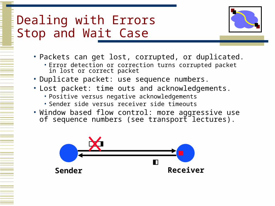
Dealing with ErrorsStop and Wait Case
• Packets can get lost, corrupted, or duplicated. • Error detection or correction turns corrupted packet in lost or
correct packet• Duplicate packet: use sequence numbers.• Lost packet: time outs and acknowledgements.
• Positive versus negative acknowledgements• Sender side versus receiver side timeouts
• Window based flow control: more aggressive use of sequence numbers (see transport lectures).
Sender Receiver