Embed Size (px)
Citation preview

Advanced Course Ch.8 Receiversde VE1FA
“If you can’t hear the station, you can’t work it…”
Marconi 16 crystal receiver 1914Kenwood TS-890 transceiver 2019

What a receiver must do:
1. Signal capture
2. Selection
3. Amplification
4. Detection (signal processing to recover information)
5. Amplification
6. Present information in human-understandable form
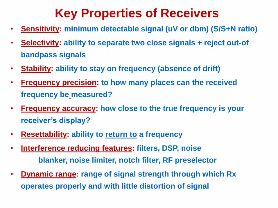
Key Properties of Receivers• Sensitivity: minimum detectable signal (uV or dbm) (S/S+N ratio)
• Selectivity: ability to separate two close signals + reject out-of
bandpass signals
• Stability: ability to stay on frequency (absence of drift)
• Frequency precision: to how many places can the received
frequency be measured?
• Frequency accuracy: how close to the true frequency is your
receiver’s display?
• Resettability: ability to return to a frequency
• Interference reducing features: filters, DSP, noise
blanker, noise limiter, notch filter, RF preselector
• Dynamic range: range of signal strength through which Rx
operates properly and with little distortion of signal

1900-1920s Crystal Radio
Despite what your T-book says, this is NOT what is called a TRF radio!
Powered by the transmitter! (no ampifiers)!

Regenerative receivers (1920s)
--simple circuits using active device(s)
--high sensitivity
--high selectivity (for weaker signals)
--cheap + easy to build!
--poor stability
--poor immunity to overload
--mediocre resettability + logging
--best performance requires careful design

Basic 1-tube regenerative receiver
Regeneration allows:-very high gain (close to oscillation point)-very high coil Q good selectivity-poor stability-transmitting with your receiver...not good!

National SW-3 Regenerative Amateur Receiver (100 kHz to 30 MHz (with all 10 coil sets!)
100-150 VDC 2.5 or 6.3 V
RF Amp.Regenerative detector
Audio amp.
phones
GainRegen.
+ -

National SW-3 Regenerative receiver
-cheap, high sensitivity, thousands sold in 1930s (Depression)-widely copied in home-brew ham receivers in 1930s

1932 Home-brew 3-tube regenerative receiver
by ZL1BN (capable of trans-Pacific CW DX!)

Tuned Radio Frequency (TRF) Receiver (1920s)
-commonest type of AM broadcast receiver in the 1920s
-poor selectivity and sensitivity on HF frequencies
-pre-1930s low-gain triodes almost useless above 2 MHz (2 Mc)

1920s: the Tuned Radio Frequency (TRF)
Receiver or “three-dialer”
-RFamp=>RFamp=>Det =>
AFamp=>AFamp => output
-better AM, easier to use
than regenerative
- amplifier gain very low
at higher frequencies
-on HF, bandpass much
too wide
-stability problems on HF

Synchrodyne = Direct conversion = Homodyne = Zero IF receiver
-mixes and downconverts to audio, but no IF stages-widely used in lightweight portable low-power “QRP” radios-can be very simple, sensitive, stable
Mixer AudioRF
Signal =7030 OR 7029 LO= 7029.5
MIXER audio filter audio amp. 500 Hz
Signal=7030 LO=7029.5 OR 7030.5
MIXER audio filter audio amp. 500 Hz
SIGNAL
OUTPUT
Every signal received at 2 points on the dial!

“QRP-type” synchrodyne/direct conversion RX
-local oscillator tuned to carrier frequency of incoming signal-dual-gate MOSFET mixer-mixer produces oscillator output +/- the audio frequency of the signal-pi filter rejects RF, passes AF-LM-741 circuit selectively amplifies desired audio frequency range
Problems: (1) images! (2) unprotected signal gate; (3)no GND ref.! (4) low audio out!

NE602 : double-balanced mixer, oscillator and voltage regulator
Cheap, fully balanced, works up into VHF range

NE-602
LM-386
LM-7809
40m Direct Conversion Receiver
Ant.
phones
+12 VDC

Direct conversion single band QRP CW transceiver

The Superheterodyne Receiver
Superheterodyne RX invented by E.H. Armstrong in US Army lab in Paris in 1917.Came into use in consumer AM 540-1500 kHz reception about 1930.
Came into use in HF communications after 5 “What’s Wrong With Our Receivers” articles in QST by C. Lamb in 1931-32.
Mixing (“heterodyning”) two frequencies together to get a usefuldifference frequency suggested by R. Fessenden in 1905
E.H. Armstrong prototype receiver (1917) IF = 75 kHz

RCA AR-88 (1940) -probably the best HF receiver in WW2-single conversion, Xtal filter, high selectivity, noise limiter-100+ lbs!, 100/240 V, 50-60 Hz, 0.54-32 MHz range-lend-lease to Russia-huge advance over any non-superheterodyne receiver

AntennaTuned* Radio
Frequency
Amplifier
Speaker
Or
Headphone
Audio
Frequency
Amplifier
Detector
LC Tuned*VFO/LO
Intermediate
Frequency
Amplifier
Tuned* Mixer IF Filter
3800 kHz signal
+ many others 3800 kHz
4255 kHz
4255 + 3800 = 8055 kHz
and
4255 – 3800 = 455 kHz
455 kHz
455 kHz
Single conversion 80m AM superhet
* “ganged” or synchronous
tuning (3 LCs)
LC LC455 kHz
LC
LC¤
¤
¤ fixed-tuned on455 kHz

Advantages of a constant, low intermediate frequency (IF)
• 1. Optimized amplifier design.
• 2. Narrow bandpass (good selectivity with fixed LC, crystal
and mechanical filters).
• 3. Stable, high gain amplifiers easy.
455 kHz=>455kHz=>

Superhet Characteristics
-Stability of RX depends on the local oscillator(s).
-Gain mostly produced in the IF amplifiers (optimized for 1 frequency)
-Selectivity: fixed IF allows selective crystal, mechanical, and DSP filters.
-Internal noise depends on “front end” (RF and first mixer stages).
-Image problems: minimized by good IF design + multiple IF frequencies (dual or triple conversion).
-Tracking problems: removed by broadband front end tuning + digitaldisplay.
-Newer superhets: (1) diode switching of circuits;(2) optical encoding tuning; and (3) broadband front end filters.

Superheterodyne + SDR (software defined radio) are THE types of RX commonly used today.
Modern superhets have a lot of digital circuits controlled via software and firmware.
Modern SDRs depend on superhet-like local oscillators and frequency mixing.
Main advantage of superhet over older RX designs: amplificationand bandpass shaping (selectivity) done a low constant frequencywhere they can be optimized.

Local oscillator (LO)-may be any design, e.g. Hartley, Colpitts, Clapp, Armstrong, etc -LO stability determines stability of whole radio-clean output reduces spurious outputs of mixer-LO usually stronger than signal entering mixer (by design)-may be set either above or below signal frequency
kHz – 2000 kHz = 455 kHz2455 kHz -- 2000 kHz = 455 kHz (Image) 1545 is 63% of 2455
28.000 kHz – 27.545 kHz = 455 kHz (Image) 27.090 is 97% of 28.000 27.090 kHz – 27.545 kHz = 455 kHz
Distant image: well rejectedClose image: poorly rejected
Q and number of tuned circuits in front of mixer also key to makingimage much weaker than selected frequency
Image frequenciesSignal LO IF
1545

By increasing the IF frequency: difference between correct signal and image increases
Increased signal:image difference better image rejection
BUT lower IF = better LC, crystal, + mechanical filter selectivity!
Solution: use both high + low IFs!(dual conversion)
Requires 2 mixersExample: (9.0 MHz and 455 kHz )
Triple conversion: typically70 MHz 8 -12 MHz 455 kHz
Reduces images even more

Birdies- unintended internally-generated signals in a superhet. RX
-all superhets have them
-usually oscillator harmonics, or mixer, PLL, or DDS by-products
-remove the antenna...and the birdies remain unchanged
-reflection of circuit design quality
-the more different IFs, the more different LOs to produce birdies
-designers often add “suck-out” resonant traps to removebirdies

Other superhet problems
Spurious responses: out-of-band signals that end up in theIF bandpass due to mixing with stray internally generatedfrequencies.
Cross-modulation/Intermodulation: two strong input signals mix in the front end of the radio, resulting in poor or unintelligible signal.
-more common at VHF, where front ends allow a broad band of signals into the mixer.
-putting a big VHF or UHF antenna on a handie-talkie in a city often renders the radio useless, due to the number of nearby strong
signals.
-one reason for “cavities” or ”duplexers” in VHF and UHF repeater systems. These are very high Q resonators.

VHF helical filter-sharpens (narrows) front-endbandpass
-can have many sections for high selectivity
-coil tap sets Z
VHF+UHF repeater “cavities”-very high Q resonators
-used on both TX output and RX input
-greatly reduces “intermod”
-prevents TX output from “drowning” RX input, which is just 600 kHz away

Classic Lamb single-crystal IF filter: widely used 1934-1960s
X1
X1 ---at IF frequency (between 400 and 1000 kHz)
Great improvement in CW selectivity-also notches out QRM-improves S/N ratio-takes practice to use properly
Proper filter tuning: requires: RF gain, tuning, crystal phasing (C1), and crystal coupling (C2)
MIXER
SIGNAL

Peak and notch: single-crystal filter in bridge-peak and notch adjustable with phasing and coupling controls-peak + notch can be made very sharp-receiver drift is a problem

Modern variable selectivity: series of fixed bandpass filters selected/de-selected using “signal steering diodes”
-all on the same IF center frequency
-numbers indicate bandwidthat -6dB points
-ceramic filters, much cheaperthan crystal, with slightly reduced performance
-filters are passive (attenuatethe signal about 2-8 dB)
-in dual/triple conversion, filters used at at least 2 IFs, e.g. 9.0 and 0.455 MHz

MCF = monolithic crystal filter
Discrete crystal filter
-build yourself with cheap computer crystals
Mechanical filter

3 different Kenwood xtal filtersat 8.83 and 10.7 MHz
Rockwell-Collins mechanicalfilter at 455 kHz for AM
3 different shape factors
Filter performance can be ruined by “blowby”

Ideal Receiver
Selectivity
(perfect skirts)
60 dB
Filter skirt
Real receiverselectivity
Shape factor: 6 dB to 60dB bandwidth ratio

Adjustable analog notch filter to take out tones

Dual-conversion superhet
9.0 Mhz 0.455 MHz
BW=2.4 BW=2.4kHz
Q. What if you could slightly vary the frequencies of the 2 LOs??

Variable IF selectivity: 2 IF frequencies, with both LOs adjustable
SSB “slope tune” (high cut-low cut)
“Passband tuning”
IF Passband

IF offset (another example)
Both DSP and analog notches can be wide or narrow
“Autonotch” vs. manual notch
Multi vs. single autonotch
Audio vs. IF autonotch

Internal receiver noise (independent of antenna)-usually dependent on “front end design” -mainly noise created in RF amp or first mixer/oscillator-limits weak signal detection (sensitivity) and copy-low current devices are the quietest (diode or FET mixers)
Sensitivity: minimum signal giving a 10dB S/N ratio-in a modern HF receiver this is about 0.13μV@50Ω, or -140 dBm@ 50Ω (for SSB, CW, FSK). For very narrow modes detectable sigs arelower. WSJT modes: sigs copyable down to 26dB below noise.-alternatively in HF, the MDS, or “Minimum Discernable Signal” (a CW signal you can just barely copy) can be used-MDS is about -140 dBm-spectrum gets quieter as frequency goes up-RF amplifier only used if really necessary -under low band-high noise, also insert Attenuator-continuous noise readable on the S-meter reduces dynamic range

AGC/AVC (automatic gain or volume control)
-negative feedback to give both strong and weak signals aboutthe same audio volume out.
-fast attack/slow release (usually adjustable)
-useful for most modes
-control DC voltage usually rectified from IF signal voltage, or occasionally from audio signal voltage
-weak signals no AGC voltage produced RX at full sensitivity
-above some threshold signal strength, AGC voltage produced and RX sensitivity reduced
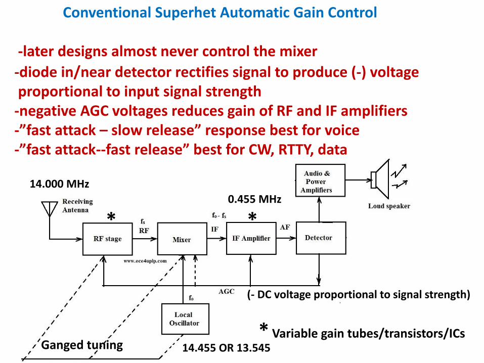
Conventional Superhet Automatic Gain Control
-later designs almost never control the mixer
-diode in/near detector rectifies signal to produce (-) voltageproportional to input signal strength-negative AGC voltages reduces gain of RF and IF amplifiers-”fast attack – slow release” response best for voice-”fast attack--fast release” best for CW, RTTY, data
Ganged tuning
* *
* Variable gain tubes/transistors/ICs
0.455 MHz
14.000 MHz
14.455 OR 13.545
(- DC voltage proportional to signal strength)

AM Demodulation (diode detection)
IF Transformer
RF filter
VoltageAmp PA

Product Detector (really a mixer)
455.0 kHz
456.35 USB
453.65 LSB
455.70 CW
1350 Hz LSB/USB
700 Hz CW
Carrier reinsertion

Beat Frequency Oscillator

Balanced diode ring product detector
BFO frequency removed, but BFO 2nd harmonic is present and must be filtered out
High BFO level injected at T2BFO usually needs buffer to provide enough energy + stability

MC1496: double-balanced product detector/mixer in a chip
-adjustable to fine-balance cancellation of signal and carrier (BFO) RF-no tuned circuits or transformers-great for ham projects!-has gain, so more audio output than diode designs

Audio section of RX can include the following:
-voltage amp. + power amp (PA)
-audio frequency response shaping
-noise limiting (“clipper” or “limiter”)
-noise blanking
-squelch
-audio-derived AGC
-DSP processing (de-noiser, auto-notch, band-pass filters)
-FM de-emphasis

FM Detectors: the ratio detector
Ratio detector
Converts small frequency variations in signal frequency into audio amplitude variations.Speed of amplitude variations becomes audio output frequency.
Very insensitive to AM noise.Precision detector transformer is expensive, so ratio detectors notpopular.

FM quadrature detector
CA3089 chip detector contains amp, limiter, squelch,tuning meter, etc. (big parts count reduction)
Today: complete FM system on chip most common
quadrature coil
Usually10.7 MHz IF


PLL FM detector
No inductors needed: uses free-running osc. and phase detector circuit-phase detector circuit control voltage will follow freq. changein the signal.-control voltage will therefore be a replica of the originalmodulation audio.

FM receivers
-High-gain IF followed by limiter amp. constant amplitude signal, except with very weak signals-LO usually contains frequency multipliers-AM noise of all sorts is eliminated
-at TX high audio freqs. are boosted: pre-emphasis-at RX the highs are de-emphasized to restore normal sound balance

Fixed converter, variable IF superhet
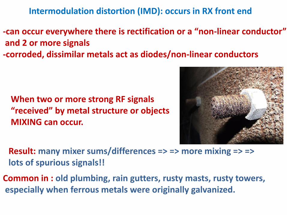
Intermodulation distortion (IMD): occurs in RX front end
-can occur everywhere there is rectification or a “non-linear conductor”and 2 or more signals-corroded, dissimilar metals act as diodes/non-linear conductors
When two or more strong RF signals “received” by metal structure or objectsMIXING can occur.
Result: many mixer sums/differences => => more mixing => => lots of spurious signals!!
Common in : old plumbing, rain gutters, rusty masts, rusty towers,especially when ferrous metals were originally galvanized.
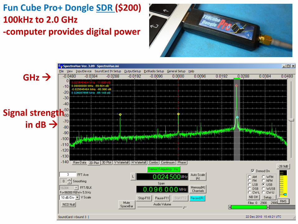
Fun Cube Pro+ Dongle SDR ($200)100kHz to 2.0 GHz-computer provides digital power
GHz
Signal strengthin dB

True digital RX!

End of Receivers!