Embed Size (px)
Citation preview

12 ADVANCED DEEP SEA DIVING EQUIPMENT
William A. Danesi General Electric Company Ocean Systems Programs
Philadelphia, Penn.
INTRODUCTION
As a result of recommendations of several committees convened by the U.S. Navy supervisor of diving for the purpose of reviewing conventional Navy diving equipments, General Electric Company proposed a deep sea diving system development program to the Navy. This program, a proposal for the survey and engineering evaulation of deep sea heavy duty diving equipment, was approved by the Navy on February 2, 1970, and the program was initiated.
The overall goal of this program is to equip the Navy salvage diver with equipment and tools that will enable him to perform work of the same quality and in times approaching that done on the surface.
PAASK V DIVING SYSTEM
Mark V denotes two distinct deep sea diving systems. The air outfit (fig. 12.1) is for heavy duty diving and is issued to vessels and shore activities whose function is to undertake extensive salvage operations. The helium oxygen outfit is a special system issued only to submarine rescue units. The
BREAST - PLATE
Figure 12.1 Deep-sea diving outfit.
203
https://ntrs.nasa.gov/search.jsp?R=19720019468 2018-08-26T09:37:59+00:00Z

deep sea diving outfit consists of the helmet and the dress, which provide water tightness; weights for overcoming positive buoyancy gained by the volume of the helmet and the inflated dress; hoses and control valves for furnishing air; and a nonreturn valve used to prevent seawater from entering and air from escaping from the dress in the event of accidental rupture of the air hose. This Mark V system has been used for many years with remarkable success. In addition to all submarine rescue and salvage work undertaken in peacetime, practically all salvage work of any extent undertaken during World War I1 was accomplished with this equipment. The system is designed for extensive, rugged diving work and provides the diver with maximum physical protection. It is now used in general types of work such as submarine salvage, initial inspection, placing moorings, attaching hose for blowing and venting, ship salvage underwater inspection, internal repairs, installation of patches on ship hulls, construction of dams, harbor work, and other standard industrial and commercial forms of diving. There are also many diving operations undertaken with this equipment in shallow depths in which the rugged equipment provides protection for the diver. It is a fact that today, more than 100 years after its basic development, the “hard hat” diving system is essentially unchanged in form; yet it is still the standard for salvage diving throughout the world.
The Navy standard diving helmet consists of a spun copper helmet with its fittings and a breast plate (fig. 12.2). The interface between the helmet and the breast plate is an interrupted thread breech joint. There are four viewports on the helmet. The one directly in front of the divers face is the faceplate. The faceplate is hinged and held in the closed position by a swing bolt and wing nut. All four ports are protected from breakage by metal guards. Inlet air is controlled by a regulating valve attached to the air supply hose and fixed to the breast plate. A regulating exhaust valve controls the internal pressure of the helmet and the flow of gas from the helmet.
The helmet has many good features that account for the high degree of acceptance throughout the world diving community. However, apart from some modifications in response to advances in technology, until now no overall system study had been undertaken to update the equipment in light of new materials and advances in fabrication technologies, and little attention had been given to new requirements for the function of diving.
PROGRAM TASKS
Figure 12.2 Diving helmet and breast plate.
The overall program was divided into four tasks (fig. 12.3). Initially, a survey was performed to determine the extent of equipment development and the areas where there had been significant improvements in existing equipment. A preliminary system design was evolved with the objective of correcting the deficiencies noted in existing equipment and improving the design to meet the new requirements. In the third task, now in process, sufficient component testing was identified to demonstrate that the system deficiencies could be overcome. This task also includes the final
204

TASK1 - SURVEY AND RECOMMENDATIONS
TASK 2 - PRELIMINARY DESIGN
TASK 3 - CRITICAL COMPONENT TEST
TASK 4 - PROTOTYPE SYSTEM FABRICATION AND TEST
Figure 12.3 Program plan.
WRITTEN QUESTIONNAIRE - 88 OF 150 REPLIED
8 U.S. DIVING COMPANIES
8 U.S. EQUIPMENT MFGRS
10 FRENCH DIVING & MFG
4 GERMAN DIVING & MFG
5 ITALIAN DIVING & MFG
8 BRITISH DIVING & MFG
Figure12.4 Equipment survey.
VISITS:
definition of the recommended
system, by drawings and
specifications. Finally, a proto-
type system is to be fabricated
and delivered to the Navy forevaluation in the field.
EQUIPMENT SURVEY
Two basic objectives were
established for the survey: toachieve sufficient depth to
obtain significant information,
and to obtain a proper interpretation of the
results. An extensive list of divingcompanies and equipment manufacturers
was generated, which included as wide a
range of types of diving as possible. This
was quite difficult in the United States,
since more than 90 percent of the majordiving companies are engaged almost ex-ph_¢i_,plw in cG1 _nct c_ffehc_rp e_nnc_rt divln.
To ensure that the information would be
meaningful, the survey was divided into
phases and activities. Initially, selecteddiving firms were visited to obtain the
information required. The remaining diving
firms were sent a questionnaire. Of 150
companies queries, 88 responded to the
questionnaire (fig. 12.4). Of the total number of commercial divers in the United States, the surveyrecords pertinent diver equipment information from more than 1000 active commercial divers. The
second part of the survey entailed questioning the equipment manufacturers. Their design rationales
were referenced to divers requirements to determine the appropriateness of the design features. The
survey also included a survey of the European diving community. Because of timing andgeographical limitations, the overseas survey was less detailed than the domestic portion, but the
data were essentially complete.
The survey concluded that the most significant and varied developments in heavy duty diving
breathing equipment have occurred in the United States. The advances have been achieved by a
small group of low volume equipment manufacturers at their own initiative and expense. Littletesting of these devices has been done and it is difficult to compare their performance since all have
resulted from different interpretations of the requirements for the designs.
Significant improvements have been made in diver dress in the European diving communityparticularly in the area of heating and in general diver comfort.
The present Mark V diving system, or a modification of it, is the standard equipment for heavy
duty salvage operations throughout the world. There is considerable area for improvement of the
many features of this equipment, however, this improvement must be based on the operationalparameters of the Mark V system.
205

SURVEYRESULTSThe results of the survey are published in reference 1. Since the survey was conducted on a
subjective basis, and since divers, justifiably, have very strong opinions regarding the attributes of
their equipment, the survey sometimes resulted in widely divergent opinions on some features.However, a number of inadequacies in present equipment were identified and efforts were initiated
to correct these situations (fig. 12.5).
• NOISE REDUCTION Nearly all divers complained about excessive noisewithin their helmet and gas system. This did not imply
• IMPROVE RECIRCULATION that they desired all noise eliminated. The psychologicaland safety aspects of hearing gas flowing are quite
• SELF DONNING important. However, a number of divers found itnecessary, when using certain equipment, to turn the gas
• POSITIVE RESERVE GAS supply off to permit communication-a very dangerous
practice.• BETTER MATERIALS
The process of gas circulation and recirculation varied
• LINEAR CONTROL VALVES widely in all of the systems studied. The flow of gas withinthe helmet performs two functions. One is the removal of
• AIR OR MIXED GAS carbon dioxide and replenishment of oxygen, and thesecond is clearing the window ports of moisture to permit
• IMPROVED WEIGHT MATRICES visibility. In the recircular mode of operation described
Figure 12.5 Areas of improvement, later, the ratio of recirculated gas to inlet gas must bemaintained as high as possible, over a range of inlet flows.
The Mark V and many commercial systems are of such weight and complexity that they requirethe assistance of a tender to dress the diver. As diving from habitats increases, the diver must be able
to dress in cramped, confined spaces.The divers prefer the large volume common to the Mark V hehnet because it provides a reserve
should the gas supply be cut off. Almost all divers tell of ration-breathing gas from the helmet in
emergency conditions-a capability unavailable in a mask. However, it takes an exceptionally
trained person to take maximum advantage of this reserve gas.New materials and material fabrication techniques have generally been ignored in most designs of
the diving equipment surveyed. New materials are being used, but they rarely are tailored
specifically to the total application.The control valves were mainly selected from those available at standard valve suppliers.
However, very few commercially available valves are required to control precisely over both a wide
range of flows and a fairly wide range of inlet pressures.The Mark V system for air is considerably different, lighter, and much less cumbersome, than the
system for mixed gas operation. Most commercially available mixed gas helmets can be used for air
operation but not the converse. No single helmet was found that was designed to operate efficiently
with both gas combinations.Significant areas of improvement were identified for the allocation and positioning of weights to
control buoyancy and mass properties of the diver in the water and yet allow him mobility on thesurface.
From the results of this survey and an assessment of the areas of required improvement a system
design requirement was generated (fig. 1 2.6). The first four parameters delineate the conventional
diving environment. The last seven are goals to be achieved in a single diving system design. It was
206
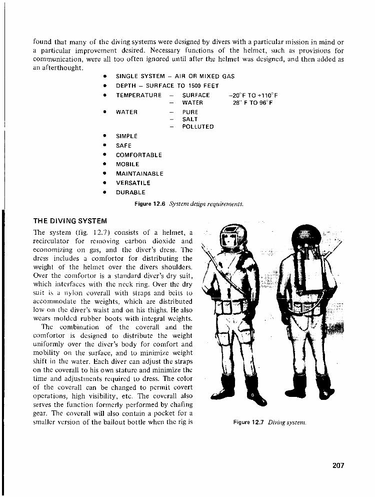
found that many of the diving systems were designed by divers with a particular mission in mind or
a particular improvement desired. Necessary functions of the helmet, such as provisions forcommunication, were all too often ignored until after the helmet was designed, and then added as
an afterthought.SINGLE SYSTEM - AIR OR MIXED GAS
DEPTH - SURFACE TO 1500 FEET
TEMPERATURE
• WATER
- SURFACE -20°F TO +110°F
- WATER 28 ° F TO 96°F
- PURE
- SALT- POLLUTED
• SIMPLE
• SAFE
• COMFORTABLE
• MOBILE
• MAINTAINABLE
• VERSATILE
• DURABLE
Figure 12.6 System design requirements.
THE DIVING SYSTEM
The system (fig. 12.7) consists of a helmet, a
recirculator for removing carbon dioxide and
economizing on gas, and the diver's dress. The
dress includes a comfortor for distributing the
weight of the helmet over the divers shoulders.
Over the comfortor is a standard diver's dry suit,
which interfaces with the neck ring. Over the dry
suit is a nylon coverall with straps and belts to
accommodate the weights, which are distributed
low on the diver's waist and on his thighs. He alsowears molded rubber boots with integral weights.
The combination of the coverall and the
comfortor is designed to distribute the weight
uniformly over the diver's body for comfort and
mobility on the surface, and to minimize weight
shift in the water. Each diver can adjust the strapson the coverall to his own stature and minimize the
time and adjustments required to dress. The color
of the coverall can be changed to permit covert
operations, high visibility, etc. The coverall also
serves the function formerly performed by chafing
gear. The coverall will also contain a pocket for asmaller version of the bailout bottle when the rig is Figure 12.7 Diving system.
207

used for air diving. Weights are placed in the pocket and can be varied according to the dress and
support equipment.
Thc rccirculator is covcrcd by a shroud to minimize hydrodynamic drag if the diver is in strong
currents or moving about. It is, however, not a swimmable system as such. The shoes are rubber
with steel foot and toe protection. The foot pad is corrugated rubber and has a definite breakpoint
to permit foot movement while walking on rough or slippery surfaces.
The diver dons his insulated undergarment and places the comfort ring on his shoulders. He then
enters his dry suit with the neck ring already attached. The dry suit has a back entry with a
waterproof zipper. The diver then puts on his coveralls and attaches the cinch cables on the neck
ring. Finally, he adjusts his cable and belt tensions to the required fit. At this point, he may have his
weights in place or not, depending on his desire for mobility. Just before the dive he places his
helmet in position, rotates it, and locks. He is ready now to dive.
The system is designed to be compatible with all types of swim dress (fig. 12.8). The interface in
all instances is the neck ring. If the user dives without a suit, a conventional neck seal is attached to
the neck ring at the same interface.
WEIGHT 26.83 LBS
• DRY SUIT VOLUME (TOTAL) 0.67 FT 3
VOLUME (FREE) 0.57 FT 3
• CONSTANT VOLUME SUIT BUOYANCY 16 LBS POSITIVE
• WET SUIT FLOW-AIR 0-140 _/MIN (5 FT3/MIN)- MIXED GAS 0-140 _/MIN (5 FT3/MIN)
• NO SUIT CONTROL VALVE 3 TURN-NEEDLE
SOUND LEVEL < 90 db• ADVANCED SUITS
WINDOWS 3/16" LEXAN
• HEATED MATERIALS:
SHELL GLASS EPOXY• SUPER INSULATIVE BREECH 316 SS
VALVES PLATED BRASS
Figure 12.8 Diver dress compatibility. Figure 12.9 Helmet.
The design of the helmet (fig. 12.9) and recirculator will be covered in some detail because they
are the major factors affecting the ability to provide a system that meets the goals of the program.
The helmet weight selection is based on several factors, particularly the tradeoff of handling and
inertia against buoyancy considerations. The center of gravity and center of buoyancy must be
maintained at the same point so that when the diver moves his head underwater the helmet will
follow his movement, not resist. The volume of the helmet is sufficient to permit head movement,
both to reduce fatigue and to take advantage of the window position, particularly that of the top
window. Airflows are compatible with the acceptable values for minimizing the collection of carbon
dioxide in dead areas. The inlet valve will allow linear control of the flow evenly across the three
turns. Sound levels are set by acoustic standards to permit 8 hr of work without fatigue or
irritation.
208

SYSTEM OPERATION
Taking a front view of the helmet (fig.
12.10), the inlet air control is on the left
(diver's right) and the exhaust control on
the right. The diver has easy access to thevalves even when the suit is inflated. The
valves are snagproof yet have positive grip
profiles. The window is easily removable
when scratched or damaged. The
communications interface is just below the [window in a recess especially provided to
keep the pickup out of the air stream.
When operating open cycle (fig. 1 2.1 1)
the gas flows from the inlet fitting to the
control valve in a tube along the inner wall
of the helmet. Expansion chambers are
provided for muffling and acoustic dead-
ening. A distributor with a sintered metalfilter reduces inlet air noise and flows the
o_c 11nifnrrnhz nern_ the windc_w for.............. j ................
moisture removal. All plumbing for the
open-cycle operation is easily removable
for maintenance and cleaning and is
fabricated from standard parts where possible. The
sintered filter is removable for easy cleaning and
replacement.
When the recirculator is in operation (fig.
12.1 2), gas is gradually expanded after it enters the
helmet. The gas progresses across the window and
enters the circulator inlet tube. As this gas leaves
the helmet it passes through a venturi, whichaspirates gas from the perforated tube in the
bottom of the helmet. Thus, any carbon dioxide
accumulating near the neck ring is swept out intothe scrubber.
The comfortor supports the neck ring but is not
directly attached (fig. 12.13). When the diver
enters the water the helmet is likely to float afraction of an inch above the comfort ring (fig.
12.14).The recirculator consists of a scrubber to remove
carbon dioxide, an inlet to receive the mix gas
supply and trap the excess water, a venturi to
recirculate and mix the gas from the scrubber with
the inlet gas, and connection fittings to the helmet
hoses (fig. 1 2.15). An expansion chamber above
the venturi is designed to minimize noise
! ® ® ® ® _\
\ ,/
Figure 12.10 Front view of helmet.
/
Figure 12.11 Flow pattern open cycle.
209

BBER
Figure 12.12 Flow pattern recirculator. Figure 12.13 6bin fort ring.
HARD RUBBERBREAST PLATE
NECK_HELMETECH RING
I_BREAST PLATE
Figure 12.14 Comfort ring attached.
210
VALVES
RECIRC. OPEN
GAS INLET CLOSED
EXHAUST CRACKED
" K" VALVE CLOSED
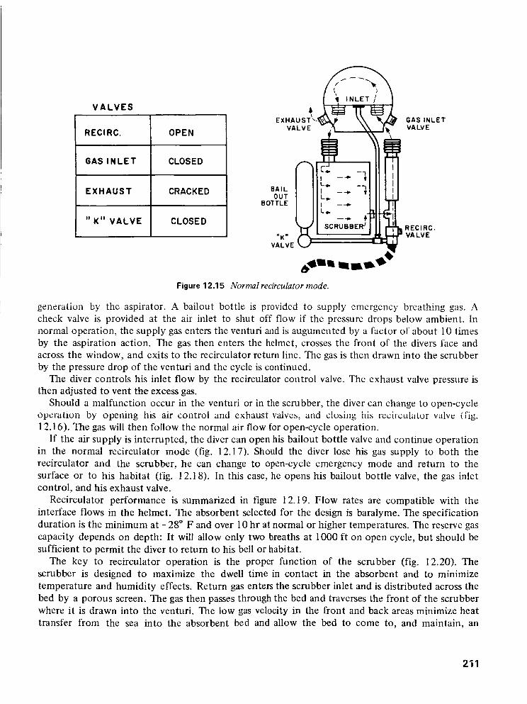
Figure 12.15 Normal recirculator mode.
GAS INLETVALVE
RECIRC.VA LV E
generation by tile aspirator. A bailout bottle is providcd to supply emergency breathing gas. A
check valve is provided at the air inlet to shut off flow if the pressure drops below ambient. In
normal operation, the supply gas enters the ventufi and is augumented by a factor of about 10 times
by the aspiration action. The gas then enters the helmet, crosses the front of the divers face and
across the window, and exits to the recirculator return line. The gas is then drawn into the scrubber
by the pressure drop of the venturi and the cycle is continued.
The diver controls his inlet flow by the recirculator control valve. The exhaust valve pressure is
then adjusted to vent the excess gas.
Should a malfunction occur in the venturi or in the scrubber, the diver can change to open-cycle
operation by opening his air control and exhaust valves, and closing hi_ recirculator valv_ (fig.
12.16). The gas will then follow the normal air flow for open-cycle operation.
If the air supply is interrupted, the diver can open his bailout bottle valve and continue operation
in the normal recirculator mode (fig. 12.17). Should the diver lose his gas supply to both the
recirculator and the scrubber, he can change to open-cycle emergency mode and return to the
surface or to his habitat (fig. 12.18). In this case, he opens his bailout bottle valve, the gas inlet
control, and his exhaust valve.
Recirculator performance is summarized in figure 12.19. Flow rates are compatible with the
interface flows in the helmet. The absorbent selected for the design is baralyme. The specification
duration is the minimum at - 28 ° F and over 10 hr at normal or higher temperatures. The reserve gas
capacity depends on depth: It will allow only two breaths at 1000 ft on open cycle, but should be
sufficient to permit the diver to return to his bell or habitat.
The key to recirculator operation is the proper function of the scrubber (fig. 12.20). The
scrubber is designed to maximize the dwell time in contact in the absorbent and to minimize
temperature and humidity effects. Return gas enters the scrubber inlet and is distributed across the
bed by a porous screen. The gas then passes through the bed and traverses the front of the scrubber
where it is drawn into the venturi. The low gas velocity in the front and back areas minimize heat
transfer from the sea into the absorbent bed and allow the bed to come to, and maintain, an
211

VALVES
REClRC. CLOSED
GAS INLET OPEN
EXHAUST OPEN
" K '° VALVE CLOSEDBOTTLE I J
SCRUBBER [_B
GAS iNLETVALVE
RECIRC.VA LV E
Figure 12.16 Open cycle (surface).
VALVES
RECIRC. OPEN
GAS INLET CLOSED
EXHAUST CRACKED
" K" VALVE OPEN
BAILOUT
BOTTLE
"K"
VALVE
VALVE
GAS INLETVALVE
RECIRC.VA LV E
Figure 12.17 Emergen O, recirculator.
212

VALVES
RECIRCo CLOSED
GAS INLET OPEN
EXHAUST CRACKED
" K" VALVE OPEN
BAILOUT
BOTTLE
GAS INLETVALVE
RECIRC.VA LV E
WEIGHT
BUOYANCY
FLOW -- INLET
RECI RCULATION
GAS _iLET
SEE DETAIL
' L
k_.
SEE DETAIL 'D'-
Figure 12.18 Emergency open cycle.
45 LBS. RECIRCULATION RATIO
NEUTRAL ABSORBANT
0-14 _/MIN DURATION
0-140_/MIN RESERVE GAS
Figure 12.19 Recirculator.
/--- SCRUBBER
GAS INLET ---.._ / / BARALYME
BAILOUT _"* -_ -_ -_ --t_f_,....---"V EN T UR IBOTTLE
h--- _o.o _'IGAS EXIT
tT"_ 'A"._
J
!,,,J
T VENTURI
16.0"
_LMAX BARALYME CAPACITY=320 IN 3
2.0_=
,Jr
Figure 12.20 Scrubber.
>10:1
BARALYME
4-6 HOURS
18 S. CU. FT.
I-- BARALYME
SECT A-A
213

optimum operating temperature.The scrubber inlet has a trap toremove moisture from either tile
helmet or the breathing gas (fig.
12.21). The trap prevents this
moisture from entering the plenum
occupied by the porous filter, and
prevents clogging of the filter bymoisture.
Water is collected in the lower
collection tube and kept in place by
a simple labyrinth design (fig.
12.22). The accumulated water
may be drawn off on the surface by
removal of the end cap.
The scrubber is designed to beconstructed simply and
economically (fig. 12.23). A singlemultichannel extrusion forms four
GAS INLET
SCRUBBER
'c'L J'c'
DETAIL'B'
WELD /
BARALYME --
INSULATOR
S FLOW
IS SIMILAR)
Figure 12.21 Scrubber inlet details.
of the sides providing flanges, holders for the porous plates, and guards to prevent bypass of gases
through the bed.The scrubber shown is a test scrubber to permit sizing of the bed and optimizing operational
parameters. Exact dimension and design of this and other parts will be completed when the
component test is completed.
FILTERSCRUBBER CANISTER _
\ _ _ GAS BAFFLE
WELD
PLATE SEAL W
II ' / CANISTER BTM
_ ___ _._. DR:TU_BE PLATE
WATER COLL.TUBE _ SECT L-L
REMOVABLECAP \FOR DRAINING
Figure 12.22 Method for water collection.
214

Figure 12.23 Parts of the scrubber.
PROGRAM STATUS
The status of the program is shown in figure 12.24. It is expected that the prototype system will be
available for swimming in early 1972.
• COMPLETED WORLD-WIDE SURVEY AND REPORT
• STARTING CRITICAL COMPONENT TEST PHASE TO INCLUDE
• ACOUSTIC TESTING
• RECIRCULATOR CO 2 SCRUBBING TESTS
• GAS INLET AND EXHAUST VALVE EVALUATIONTESTS
• NEXT PHASE TO BUILD TEST AND DELIVER THREE (3)ENGINEERING PROTOTYPES
Figure 12.24 Program status.
REFERENCE
1. Anon: Research Report 12-70. U.S. Navy Supervisor of Diving, Nov. 15, 1970.
215