Embed Size (px)
Citation preview

1
Subject code-PCI7D002
ADVANCED DESIGN OF REINFORCED
CONCRETE STRUCTURES
Module-I
Submitted By:
Sushree Kiran Samal
Faculty
Department of Civil Engineering
Government College of Engineering, Keonjhar

2
SYLLABUS
Module-I - Earthquake Engineering
➢ Introduction to Earthquake Engineering
➢ Cyclic behaviour of concrete and reinforcement
➢ Computation of earthquake forces on building frame using Seismic Coefficient Method as per IS
1893-2002
➢ Base shear and storey shear calculation for multi-storeyed building frames
➢ Significance of ductility
➢ Ductility of beam
➢ Design and detailing for ductility
➢ Simple problems based on above concept as per is 13920
Module-II - Retaining walls
➢ Retaining walls
➢ Forces acting on retaining wall
➢ Stability requirement
➢ Design of Cantilever and Counterfort Retaining walls
Module-III - Bridges
➢ Introduction to bridges:
• Classification and components of a standard bridge
• Economical span
• Location of piers and abutments
• Vertical clearance above HFL
• Scour depth
• Choice of bridge type
➢ Standard Loadings for Road Bridges, Impact effect and impact factor calculation for RCC and steel
bridges
➢ Design of single vent rectangular slab culvert
Module-IV- Foundations
➢ Design of Foundations:
• Design of Rectangular and Trapezoidal Combined footing

3
References for Module-I
1. A. K. Jain, “Reinforced Concrete: Limit State Design”, Nem Chand Brothers, Roorkee, 7th
edition, 2016.
2. B.C. Punmia, A. K. Jain and A. K. Jain, “Limit state design of reinforced concrete (As per IS 456
: 2000)”, Laxmi Publications, 2016.
3. C.V.R. Murthy, Rupen Goswami, A.R. Vijayanarayanan, Vipul V Mehta, Some Concepts in
Earthquake Behaviour of Buildings, Gujarat State Disaster Management Authority, Govt. Of
Gujarat, 2014.
4. S. K. Duggal, “Earthquake-Resistant Design of Structures”, Oxford University Press, 2nd edition,
2017.

4
Detailed Course of Module-I
Sl. No. Module Lecture
No. Content
1
I
1 Introduction to Earthquake Engineering
2 2 Earthquake-resistant Buildings
3 3 Cyclic behaviour of concrete and reinforcement
4
4 Computation of earthquake forces on building frame using
Seismic Coefficient Method as per IS 1893-2002
(Base shear and storey shear calculation for multi-storeyed
building frames)
5
5 Significance of ductility
Ductility of beam
Design and detailing for ductility
Simple problems based on above concept as per is 13920
5
LECTURE – 1 INTRODUCTION TO EARTHQUAKE ENGINEERING

6
1. INTRODUCTION TO EARTHQUAKE ENGINEERING
1.1. EARTHQUAKE ENGINEERING
• Earthquake engineering is a branch of engineering that deals in designing and analyzing
structures subjected to seismic loading.
• The effects of earthquakes on people and their environment and methods of reducing those effects
are included in the earthquake engineering.
• Aim of earthquake engineering is to properly design and construct the structures in accordance
with building codes, so as to minimize damage due to earthquakes.
1.2. EARTHQUAKE
• Earthquake is defined as, ‘Ground shaking and radiated seismic energy caused mostly by sudden
slip on a fault, volcanic or any sudden stress change in the earth’.
• An earthquake is the sudden shaking of the ground caused by the passage of seismic waves
through Earth's rocks.
Fig.1.1. Building knocked off its foundation by the January 1995 earthquake in Kobe, Japan
Fig. 1.2. Effects of earthquake Fig. 1.3. Strike-slip fault

7
1.3. TERMS RELATED TO EARTHQUAKE
Seismology:
• Seismology is the study of the generation, propagation and measurement of seismic waves
through earth and the sources that generate them.
• Seismology is the branch of geophysics which deals with the occurrence of earthquakes and
related phenomena on the planet earth.
Hypocenter or Focus:
• An earthquake is generally due to some disturbance or displacement in the rocks at some depth
below the surface of the Earth.
• Shock waves originate from that place or point of disturbance and then travel in all directions
causing the vibrations.
• The place or point of origin of an earthquake in the interior of the earth is known as focus or
hypocenter (Fig. 1.4).
• In modern seismology, focus signifies a zone rather than a point of origin. It may lie from a few
hundred meters to hundreds of kilometres below the surface.
Epicenter:
• The point or place on the surface vertically above the focus of a particular earthquake is termed
as its epicentre (Fig. 1.4).
• It is that (geographical) place on the surface of the earth where the vibration from a particular
earthquake reaches first of all.
• It is often the location of maximum damage in that event.
Fig. 1.4. Focus and epicentre of an earthquake

8
Magnitude:
• Magnitude is the term expressing the rating of an earthquake on the basis of amplitude of seismic
waves recorded as seismograms.
• The method (of determining rating of an earthquake) was first used by Charles F Richter in 1935
who developed a scale of magnitude for local use on the basis of study of records of earthquakes
of California, USA.
• Subsequently that scale was improved upon and is presently used internationally for describing
the size of an earthquake.
• In precise terms and as understood today, the Richter Magnitude is the logarithm to the base of
10 of the maximum seismic wave amplitude recorded on a seismograph at a distance of 100 km
from the epicentre of a particular earthquake.
Intensity:
• Intensity is the rating of the effects of an earthquake at a particular place based on the
observations of the affected areas, using a descriptive scale like Modified Mercalli Scale.

9
LECTURE – 2 EARTHQUAKE-RESISTANT BUILDINGS

10
2. EARTHQUAKE-RESISTANT BUILDINGS
2.1 DYNAMIC ACTIONS ON BUILDINGS – WIND versus EARTHQUAKE
• Dynamic actions are caused on buildings by both wind and earthquakes. But, design for wind
forces and for earthquake effects are distinctly different.
• The intuitive philosophy of structural design uses force as the basis, which is consistent in wind
design, wherein the building is subjected to a pressure on its exposed surface area; this is force-
type loading.
• However, in earthquake design, the building is subjected to random motion of the ground at its
base (Fig. 2.1), which induces inertia forces in the building that in turn cause stresses; this is
displacement-type loading.
• Another way of expressing this difference is through the load-deformation curve of the building
– the demand on the building is force (i.e., vertical axis) in force-type loading imposed by wind
pressure, and displacement (i.e., horizontal axis) in displacement-type loading imposed by
earthquake shaking.
• Wind force on the building has a non-zero mean component superposed with a relatively small
oscillating component (Fig. 2.2).
• Thus, under wind forces, the building may experience small fluctuations in the stress field, but
reversal of stresses occurs only when the direction of wind reverses, which happens only over a
large duration of time.
Fig. 2.1. Difference in the design effects on a building during natural actions of (a) Earthquake Ground Movement at base, and (b) Wind Pressure on exposed area

11
• On the other hand, the motion of the ground during the earthquake is cyclic about the neutral
position of the structure.
• Thus, the stresses in the building due to seismic actions undergo many complete reversals and
that too over the small duration of earthquake.
2.2. BASIC ASPECTS OF SEISMIC DESIGN
• The mass of the building being designed controls seismic design in addition to the building
stiffness, because earthquake induces inertia forces that are proportional to the building mass.
• Designing buildings to behave elastically during earthquakes without damage may render the
project economically unviable.
• As a consequence, it may be necessary for the structure to undergo damage and thereby dissipate
the energy input to it during the earthquake.
• Therefore, the performance criteria (earthquake resistant design philosophy) implicit in most
earthquake codal provisions (Jain 1980, 1996, IS:1893, IBC 2006) require that structure should
be able to resist (Fig. 2.3):
(a) earthquakes of minor (and frequent) intensity with no damage to structural and non-
structural elements. A structure would be expected to resist such frequent but minor shocks within
its elastic range of stresses;
(b) earthquakes of moderate intensity with minor damage to structural elements, and some
damage to non-structural elements. With proper design and construction, it is believed that
structural damage due to the majority of earthquakes will be limited to repairable damage; and
(c) earthquakes of severe (and infrequent) intensity with damage to structural elements, but
with no collapse (to save life and property inside/adjoining the building). Severe structural
damage is expected.
Fig. 2.2. Nature of temporal variations of design actions: (a) Earthquake Ground Motion – zero mean, cyclic, and (b) Wind Pressure – non-zero mean, oscillatory

12
Table 2.1. Seismic design criteria
Earthquake Desired behaviour Controlling parameter
Minor No damage to structural components Control deflection by providing
stiffness
Moderate
No significant structural damage, minor
cracks in beams and columns, Response
should be predominantly elastic
Avoid yielding of members or
permanent damage by providing
strength
Severe,
Catastrophic
No collapse of the system which could
cause loss of life
Allow structure to enter into
inelastic range and absorb energy
by providing ductility
• Therefore, buildings are designed only for a fraction (~8-14%) of the force that they would
experience, if they were designed to remain elastic during the expected strong ground shaking,
and thereby permitting damage.
• But, sufficient initial stiffness is required to be ensured to avoid structural damage under minor
shaking.
• Thus, seismic design balances reduced cost and acceptable damage, to make the project viable.
• This careful balance is arrived based on extensive research and detailed post-earthquake damage
assessment studies.
• A wealth of this information is translated into precise seismic design provisions. In contrast,
structural damage is not acceptable under design wind forces.
Fig. 2.3. Earthquake-Resistant Design Philosophy for buildings: (a) Minor (Frequent) Shaking – No/Hardly any damage, (b) Moderate Shaking – Minor structural damage, and some non-structural damage, and (c) Severe (Infrequent) Shaking – Structural damage, but no collapse

13
• For this reason, design against earthquake effects is called as earthquake-resistant design and
not earthquake-proof design.
2.3. THE FOUR VIRTUES OF EARTHQUAKE RESISTANT BUILDINGS
For a building to perform satisfactorily during earthquakes, it must meet the philosophy of earthquake-
resistant design discussed in Section 2.2.
2.3.1 Characteristics of Buildings
• There are four aspects of buildings that architects and design engineers work with to create the
earthquake-resistant design of a building, namely seismic structural configuration, lateral
stiffness, lateral strength and ductility, in addition to other aspects like form, aesthetics,
functionality and comfort of building.
• Lateral stiffness, lateral strength and ductility of buildings can be ensured by strictly
following most seismic design codes.
• But, good seismic structural configuration can be ensured by following coherent architectural
features that result in good structural behaviour.
(i) Seismic Structural Configuration
Seismic structural configuration entails three main aspects, namely
(a) geometry, shape and size of the building,
(b) location and size of structural elements, and
(c) location and size of significant non-structural elements (Fig. 2.4).
Fig. 2.4. Components of seismic structural configuration: (a) overall geometry, (b) structural elements (e.g., moment resisting frames and structural walls), and (c) significant non-structural elements (e.g., façade glass)

14
• Buildings can be placed in two categories, namely simple and complex (Fig. 2.5).
• Buildings with rectangular plans and straight elevation stand the best chance of doing well during
an earthquake, because inertia forces are transferred without having to bend due to the geometry
of the building (Fig. 2.5a).
• But, buildings with setbacks and central openings offer geometric constraint to the flow of inertia
forces; these inertia force paths have to bend before reaching the ground (Fig. 2.5b, 2.5c).
Fig. 2.5. Classification of buildings: (a) Simple, and (b), (c) Complex

15
(ii) Structural Stiffness, Strength and Ductility
• The next three overall properties of a building, namely lateral stiffness, lateral strength and
ductility, are illustrated in Fig. 2.6, through the lateral load - lateral deformation curve of the
building.
• Lateral stiffness refers to the initial stiffness of the building, even though stiffness of the building
reduces with increasing damage.
• Lateral strength refers to the maximum resistance that the building offers during its entire history
of resistance to relative deformation.
• Ductility towards lateral deformation refers the ratio of the maximum deformation and the
idealised yield deformation.
• The maximum deformation corresponds to the maximum deformation sustained by it, if the load-
deformation curve does not drop, and to 85% of the ultimate load on the dropping side of the
load-deformation response curve after the peak strength or the lateral strength is reached, if the
load-deformation curve does drop after reaching peak strength.
Fig. 2.6: Structural Characteristics: Overall load deformation curves of a building, indicating (a) lateral stiffness, (b) lateral strength, and (c) ductility towards lateral deformation

16
2.3.2 What are the Four Virtues?
• All buildings are vertical cantilevers projecting out from the earth’s surface.
• Hence, when the earth shakes, these cantilevers experience whiplash effects, especially when the
shaking is violent. Hence, special care is required to protect them from this jerky movement.
• Buildings intended to be earthquake-resistant have competing demands.
• Firstly, buildings become expensive, if designed not to sustain any damage during strong
earthquake shaking.
• Secondly, they should be strong enough to not sustain any damage during weak earthquake
shaking.
• Thirdly, they should be stiff enough to not swing too much, even during weak earthquakes.
• And, fourthly, they should not collapse during the expected strong earthquake shaking to be
sustained by them even with significant structural damage.
• These competing demands are accommodated in buildings intended to be earthquake resistant by
incorporating four desirable characteristics in them.
• These characteristics, called the four virtues of earthquake-resistant buildings, are:
i. Good seismic configuration, with no choices of architectural form of the building that is
detrimental to good earthquake performance and that does not introduce newer complexities in
the building behaviour than what the earthquake is already imposing;
ii. At least a minimum lateral stiffness in each of its plan directions (uniformly distributed in
both plan directions of the building), so that there is no discomfort to occupants of the building
and no damage to contents of the building;
iii. At least a minimum lateral strength in each of its plan directions (uniformly distributed in
both plan directions of the building), to resist low intensity ground shaking with no damage,
and not too strong to keep the cost of construction in check, along with a minimum vertical
strength to be able to continue to support the gravity load and thereby prevent collapse under
strong earthquake shaking; and
iv. Good overall ductility in it to accommodate the imposed lateral deformation between the base
and the roof of the building, along with the desired mechanism of behaviour at ultimate stage.
• Behaviour of buildings during earthquakes depend critically on these four virtues. Even if any
one of these is not ensured, the performance of the building is expected to be poor.
17
2.3.3 Who controls the Four Virtues?
• Both the architect and the engineer work together to create the best design with good interaction
at all stages of the process of the design of the building.
• Here, the architect brings in perspectives related to form, functionality, aesthetics and contents,
while the engineer brings the perspectives of safety and desired earthquake performance during
an expected earthquake.
2.3.4 How to achieve the Four Virtues?
• The four virtues are achieved by inputs provided at all stages of the development of the building,
namely planning, design, construction and maintenance.
• Each building to be built is only one of the kind ever, and no research and testing is performed on
that building, unlike factory made products like aircrafts, ships and cars.
• The owner of the building trusts the professionals (i.e., architect and engineer) to have done due
diligence to design and construct the building.
• Thus, professional experience is essential to be able to conduct a safe design of the building,
because it affects the safety of persons and property.
➢ Traditionally, in countries that have advanced earthquake safety initiatives, governments have
played critical role through the enforcement of techno-legal regime, wherein the municipal
authorities arrange to examine, if all requisite technical inputs have been met with to ensure
safety in the building, before allowing the building to be built, the construction to be continued
at different stages for the users to occupy the building.
➢ These stages are: (1) conceptual design stage, (2) design development stage through peer
review of the structural design, (3) construction stage through quality control and quality
assurance procedures put in place.
➢ Senior professionals (both architects and engineers) are required to head the team of professionals
to design a building; these senior professionals should have past experience of having designed
buildings to resist strong earthquakes under the tutelage of erstwhile senior professionals.
2.4. STRUCTURAL SYSTEMS
• A building is subjected to gravity loads such as dead loads and live loads, and lateral loads such
as wind or earthquake loads.
• These loads are required to be transferred safely to the soil below through a system of
interconnected structural members.

18
• Connections between beam and column or beam, column and wall or bracing member may be
simple or moment resistant based on economy or other practical considerations.
• In tall buildings, the biggest challenge comes from satisfying the serviceability limit state,
constructability, durability as well as economy.
• A structural system needs to be evolved to satisfy all the preceding requirements of the structure.
❖ Gravity load resisting system
Purpose- To transfer gravity loads applied at floor levels down to the foundation level
➢ Direct Path Systems
o Slab supported on load bearing walls
o Slab supported on columns
➢ Indirect Multi Path Systems
o Slab supported on beams
o Beams supported on other beams
o Beams supported on walls or columns
❖ Lateral load resisting system
Purpose- To transfer lateral loads applied at any location in the structure down to the foundation
level.
➢ Single System
o Moment resisting frames
o Braced frames
o Shear walls
o Tubular systems
➢ Dual System
o Shear wall-frames
o Tube + frame + shear wall
• A structural system may be classified as follows:
i. Load bearing wall system
ii. Moment resisting frame system
iii. Flexural (shear) wall
iv. Dual frame system
v. Tube system

19
i. Load bearing wall system
▪ It is a system which is designed for gravity as well as for lateral loads.
▪ Under lateral loads the walls act like cantilevers.
▪ The walls and partition wall supply in-plane lateral stiffness and stability to resist wind and
earthquake loading.
▪ This system lacks in providing redundancy for the vertical and lateral load supports, i.e. if a wall
fails, the vertical loads as well as lateral loads carrying capacity is eliminated leading to instability.
▪ Clause 8.2.1 of IS: 4326-1993 restricts the use of such structural systems to 3 storeys in seismic
zone V and 4 storeys in other zones.
ii. Moment resisting frame system
• It is a system in which beams, columns and joints are capable of resisting vertical and lateral
loads, primarily by flexure.
• The beam-column joint is the most crucial component. The moment distribution among beams
and columns takes place through joints. If a beam-column joint fails, the whole structural system
will fail.
• In a moment resisting frame, relative stiffness of beams and columns is very important.
• A frame may be designed as having weak column-strong beam proportions or strong column-
weak column proportions.
• Under lateral loads, the failure mechanism in two types of frames are shown in the Fig. 2.7.
• A plastic hinge will form at the ends of a column or a beam depending upon which is weaker.
• The reasons for having strong column-weak beam arrangement are:
o Failure of a column means the collapse of the entire building.
o In a weak-column structure, plastic deformation is concentrated in a particular storey, as
shown in Fig. 2.7(b), and a relatively large ductility factor is required.
o In both shear and flexural failure of columns, degradations are greater than those in the
yielding of beams.

20
• Types of moment resisting space frames
o Ordinary moment resisting frame - It is a space frame capable of carrying all vertical
and horizontal loads, by developing bending moments in the members and at joints, but
not meeting the special detailing requirements for ductile behavior.
o Ductile/ Special moment resisting frame - It is a moment resisting frame detailed to
provide ductile behaviour and comply with the requirements given in IS 4326 or IS 13920
or SP 6. A frame of continuous construction comprising flexural members and columns
designed and detailed to accommodate reversible lateral displacements after the formation
of plastic hinges (without the decrease in strength) is known as ductile moment resisting
frame.
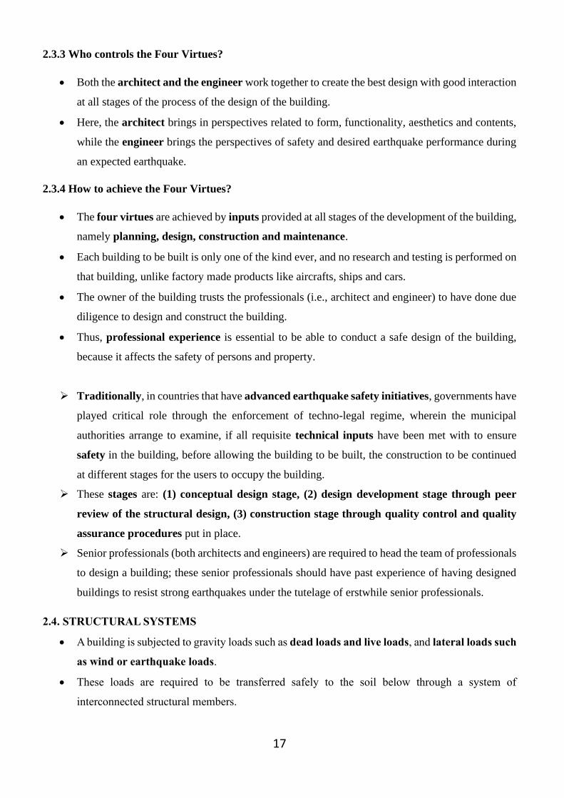
iii. Flexural (shear) wall
• It is a reinforced concrete wall designed to resist lateral forces in its own plane.
• Shear walls (Fig. 2.8.) are reinforced concrete walls cantilevering vertically from the base (i.e.
foundations) designed and detailed to be ductile so as to resist seismic forces and to dissipate
energy through flexural yielding at one or more plastic hinges.
• Shear walls should extend from foundations either to the top of the building or to a lesser height
as required from the design consideration.
• Studies show that shear walls of height about 85 percent of total height of building are
advantageous.
Fig. 2.7. Failure mechanisms in rigid frame
21
• A shear wall building is normally quite rigid as compared to a frame structure.
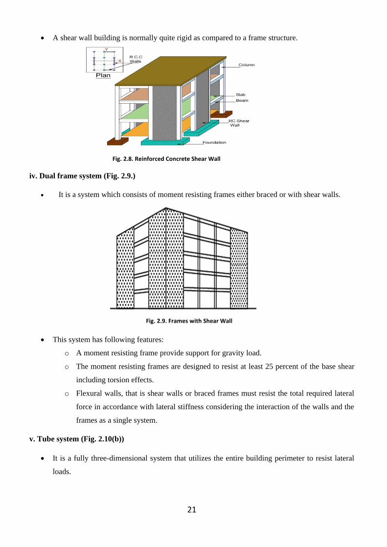
iv. Dual frame system (Fig. 2.9.)
• It is a system which consists of moment resisting frames either braced or with shear walls.
• This system has following features:
o A moment resisting frame provide support for gravity load.
o The moment resisting frames are designed to resist at least 25 percent of the base shear
including torsion effects.
o Flexural walls, that is shear walls or braced frames must resist the total required lateral
force in accordance with lateral stiffness considering the interaction of the walls and the
frames as a single system.
v. Tube system (Fig. 2.10(b))
• It is a fully three-dimensional system that utilizes the entire building perimeter to resist lateral
loads.
Fig. 2.8. Reinforced Concrete Shear Wall
Fig. 2.9. Frames with Shear Wall

22
• It is a structural system consisting of closely spaced exterior columns tied at each floor level with
relatively deep spandrel beams. Thus, it creates the effect of a hollow concrete tube perforated by
openings for the windows.
• The exterior columns are generally spaced between 1.25 m to 3 m.
• The spandrel beams interconnecting the closely spaced columns have a depth varying from 60
cm to 1.25 m and width varying from 25 cm to 1 m.
• This system is very effective in controlling the lateral displacements in very tall buildings.
• Three basic types of tube structures are shown in Fig. 2.11.
Fig. 2-10. (a) Traditional Frame System with a central core, and (b) Tube System
Fig. 2.11. Three basic types of tube systems

23
LECTURE – 3 CYCLIC BEHAVIOUR OF CONCRETE AND REINFORCEMENT

24
3. CYCLIC BEHAVIOUR OF CONCRETE AND REINFORCEMENT
3.1. BRITTLE AND DUCTILE BEHAVIOUR OF MATERIALS
• The term ductility implies the ability of a material to sustain significant deformation prior
to collapse.
• A brittle material is the one that fails suddenly upon attaining the maximum load.
• Typical force-deformation relationships for brittle and ductile materials are shown in fig.
3.1.
3.2. CYCLIC BEHAVIOUR OF PLAIN CONCRETE
• Plain concrete comes under the category of brittle materials.
• During the first cycle, the stress strain curve is the same as that obtained from static tests. If
the specimen is unloaded and reloaded in compression, stress strain curves similar to those
shown in fig. 3.2. are obtained.
• It can be seen that slope of the stress strain curves as well as the maximum attainable stress
decrease with the number of cycles. Thus, the stress strain relationship for plain concrete
subjected to repeated compressive loads is cycle dependent.
• The decrease in stiffness and strength of plain concrete is due to the formation of cracks.
• The compressive strength of concrete depends on the rate of loading. As the rate of loading
increases, the compressive strength of concrete increases but the strain at the maximum
stress decreases.
• Plain concrete cannot be subjected to repeated tensile loads since its tensile strength is
practically zero.
Fig. 3.1. Brittle and ductile force-deformation behaviour

25
3.3. CYCLIC BEHAVIOUR OF REINFORCING STEEL
• Reinforcing steel has much more ductility than plain concrete.
• The ultimate strain in mild steel is of the order of 25% whereas, in concrete it is of the order
of 0.3%.
• In the first cycle, the reinforcing steel shows stress strain curve similar to that obtained in
the static test. After the specimen has reached its yield level and direction of load is reversed,
Fig. 3.2. Plain concrete section under repeated compressive loading
Fig. 3.3. Hysteresis behaviour of reinforcing steel

26
that is, unloading begins, it can be seen in fig. 3.3 that the unloading curve is not straight
but curvilinear. This curvature in the unloading segment of stress-strain curve is referred to
as the Bauschinger effect after the discoverer of the phenomenon.
• Fig. 3.3 shows one complete cycle of loading and unloading which is referred to as a
hysteresis loop.
• The area within a hysteresis loop exhibits energy absorbed by the specimen in a cycle.
• In subsequent cycles, practically the same path is repeated. Thus, the stress strain
relationship for mild reinforcing steel subjected to repeated reversed loading is cycle
independent until the specimen buckles or fails due to fatigue.
• It is also observed that same hysteresis loops are obtained for a specimen which is first
loaded in tension followed by compression as when it is first loaded in compression
followed by tension.
• The yield strength of reinforcement is also affected by the rate of loading.
3.4. CYCLIC BEHAVIOUR OF REINFORCED CONCRETE
• Earlier it was noticed that plain concrete can be subjected only to repeated compressive
loading cycles and not to repeated tensile loading cycles due to its poor tensile strength.
However, reinforcing steel can be subjected to repeated reversible tensile and compressive
loading cycles and exhibits stable hysteresis loops. Thus, the cyclic behaviour of
reinforced concrete members is significantly improved due to the presence of
reinforcing steel.
• Fig. 3.4. shows typical load deflection curves for a cantilever reinforced concrete beam
subjected to reversed cyclic loading. Reinforcing steel is present on both faces since one
face is in tension during the first half loading cycle and the other face is in tension during
the remaining half of the loading cycle. It can be seen in this figure that slope of a load
deflection curve that is stiffness of the beam decreases with number of cycles. Moreover,
curves tend to pinch in near zero load. These two effects are distinct characteristics of
reinforced concrete beams as well as columns and are referred to as stiffness degradation
and pinching effects. The nonlinear behaviour of reinforced concrete is affected mainly by
the degree of cracking in concrete, strain hardening and Bauschinger effect in reinforcing
steel, effectiveness of bond and anchorage between concrete and reinforcing steel and the
presence of high shear. It is not possible in quantity the contribution of each of these
parameters towards the nonlinearity of reinforced concrete.

27
• Since stiffness degradation starts right after the first cycles and progresses rapidly, it
becomes still more necessary to improve the capability of reinforced concrete to sustain
inelastic deformations in order to avoid its collapse.
Fig. 3.4. Hysteresis behaviour of a cantilever beam

28
LECTURE – 4 COMPUTATION OF EARTHQUAKE FORCES ON BUILDING FRAME
USING SEISMIC COEFFICIENT METHOD AS PER IS 1893-2002
(Base shear and storey shear calculation for multi-storeyed building frames)

29
4. COMPUTATION OF EARTHQUAKE FORCES ON BUILDING FRAME USING
SEISMIC COEFFICIENT METHOD AS PER IS 1893-2002
This lecture also includes base shear and storey shear calculation for multi-storeyed building
frames.
4.1. IS Codes
Various IS codes required for earthquake design are:
• IS 1893-2002
• IS 4326-1993
• IS 13920-1993
4.2. SEISMIC ZONES
There are four seismic zones i.e. Zone-II, Zone-III, zone-IV and Zone-V.
Fig. 4.1. Seismic Zoning map of India - 2007

30
4.3. METHODS TO DETERMINE EARTHQUAKE FORCE IN A BUILDING
There are two methods to determine earthquake force in a building i.e.
a) Seismic Coefficient method or Static method or Equivalent lateral force method or
Equivalent static method
b) Response spectrum method or Modal analysis method or Spectral acceleration method
or Dynamic method or Mode superposition method
a) Seismic Coefficient method or Static method or Equivalent lateral force method or
Equivalent static method
• Seismic analysis of most structures is still carried out on the assumption that the lateral
(horizontal force) is equivalent to the actual (dynamic loading).
• This method requires less effort because except for the fundamental period, the periods and
shapes of higher natural modes of vibration are not required.
• The base shear which is the total horizontal force on the structure is calculated on the basis
of the structure’s mass, its fundamental period of vibration and corresponding shape.
• The base end shear is distributed along the height of the structure in terms of lateral forces,
according to the code formula.
• This method is usually conservative for low to medium height buildings with a regular
configuration.
b) Response spectrum method or Modal analysis method or Spectral acceleration method or
Dynamic method or Mode superposition method
• This method is applicable to those structures where modes other than the fundamental one
significantly affect the response of structure.
4.4. FACTORS IN SEISMIC ANALYSIS
The factors taken into account in assessing lateral design forces and the design response spectrum
are as follows:
i. Zone factor
ii. Importance factor
iii. Response reduction factor
iv. Fundamental natural period
v. Design response spectrum

31
i. Zone Factor [IS 1893 (Part 1): 2002, Clause 6.4]
• Seismic zoning assesses the maximum severity of shaking that is anticipated in a particular
region.
• The zone factor (Z) thus is defined as a factor to obtain the design spectrum depending on
the perceived seismic hazard in the zone in which the structure is located.
• The basic zone factors included in the code are reasonable estimate of the effective peak
ground acceleration.
• Zone factors as per IS 1893(part 1):2002 are given in Table 4.1
Table 4.1 Zone factor (Z)
ii. Importance Factor [IS 1893 (Part 1): 2002, Clause 7.2]
• The importance factor (I) is a factor used to obtain the design seismic force depending
upon the functional use of the structure.
• It is customary to recognise that certain categories of building use should be designed for
greater levels of safety than the others and this is achieved by specifying higher lateral
design forces. Such categories are:
a) Buildings which are essential after an earthquake - Hospitals, fire stations, etc.
b) Places of assembly - schools, theatres etc
c) Structures the collapse of which may endanger lives - nuclear plants, dams, etc.
• The importance factors are given in Table 4.2
Table 4.2 Importance Factors (I)
Structure Importance
factor (I)
Important services and community buildings such as hospitals,
schools, monumental structures, emergency buildings like
telephone exchanges, television stations, radio stations, railway
stations, fire station buildings, large community halls like
cinemas, assembly halls and subway stations, power stations
1.5
All other buildings 1.0
Seismic Zone II III IV V
Seismic
Intensity Low Moderate Severe Very Severe
Z 0.10 0.16 0.24 0.36
32
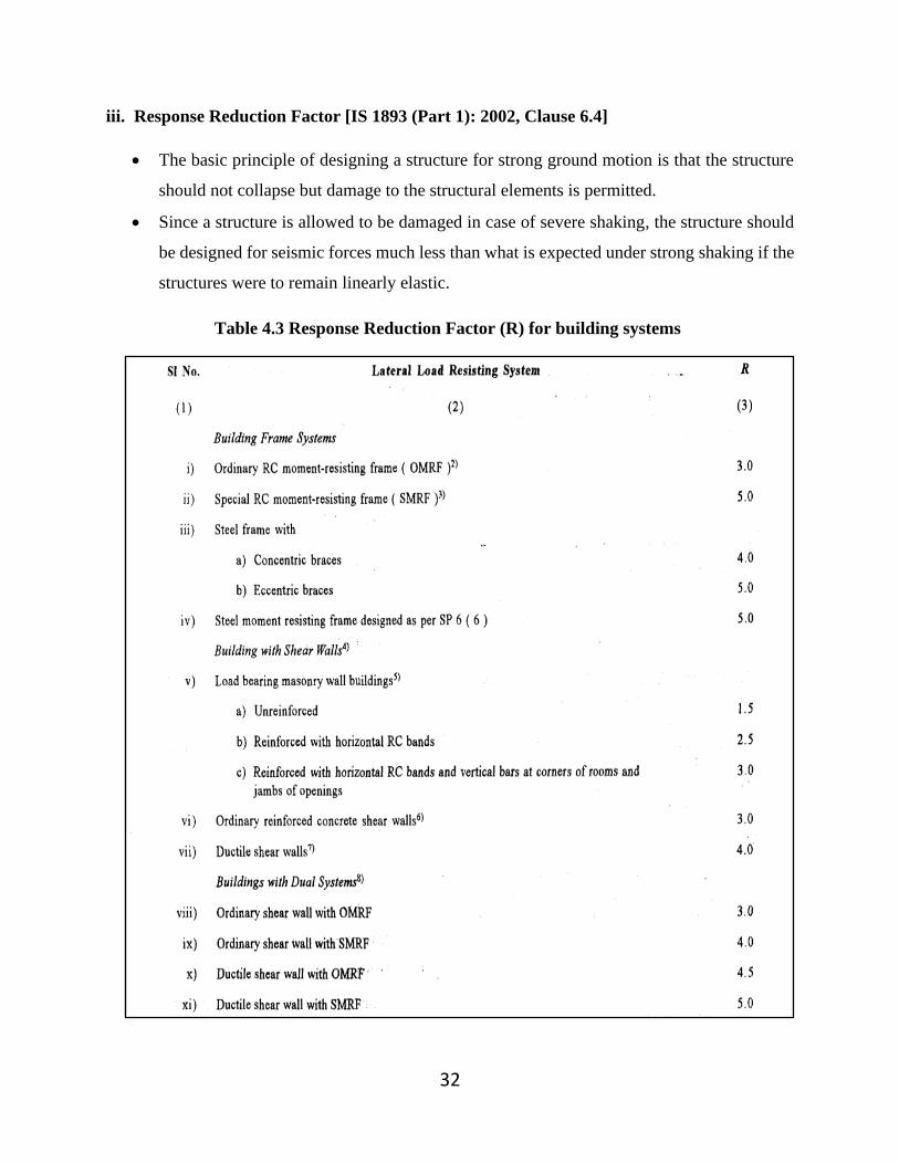
iii. Response Reduction Factor [IS 1893 (Part 1): 2002, Clause 6.4]
• The basic principle of designing a structure for strong ground motion is that the structure
should not collapse but damage to the structural elements is permitted.
• Since a structure is allowed to be damaged in case of severe shaking, the structure should
be designed for seismic forces much less than what is expected under strong shaking if the
structures were to remain linearly elastic.
Table 4.3 Response Reduction Factor (R) for building systems

33
• Response reduction factor (R) is the factor by which the actual base shear force should
be reduced, to obtain the design lateral force.
• Base shear force is the force that would be generated if the structure were to remain elastic
during its response to the design base earthquake (DBE) shaking.
• Table 4.3 gives response reduction factor for building systems.
iv. Fundamental Natural Period [IS 1893 (Part 1): 2002, Clause 7.6]
• The fundamental natural period is the first (longest) modal time period of vibration of
the structure.
• Because the design loading depends on the building period and the period cannot be
calculated until a design has been prepared, IS 1893 (part 1): 2002, Clause 7.6 provides
formulae from which Ta may be calculated.

34
v. Design Response Spectrum [IS 1893 (Part 1): 2002, Clause 6.4.5]
• The design response spectrum is a smooth response spectrum specifying the level of
seismic resistance required for a design.
• Seismic analysis requires that the design spectrum be specified.
• IS 1893 (Part 1): 2002 stipulates a design acceleration spectrum or base shear coefficients
as a function of natural period.
• These coefficients are ordinates of the acceleration spectrum divided by acceleration due
to gravity.
• This relationship works well in SDOF systems.
• The spectral ordinates are used for the computation of inertia forces.
• Fig. 4.2 relates to the proposed 5 percent damping for rocky or hard soils sites and Table
4.4 gives the multiplying factors for obtaining spectral values for various other damping
(note that the multiplication is not to be done for zero period acceleration).
• The design spectrum ordinates are independent of the amounts of damping (multiplication
factor of 1.0) and their variations from one material or one structural solution to another.

35
Table 4.4 Multiplying Factors for Obtaining Values for damping (other than 5%)
4.5. SEISMIC BASE SHEAR [IS 1893 (Part 1): 2002, Clause 7.5.3]
• The total design lateral force or design seismic base shear (VB) along any principal
direction is determined by
VB = AhW …Equation 4.1
Where Ah is the design horizontal acceleration spectrum value using the
fundamental natural period, T, in the considered direction of vibration and W is the
seismic weight of the building.
Fig. 4.2. Response Spectra for rock and soil sites for 5 % damping
36
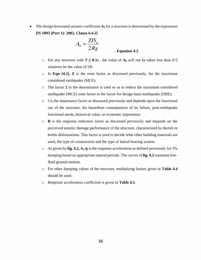
• The design horizontal seismic coefficient Ah for a structure is determined by the expression
[IS 1893 (Part 1): 2002, Clause 6.4.2]
…Equation 4.2
o For any structure with T ≤ 0.1s , the value of Ah will not be taken less than Z/2
whatever be the value of I/R.
o In Eqn (4.2), Z is the zone factor as discussed previously, for the maximum
considered earthquake (MCE).
o The factor 2 in the denominator is used so as to reduce the maximum considered
earthquake (MCE) zone factor to the factor for design basis earthquake (DBE).
o I is the importance factor as discussed previously and depends upon the functional
use of the structure, the hazardous consequences of its failure, post-earthquake
functional needs, historical value, or economic importance.
o R is the response reduction factor as discussed previously and depends on the
perceived seismic damage performance of the structure, characterized by ductile or
brittle deformations. This factor is used to decide what other building materials are
used, the type of construction and the type of lateral bracing system.
o As given by fig. 4.2, Sa /g is the response acceleration as defined previously for 5%
damping based on appropriate natural periods. The curves of fig. 4.2 represent free-
fluid ground motion.
o For other damping values of the structure, multiplying factors given in Table 4.4
should be used.
o Response acceleration coefficient is given in Table 4.5.
37
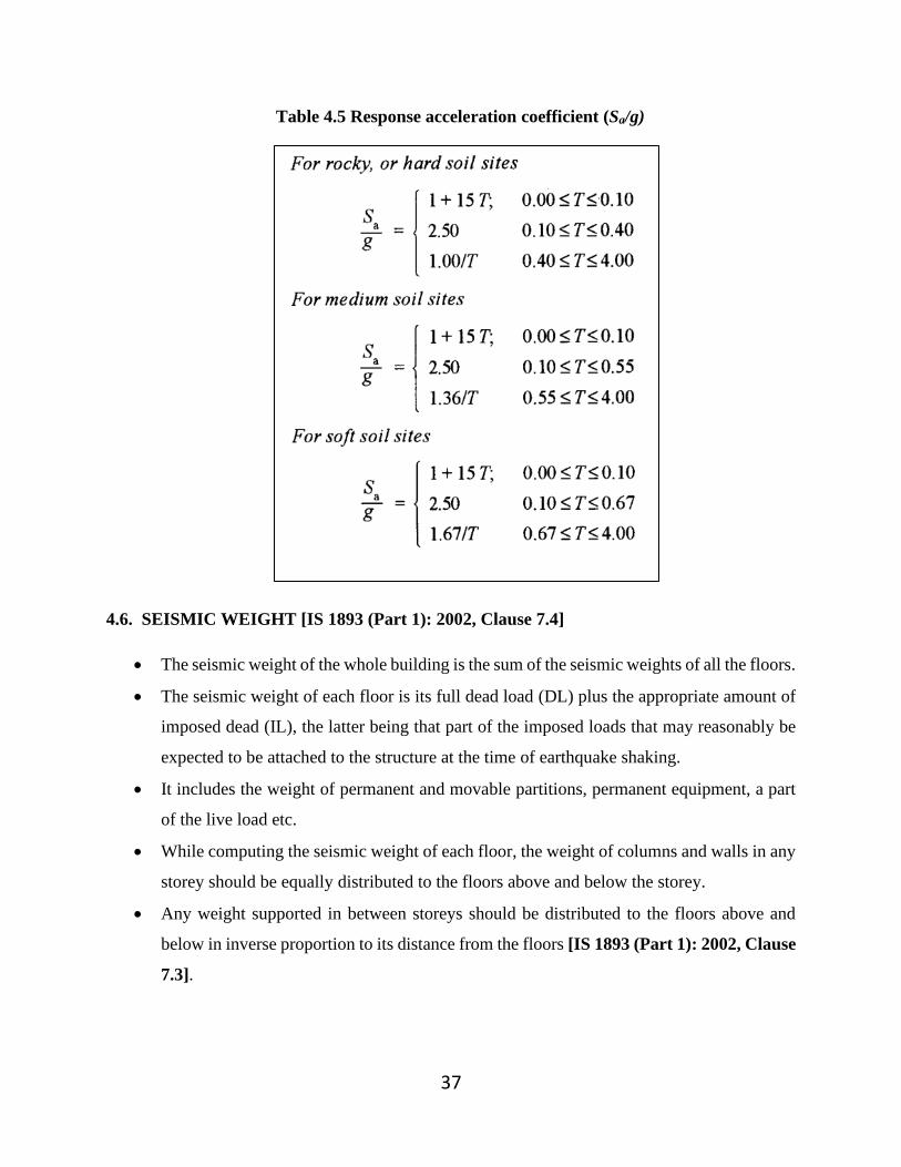
Table 4.5 Response acceleration coefficient (Sa/g)
4.6. SEISMIC WEIGHT [IS 1893 (Part 1): 2002, Clause 7.4]
• The seismic weight of the whole building is the sum of the seismic weights of all the floors.
• The seismic weight of each floor is its full dead load (DL) plus the appropriate amount of
imposed dead (IL), the latter being that part of the imposed loads that may reasonably be
expected to be attached to the structure at the time of earthquake shaking.
• It includes the weight of permanent and movable partitions, permanent equipment, a part
of the live load etc.
• While computing the seismic weight of each floor, the weight of columns and walls in any
storey should be equally distributed to the floors above and below the storey.
• Any weight supported in between storeys should be distributed to the floors above and
below in inverse proportion to its distance from the floors [IS 1893 (Part 1): 2002, Clause
7.3].

38
• As per IS 1893 (Part 1), the percentage of imposed load as given in the Table 4.6 should
be used. For calculating the design seismic forces of the structure, the imposed load on the
roof need not be considered.
• A reduction in IL is recommended for the following reasons.
o All the floors may not be occupied during earthquake
o A part of earthquake energy may get absorbed by non-rigid mountings of IL.
Table 4.6 Percentage of imposed load to be considered in seismic weight calculation
Imposed Uniformly Distributed Floor Loads
(KN/m2)
Percentage of Imposed
Load
Upto and including 3.0 25
Above 3.0 50
4.7. DISTRIBUTION OF DESIGN FORCE [IS 1893 (Part 1): 2002, Clause 7.7]
• Buildings and their elements should be designed and constructed to resist the effects of
design lateral force.
• The design lateral force is first computed for the building as a whole and then distributed
to the various floor levels.
• The overall design seismic force thus obtained at each floor level is then distributed to
individual lateral load resisting elements depending on the floor diaphragm action.
4.7.1 Seismic Coefficient Method
• This is also known as equivalent lateral force method or equivalent static method or
static method.
• This method is the simplest one - it requires less computational effort and is based on
formulae given in the code of practice.
• First, the design base shear is computed for the whole building and it is then distributed
along the height of the building. The lateral forces at each floor level thus obtained are
distributed to individual lateral load resisting elements.

39
• Vertical distribution of base shear to different floor levels [IS 1893 (Part 1): 2002,
Clause 7.7.1]
o The design base shear (VB) is distributed along the height of the building as per the
following expression.
Where Qi is the design lateral force at floor i, Wi is the seismic weight of
the floor i, hi is the height of floor i measured from the base, and n is the
number of storeys in the building i.e, the number of levels at which the
masses are located.
• Distribution of horizontal design lateral force to different lateral force resisting
elements [IS 1893 (Part 1): 2002, Clause 7.7.2]
o In the case of buildings in which floors are capable of providing rigid horizontal
diaphragm action, the total shear in any horizontal plane is distributed to the various
vertical elements of the lateral force-resisting system, assuming the floors to be
infinitely rigid in the horizontal plane.
o For buildings in which floor diaphragms cannot be treated as infinitely rigid in their
own plane, the lateral shear at each floor is distributed to the vertical elements
resisting the lateral forces, accounting for the in-plane flexibility of the diaphragms.

40
4.8 PROBLEMS
PROBLEM 4.1
PROBLEM 4.2

41

42
43
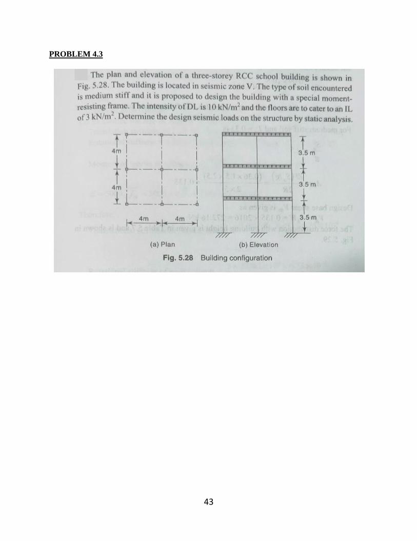
PROBLEM 4.3

44

45

46
PROBLEM 4.4

47

48

49
PRACTICE QUESTION

50
LECTURE – 5 SIGNIFICANCE OF DUCTILITY
DUCTILITY OF BEAM
DESIGN AND DETAILING FOR DUCTILITY
SIMPLE PROBLEMS BASED ON ABOVE CONCEPT AS PER IS 13920

21.3 SIGNIFICANCE OF DUCTILITY
When a ductile structure is subjected to overloading it will tend to delorm inelastically and in doing so, will redistribute the excess load to elastic parts of the structure. This
concept can be utilized in several ways
)It a stnucture is ductile, it can be expected to adapt to unexpected overloads, load reversals, inmpact and structural movements due to foundation settlement and volume changes. These items are generally ignored in the analysis and design but are assumed
to have becn taken care of by the presence of some ductility in the structure.
(2) If a structure is ductile. its occupants will have sufficient warning ol the impending
failure thus reducing tlie probability of loss of life in the event of collapse.
3) The limit state design procedure assumes that all the critical sections in the
For structure
this to will reach their maximum capacities at design load for the structure.
occur, all joints and splices must be able to withstand 1orces and deformatione
coresponding to yielding of the reinforcement.
Ductility Member or structural ductility is defined as the ratio of absolute maximum
deformation to the corresponding yield deformation. meaning until the method of measuring the deformation has been defined. This can he
defined with respect to strains, rotations, curvatures or deflections. Strain based ductility
definition depends almost exclusively on the material, while rotation or curvature based
ductility definition also includes the effects of shape and size of the cross-section. When the definition is applied to deflections, the entire configuration of structure and loading is
also taken into account.
However, ductility has no precise
It should be noted that no definition claims any special merit
over the others.
In the typical force-deformation relation plotted in Fig. 21.1, the force may be load,
moment or stress, while the deformation could be elongation, curvature, rotation or
strain. Ay is the yield de formation corresponding to yielding of the reinforcement in a
cross-section or to a major deviation from the linear force-deformation curve for a
member or structure. Au is the ultimate deformation beyond which the force-deformation
curve has a negative slope. The ductility u is defined by the equation:
with respect to displacement y
(21.la)
with respect to curvature y
(21.1b)
with respect to rotation y (21.lc)
Ductility requirements The assignment of structural ductility factor to a structure has to be consistent with the
capability of the associated detailing of reinforcement as well as material strains within the structure. It v Juld depend upon:
(a) Plastic hinge mechanisms that may develop within the structure, (b) Material strain demands within the inelastic zones,

Material strain capabilities, and
(d) Ine (Caelastic displacemnent profile of the structure, usually base shear - roof displacement plot.
14 DUCTLITY OF BEAM
of reinforced concrete beams may be defined in terms of the behaviour o The
ductility of "rOSS-scction or the behaviour of entire beanm. The former definition is more widely ndiv ndue the behaviour of cross-section is much better defincd and it is easier to compute.sed
because
the i
Let derive cxpression tor the curvature ductility of a beam. With reference to Fig. ield curvature of a singly reinforced beam can be computed using the elastic
21.Sa, the
theory, that is,
y Ey d- Nd (21.2a)
where
Ey vield strain of the tensile reinforcement = oy/Es cffective depth
depth of neutral axis computed using elastic theory
d
Nd
N mp + mp* + 2mp
(21.2b) modular ratio 280/3 Gcbe
tension steel ratio = A/bd P
&u
Nd
X d u
Ey
&ym SECTION STRAIN STRAIN
Fig. 21.5a Yield curvature Fig. 21.5b Ultimate curvature
Similarly with reference to Fig. 21.5b, the ultimate curvature can be computed as,
u (21.2c) X
where, Ey = ultimate strain at crushing of concrete = 0.0035
0.87oyA 0.36kb
0.87o, pd X (21.2d)
0.360ck
Xm

Substituting Eqs. 21.2a and 21.2c in Eq. 21.1b gives,
d - Nd
(21.3a)
1+ mp ym'p*+ 2mp u (21.3b) x/d of
y/Es
derived. The addition of compression reinforcement to a beam has relatively little er
on its yield curvature. It does, however, greatly increase the ultimate curvature. TL
depth of neutral axis at collapse can be determined from the expression
In the case of a doubly reinforced beam, a similar expression for ductility factor Can effect be
The
0.36 ock bx + oy Ase = 0.87 ay At
y 6 0.87p (21.4a) e0.360ck y of
where, oy stress in the compression reinforcement
Pc Asc/bd
If oy = 0.87 oy
0.87 y (p-Pc 0.36 Ock
Eq. 21.4a becomes
(21.4b)
Xm
ng. 21.5 also gives &ym d - x
u (21.4c) E+Eym or,
Eu+ym
where, Eym maximum strain in tensile steel = Hs Eu
Hs strain ductility in steel
Eq. 21.4b can be rewritten as
E Eu 0.360ek (P-P +Hy 0.870, (21.4d)
Thus ductility can be obtained by using either Eqs. 21.3b and 21.4b, or Eqs. 21.3a and 21.4c. Values of calculated using Eq. 21.3b and Eq. 21.4b are presented in Fig. 21.6 for Fe 415 grade steel.

ables affecting the ductility ariables
Tension steel ratio p
As shown in Fig am in Fig. 21.6 the ductility of a beam cross-section increases as the steel ia D.) decreases. excessive reinforcement is provided, the concrete il crusi p or the steel of stcel yields, leading to a brittle failure corresponding to 1.0. In other hefore
a beam should be designed as under reinforced. words
10
6
5
L L 0 0.004 0.008 0.012 0.016 0.020 0.024 0.028 0.032
TENSION STEEL RATIO p OR p-P Fig. 21.6 Curvature ductility in beams with Fe 415 steel
The ductility is directly affected by the values Eu, Ock and oy. The ultimate strain Eu is
function of a number of variables such as the characteristic strength of concrete, rate of
loading and strengthening effect of stirrups. The Code recommends a value of 0.0035 for It can be seen in Fig. 21.6 that ductility increases with the increase in characteristic
strength of concrete. Eq. 21.3 shows that ductility decreases with the increase in characteristic strength of steel. In tact, ductility is inversely proportional to the square of
oy. It suggests that Fe 415 grade steel is more desirable from the ductility point of view as compared with Fe 500 grade high strength steel.
(2) Compression steel ratio p
Eq. 21.4b suggests that (p - Pc) is an important parameter defining the ductility ratio.
Figure 21.6 shows that ductility increases with the decrease in (p - pc) value, that is,
ductility increases with the increase in compression steel.
(3) Shape of cross-section
The presence of an enlarged compression flange in a T-beam reduces the depth of the compression zone at colapse and thus increases the di.ctility. If neutral axis falls in the flange, then ductility can be calculated using Fig. 21.6.
(4) Lateral reinforcement
Lateral reinforcement tends to improve ductility by preventing premature shear failures, restraining the compression reinforcement against buckling and by confining the compression zone, thus increasing deformatidn capability of a reinforced concrete beam.
21.5 DESIGN FOR DUCTILITY
Selection of cross-sections that will have adequate strength is rather easy. But it is

much more difficult to achieve the desired strength as well as ductility. Suticient ductility, the designer should pay attention to detailing of reinlorcement, bar
cut-offs, splicing and joint details. following certain simple design details such as
To nsure
Sufficient amount of ductility can be ensured by
(1) The stnictural layout should be simple and regular avoiding offsets of beams to
columns, or offsets of columns from floor to floor. Changes in stiffness should be
gradual from floor to floor. (2The amount of tensile reinforcement in beams should be restricted and more
compression reinforcement should be provided. The latter should be enclosed by
stirnups to prevent it from buckling. ) Beanms and columns in a reinforced concrete frame should be designed in such a
manner that inclasticity is confined to beams only and the columns should remain
elastic. To ensure this, sum of the moment capacities of the columns for the
design axial loads at a beam-column joint should be greater than the moment
capacities of the beams along each principal plane.
(21.5) XMcolumn > 1.2 2Mbeam
The flexural resistances be summed such that the column moments oppose the
beam moments as shown in Fig. 21.7.
Mc1
Mb2 Mb1
Mc2
Fig. 21.7 Weak girder-strong column requirement
(4) The shear reinforcement should be adequate to ensure that the strength in shear exceeds the strength in flexure and thus, prevent a non-ductile shear failure before
the fully reversible flexural strength of a member has been developed.
Clause 6.3.3 of IS: 13920-1993 requires that the shear resistance shall be the maximum of the:
(a) Calculated factored shear force as per analysis, and
(b) shear force due to formation of plastic hinges at both ends plus the factored gravity loads on the span.
i) For sway to right (Fig. 21.8)
MAS +M Va 1.4 +0.5wLc Le

0.5wle (21.6a) Le
For sway to left
(1)
v-1.4 M" M" - 0.5wlc
Vb 1 MhM +0.5wlc (21.6b) Le
where
Mu hogging or sagging moment capacity at the left end of the beam 1.4 times the yield mnoment capcity at each end of the beam
Mu Assagging moment capacity at the left end of the beam
M ,bh hogging moment capacity at the right end of the beam
factored gravity load = 1.2 (DL + LL)
clear span of beam Le
Mu,Ah W Mu,Bs
SEISMIC LOADING
Mu,As W Mu.Bh
iiiii
REVERSE SEISMIC LOADING
Fig. 21.8 Reversal of shear due to seismic loading
The resistance Mp corresponds to the moment of resistance of the beam section on
either side of the joint. It is assumed that the ratio of the actual ultimate tensile stress to
the actual tensile yield strength of the steel is not less than 1.25. Use of longitudinal
reinforcement with yield strength substantially higher than that assumed in the design will
lead to higher shear and bond stresses at the time of development of yield moment. This
may lead to unexpected brittle failures and should be avoided. It is known that the length
of the yield region is related to the relative magnitudes of the ultimate and yield strengths.
The larger is the ratio of the ultimate to yield moment, the longer is the yield region. The
factor 1.4 is equal to 1.25 times the yield strength of steel divided by 0.87 (that is
1.25/0.87 1.43 1.40).
The design shear at each end A and B shall be the absolute maximum of the
coTesponding two values of Va and Vp.

) The des1gn shear force for columns will be the maximum ot (a) Calculated factored shear force, and (b) A factored shear force given by
V14 M Mh he
(21 6c)
(0) Closed stimups or spirals should be used to confine the concrete at sections of maximum moment to increase the ductility of members. Such sections include
upper and lower ends of columns, and within beam-column joints which do have beams on all sides. If axial load exceeds 0.4 times the balanced axial load,a
spiral colunmn is preferred.
not
)Splices and bar anchorages must be adequate to prevent bond failures.
(8) The reversal of stresses in beams and columns due to reversal of direction .e
earthquake force must be taken into account in the design by provIding appropriate
reinforcement.
(9) Beam-column connections should be made monolithic.
21.6 DETAILING FOR DUCTILITY
The following recommendations are based on the provisions of IS: 4326-1993. Is. 13920-1993 and ACI 318-2008 and lessons learnt from the falure of concrete structures
during past earthquakes. (4) Girders
A girder should satisfy the following requirements: (1) The factored axial stress on these members under earthquake loading should not
exceed 0. 1ock.
1ot
(2) The width to depth ratio of the member is more than 0.3.
(3) The depth of the member is not more than 1/4th of the clear span.
Longitudinal Reinforcement
(1) At any section of a flexural member and for the top as well as for the bottom
reinforcement:
(i) the reinforcement ratio p should each be greater than
IS: 13920-1993 p >0.24/k (21.7a)
Oy
0.25/ck hut not less than p y
(21.7b) ACI 318-2008 P>
where
o'ck cylinder strength of concrete
for rectangular sections bd P
As for flanged sections bd

As area of stcel on either face
the reinforcement ratio p should not exceed 0.025.
(2) At least two At least two bars should be provided continuously both at top and bottom.
one
The positive moment resistance at the face of a joint should not be less than
(nc- half of the negative moment resistance provided at that face of the Joint. nesign Tables 21.2 and 21.3 similar to Tables 5.4 and 6.2 have becen generated 1ISing the above recommendations and may be used for the design of beam sections tor ductility.
Table 21.2 Tension and compression steel pr and pe for M30 conerete and Fe 500 grade steel (p/pe $2.0) dd-0.05 d/d 0.10 d,/d-0.15 M bd d/d 0.20
P 0.237
P 0.119
P 0.000
P 0.000
P 0.000
P 0.000
P 0.000
P 0.000 1.00
0.286 0.143 120 40
0.000 0.000 0.000 0.000 0.000 0.000 1 0.335 0.167 0.000 0.000 0.000 0.000 0.000 0.000 1.60 0.385
0.434 0.193 0.217
0.000 0.000 0.000 0.000 0.000 0.000 80 0.444 0.222 0.000 0.000 0.000 0.000
2.00 0.484 0.242 0.494 0.247 0.000 0.000 0.000 0.000 2.20 0.534 0.267 0.546 0.273 0.000 0.000 0.000 0.000
. 584 0.292 0.598 0.299 0.611
0.325 0.665 0.332 0.3510.718 0.359
0.772 0.827
0.431 0.882 0.938
2.40 0.306 0.000 0.000 0.633 0.3 16 0.650 2.60
2.80 0.684 0.735
0.000 0.000 0.342 0.702 0.000 0.000
3.00 0.367 0.756 0.378 0.386 0.000 0.000 0.786 0.837
3.20 0.393 0.809 0.405 0.414 0.847 0.423 3.40 0.418 0.862 0.441 0.904 0.452
0.480 0.915 0.457 0.969
0.495 1.022
3.60 0.888 0.444 .469 0.960 0.497 1.017 0.509
1.076 1.136 0.568
3.80 4.00
0.939 0.470 0.484 0.511
1.076 0.538
0.995 0.991 1.051 0.526
1.1080.554 0.538
4.20 1.044
4.40 1.095 0.548 1.130 1.150
0.522
0.565 1.165 0.583 I.194 0.612 1.255 0.640
0.597 4.60 0.575 1.186 0.593 1.224
0.620 1.281 1.338 1.396
0.627 0.657 0.688
4 80 1.202 0.601 1.240 1.315 1.256
5.20 1.309
5.40 1.363 0.682
5.60 1.417 0.709 1.472
6.00 1.526 0.763 1.582
6.40 1.639 1.693
1.749 . 808
0.628 1.297 1.352
1.409
S.00 0.648 0.669 1.376 0.654 0.676 0.698 1.438 0.719
0.704 1.455 0.728 .501 0.751 1.466 0.733 1.515 0.757 1.563 0.782
1.522 1.580
5.80 0.736 0.761 0.790 0.818
1.573 0.786 T.628 0.814
0.816 1.6910.846 0.876
1.817 0.908 0.940
0.937 1.944 0.972
0.969 2.002 1.042 1.111
2.116 1.181
633
1.693 0.846 1.753 0.876
0.907
6.20 0.791 1.637 0.819 1.694
0.847 1.753 0.875 1.812
0.847 0.876 0.906
1.871 0.935 1.930 0.965
1.753 6.60 1.813 1.881 6.80 1.875 7.00 0.904 1.937 7.20 0.932 2.000
2.059
1.864 1.000 1.042
2.058 7.40 1.920 0.960 1.989 0.995
7.60 1.979 0.989 2.050 1.025 2.113 1.104 2.174 1.251
1.166 2.231 .321 1.227 2.288 1390
2.037 1.019 2.110 1.056 7.80 8.00 2.095 1.048 2.162 1.112 2.221
2.168

Table 21.3 Tension and compression steel p and Pe
for M35 concrete and Fe 500 grade steel (pi/pe S 2.0)
d,/d- 0.05 d,/d 0.10 d,/d 0 15 d,/d-0.20 M/bd P
0.000 P PL P
0.000 P P Pe 0.238 0119 0.000
0.143 0.000 0.167
P 0.000 1.00 0.000 0.000
0.000 0.000 0.000 0 000 1.20 0.286 0 000
0.000 0.000 0.000 140 0335 0.000 0.000 0.000
0.000 0.000 0.000 I.60 0.384 0.192 0.000 0.000 0.000
0.000 0.000 0.000 80 0.432 0.216 0.000 0.000 0.000
0.000 0.000
0.000 0.000
0.000 0.000
0.000 0.000 0.4810.241 0.266
2.00 0.492 0.246 0.000
0.542 0.271 0.297
0.000 2.20 0.532 0.000 0.000 0.000
2.40 0.580 0.290 0.594 0.000 0.000
0.000 2.60 0.629 0.315 0.646 0.323 0.000
0.000 0.340 0.697 0.349 0.712 0.356
2.80 0.681 0.383 0.000 0.000 0.765 0.365 0.749
0.801
0.854
3.00 0.730 0.375 0.819 0.409 0.000 0.000 0.4011
0.427 3.20 0.781 0.390
0.416 0.874 0.437 0.000 0.000 3.40 0.831 0.950 0.475 0.464
0.984 0.492 1.007 0.519
.60 0.882 0.441 0.908 0.454 0.929
0.503 .80 0.933 0.467 0.960 0.480
1.063 0.532
0.560 0.589 0.618
0.984 0.492 1.015 0.507 1.039 4. 00 0.5471.120
1.151 0.575 1.178 0.604 1.236
0.632 1.295
0.661 0.689 1.414
4.20 1.037 0.518 1.068 0.534 1.094 0.544 1.121 0.561
1.175 4.40 1.088 4.6 1.139 0.569 0.587 1.207 4.80 1.192 0.596 1.230 0.615 1.264 0.647
0.677 0.707
1.354 1.322 1.337 0.669 1.379
0.696 1.437
0.724 1494 1.553
0.642 5.00 1.245 0.622 1.297 0.649 1.350 0.675
1.283
5.20 5.40 5.60
0.719 1.474 0.737 1.393 1.448 0.747
0.777 1.534 1.596
0.767 0.798
1.404 0.702
5.80 1.456 6.00 1.510
6.20 1.564 1.618
0.728 1.503 0.751 0.755 1.559 0.780 1.610 0.782 1.616 0.808 1.669
1.673
1.657 1.720 0.860 1.783 0.892 1.846
0.805 0.829
0.834 I.728
0.865 1.787 0.894
0.893 1.847 0.923 1.907
1.966 | 0.983
2.026 2.088
40 0.809 0.836 0.864
6.60 1.672 0.8361.729 0.923
1.7280.864 1.782 1.838
7.40 1.894 0.947 1.958 1.950
7.80 2.006
1.786 1.843 0.921
1.901
6.80 1.910 0.955 0.986 7.00 0.891 0.953 1.973
7.20 0.919 0.951 2.036 1.018 1.049 0.979 1.013 2.098
1.008 1.038
7.60 0.975 2.017 1.044 2.162 1.081 2.226 1.113 2.287 1.166
1.003 2.076 2.148 1.074
8.00 2.063 1.031| 2.135 1.067 2.209 1.105
(4) Neither the negative nor the positive moment resistance at any section along the member length should be less than one-fourth of the maximum moment resistance provided at the face of either joint.
(5) The detailing rules as discussed in Chapter 9 are adequate and should be carefully followed.
(6) When a beam frames into a column, both the top and bottom bars of the beam should be anchored into the column so as to develop their full strength in bond beyond the section of the beam at the face of the column. Where beams exist on

hoth sides of the column, both face bars of beams must be taken continuously
through the column as shown in Fig. 219. To avoid congestion of steel in a column
n which the beam frames on one side only, the use of hair pin type of bars spliced
ifside the column instead of anchoring the bars in the column is suggested. EXTREME LOCATION OF POINTS OF INFLECTION
GREATEROF d, 12 OR U16 La
Ld
La
Fig. 21.9 Detailing of main reinforcing bars in beams
Shear Remforcemen
(7 The design of shear stirrups follow normal practice as discussed in Chapter 8.
The spacing of the vertical stirrups should not exceed 0.25 d in a length equal to
2d near each end of the beam and 0.5 d in the remaining length of the beam as shown in Fig. 21.10.
ADD:TIONAL STIRRUPS AT
= 0.25d CUT OFFS = 0.25d
2d - 2d
JOINT HOOPS = 0.5d IN
REMAINING LENGTH
Fig. 21.10 Detailing of shear stirrups
B) Columns
A column should satisfy the following requirements:
(1) The factored axial stress P/A on a column under earthquake condition is more
than 0.1 ock
(2) The ratio of shortest cross-sectional dimension to the perpendicular dimension is not less than 0.4.
(3) The minimum dimension of the member is 200 mm. However, in frames where the beam span exceeds 5 m c/c, or the columns having unsupported length exceeds 4 m, the shortest dimension of a column should not be less than 300 mm.
Special Confining Reinforcement (1) IF P/A 20.1 Gck, special confining reinforcement is required at the column ends
() The cross-sectional area of bars forming circular hoops or spirals used for
confinement of concrete is given by:

ck 0.09 S D -1 k (218) cAc asp
(1i) Clause 7.4.7 of IS. 13920 gives two equations to detemine area of one le
the special confinement reinforcement in a column or wall section. A CrO
of may be provided in order to reduce the valuc of spacing 'h'. In the e
by:
This is the same as Eq. 16.7d.
rectangular closed stirmups used in rectangular sections, the arca of ties is give
(21.9) 0.18 ShE - Gck o.18 SAc asp
The maximum value of 'h' is 300 mm. However, a cross-tie must enos
peripheral longitudinal bars. The above cquation was adopted from the then Ac
318 code. This equation has been revised. Clause 21.6.4.4 of the ACI 318-200
provides a set of two cquations to compute total area of transverse reinforcemer
per unit height rather than the area of one leg only. These equations are
independent of 'h' but its value is restricted to 350 mm. The detailing of tiec i
wn in Fig. 21.11. It should be noted that consecutive cross ties engaging the
same longitudinal bar have their 90° hooks on opposite sides of the column.
where h= longer dimension of the rectangular confining stirrup
6db EXTENSION
Ash2 - 6db 75 mm
X1
Bc2
X1
Ash1-
X1 X1 X1
Bc1
Fig. 21.11 Detailing of lateral ties in a column
A-10 fyAch (21.10a) Ash 0.3 Sb
Ash 0.09 Sb (21.106)
where
bc Cross sectional dimension of member core measured to the outside edges of transverse reintorcement
Longer dimension of the rectangular confining hoop measured to its outer

fk.fe Characteristic compressive strength of concrete cube, Yicld stress of steel used in hoops fy Spacing of hoops
Equations 21.10a and 21.10b are to be satisfied in both cross sectional directions of the rectangular core. For cach direction, be is the core dimension perpendicular to the tie legs that constitute Ash The special confining steel where required must be provided above and below the hcam connections as shown in Fig. 21.12, in a length of the column at each end which is largest of the following:
50 GREATER OF /6,b OR 450 mm
USUAL TIES
LOCATE SPLICES NEAR MID HEIGHT BUT NOT CLOSER THAN 'b' TO JOINT
GREATER OF /6,b OR 450 mm
50
Fig. 21.12 Spacing of lateral ties
(i) 1/6 of the clear height of the column, (ii) larger lateral dimension of the column, and (iii) 450 mm.
The pitch of lateral ties should not exceed 1/4th of the minimum member
dimension
nor
100
mm.
(3) When the calculated point of contra-flexure under the effect of gravity and earthquake loads is not within the middle half of the member clear height, special confinement reinforcement must be provided over the full height of the column. Clause 5.4.3.2 of Eurocode 1998-1 requires that if le/he< 3, the entire height of the primary seismic column shall be considered as being a critical region and shall be reinforced accordingly,
where
hthe largest cross-sectional dimension of the column (in metres) clthe clear length of the column (in metres)
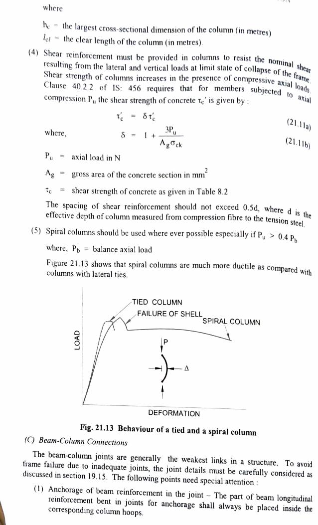
shear (4) Shear reinforcement must be provided in columns to resIst the nominal resulting from the lateral and vertical loads at limit state of collapse of the a
ssive axial of the fra Shear strength of columns increases in the presence of compressive axial Clause 40.2.2 of IS: 456 requires that for members subjected to,
compression P, the shear strength of concrete Te' is given by :
(21.1la) 3Pu (21.11b)
where, =I4+
Pu axial load in N 2 Ag gross area of the concrete section in mm
Te shear strength of concrete as given in Table 8.2 Tc
The spacing of shear reinforcement should not exceed 0.5d, where d i effective depth of column measured from compression fibre to the tension steel the
(5) Spiral columns should be used where ever possible especially if Pu > 0.4 P where, Pb = balance axial load
Figure 21.13 shows that spiral columns are much more ductile as compared with columns with lateral ties.
TIED COLUMN
FAILURE OF SHELL SPIRAL COLUMN
P -A
DEFORMATION
Fig. 21.13 Behaviour of a tied and a spiral column C) Beam-Column Connections
The beam-column joints are generally the weakest links in a structure. To avoid frame failure due to inadequate joints, the joint details must be care fully considered as discussed in section 19.15. The following points need special attention (1) Anchorage of beam reinforcement in the joint The part of beam longitudinal reinforcement bent in joints for anchorage shall always be placed inside the corresponding column hoops.
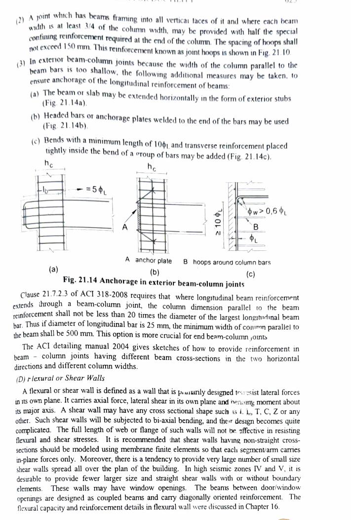
A 1oit which has beams framing into all verticau laces of it and where cach beam
wdth is at lcast S4 ot the cohumm width, may be provided with half the specia confining reinforcenent required at the end of the column. The spacing of hoops shal not exceed S0 mm This reinforcement known as joint hoops is shown in Fig. 21.10
In exterior beam-column joints because the width of the column parallel to the heam bars is too shallow, the following additional measures may be taken, to
ensure anchorage ot the longitudinal reinforcement of beams: (a) The beam or slab may be extended horizontally in the form of exterior stubs (Fig. 21.14a).
not
(b) Headcd bars or anchorage plates welded to the end of the bars may be used (Fig. 21.14b).
(c) Bends with a minimum length of 1001 and transverse reinforcement placed tightly inside the bend of a oroup of bars may be added (Fig. 21.14c). hc
5
w 0,6 B
A anchor plate B hoops around column bars
(a) (b) Fig. 21.14 Anchorage in exterior beam-column joints
(c)
Clause 21.7.2.3 of ACI 318-2008 requires that where longitudinal beam reinforcement
extends through a beam-column joint, the column dimension parallel to the beam
reinforcement shall not be less than 20 times the diameter of the largest longitidinal beam har. Thus if diameter of longitudinal bar is 25 mm, the minimum width of coimn parallel to
the beam shall be 500 mm. This option is more crucial for end beam-column ,ounts The ACI detailing manual 2004 gives sketches of how to orovide reinforcement in
beam column joints having different beam cross-sections in the two horizontal directions and different column widths.
(D) rlerural or Shear Walls
A flexural or shear wall is defined as a wall that is puuiarily designed toiesist lateral forces in Its own plane. It carries axial force, lateral shear in its own plane and inenomy moment about its major axis. A shear wall may have any cross sectional shape such i i. L, T. C, Z or any other. Such shear walls will be subjected to bi-axial bending, and the r design becomes quite complicated The full length of web or flange of such walls will not be sffective in resisting
It is recommended that shear walls havng non-straight cross sections should be modeled using membrane finite elements so that eacl1 segment/arm caries in-plane forces only. Moreover, here is a tendency to provide very large number of small size shear walls spread all over the plan of the building. In high seismic zones IV and V, it is desitrable to provide fewer larger size and straight shear walls with or without boundary
The beans between door/window
flexural and shear stresses.
elements. These walls may have window openings. openings are designed as coupled beams and carry diagonally oriented reinforcement. The
flexural capacity and reinforcement details in flexural wall were discussed in Chapter 16.
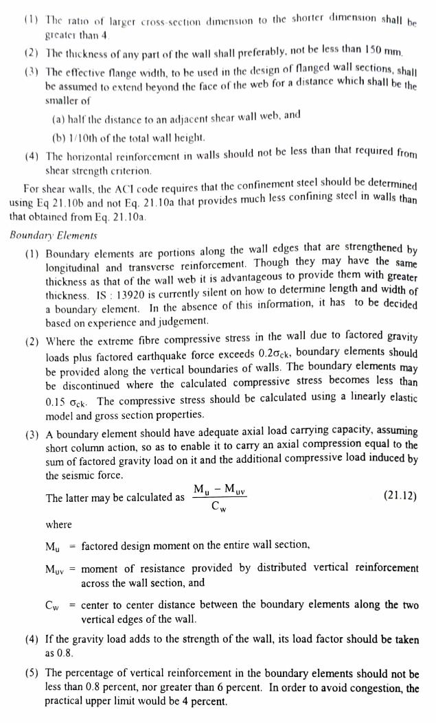
The atio of larger cross-section dimension to the shorter dimension shalI he
greatcr than 4 2)The thickness of any part of the wall shall preferably, not be less than 150 mm
(39 The eftfective Mange width, to be used in the design of langed wall sections, shal be assumed to extend beyond the face of the web for a distance which shall be the
smaller of
(a) half the distance to an adjacent shear wall web, and
(b) 1/10th of the total wall height. (4) The horizontal reinforcement in walls should not be less than that required from
shear strength criterion.
For shear walls, the ACI code requires that the confinement steel should be determined
using Eq 21.10b and not Eq. 21.10a that provides much less confining steel in walls than
that obtained from Eq. 21.10a.
Boundary Elements
(1) Boundary elements are portions along the wall edges that are strengthened by
longitudinal and transverse reinforcement. Though they may have the same thickness as that of the wall web it is advantageous to provide them with greater
thickness. IS: 13920 is currently silent on how to determine length and width of
a boundary element. In the absence of this information, it has to be decided
based on experience and judgement.
(2) Where the extreme fibre compressive stress in the wall due to factored gravity
loads plus factored carthquake force exceeds 0.2Gck, boundary elements should
be provided along the vertical boundaries of walls. The boundary elements may be discontinued where the calculated compressive stress becomes less than
0.15 Ock. The compressive stress should be calculated using a linearly clastic
model and gross section properties.
(3) A boundary element should have adequate axial load carrying capacity, assuming
short column action, so as to enable it to carry an axial compression equal to the sum of factored gravity load on it and the additional compressive load induced by
the seismic force. M, - Mu
The latter may be calculated as (21.12) Cw
where
My factored design moment on the entire wall section,
Myy = moment of resistance provided by distributed vertical reinforcement
across the wall section, and
Cw center to center distance between the boundary elements along the two Cw vertical edges of the wall.
(4) If the gravity load adds to the strength of the wall, its load factor should be taken as 0.8.
(5) The percentage of vertical reinforeement in the boundary elements should not be less than 0.8 percent, nor greater than 6 percent. In order to avoid congestion, the
practical upper limit would be 4 percent.

(6) Boundary elements, where required, should be provided throughout their height with special confining reinforcement as per Eq. 21.9.
(7) Roundary clements need not be provided, if the entire wall section is provided
with special confining reinforcement as per Eq. 21.9.
For a bour boundary clement, clause 21.9.6.2 of ACI 318 specifies how to determine the
depth of neufral axis Nd:
Nd
600(6,/h) (21.13)
where, design displacement, 7= length of shear wall
e a given factored axial force, moment capacity is determined using appropriate curve for a column, that is, boundary element. Thus depth Nd is interaction
calculat.
Pated for the factored axial force and moment capacity consistent with the design The ratio S,/h should not be taken less than 0.007. This helps displacement &.
detemin length of boundary element.
The he thickness of the boundary element can be determined as per clause 5.4.3.4 of EC
s-Part 1 as follows:
If 2t and 0.2 w. tb > h/10
If b < 2tb and 0.2 /w. tb > h/15
where storey height or height of shear wall
h = length of boundary element
thickness of boundary element.
h
The design of foundation of a shear wall needs more attention as it may be under uplift
due to large bending moment at its base.
1.7 ILLUSTRATIVE EXAMPLES
Example 21.1
ARC. frame consists of beams having spans of 6 m c'c. A typical floor inner beam caries a negative bending moment of 450 kNm and a shear of 325 kN at the face of beam
column joint due to gravity and earthquake loads. Design the beam section for ductility.
Solution Let the cross section of beam = 350 x 650 mm
Effective cover for tension steel = 75 mm
Factored bending moment = 450 x 1.2 = 540 kNm
Mu bd
540 x 10 = 4.67 350x 575
The section can be designed as a doubly reinforced section. For M20 concrete and Fe 415 D grade steel, (d'/d = 0.075) or d' 40 mm
where d'= effective cover for compression steel
Tension steel p =1.53 % and

Compression steel pe 0.60 %
0.24 o 0.24 20 415
Minimum tension steel Pmin y
0.00259 or, 0.26 % OK
Maximum tension steel pmax.2.5 %> 1.53 % OK
However, the positive moment capacity is less than 50% of the negative mor
capacity at the same face. Thus, it violates the ductility provisions of IS: 13920-1901 Let us redesign the section as a doubly reinforced section such that the compression steel
is at least 50 % of the tension steel at this section.
moment
d''d 0.075,
P 148 % = 29.87 cm
and Pe 9.74 % = 14.89 cm
Provide 5-28 bars at the top face (A = 30.78 cm) and 3 28 o bars at the botto
face (Ase = 18.47 cm).
Shear force Factored shear force V 1.2 x 325 390 kN
Shear strength of concrete for 1.48 % tension steel,
Te 0.72 MPa
390 x 1000 Nominal shear stress Ty
bd 350 x 575
=1.94 MPa< 2.8 MPa OK
Let us choose 8 ¢ -4 legged stirups. The spacing of stirrups is given by
0.8/oyAsy X (Ty T b
0.87 x 415 x 4x 50 = 169 mm
x (1.94 0.72) x 350
= 143.75 mm
8x 28 o = 224 mm
100 mm
Let us provide 8 mm 4 legged stirrups @ 125 mm c/c in a length equal to
2 d 1150 mm from the face of the beam column joint. The reinforcement detail is shown
in Fig. 21.15. The first stirrup can be provided at a distance of 25 mm from the face of the Joint so that the remaining spacing is 1125 mm. It will require a total of 10 stirrups.
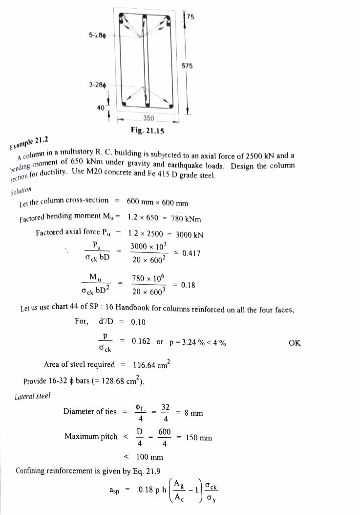
75 6-8
575
3-28
40
350
Fig. 21.15 Example 21.2
in a multistory R. C. building is subjected to an axial force of 2500 kN anda bending moment
for ductility. Use
A column in a mul
noment of 650 kNm under gravity and earthquake loads. Design the column
ductility. Use M20 concrete and Fe 415 D grade stecl. sectro
Solution
Let the column cross-section = 600 mx 600 mm
Factored bending moment Mu= 1.2 x 650 780 kNm
Factored axial force Pu 1.2x 2500 3000 kN Pu 3000 x 10°P
20 x 600 0.417 Ock bD
Mu 780 x 10
20x 600 = 0.18
Ock bD Iet us use chart 44 of SP : 16 Handbook for columns reinforced on all the four faces,
For, d'/D = 0.10
P =0.162 or p 3.24 %<4% O ck OK
Area of steel required = 116.64 cm*
Provide 16-32 ¢ bars (= 128.68 cm1).
Lateral steel
Diameter of ties = = 8 mmn
Maximum pitch< -600 = 150 mm
4 4
< 100 mm
Confining reinforcement is given by Eq. 21.9
ck asp 0.18 ph|. y

40 mm Clear cover to stirrups
h longer dimension of the rectangular confining hoop measured to its outer face
=600-40 40 520 mm
300 mm NG
Therefore, provide a cross tie around the middle longitudinal bar (Fig. 21.16a)
revised h= 520/2= 260 mm
300 mm
Thus,
OK = (600 - 40 - 40 520x 520 mm Ac Area of concrete core
600x 600 mm Ag Gross area of concrete 600
40 40
L600 600
16-320 BARS
300 300
8@65 mm CIC (a) (6)
Fig. 21.16
Ag=1.33 Ac Area of one stirrup, asp 8 = 50 mm
sp ck 50x 415/20 Spacing of stirrup, P 0.18x 260 x 0.33 0.18h
A or, P 67 mm
Clear height of column =3600 mm
Distance of special confinement is given by
3600 = 600 mm
6 y
6
>D 600 mm
450 mm

Adopt y- 650 mm stirrups 65 mm clc in a distance equal to 650 mm from the rovide 8 mm
Let us provide
ace
of thejoint
Fisewhere the pitch is given by p< 600 mm
<48 8 384 mim 300 mm.
That is, adopt
300 mm
Ther reinforcement detail is shown in Fig. 21,16b.
c/c.
FNample 21.3
Consider an der an inner beam-column joint in the ground floor roof of a cight storey huilding CO in Noida, U.P. The data are a as follows Grade of concrete M25, steel grade Fe 415 D
Clear span of beam to the left side of the joint - 4.5 m
lear span of beam to the right side of the joint 4 m
Slab thickness 125 mm, finish on slab 50 mm thick Live load on floor 2 kN/m
Wall thickness on beams = 115 mm
The axial load in column at the joint = 900 kN
Beam size = 230 mmx 550 mm with 1.5% steel at top (3 25 mm and 2 - 16 mm ) and 0.8% steel at bottom on either side of the joint.
Column size = 230 mx 650 mm with 3.46% steel (8 25mm and 4 20 mm bars)
Check if the joint satisfies weak girder-strong column proportion. shear in beam and column. Also check the
Solution
(a) Let us first examine the beam-column joint in bending Bending of column about weak axis
From Table 6.2 for doubly reinforced sections, for a given amount of reinforcement, Hogging moment capacity of beam = 4.45
bd or, Mu = 4.45x 230 x 500x 500 =255.87 kNm From Table 5.4 for singly reinforced sections, for a given amount of reinforcement,
My bd
Sagging moment capacity of the beam = 2.50
or, My 2.50 x 230 x 500x 500 = 143.75 kNm From Fig. 16.15
Pu 1.2 x 900x 1000 0.29 ckbD 25x 650x 230

p/Gck 3.46/25 0.138
M 0.225 or, M 193.4 kNm Ock bD2
2M 255.87+ 143.75 399.60 kNm
EM 2x 193.4 386.8 kNm
EMe<1.2 ZMg hence, the beam-column joint is not based on weak girder-strong column proportic
There is a need to increase width of column. rtions.
(b) Let us now examine the shear capacity of beam on left side of the joint
Dead load intensity on beam =28.5 kN/m (given)
Live load intensity on beam 7 kN/m
Factored shear due to gravity = 1.2 (28.5 +7) x 4.5/2 95.85 kN
Shear due to formation of plastic hinge in beam = 1. 99 6/4.5 = 124.32 kNN
Total Vu=220 kN
Nominal shear stress Ty 220 x 1000/230x 500 = 1.91 MPa
Shear strength of concrete te = 0.72 MPa for 1.5% tension steel
Provide 10 mm-2 legged stirrups @150 mm c/c (c) Let us now examine the shear capacity of column
OK
Storey height =3.25 m
Factored shear in column =1.4 399.6/3.25 172 kN
Nomual shear stress ty = 172 1000/230 x 650 = 1.15 MPa
Shear strength of concrete te = .77 MPa for 1.7% tension steel on one face
Increase in shear strength as per IS: 456-2000,
8 3Pu =I+X1.2 x 900x 1000 o- = 1.87
Agck 230x 650 x 25
Increased shear strength of concrete = 1.87 x 0.77 =1.43 MPa >1.15 MPa OK
Example 21.4
Consider an inner beam column joint in the ground floor roof of a six storey building to be built in Delhi. The data are as follows:
Grade of concrete = M20, steel grade = Fe 415 D
Clear span of beam to either side of the joint = 3.5 m
Slab thickness = 125 mm, Finish on slab = 50 mm thick
Live load on floor =2 kN/m; Wall thickness on beams = 230 mm
The axial load in column at the joint = 1000 kN
Beam size = 230 mm x 600 mm with 0.75% steel at top (3-20 mm)
and 0.47% steel at bottom on either side of the joint.

Column size 210 mmx 600 mm with 2.33% steel (4 25 mm
and 4 20 mm bars)
heck if the dhe joint satisfies weak girder-strong column proportion. am.
Also, check the
hear
capacily of
bear
(a)
Let
us first examine
Rending
of column about weak axis
Solutton
the beam-column joint in bending
From
Table 5,4 for sino Table 5.4 for singly reinforced sections, for a given amount of reinforcement,
tlogging moment capacity of beam
bD 2.28
Mu 2.28 x 230 x 600x 600 158.60 kNm Tahle 5.4 for singly reinforced sections, for a given amount of reinforcement,
or
From
ging moment capacity of beamMu
bD =1.54
or, Mu 1.54x 230 x 600x 600 107.1 kNm
From Fig. 16.15 for columns
Pu Ock bD
1.2 x 1000x 10000,434 20 x 600x 230
p/ock 2.33/20 0.117
Mu 0.155 or, M, - 98.4 kNm
Ock bD
2Mg 158.6+ 107. 266 kNm EMe = 2 x 98.4 196.8 kNm
Me 1.2 ZMg Hence, the beam-column joint is not based on weak girder-strong column proportions.
There is a need to increase width of column.
(b) Let us now examine the shear capacity of beam
Dead load intensity on beam = 30 kN/m
Live load intensity on beam 7 kN/m
Factored shear due to gravity = 1.2 (30+7) x 3.5/2 77.7 kN
Shear due to formation of plastic hinge in beam = 1.4 x 266/3.5 = 106.4 kN
Total Vu =184 kN
Nominal shear stress Ty 184 x 1000/230x 550 = 1.45 MPa
Shear strength of concrete te= 0.56 MPa for 0.75% tension steel
Provide 8 mm - 2 legged stirrups @ 150 mm clc OK

Example 21.5 Design a ductile flexural wall for a 20 storey building whose data is given in Table 21
and Fig. 21.17. Use M35 concrete and Fe 415 D grade steel
Table 21.4 Design forces for the Nexural wall
Shear force, V2. Moment M3 Factored
Axial load, kN
Factored Service load
Location Sclf wt Live
301.82 238.71 Story Total kN kN-m
- 247.16
- 247.16 Top 540.53 - 398.171
STORY20 646.55| 474.8 1181.56 |
474.8 1287.58 711.6 1823.99 711.6 1930.02|
-1139.64 - 1563.31
Bottom 407.84 238.71
- 12.45
12.45 706.76 STORY19 Top
Bottom 812.78 1112.39
1600.65 52.13 Top
Bottom 1218.42
1518.06
2039.6 STORY18 52.13 1883.23
948.53| 2466.599 133.2 Top Bottom 1624.09|
2345.48 STORY17 948.53 2572.62 133.24 - 1945.75
STORY16op1923.93 1185.77 3109.7 Bottom 2029.96 1185.77
198.03 2432.85 - 1838.76
STORY16 3215.73 198.03
STORY15 Top 2330.04 1423.41| 3753.45 254.75 2351.03 Bottom 2436.07 1423.41
Top 2736.43 1661.5 4397.93 Bottom2842.45 1661.5 4503.95
Top 3143.14 1900.13 5043.27 Bottom 3249.17 |1900.13 5149.3
STORY12 Top3550.22 2139.37 5689.59
Bottom 3656.25 2139.37| 5795.62 Top 3957.72 2379.31 6337.03
Bottom 4063.75 2379.31| 4365.68|2621.02|
Bottom 4471.71 2621.02
3859.48 254.75 - 1586.79
STORY14 303.6 - 2122.73 303.6 - 1211.94
346.18 -1768.64 - 730.092 - 1303.41
STORY13 346.18
383.72
383.72 - 152.266
STORY11 417.41 - 736.969
6443.06 417.41 515.261 6985.7
7091.73 STORY10 Top 448.43 - 74.567
448.43 1270.722 STORY9op4774.15 |2861.59 7635.74
7741.76 8287.25
Bottom 5289.19 3104.09 8393.28 Top 5592.76 3347.61 8940.37
477.94 477.94
683.006 Bottom 4880.17 2861.59|
507.12 507.12
2116.821 1539.453 3060.816
STORY8 HOp_5183.16 |3104.09
STORY7 537.21 2503.095 Bottom 5698.79 |3347.61 Top
Bottom 6109.03 3592.22 9701.25
9046.4 537.21 4114.723 STORY6 6003 3592.22 9595.22 569.53 3587.129
569.53 5295.715 STORYSOpb413.92 3838.02 10251.94
Bottom 6519.95 3838.02 10357.97 6825.56 4085.07 10910.63
Bottom 6931.58 4085.07 11016.65 7237.97 4333.5 | 11571.47
7344 4333.5 1677.5
605.46 4810.079
605.46 6626.448 STORY4 Top 646.78 6196.189
STORY3 Top | 646.78 8136.516 694.31 7776.934
9859.872 9588.516 11850.93 11688.19 14523.55
Bottom STORY2 Top 7651.07 4583.27 2719 12234.34 694.31
754.14
STORY Bottom 8189.28 4835.03 13024.31
Bottom Top
7757.1 4583.27 12340.37
8065.58 4835.03 12900.61 754.14 810.1
810.1

(a) Shear wall (b) Axial force (c) Bending moment (d) Shear force
Fig. 21.17
Solution Let us adopt a 6000 200 mm cross section for the shear wall as shown in Fig 21.18a.
aj Boundary element requirement check
Stress in extreme fibre due to combined action of axial load and moments in 6000 mm 200 mm rectangular section is
P M,/2) Ag
From table, design force at the base of wall,
P=1.2 13024 15628 kN, M = 14523 kNm I=6000 mn
15628 x10 14523 10 (6000 /2) 6000x 200 3.6x 10
= 0.72 Gck0.2 Gck lf stress in extreme fibre exceeds the limit, boundary element sbould be provided
Considering the advantage of providing thicker section at the ends, thickness is increased from 200 mm to 600 mm for a length of 600 mm at both the ends. Thus a boundary
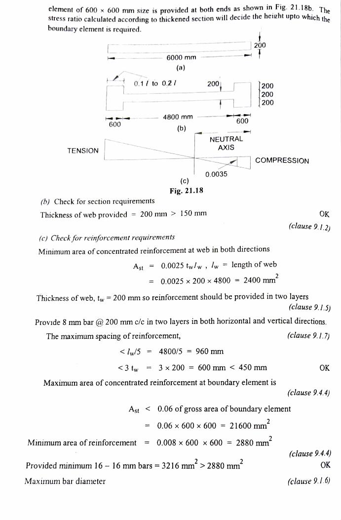
element of 600 x 600 mm size is provided at both ends as shown in Fig. 21.18b. The
stress ratio calculated according to thickened section will decide the heieht upto which the
boundary element is required.
200
6000 mm
(a)
0.1 to 0,21 200 200 200 [ 200
4800 mm 600 600
(b) NEUTRAL
TENSION AXIS
COMPRESSION
0.0035 (c)
Fig. 21.18
(b) Check for section requirements
OK Thickness of web provided 200 mm> 150 mm
(clause 9.1.2) (c) Check for reinforcement requirements
Minimum area of concentrated reinforcement at web in both directions
Ast 0.0025 twlw , lw = length of web
= 0.0025 x 200 x 4800 2400 mm
Thickness of web, tw 200 mm so reinforcement should be provided in two layers
(clause 9.I.5) Provide 8 mm bar @ 200 mm c/c in two layers in both horizontal and vertical directions.
The maximum spacing of reinforcement, (clause 9.1.7) < ly/5 = 4800/5 = 960 mm
<3 tw = 3 x 200 = 600 mm < 450 mm OK
Maximum area of concentrated reinforcement at boundary element is
(clause 9.4.4)
Ast 0.06 of gross area of boundary element
=0.06 x 600 x 600 21600 mm
Minimum area of reinforcement=0.008 x 600 x 600 2880 mm
(clause 9.4.4) OK Provided minimum 16- 16 mm bars = 3216 mm > 2880 mm
Maximum bar diameter (clause 9.I.6)

OK
n2 00 mm thick web, dh =200/10 20 mm> 8 mm
oundary element, dh = 600/10 60 mm> 16 mm
n o0
mm
thick
feach boundary element is 21.4 % of the total arca and area of web alone is 57.2 %.
OK
Design for Shear
en shear force at the bas. of wan, V=810 kN
Ihe
area of
ea
Design she
The nominal
shear stress
Vu. 810x 10 0.844 MPa
w 200x 4800
The shcare
The shear
capacity of section for ( Canacity of section for 0.25% reinforcement for M35 concrete - 0.37 N/mm
in forcement need to be provided to carry a shear force So shear.
Vu-Te bd =810 x 10-0.37 x 4800 x 200
=455 kN
Horizonta I reinforcement per m height
455x 10x 1000 = 262 mm/m
2
0.87 x 415x 4800
So rovide nunimum 0.25% reintorcement= 50 mm/m OK
Flerural strength of web
P Axial compression on wall = 1,2x 13024 15628 kN
Axial load on web = 0.572 x 15628 = 8939 kN
0.87 Oy 0.87 x 415
0.0035 Es 0.0035 x 2 x 10 = 0.515
Vertical reinforcement ratio p = Ast 2500 = 0.00261
200x 4800
0.87op0.87x 415 x 0.00261 0027 Ock 35
P cktww 35x 200x 4800
8939x 10 = 0.266
+ 20 +0.36
0.027+0.266 0.7077
2x 0.027 +0.36
Xm 0.0035 =
0.0035+0.87 oy /Es
0.003 - 0.66
0.0035+0.87 x 415/(2 x 10°))
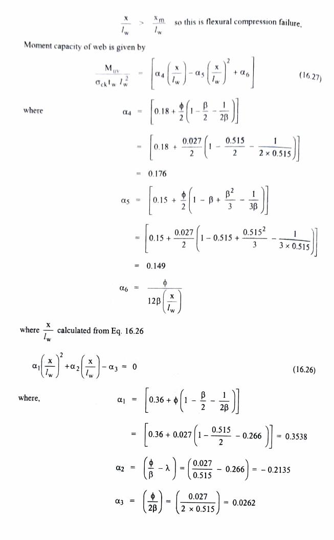
so this is flexural compression failure,
Moment capacity of web is given by
M +6 (16.27)
d4 -on- where
0.515
0.18 2 x0.515 2
0.176
,0.0271-0.515+ 0.5152 3x0.515 3
0.149
d6 F
12p
where calculated from Eq. 16.26 W
(16.26) a3 00
a 0.36+ where,
0.36+0.027 1- 0.515 - 0.266 =0.3538
2
d2 -(-)-
a3 --
0.027 - 0.266 -0.2135 0.515
0.027 = 0.0262
2 x0.515

-0.0262 -0 0.7080, - 0.1045
values of x/lw give two values of ag and Muv.
0.027 = 0.00617
12x 0.515x (0.7080) 12p
0.027 d6 and, = -0.0416
12x0.51 x (-0.1045) Eq. 16.27 gives,
35x 200 x 4800{0.17(0.7080)-0.149(0.7080) +0.00617] 9046 kNm
and,
M 35x 250 x 4800" [0.176(-0.1045) -0.149(-0.1045) -0.0416]
= - 12422 KNm
fore, adopt lower of the two values, M,, = 9046 kNm
Mu- Muv = 14523 - 9046 = 5477 kNm
Center to center to boundary element C = 6-0.3-0.3 5.4 m
Additional compressive force induced by the seismic force
My-Muy = = 1014 kN 5477
Cw 5.4
The area of each boundary element is 21.40% of the total wall. The area of web is 57.2%.
Maximum compressive force on boundary element
0.214x 1.2(8189 + 4835) + 1014 4358 kN (compression)
where load factor 1.2, DL = 8189 kN, and LL = 4853 kN as per Table 214
Maximurn tension force on boundary element
0.214 x0.8 x (8189 + 4835)- 1014 1215 kN (compression) where load factor = 0.8 as per clause 9.4.3 of IS : 13920.
There is no tension in the boundary element.Axial load carrying capacity of boundary element with minimum 0.8% reinforcement
Pu 0.4 ckAc+0.67ayAse Pu 0.4 x 35 x (600 x 600 3216) +0.67x 415 x 3216
Pu 5889 KN > 4358 KN OK
Minimum reinforcement 16-16 mm bars provided earlier in each boundary element is OK
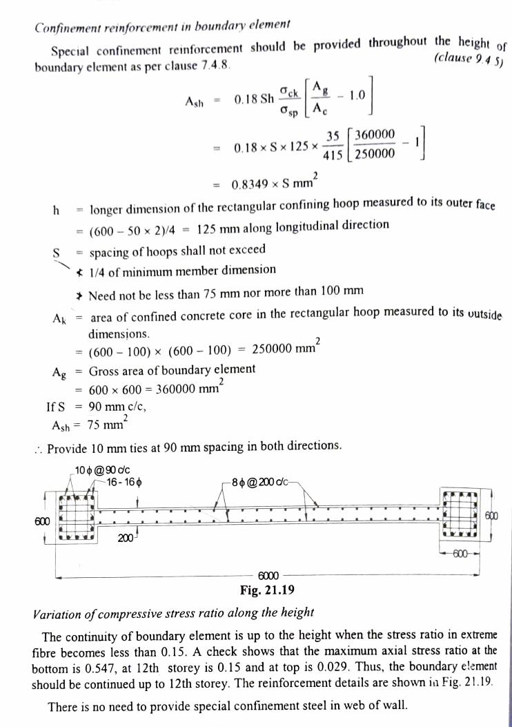
Confinement reinforcement in boundary element
Special confinement reinforcement should be provided throughout the height of
(clause 9.4 5) of
boundary element as per clause 7.4.8.
0.18 Sh ck"g10
spA Ash
0.18 x Sx 125 x 35|
360000
415 250000
=0.8349 x S mm
h - longer dimension of the rectangular confining hoop measured to its outer face h
(600 50x 2)/4 125 mm along longitudinal direction
spacing of hoops shall not excced S 1/4 of minimum member dimension
Need not be less than 75 mm nor more than 100 mm
area of confined concrete core in the rectangular hoop measured to its uutsida
dimensions. Ak
(600 100) x (600 - 100) = 250000 mm
Ag Gross area of boundary element
600 x 600 = 360000 mm
IfS = 90 mm c/c, Ash 75 mm
. Provide 10 mm ties at 90 mm spacing in both directions.
10@0 dc
16-16 8@200 dc
600 600
200 600
6000 Fig. 21.19
Variation of compressive stress ratio along the height
The continuity of boundary element is up to the height when the stress ratio in extreme fibre becomes less than 0.15. A check shows that the maximum axial stress ratio at the
bottom is 0.547, at 12th storey is 0.15 and at top is 0.029. Thus, the boundary element should be continued up to 12th storey. The reinforcement details are shown ia Fig. 21.19.
There is no need to provide special confinement steel in web of wall.