Embed Size (px)
Citation preview

Universidade Federal do Paraná
ADVANCED VERIFICATION OF
DIGITAL INTEGRATED CIRCUITS
FOR AUTOMOTIVE
APPLICATIONS
TCC 2020/2021
Daniel Rodolfo Garbi da Silva,
GRR20151339
Electrical engineering
ENSICAEN supervisor:
Matthieu Denoual
UFPR supervisor:
Bernardo Leite

TCC – Advanced verification of digital integrated circuits for
automotive applications
TCC – 2020 /2
SUMMARY 1. Abstract 4
2. Introduction 5
3. Goals 7
4. Bibliographic review 8
4.1. Digital Design 8
4.2. Digital Verification 8
4.2.1. Simulation-based verification 9
4.2.2. Assertion-based verification 11
4.2.3. Formal verification 12
4.2.4. Coverage 12
4.2.5. Regression 13
4.2.6. Environment tools and languages 14
4.3. Fault injection analysis 15
5. Methodology 18
5.1. Verification Environment 18
5.2. Fault injection analysis 18
5.3. Fault injection applied to formal verification 20
5.4. Injected faults metric computation 20
6. Results 22
6.1. Projects’ presentations 22
6.1.1. Battery Cell Controller (BCC) 22
6.1.2. BCC’s communications link 24
6.2. BCC’s simulation-based results 24
6.2.1. System & Control (S&C) IP 25
6.2.2. Event Handling (EH) IP 26
6.2.3. Primary Measurement (PM) IP 28
6.3. BCC’s formal testbenches results 29
6.3.1. Clock & Reset (clk&rst) IP 29
6.4. Communication’s link formal testbenches 30
6.5. BCC’s metric results 30
6.6. Communication’s link metric results 31
7. Conclusions and Perspectives 33

Advanced Digital Verification /3------
GLOSSARY
AA
ABIST
Advanced automotive
Analog built-in self-test
ABV Assertion-based verification
AMS Analog mixed signals
APB Advanced peripheral bus
BCC Battery cell controller
BMS Battery management system
BU Business unit
CB Cell balancing
CLK&RST Clock & reset
COI Cone of influence
CPF Common power format
DES Drivers & energy systems
DPDM Design project data management
DUT Device under test
EH Event handling
EV
FPGA
Electrical vehicle
Field-programmable gate array
FSM Finite state machine
GPIO
GUI
General purpose input/output
Graphical user interface
HEV Hybrid electric vehicle
IP Intellectual property
OOP Object-oriented programming
PL Product line
PM Primary measurement
PMIC Power management integrated circuits
POR Power-on reset
RF Radiofrequency
RTL
SOC
Register transfer level
System on chip
S&C System & control
SM Secondary measurement
SPI
SV
Serial peripheral interface
System verilog
SVA System verilog assertions
TPL Transformer physical layer
UCIF Microcontroller interface
UVM Universal verification methodology
VIP Verification intellectual property

TCC – Advanced verification of digital integrated circuits for
automotive applications
TCC – 2020 /4
1. Abstract Keywords: verification, battery management systems, digital electronics, hardware
description languages.
The automotive sector demands high quality and safety in all embedded electronic
systems that make part in their products, especially during the production of integrated circuits
(IC) and, for this purpose, the verification and validation process is mandatory. For the digital
verification, the metric-driven verification methodology is widely used, combined with code
and functional coverage data that are extracted from testbenches developed in System Verilog
UVM. The purpose of this work was to identify, analyze and implement new techniques to
further increase the reliability of the digital verification process, and apply them to NXP’s ICs.
One of these techniques, the functional verification with fault injection analysis with the
software Synopsys Certitude, allows for the detection of weaknesses and holes inside the
verification environment. This new method was applied to 14 different blocks of intellectual
properties (IP) and for one system on chip (SoC), either in simulation testbenches or formal
testbenches. This has made possible the verification of the quality of the written testbenches,
since, from the results of the activation metrics, almost all the IPs had a great code and
functional coverage, which came from the use of a random-constrained environment, with
highly randomized stimuli. Despite that, a weakness was detected for the detection capability
of the testbenches, exposing the need of the development of more assertions and checkers.
No bug was found in the design for the register transfer level (RTL), possibly due to a late
implementation of this technique in relation to the maturity of the verification. Nonetheless,
the method made possible the gathering of additional data and metrics to evaluate the quality
of the verification of digital circuits, which in turn helps support a better sign-off criterium.
Palavras-chave: verificação, sistemas de monitoramento de baterias, eletrônica digital,
linguagens de descrição de hardware.
O setor automotivo demanda uma alta qualidade e segurança nos sistemas eletrônicos
embarcados em seus produtos, principalmente na produção de circuitos integrados. Dentro
da verificação digital, são usadas as técnicas de Metric-Driven Verification, baseando-se em
dados de cobertura de código e funcionalidades extraídos de testbenches desenvolvidos em
System verilog UVM. O objetivo desse trabalho era identificar, analisar e implementar novas
técnicas para aumentar a confiabilidade do processo de verificação digital, e aplicá-las em
circuitos da NXP. A técnica de verificação funcional com análise por injeção de falhas permite
a identificação de erros e fraquezas dentro do próprio ambiente de verificação do software
Synopsys Certitude. Esse novo método foi aplicado no ambiente de verificação de 14 diferentes
blocos de propriedade intelectual (IP) e um sistema em chip (SoC), tanto em bancos de teste
de simulação, quanto banco de testes formais. Isso possibilitou a verificação da qualidade dos
testbenches escritos, dado que, a partir dos resultados das métricas de ativação, quase todos
os IPs possuíam uma grande cobertura e exploração dos estímulos de teste. Uma fraqueza
detectada por esse estudo foi uma baixa capacidade de detecção dos testes desenvolvidos,
explicitando uma necessidade de um desenvolvimento de um maior número de asserções e
checkers. Nenhum bug foi achado no design no nível de transferência de registro (RTL),
possivelmente por ter sido implementado tardiamente na verificação desses IPs. Apesar disso,
o método possibilitou maior quantidade de dados e métricas para avaliar a qualidade da
verificação dos circuitos digitais, o que possibilita um sign-off com maior qualidade.

Advanced Digital Verification /5------
2. Introduction IC design is a crucial step in the automotive sector due to the increasing embedded
technologies present in different kinds of vehicles. Especially in the electrical vehicles segment,
there are many applications, such as battery cell controllers [1] and inverter controllers [2].
These kinds of IC are classified as mixed signals and are composed of analog signals used to
monitor and measure the battery and other external peripherals, and digital signals used for
system control and processing of all the gathered data. Inside the development process, there
is a verification and validation step that is needed to ensure the quality of the device before
production and shipping.
The verification can take a big part of a product’s development cycle resources and is
responsible for guaranteeing the correctness of a design prior to its production [3]. In a digital
integrated circuit design, this is achieved by simulating the behavior of the circuit prior to its
fabrication [4]. The basis of this work is the requirements of this product, which guides the
production of the specifications by system engineers and application engineers. These
specifications are then delivered to the verification team, which uses different sets of
methodologies to certify the project. There are Hardware Descripting Languages (HDL)
testbenches, C/C++ models of the behavior, random-constrained environments with Universal
Verification Methodology (UVM) [5], formal verification etc..
The goal of this line of job is to sign-off the design, that is, to certify that the design comply
with the specifications and is well enough tested so that it can be dispatched to production [6]
[7]. For this purpose, many metrics are used to evaluate the performance of the testing, such
as code coverage and functional coverage [8]. These give a straightforward measure of how
much of the written code has been tested and how well exerted were the different functions
and states of the digital design. So, these metrics evaluate what has been tested, but do not
evaluate the correctness of the testing, and do not solely guarantee the final shipping of fault-
free devices.
Therefore, a need to evaluate the quality of a written testbench and of the verification
environment exists. For that purpose, the study of different methodologies of testing and
producing metrics is deemed necessary. This study discusses the implementation of fault
injection analysis, a technique that evaluates the quality of a testbench and its checkers by
emulating a faulty design and determining whether the verification environment can detect
the injected error. This methodology introduces new metrics and sign-off points that further
help the verification job [9].
This project was developed inside NXP Semiconductor, a leading company in the
semiconductor’s automotive sector, and where I worked as an intern during six months as a
part of the Driver & Energy Systems (DES) verification team. The verification team of NXP’s

TCC – Advanced verification of digital integrated circuits for
automotive applications
TCC – 2020 /6
product line (PL) DES is based in Toulouse and is responsible for testing and simulating the
design of mixed signal integrated circuits for the automotive sector, such as battery cell
controllers, gate controller drivers and communication’s links. The team faced this problematic
and wanted to experiment on implementing new methodologies in its verification flow that
could potentially help find bugs faster and not let critical ones escape into design production.
For this reason, this project focused on the implementation of a fault injection analysis tool,
Certitude, into NXP’s flows and how it helped direction the development of testbenches and
produce more metrics and data to reach the sign-off point.

Advanced Digital Verification /7------
3. Goals The main goal of this study was to analyze the new methodologies that could be applied to
the digital verification of mixed signals ICs, and how their added metrics contributed to a safer
product and better sign-off criteria. These methods could potentially show weaknesses or holes
in the testbenches that could hide bugs in the digital design.
The specific goals of this project were:
• analysis of the effort of implementing a new methodology in the existing verification
environment, based on metric-driven verification.
• implementation of a functional qualification tool, Synopsys Certitude, on a battery
management system IC project and on a driver controller project.
• generation of additional metrics based on the fault injection analysis to reach a sign-
off point for the verification.

TCC – Advanced verification of digital integrated circuits for
automotive applications
TCC – 2020 /8
4. Bibliographic review
4.1. Digital Design
In a digital design process, there are different levels of abstraction that need to be
considered: system-level, RTL, logical, and physical level. Starting from the top, the system-
level design is a planning of the functions of the integrated circuit, how it interacts, especially
with the analog signals. The RTL design is an abstraction of the behavior of the circuit that uses
digital components, like adders and state machines, which are modeled by a hardware
description language (HDL) such as Verilog. The logic synthesis maps the RTL into a gate-level
netlist, that contains all the logic of the circuit, but without timing constraints. The physical
design takes the netlist generated, and adds the floorplan and timing constraints, to produce
an optimized physical layout that can be shipped to a foundry and fabricated. [10]
This study focuses on the RTL level of the digital design. To ensure the quality of the
developed hardware, testing is essential, and the digital verification is the key.
4.2. Digital Verification
Verification is a crucial part of a digital circuit chip’s development; it cross-checks a product
design to its specifications and requirements. This is achieved by simulating the behavior of
the design prior to its fabrication, either with mathematical models or emulated models. This
can be done with classical simulation, assertion-based verification, or formal verification. The
first instantiates and emulates a model of the physical design and stimulates its inputs to drive
its signals. The assertions are statements that formally specify a design’s intended behavior.
The formal verification uses mathematical tools to model the design and extensively explore
all the possible input and state combinations. In the following section, different techniques
commonly used for digital verification will be discussed, including the one for which the
implementation was the object of this study, the fault injection analysis.
The first technique discussed will be the classical simulations. With this method, the behavior
of the design can be explored by stimulating the internal logic with an external driver. From
the amount of the code that is stimulated by these signals, you can measure how well your
design is covered by your tests and a checker at the output of the design compares the outputs
to a known model’s output. [11]
Further on, assertion-based verification can be added on top of this. By adding assertions
to the simulations, you can verify during runtime the intended behavior of the design and
whether it is respected. This provides a clearer view of the design’s conformity to the
specifications, since it provides a pass or fail result before analyzing the waveform generated
by the simulation. [12]

Advanced Digital Verification /9------
The formal tool is another approach to the verification. It does not rely on the specification
of stimuli, neither of a written testbench to drive the design, instead relying solely on the RTL
and the assertion’s written to specify the design’s intended behavior. Based on this, it generates
extensive inputs that cover all possible states and apply them on the RTL using mathematical
models of the design. [13]
All of these techniques help explore the design and determine the quality of the written RTL,
but the metrics for the quality of the verification – mainly being a measure of the amount of
the code or functions that have been covered – do not include the quality of the verification.
That is why this study focuses on the implementation of fault injection analysis, a technique
that can help identify whether your verification environment notices faulty behavior on the
design. In the next sections, all these methodologies will be covered.
4.2.1. Simulation-based verification
A design can be tested using a simulation-based verification as the scheme from Figure 1.
The design under test (DUT) is exposed to a stimulus: an input vector that represents a real use
case of the device and will drive its inputs. These stimuli can propagate the logic inside the
DUT until its outputs, where a checker is connected to monitor the design’s behavior.
Figure 1: simulation-based verification diagram [14].
Simulation-based verification is as good as the written input drivers, which will influence in
how the design logic is exerted. It also depends on the development of a testbench and a
complete verification environment. In the next subsections, the tools used on the testbench
development are described.
System Verilog testbench
System Verilog (SV) is a hardware description and hardware verification language derived
from Verilog that can be used to model, design, simulate, test, and implement electronic
systems. The digital designs verified at NXP are made of a mix of Verilog and System Verilog
files, but the verification environment is mainly coded on SV. Verilog is a subset of SV since all
its features are available. When SV is applied to verification and testbench development, it uses
extensive object-oriented programming (OOP) and these constructs are generally not
synthesizable. [11]

TCC – Advanced verification of digital integrated circuits for
automotive applications
TCC – 2020 /10
Figure 2: system Verilog testbench [11].
Figure 2 shows the composition of a testbench written in SV and based in OOP. There are
some components that can be re-usable and scalable to create different tests. An interface is
used to link the test environment to the DUT signals. This interface will be used directly by the
driver and the monitor. The former is responsible for driving the input signals of the DUT based
on a generated stimulus, while the latter captures the activity of the design through its inputs
and outputs. Finally, the scoreboard cross-checks the outputs behavior related to a model and
its expected output.
Testcases and environment
The components described before are contained inside an environment, that can be
included by a test and configured based on the desired use case. A testcase is a developed set
of instructions that mimics a real case use scenario of the intended product. It specifies the
driven inputs and the expected outputs based on a model to achieve a specific objective,
exercising a specific path of the design.
UVM
The Universal Verification Methodology (UVM) is a standardized methodology for the
verification of integrated circuit designs and is packaged as a class library written in System
Verilog. It allows for generic testbench generation, random stimuli generation, and
development of reusable verification components. A verification methodology adds the
development of a plan based on the statement of the function of the design. Also, it adds the
automatization of the process and collection of metrics. The development of checkers,
constraints and a cover model can result in improved quality of the verification [5] [15].

Advanced Digital Verification /11-----
-
Checkers ensure functional verification and are developed using assertions or procedural
code. Coverage measures the completeness of the testing and are useful to provide metrics of
the verification. Constraints shape the stimuli into realistic and possible cases that are relevant
to the DUT. Figure 3 shows an example of a testbench based on this methodology.
Figure 3: simulation-based verification with constrained random stimulus [16].
To exercise these stimuli, tests must be written to drive the inputs and implement the
checkers and coverage parameters. There should be a mix of directed tests to exploit the design
and afterwards develop fully random sequences to explore different state spaces. This
methodology allows for the reuse of verification IPs (VIP), allowing for flexible testbench
designs and device configurability.
4.2.2. Assertion-based verification
The assertion-based verification (ABV) speeds up functional verification that can be used
during simulation [12]. An assertion is a statement of a design intended behavior. It does not
describe the element; its purpose is to ensure that the specifications are respected on the
design. It evaluates to true when its expression is true, and it reports an error when its
expression is false. Assertions should also include coverage properties – which will be specified
in section 4.2.4 below – that helps identify the completeness of the set of developed assertions
[17].
Assertions can be embedded into the design, built into the verification environment, or be
provided by a third party in a library. The languages can be either System Verilog Assertions
(SVA) or Property Specification Language (PSL). Assertions can either be concurrent – must
always be satisfied – or temporal – must be satisfied under clocking conditions, individually or
as a sequence.

TCC – Advanced verification of digital integrated circuits for
automotive applications
TCC – 2020 /12
4.2.3. Formal verification
Formal verification is a mathematical tool complementary to simulation that proves specific
design properties written as assertions or cover groups, for example. Instead of simulating the
behavior of the design, the tool makes a mathematical abstraction and without specific
correspondence between the model and the physical representation. This method is exhaustive
as it covers all input scenarios and can easily explore corner cases. It does not require stimulus
nor a testbench [13].
Figure 4: formal verification techniques [13].
Figure 4 shows different formal techniques. Model checking is used on the Cadence
JasperGold’s Formal Property Verification (FPV) app to prove different assertions and cover
points developed for the design. It will recreate a model of the system and exhaust all its
possible behaviors and verify that the specified for all cases. If not, a counterexample is created
that can be used to create a waveform of the violating behavior of the design.
4.2.4. Coverage
The verification is a never-ending process, it is not possible to determine when every bug
inside the design has been found, but there are metrics that help indicate the completeness of
the verification. Coverage will indicate how much of the design has been exerted with the
verification. It can either be an implicit process – where data is gathered without any additional
coding –, or an explicit process – where additional coding of assertion or coverage statements
is needed. Figure 5 shows different kinds of coverage: code coverage, functional coverage, and
assertions [8].

Advanced Digital Verification /13-----
-
Figure 5: different types of coverage [18].
Code coverage
Code coverage can help identify parts of functionality that have not yet been tested but
cannot identify if there is any missing functionality on the design. It is based on the parts of
the source code that have been exerted, either by simulation or by formal verification. It can
be divided into different types of coverage: line, statement, branch, expression, state, or toggle
[8].
Functional coverage
Functional coverage requires additional coding since it is an active monitoring of the
execution of a test. It indicates whether certain values or sequences based on the specifications
have been explored on the DUT with the developed tests. It is especially necessary when you
have a random-constrained environment, since it will be indicated which values are being
explored by the randomization process of the input stimuli. It is usually explored with written
cover properties.
4.2.5. Regression
Regression is based in multiple reruns of functional and non-functional tests, ensuring an
operability of the developed software after changes related to bug fixing and specification
changes. It consists of a run of all the developed testcases of the verification environment and
metrics collection related to these simulations. It also includes the formal verification proofs.
Keeping track of all the developed tests, those that pass and those that fail with each iteration,
and reporting metrics related to the coverage for each run is a used to assess the progress of
the verification team.
Inside the team, Cadence’s Vmanager is used to keep track of all the developed tests for the
designs and are used to launch the regression. Combining it with a random-constrained
environment, it is useful to find the most successful seeds to the randomization process that

TCC – Advanced verification of digital integrated circuits for
automotive applications
TCC – 2020 /14
will explore corner-cases and the most out of the DUT. The seed is a number that initializes the
pseudorandom number generator.
4.2.6. Environment tools and languages
Enovia dPDM
The hardware design product data management (dPDM) is a system that provides
consistency and visibility for chip design inside NXP. The tools of this system most present
during daily work are the PiPA and Design Sync. The first is responsible for setting up and
managing workspaces and providing a command line interface to the server; the latter is the
tool for file versioning and configuration management across the server.
PiPA provides an encapsulation for all installed tools and allows for the compatibility
between environment for all people working on the same project. It sets up several
environment variables and runs checks to detect mismatches for tools, technology, blocks, and
the environment. It is the starting point for accessing all software related to design and
verification. Design Sync will allow the file versioning on projects. It populates the local
workspaces with links to files cached on the server or can create locked local copies that allow
for user modification. It is also possible to create different tags for versions of entire
workspaces, blocks, or folders.
Bash, TCL, Makefile and Python scripting
Scripting languages are widely used in the verification flow in different levels. Bash is used
for direct simulator calls, as well for parallel job managing and dispatching. It is also used inside
of Synopsys Certitude configuration to create the compilation and simulation execution scripts.
Makefiles are used to set all environment variables and to launch different tools. Tool command
language (TCL) is used mainly for configuration of the tools, including Cadence’s NCSIM and
JasperGold as well as Synopsys’ Certitude. Python is used for high level encapsulation calls to
facilitate the launching of the regression or standalone simulations.

Advanced Digital Verification /15-----
-
4.3. Fault injection analysis
In Figure 6, there is a diagram of the concept of fault injection analysis. For this analysis,
faults are injected into the RTL code that describes the design. These faults are implemented
by mutating the original code into a faulty version where statements can be inversed, signals
can be stuck, or assignments can be altogether ignored. The different kind of faults that can
be injected will be discussed further ahead. Then, with one fault injected at a time, the
verification environment is run. Its status, either pass or fail, will determine if it has detected
the faulty behavior. In the case where the test suite encounters no errors, it points to a hole or
a weakness in the testbench.
Figure 6: Synopsys Certitude fault injection concept [19].
This analysis adds some metrics to the coverage and classical simulations since it can
measure the overall quality of the checkers developed. The code coverage can show which
parts of the code have been exerted, but it doesn’t show whether there has been a specific
check for each part of the code. It is important to note that no faults are injected in the
testbench code.
In this analysis, there are some concepts introduced: activation, propagation, and detection
[19]. The activation is analogous to coverage and will express whether a stimulus covered the
statement in which the fault was injected. The propagation is the capability of the specified
stimuli to transport the error to an observable port, in other words, it means that the fault has
induced a change into the output behavior. The detection is the reporting of the error that has
been propagated to the output; it can be a comparison between the design and a model or a
failed assertion. Figure 7 show these concepts in the testbench.

TCC – Advanced verification of digital integrated circuits for
automotive applications
TCC – 2020 /16
Figure 7: Artificial bug behavior when injected on the DUT [19].
Only the faults that are activated and propagated are qualified. These faults can be
grouped into different classes depending on their role on the design. Table 1 shows related
classes:
• Connectivity: can be either a port stuck at a specific value or inversed. These can
be injected in the top cell outputs and in the inputs of instantiated modules.
• Reset: those are injected in asynchronous resets, forcing their conditions to
always be true.
• Clocked process: these are faults injected on synchronous statements.
• Combinatorial process: these are faults injected on asynchronous statements.
• Control flow: these are faults injected in control conditions, such as ifs, conditional
operators, and switch cases.
Table 1: Different classes of injected faults.
From the 5 different fault classes, the connectivity and reset classes are the most critical.
Since the connectivity influences directly on the propagation of the signals, a bug where an
output port or an internal connectivity signal does not perform as expected can directly
influence on the output of the circuit. The reset class can indicate whether a flip-flop performs

Advanced Digital Verification /17-----
-
as expected: in the case where a fault is injected in the reset and it is not detected, it can
highlight a major functional bug.
Table 2 shows the possible status of each individual fault after the qualification run. Non-
activated faults are shown in yellow, non-propagated faults, in orange, detected faults, in green,
and non-detected faults, in red. Non-detected and non-propagated faults can lead to dropped
faults: these faults are considered to be under the cone of influence of the non-detected or
non-propagated and consequently would just lead to wasting computational efforts. The
dropped faults are not qualified until there is a fix for the non-propagated or non-detected
fault.
Table 2: Outcomes of fault qualification.
Figure 8 shows an example of an injected fault. This output was in the top RTL file of an IP.
There are three different types of faults injected: OutputPortStuckAt0, OutputPortStuckAt1 and
OutputPortNegated. Each one is an individual fault and must be run separately, the detection
of one of them do not imply on the detection of the others. It is also shown the change made
into the code for the specific port.
Figure 8: Injected fault and its respective status.

TCC – Advanced verification of digital integrated circuits for
automotive applications
TCC – 2020 /18
5. Methodology
5.1. Verification Environment
For the verification environment, Cadence Incisive and Cadence Vmanager were the two
used software, while the Verification IPs (VIP) and the digital designs were written either in
Verilog or System Verilog.
Incisive is a suite of tools for the design and simulation of ICs, SoC and field-programmable
gate arrays (FPGA). It was used for simulating the entire digital design of the project, including
the verification IPs. Some of the IPs had already a working environment running Cadence’s
Xcelium – a similar tool as Incisive, but more up to date. [20]
Cadence’s Vmanager is an automated verification planning and management solution. This
tool made possible the automation of the regression runs, as well as metrics collection,
primarily coverage metrics. The regressions were launched from Vmanager’s graphical user
interface (GUI), and the tests to be run were specified in the verification session input format
file, with the .vsif extension.
Verilog and System Verilog were the chosen hardware description languages for the
development of the digital design and the verification environment. Those languages were
chosen since Verilog is widely spread inside the automotive sector, and SV provides an OOP
extension, that makes possible the encapsulation and reusability of the testbench code.
5.2. Fault injection analysis
The software used for the fault injection analysis, Synopsys Certitude, had to be used
following a certain methodology that can be applied to the concept of the qualification. The
run of a fault injection qualification is divided into different phases:
• Model: in this phase all the RTL files are parsed, and the code is instrumented.
Instrumentation is the process of modifying the original source, adding a mechanism
of fault injection and monitoring. This phase outputs all the faults that are going to
be used in the qualification.
• Activation: in this phase, a full regression is run using the instrumented code. The
instrumentation will help gather information regarding the activation and
propagation of the faults and their influence. This phase is crucial for the tool to
familiarize itself with the verification environment and gather statistics regarding the
interaction testcases – faults.

Advanced Digital Verification /19----
--
• Detection: in this phase, each fault is triggered individually and all the testcases that
activated this fault are run. As soon as a testcase detects the fault (fails), all the other
testcase runs are killed.
Figure 9: Synopsys Certitude qualification phases flow.
As shown in Figure 9, these phases should be run in order, since each one of them feeds
data into the next one. In the model phase, no testcase data is used, only the design files should
be specified, and the top file indicated. The instrumented code is produced by the analysis of
these files and is necessary for running the activation. Now at the activation phase, testcase
data is needed, and they should be specified for the tool. This produces data regarding the run
of all testcases and the coverage of the code and its functions and helps guiding the detection
phase. Finally, at the detection phase, the big computational power is used to run every test
that has activated a fault until at least one of them fails. Since this must be done for all faults,
in the worst-case scenario, this phase will have as many processes of testcases running as the
multiplication of the number of faults with the number of testcases.
This process is not static but rather iterative. As soon as the three phases are run for the
first time, there should be a review of the results. The addition or modification of checkers can
help detected some of the non-detected faults. The addition or modification of a testcase can
help explore corner-cases and propagate previously non-propagated faults. At last a bug in
the RTL might be found and a change in the design may be of use.
Not all these modifications must lead to an entire rerun of the tool. If only some checkers
were added to target specific faults, there can be a standalone run of the detection phase only
for the faults affected by the checkers. On the other hand, if there is a testcase modification,
the activation phase must be run, followed by the detection phase again. And in the last case,
when the design is changed, there must be an entire rerun including the model phase.

TCC – Advanced verification of digital integrated circuits for
automotive applications
TCC – 2020 /20
This workflow allows for an iterative use of the software alongside the development of
the testbench. This can also provide a useful guide for assertion developing, since it will
highlight the statements that aren’t checked.
5.3. Fault injection applied to formal verification
Until this section, all information about the fault injection analysis was based on a dynamic
flow, with classical RTL simulation. A formal testbench can also be used with fault injection
analysis with some little adaptation. The differences start on the propagation, since this concept
is not applied to formal verification, and that the activation and detection instrumented code
are identical, since there is no need to collect data for the propagation. Also, a testcase in
formal verification has a different notion: it is a group of properties, either assertions, cover
points or constraints.
The methodology remains the same, as well as the phases of the tool. Since the tool is
exhaustive, the reviews are mainly focused on the completeness of the set of properties
developed. On the default run, only assertions are considered for qualification and detection
of faults, but, if deemed appropriate by the verification team, cover properties can also be
added to the set – a fault is detected when a cover property turns to be unreachable.
5.4. Injected faults metric computation
The tool that performs fault injection analysis also offers another method of qualifying the
verification environments based on a metrics analysis. It is a statistical analysis that selects a
sample of random faults in the design, ignoring the faults status of previous runs, and executes
random testcases for each of these randomly picked faults. These results are a measure of the
overall quality of the verification environment divided into 4 variables:
• A/F: percentage of activated faults over the number of injected faults. This is the only
metric that is absolute, since it is based on the activation phase.
• P/A: percentage of propagated faults over the number of activated faults. This
analysis will measure the quality of the stimuli developed for the testbench and how
well they can exert the faults and make them visible at the output probes.
• D/P: percentage of detected faults over the number of propagated faults. This
parameter will measure the detection capability of the environment given that the
fault has been propagated and the quality of the developed checkers.
• D/F: percentage of detected faults over the total number of faults. This is a global
metric that will evaluate the quality of the stimuli, the developed tests, and checkers.

Advanced Digital Verification /21-----
-
Each metric has a proposed target for the sign-off, that can be adjusted depending on the
demands of the user. For example, the tool’s default target, which was recommended by the
vendor, was: 90% for A/F, 80% for P/A and 95% for D/P.

TCC – Advanced verification of digital integrated circuits for
automotive applications
TCC – 2020 /22
6. Results The main goal of this project was to analyze the feasibility of the implementation of fault
injection analysis on the existing workflow of the verification team based in NXP Toulouse. The
tool was run in multiple environments, starting off from 7 different IPs in a battery cell controller
(BCC). It was then extended to the formal verification in a communication link for BCCs, and to
the later developed formal testbenches for 2 other IPs of the BCC. It was also extended to a
non-UVM regression suite of an electrical vehicle (EV) inverter controller.
One of my contributions to this project was the development of all the environment needed
for implementing the new methodology on the workflow of the company. That meant creating
scripts in bash and python for each one of the IPs to effectively launch the tool with the correct
configurations. I was also responsible for analyzing all the data gathered from this tool and
pointing out where the team could improve in the testbenches in order to, first, improve the
quality of the testbenches and, second, improve the metrics of the reports.
In the next sections, there will be a brief explanation of the projects in which this
methodology was applied. Afterwards, there will be a review of the results of the most
significant IPs, either on classical simulation testbenches or on formal verification, and then the
results of the metric computation of the injected faults will be reviewed.
6.1. Projects’ presentations
6.1.1. Battery Cell Controller (BCC)
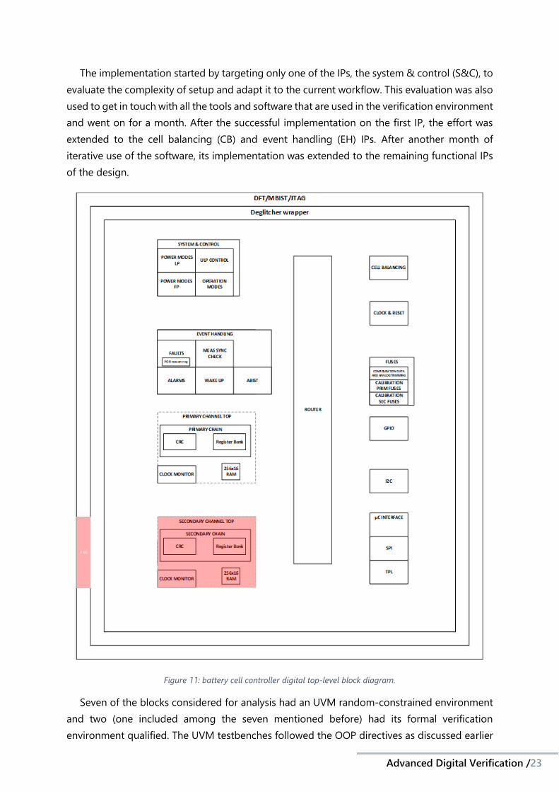
The BCC is a battery cell controller for EV and hybrid electrical vehicle (HEV). It is composed
of an analog circuit and a control, communication and fault handling digital circuit. Figure 10
shows an example of a commercially available IC with this functionality and Figure 11 shows a
diagram of the top-level block diagram of this IC. The highlighted area offers a JTAG
connection. It is composed of many smaller blocks – IPs – either analog or digital. The
functional qualification was applied to the digital design of this product and the goal was to
implement the tool Synopsys Certitude on the IP level verification.
Figure 10: NXP's commercially available BCC.
Advanced Digital Verification /23----
--
The implementation started by targeting only one of the IPs, the system & control (S&C), to
evaluate the complexity of setup and adapt it to the current workflow. This evaluation was also
used to get in touch with all the tools and software that are used in the verification environment
and went on for a month. After the successful implementation on the first IP, the effort was
extended to the cell balancing (CB) and event handling (EH) IPs. After another month of
iterative use of the software, its implementation was extended to the remaining functional IPs
of the design.
Figure 11: battery cell controller digital top-level block diagram.
Seven of the blocks considered for analysis had an UVM random-constrained environment
and two (one included among the seven mentioned before) had its formal verification
environment qualified. The UVM testbenches followed the OOP directives as discussed earlier

TCC – Advanced verification of digital integrated circuits for
automotive applications
TCC – 2020 /24
in the bibliographic review, therefore many components and blocks of code for the testbenches
were reusable, and they were easily integrated between different hierarchical levels.
Each one of the individual IPs that were part of the design of the IC had its testbench (either
formal or simulation) and had a regression running. The regressions were used to ensure the
compliance of all IPs during the design review and the addition of new testcases. Some
regressions were made up of around 30 runs of tests with different seeds for the randomization,
while other had as many as 1000 runs of smaller tests totally randomized. Gathered data from
these regressions included code coverage and functional coverage, and were the main metrics
used for verification feedback.
6.1.2. BCC’s communications link
This IC is an isolated high-speed network transceiver & router that can be used to link and
create a chain of BCC ICs. It is isolated from the high voltage power domain that comes from
the battery cells. Amongst many different IPs that make up the project, a set of interfaces was
verified using formal testbenches. These were the first attempt of implementing Certitude on
a formal environment inside the workflow of the company.
Six formal testbenches had been developed for the interface IP designs: RX FIFO, TX FIFO,
TPL serial adapter, TPL TX time slicing, serializer and deserializer. These IPs were simple
compared to the ones on the first mentioned project, and the verification was quicker than
before and there were not as many hierarchical levels inside the design to add complexity.
6.2. BCC’s simulation-based results
Table 3 shows the results computed for all the IPs for the run over the UVM simulation
environment. Each IP had different size, from the smallest – the I2C which had only 1767 faults
injected – to the biggest – the primary measurement (PM) which had 16870 faults injected. The
IP with the lowest number of dropped faults was the event handling (EH): it means that the
detection could advance deeper into the design without encountering non-detected faults that
masked most of its behavior. This is because the EH was the block that had the highest number
of reviews and that had a robust verification environment (VE), it is possible to see this with the
high number of detected faults relative to the other blocks. Also, the S&C, even though it was
the first to be implemented and that it was well verified, still had a high number of non-
detected, which will be discussed ahead.
Some relevant results are highlighted on the summary’s table, including: the IP that had the
highest number of non-detected faults, the S&C; the IP with the highest number of detected
faults, as well as the smallest number of non-activated faults, the EH; the highest number of
non-propagated faults, for the SM; and the highest number of dropped faults, for the PM.

Advanced Digital Verification /25----
--
Table 3: BCC summary of IP Certitude run results.
For each of these IPs, these results helped shape the verification efforts to have a higher
quality of the testbenches. For each of the IPs, there were reviews of the code written for the
testbenches, to improve the quality of the checker and the coverage of the written assertions
and cover properties.
The interpretation of these numbers depend on the user needs and context for the IP.
Depending on the level of safety required for the product, these numbers should be as low as
possible, otherwise, it is important to balance the verification effort. To bring the number of
non-activated, non-propagated and non-detected faults down, many iterations are needed,
and thus the complexity of the testbenches and tests grow. For the needs of the project, these
results were satisfactory, with some exceptions, because none of these faults revealed a major
functional design bug, revealing instead a number of possible testbench improvements.
In the next sections, the improvement of the status of the faults and consequently the
improvement of the quality of the testbench brought by the reviews will be discussed for the
most significant IPs.
6.2.1. System & Control (S&C) IP
The S&C block is an IP that implements and manages the states of the IC, that saves its
configuration status and adapts the trimming of the oscillator. It was the first IP worked on and
served as a ramp-up to get to know the workflow. Table 4 displays the results for the S&C IP
functional qualification.
Class Name Faults
in Report
Non-Activated
Non-Propagated
Detected Non-
Detected
Disabled by
Certitude
Disabled by User
Dropped
TopOutputsConnectivity 287 4 0 266 11 1 0 5 ResetConditionTrue 38 0 1 35 0 0 0 2 InternalConnectivity 456 13 8 261 20 15 0 139 SynchronousControlFlow 73 0 0 52 1 0 0 20 SynchronousDeadAssign 33 0 1 28 0 3 0 1 ComboLogicControlFlow 426 0 19 111 14 6 0 276 SynchronousLogic 105 0 0 63 4 1 0 37 ComboLogic 1322 0 19 401 99 31 0 772
Total 2740 17 48 1217 149 57 0 1252
Table 4: S&C Certitude run results.

TCC – Advanced verification of digital integrated circuits for
automotive applications
TCC – 2020 /26
The first three classes are critical, since they are related to connectivity and resets, as
described earlier in the bibliography review, and from the other classes, the
SynchronousControlFlow is the most important, since it impacts directly on the flow of the
circuit’s logic. So, focusing on the first four classes, we still have 32 non-detected faults, that,
on this case, turned out to be highly influenced from the IPs low-power management
simulation tool, embedded on Cadence Incisive’s.
Figure 12 shows the evolution of the IP’s faults status as it was being reviewed and iterated.
This IP had excellent activation and propagation results, but the detection score was not very
high.
Figure 12: S&C fault status evolution in time.
As more iterations were done and the qualification went deeper into the design, it showed
us more non-detected faults, especially in the FSM files. These faults related to the FSM files
had this result because their influence was so small that they fell inside the testbench tolerance
for the transients. So, they didn’t impact much on the quality of the verification environment.
6.2.2. Event Handling (EH) IP
The EH IP generates output signals depending on fault conditions. It generates fatal internal
faults that triggers a power-on reset (POR). The origin of the fatal fault and its reason is then
saved in a system register, and it remains stored until the register is either read or reset. It saves
caught faults into a register: supply, measurement, communication and analog faults; and
0
500
1000
1500
2000
2500
3000
1st iteration 2nd iteration 3rd iteration
S&C Evolution
Non-Activated Non-Propagated Detected Non-Detected
Disabled By Certitude Disabled By User Dropped Not Yet Qualified

Advanced Digital Verification /27----
--
outputs them. It is configurable to either generate an alarm or a wakeup signal. Finally, there
is an analog built-in self-test (ABIST) that can automatically run checks on the analog circuits.
Table 5 shows the results for the EH IP Certitude run. It is notably the only IP that reached
zero non-detected faults for the first four fault classes. This is a good sign-off point. It also has
the lowest number of dropped faults – only 5,6% – and the highest number of detected faults
– up to 85,6% of the design. The design is almost entirely activated since it is a highly
randomized random-constrained environment.
Class Name Faults
in Report
Non-Activated
Non-Propagated
Detected Non-
Detected
Disabled by
Certitude
Disabled by User
Dropped
TopOutputsConnectivity 137 0 0 122 0 2 13 0 ResetConditionTrue 58 0 1 55 0 2 0 0 InternalConnectivity 1513 0 13 1353 0 146 1 0 SynchronousControlFlow 151 0 6 143 0 2 0 0 SynchronousDeadAssign 56 0 3 48 0 3 1 1 ComboLogicControlFlow 784 2 30 641 5 19 15 72 SynchronousLogic 277 0 14 240 1 3 3 16 ComboLogic 1498 1 4 1229 8 85 1 170
Total 4474 3 71 3831 14 262 34 259
Table 5: EH Certitude run results.
Figure 13 shows the evolution of the results while running the tool iteratively with the VE
modifications. During its reviews, the number of detected faults increased from around 1600
to around 3800. The first three iterations showed minor changes related to added seeds,
modified checkers and increase of the test’s constraints. A huge increase is seen from the third
iteration to the fourth. This was caused because a specific seed was added to explore a non-
propagated fault, which was then stimulated and impacted on 1500 other faults.

TCC – Advanced verification of digital integrated circuits for
automotive applications
TCC – 2020 /28
Figure 13: EH fault status evolution in time.
6.2.3. Primary Measurement (PM) IP
The PM digital IP is responsible for the analog controls of the ADCs that measure the
battery’s cell voltages, calculates its values with integrated DSP’s and store these results in
RAM. Table 6 shows the Certitude run results for this IP. It is the largest block for the BCC IC
and had 14256 faults to be qualified, but, even though it was well covered and activated, many
faults were dropped during the qualification. This was the result of many
TopOutputsConnectivity faults being non-detected, further causing the highest dropping ratio
in all the IPs.
Class Name Faults
in Report
Non-Activated
Non-Propagated
Detected Non-
Detected
Disabled by
Certitude
Disabled by User
Dropped
TopOutputsConnectivity 221 1 0 143 27 1 0 49
ResetConditionTrue 27 0 0 9 0 2 0 16
InternalConnectivity 1453 9 2 58 8 116 0 1260
SynchronousControlFlow 226 0 0 8 0 14 0 204
SynchronousDeadAssign 22 0 0 4 0 0 0 18
ComboLogicControlFlow 3254 51 18 212 15 8 0 2950
SynchronousLogic 189 0 3 5 0 20 0 161
ComboLogic 8864 0 49 58 0 284 0 8473
Total 14256 61 72 497 50 445 0 13131
Table 6: PM Certitude run results.
0
500
1000
1500
2000
2500
3000
3500
4000
4500
5000
1st 2nd 3rd 4th 5th
EH Evolution
Non-Activated Non-Propagated Detected Non-Detected
Disabled By Certitude Disabled By User Dropped Not Yet Qualified

Advanced Digital Verification /29----
--
6.3. BCC’s formal testbenches results
6.3.1. Clock & Reset (clk&rst) IP
The clk&rst IP is responsible for generating all clocks and resets on the system based on the
high frequency oscillator. It is the smallest IP from the BCC that Certitude functional
qualification was implemented on. Table 7 shows its latest run results, the high number of
“disabled by user” faults is due to the many test related signals that are not verified. Also, due
to a Formal Flow integration issue, all TopOutputsConnectivity faults are InternalConnectivity,
but this does not influence on the qualification.
Class Name Faults
in Report
Non-Activated
Detected Non-
Detected
Disabled by
Certitude
Disabled by User
Dropped
TopOutputsConnectivity 0 0 0 0 0 0 0 ResetConditionTrue 15 0 8 4 1 1 1 InternalConnectivity 376 0 212 2 11 109 42 SynchronousControlFlow 27 0 9 1 4 0 13 SynchronousDeadAssign 12 0 3 0 0 0 9 ComboLogicControlFlow 58 0 16 0 0 18 24 SynchronousLogic 36 0 22 0 1 0 13 ComboLogic 197 0 70 0 19 19 89
Total 721 0 340 7 36 147 191
Table 7: Clock & Reset Certitude run results.
The challenge on this IP was considering explicit cover properties for the qualification. By
default, Certitude only considers assert properties for fault detection and does not consider
unreachable cover properties as a proof fail. Many signals in this IP could only be verified given
a precondition – which had a related cover property – but some faults turned these
preconditions unreachable. Therefore, two different runs were done: one of them had no
activated cover properties for detection and the second one had covered all cover properties
activated. The different results can be seen on Figure 14.
Figure 14: cover properties impact on detection.
0
200
400
600
800
disabled enabled
Cover Properties impact on clk&rst
Non-Activated Detected Non-Detected
Disabled By Certitude Disabled By User Dropped

TCC – Advanced verification of digital integrated circuits for
automotive applications
TCC – 2020 /30
On the first run, there was a high number of non-detected Connectivity faults, those were
all influenced by the unsatisfied cover precondition. There were also some non-activated faults
that happened to only be verified by cover properties. On the second run, the number of
detected faults was doubled and the non-detected dropped drastically, leaving mostly some
reset related faults yet to verify.
6.4. Communication’s link formal testbenches
The communication’s link was composed of 6 different IPs. Each of these IPs had its own
environment for the tool and had its separate review, but, since they were fairly small the results
were merged into one report and are shown in Table 8. The ResetConditionTrue non-detected
faults pointed to some features that were not-being tested, for example a whole flip-flop whose
driven signal was not verified. The non-activated faults also pointed to an added output that
had not yet been verified. Other than that, the results were good and certified the quality of
the written assertions and formal testbench.
Class Name Faults
In Report
Non-Activated
Detected Non-
Detected
Disabled By
Certitude
Disabled By User
Dropped
TopOutputsConnectivity 99 3 93 0 0 3 0 ResetConditionTrue 25 0 22 2 0 0 1 InternalConnectivity 39 0 24 0 15 0 0 SynchronousControlFlow 153 0 79 10 0 0 64 SynchronousDeadAssign 7 0 5 0 0 0 2 ComboLogicControlFlow 74 0 48 1 0 0 25 SynchronousLogic 121 0 37 0 0 0 84 ComboLogic 181 2 93 2 6 0 72
Total 699 5 401 15 21 3 248
Table 8: BCC's communications link interfaces Certitude run results by fault class.
6.5. BCC’s metric results
Figure 15 shows the metric computation for all the blocks using random-constrained
simulation on this project. As mentioned earlier in the bibliographic review, these values have
a proposed sign-off target, that are subjective, but are useful for measuring the quality of the
verification environment. This project’s targets were the default targets from the tool, that were
recommended by the vendor.
The first conclusion taken from these results is the high quality of activation on all the IPs,
they all had the A/F well over the desired target. This is a reflex of the used strategies and
metrics until now: the verification was based on code and functional coverage, which led to a
high exploration of the entire design. The P/A had good results as well and was always inside
the defined metrics for the propagation.
A weakness was seen by looking into the D/P parameter of the blocks. Considering the error
margin, only the EH is surely inside the target. This pointed out to improvements regarding the

Advanced Digital Verification /31-----
-
checkers on the design, which consisted mainly off explicit assertions and conditions inside the
HDL code.
Figure 15: fault injection analysis metrics results by IP.
6.6. Communication’s link metric results
In order to determine the overall quality of the verification environment, a metric
computation was run for each of the IPs and the results are shown in Figure 16. The best
performing interface was the TPL TX Time Slicing that had 100% detected faults. The worst
performing interface was the TX FIFO. This result was because some signals were verified via
visual inspection and represented the counter part of a function. In the general view, the IPs
were well verified and the purely formal testbench proved adequate for these designs.
50%
60%
70%
80%
90%
100%
S&C CB EH PM
BCC's IP metrics
A/F P/A D/P D/F
A/F Target P/A Target D/P Target

TCC – Advanced verification of digital integrated circuits for
automotive applications
TCC – 2020 /32
Figure 16: fault injection metrics status by IP.
50.00%
60.00%
70.00%
80.00%
90.00%
100.00%
TX FIFO RX FIFO DESERIALIZER SERIALIZER TPL SERIALADAPTER
TPL TX TIMESLICING
Communication's link IP Metrics
A/F D/P D/F

Advanced Digital Verification /33----
--
7. Conclusions and Perspectives This project aimed to introduce new verification methodologies to an existing verification
environment that aimed to validate digital integrated circuits for the automotive sector. The
techniques that were already implemented comprised of simulations, formal verification,
assertion-based verification and the testbenches written in System Verilog UVM. These tools
were centered around a regression suite used to automate the tests and to gather metrics
around the design and the verification, mainly related to code and functional coverage.
Although this metric-driven approach was solid, a need for additional sign-off criteria
was set to assert the quality of the written testbenches and regressions. That’s when the fault
injection analysis, using Synopsys Certitude functional qualification tool, was introduced. This
study implemented this tool inside two different projects’ at NXP after an analysis of the effort
of the implementation.
Using this methodology, faults were injected in more than 10 IPs, ranging from 16870
faults in the biggest IP to 1767 faults in one of the simplest. The testbenches that were verified
with this methodology were either simulation based or formal verification approaches. The
qualification of these faults’ behavior and propagation helped generate more metrics and sign-
off criteria for the verification. This tool also provided statistical metric results for each of the
characteristics analyzed, that were activation, propagation and detection.
With this additional tool inside the verification environment, it was possible to determine
the quality of the written testbenches, but, since this implementation occurred in a mature
phase of the verification, there were no design bugs found, only bugs and improvements
related to the written testbenches.
The verification job is not usually seen inside the universities and engineering schools;
therefore, it was filled with new concepts and different points of view from my previous
knowledges. This experience helped me understand the concepts behind the System Verilog
UVM, fault injection analysis and formal verification – techniques that I had not studied or used
before. These knowledges are a standing out point for a verification engineer job and will surely
help in my professional training.
In conclusion, these techniques added great value to the verification carried out at the
company. There were testbench and methods improvement, and the earlier adoption and
integration of these tools would greatly benefit the team. It is expected that in the future
Synopsys Certitude will be used in the standard verification flow, as well as formal verification
with Cadence JasperGold. This will further improve the quality of the company’s products for
the automotive segment.

TCC – Advanced verification of digital integrated circuits for
automotive applications
TCC – 2020 /34
FIGURES Figure 1: simulation-based verification diagram [14]. 9
Figure 2: system Verilog testbench [11]. 10
Figure 3: simulation-based verification with constrained random stimulus [16]. 11
Figure 4: formal verification techniques [13]. 12
Figure 5: different types of coverage [18]. 13
Figure 6: Synopsys Certitude fault injection concept [19]. 15
Figure 7: Artificial bug behavior when injected on the DUT [19]. 16
Figure 8: Injected fault and its respective status. 17
Figure 9: Synopsys Certitude qualification phases flow. 19
Figure 10: NXP's commercially available BCC. 22
Figure 11: battery cell controller digital top-level block diagram. 23
Figure 12: S&C fault status evolution in time. 26
Figure 13: EH fault status evolution in time. 28
Figure 14: cover properties impact on detection. 29
Figure 15: fault injection analysis metrics results by IP. 31
Figure 16: fault injection metrics status by IP. 32
TABLES Table 1: Different classes of injected faults. 16
Table 2: Outcomes of fault qualification. 17
Table 3: BCC summary of IP Certitude run results. 25
Table 4: S&C Certitude run results. 25
Table 5: EH Certitude run results. 27
Table 6: PM Certitude run results. 28
Table 7: Clock & Reset Certitude run results. 29
Table 8: BCC's communications link interfaces Certitude run results by fault class. 30

Advanced Digital Verification /35----
--
REFERENCES
[1] NXP Semiconductors, "Battery Cell Controllers," NXP Semiconductors,
[Online]. Available: https://www.nxp.com/products/power-management/battery-
management/battery-cell-controllers:BATTERY-CELL-CONTROLLERS. [Accessed 17
January 2021].
[2] NXP Semiconductors, "Powertrain and Engine Control," NXP Semiconductors,
[Online]. Available: https://www.nxp.com/products/power-management/motor-
and-solenoid-drivers/powertrain-and-engine-control:PWRTRAIN-ENGCONTROL.
[Accessed 17 January 2021].
[3] Requirements Experts, "What is the difference between verification and
validation? Part 2," Requirements Experts, 15 January 2016. [Online]. Available:
https://reqexperts.com/2016/01/15/what-is-the-difference-between-verification-
and-validation-part-2/. [Accessed 17 January 2021].
[4] P. Rashinkar, P. Peter et L. Singh, System-on-a-chip Verification, Springer
Science & Business Media, 2007.
[5] K. A. Meade and S. Rosenberg, A practical guide to adopting the Universal
Verification Methodology (UVM), 2nd ed., San Jose: Cadence Design Systems, Inc.,
2013.
[6] Cadence Design Systems, "Metric-driven verification signoff," Cadence
Design Systems, [Online]. Available:
https://www.cadence.com/en_US/home/tools/system-design-and-
verification/system-design-and-verification-flows/metric-driven-verification-
signoff.html. [Accessed 17 January 2021].
[7] Cadence Design Systems, "vManager Verification Management Datasheet,"
2020.
[8] Semiconductor Engineering, “Code Coverage,” Semiconductor Engineering,
[Online]. Available: https://semiengineering.com/knowledge_centers/eda-
design/verification/coverage/code-coverage/. [Accessed 23 July 2020].
[9] Synopsys, "Certitude," Synopsys, Inc, 2021. [Online]. Available:
https://www.synopsys.com/verification/simulation/certitude.html. [Accessed 17
January 2021].
[10] VLSI Guide, "VLSI Guide," VLSI Guide, [Online]. Available:
https://www.vlsiguide.com/2018/07/gate-level-netlist.html. [Accessed 08 February
2021].
[11] ChipVerify, “SystemVerilog TestBench,” ChipVerify, [Online]. Available:
https://www.chipverify.com/systemverilog/systemverilog-simple-testbench.
[Accessed 23 July 2020].

TCC – Advanced verification of digital integrated circuits for
automotive applications
TCC – 2020 /36
[12] H. D. Foster, A. C. Krolnik et D. J. Lacey, Assertion-based design, Norwell:
Kluwer Academic Publishers, 2003.
[13] A. Fatima, “Introduction to Formal Verification,” EEWeb, 9 May 2019. [Online].
Available: https://www.eeweb.com/profile/aijazfatima20/articles/introduction-to-
formal-verification. [Accessed 23 July 2020].
[14] K. Huang, P. Zhu, R. Yan and X. Yan, Functional Testbench Qualification by
Mutation Analysis, VLSI Design, 2015.
[15] J. Aynsley, “UVM Verification Primer,” Doulos, June 2010. [Online]. Available:
https://www.doulos.com/knowhow/sysverilog/uvm/tutorial_0/. [Accessed 23 July
2020].
[16] Doulos, “OSVVM,” Doulos, [Online]. Available:
https://www.doulos.com/knowhow/vhdl_designers_guide/OSVVM/. [Accessed 23
July 2020].
[17] Tech Design Forums, “Assertion-based verification,” Tech Design Forums, 5
April 2012. [Online]. Available:
https://www.techdesignforums.com/practice/guides/guide-to-assertion-based-
verification/. [Accessed 23 July 2020].
[18] M. Singhal, “What is Coverage Metrics?,” Learn UVM, 30 August 2015.
[Online]. Available:
http://www.learnuvmverification.com/index.php/2015/08/30/introduction-about-
functional-coverage-metics/. [Accessed 23 July 2020].
[19] Synopsys, Certitude User Manual, Q-2020.03 éd., 2020.
[20] Cadence Design Systems, "Xcelium Logic Simulation," Cadence Design
Systems, [Online]. Available: https://www.cadence.com/en_US/home/tools/system-
design-and-verification/simulation-and-testbench-verification/xcelium-
simulator.html. [Accessed 24 January 2021].
[21] C. Liang, "Mixed-signal verification methods for multi-power mixed-signal
System-on-Chip (SoC) design," in 2013 IEEE 10th International Conference on ASIC,
Shenzhen, 2013.


Universidade Federal do Paraná