Embed Size (px)
Citation preview


© 2013 Cisco and/or its affiliates. All rights reserved. BRKDCT-2256 Cisco Public
Advanced Enterprise Campus Design :
Virtual Switching System (VSS) Rahul Kachalia
BRK-3035
© 2013 Cisco and/or its affiliates. All rights reserved. BRKDCT-2256 Cisco Public
Enhancing Campus HA
Most Common Causes of Downtime
Telco/ISP 35%
Human Error 31%
Power Failure
14%
Hardware Failure
12%
Other 8%
Common Causes of
Enterprise Network Downtime**
Sources of Network Downtime*
Operational Process
40% Network 20%
Software Application
40%
Network Design and Best Practices
System and Network Level Resiliency
Embedded Management
*Source: Gartner Group
**Source: Yankee Group
© 2013 Cisco and/or its affiliates. All rights reserved. BRKDCT-2256 Cisco Public
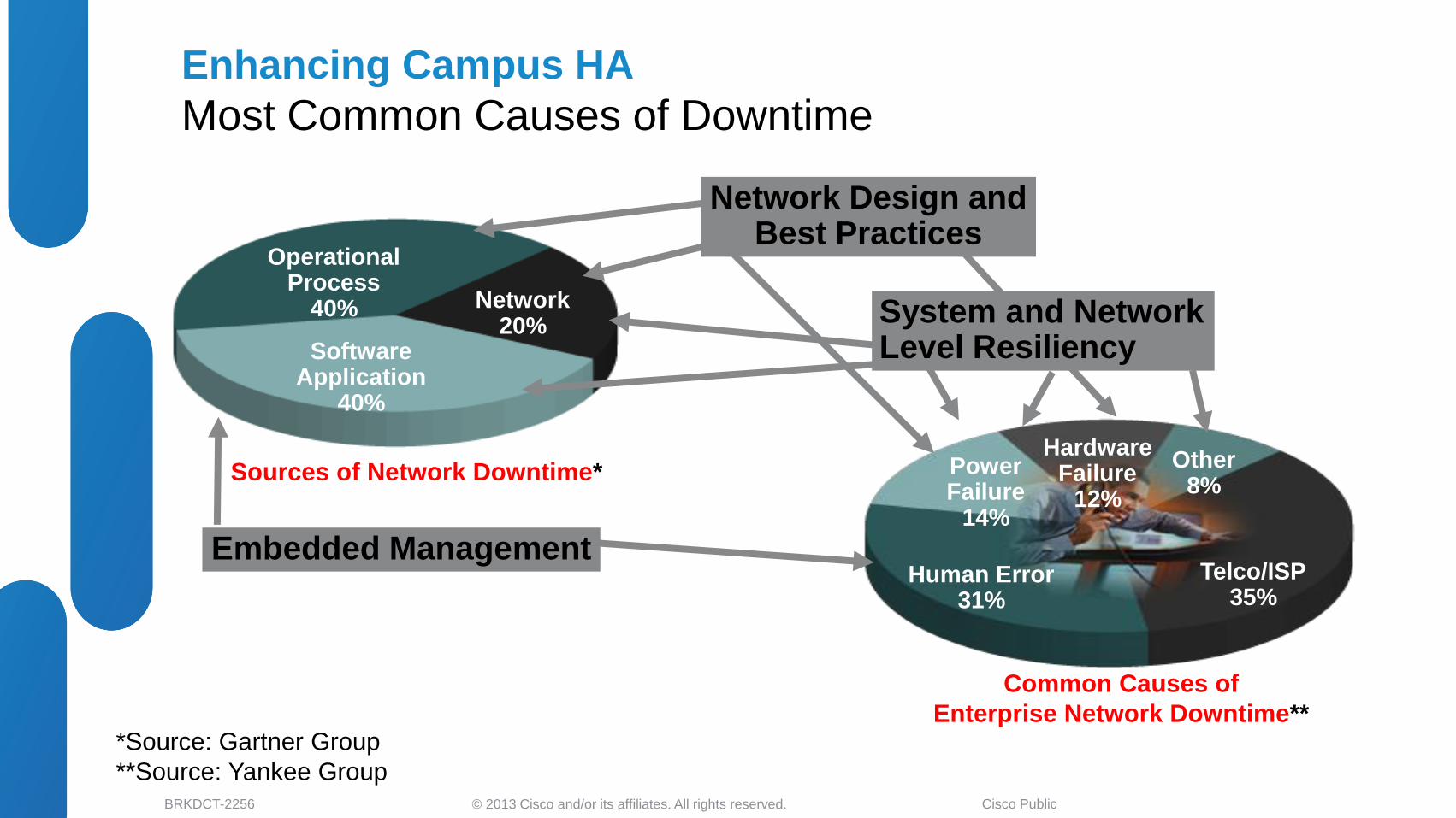
Enterprise Class Availability
Resilient Campus Communication Fabric
• VOIP availability is the baseline for
the enterprise networks
•Human ear notices the difference in
voice within 150–200 msec, which
translates only ten consecutive packet
loss with G711 codec
• Video loss is even more noticeable
and it is rapidly becoming new
frontier for jitter and delay
requirements
• 200 msec end-to-end campus
convergence is the design goal
Next-Generation Apps
Video Conf., Unified Messaging,
Global Outsourcing,
E-Business, Wireless Ubiquity
Mission-Critical Apps,
Databases, Order-Entry,
CRM, ERP
Desktop Apps
E-Mail, File, and Print
Ultimate Goal……………..100%
Applications Drive Requirements for High Availability Networking
Systems Design Approach to High Availability

© 2013 Cisco and/or its affiliates. All rights reserved. BRKDCT-2256 Cisco Public
Maximizes Bandwidth Utilization
•Maximize system usage •Maximize server usage •NIC standardization
Lowers Latency
•Optimized path selection • Increased throughput
SiSi SiSi
Cisco VSS Key Benefits
Design Guide: www.cisco.com/go/srnd http://www.cisco.com/en/US/docs/solutions/Enterprise/Campus/Borderless_Campus_Network_1.0/Borderless_Campus_1.0_Design_Guide.html http://www.cisco.com/en/US/docs/solutions/Enterprise/Campus/VSS30dg/campusVSS_DG.html
Simplifies Operational
Manageability
•Reduce 50% of Managed Nodes
•Loop-free topology •LMS 3.0 integration
Boosts Non-Stop Communications
•Deterministic sub-sec network recovery
•Business continuity with no service disruption
Supported Platforms
Catalyst 6500E
Catalyst 4500E
Catalyst 4500X

© 2013 Cisco and/or its affiliates. All rights reserved. BRKDCT-2256 Cisco Public
Data Center WAN Internet
VSS Enabled Campus Design End-to-End VSS Design Option
6
Data Center WAN Internet
SiSi SiSi SiSi SiSi
SiSiSiSi
SiSi SiSiSiSiSiSi
SiSi SiSi

© 2013 Cisco and/or its affiliates. All rights reserved. BRKDCT-2256 Cisco Public
Advance Virtual Switching System Design Agenda
7
• Cisco VSS Architecture
• VSS Architecture Overview
• Unified System Architecture
• Designing VSS System Redundancy
• VSS Dual and Quad-Sup Redundancy Design
• Virtual Switch Link Design and Best Practices
• Designing VSS Network Redundancy
• Multi-Chassis EtherChannel and ECMP Design
• Load Sharing and Resiliency
• Designing VSS Enabled Campus Network
• Access Layer
• Distribution and Core Layer – Design, Best Practices and Failure Analysis
• VSS Dual Active Detection
• Understanding Dual Active and Recovery Mechanics
• Dual Active Best Practices and Failure Analysis
• Summary

© 2013 Cisco and/or its affiliates. All rights reserved. BRKDCT-2256 Cisco Public
VSS-SW2 VSS-SW1
Cisco VSS Architecture Overview
8
Intra-Chassis SSO Redundancy
Catalyst 6500E/4500E
Line Card
Line Card
Active Sup
SF PFC RP
Internal EOBC
Standalone
External EOBC (VSL)
Line Card
Line Card
Internal EOBC
Standby Sup
SF PFC RP
Standby Sup
SF PFC RP
Inter-Chassis SSO Redundancy
Catalyst 6500E/4500E
SF : Switch Fabric PFC : Policy Feature Card
RP : Route Processor EOBC : Ethernet Out-of-Band Channel
Internal EOBC : Internal communication control channel between supervisor and linecards within single-chassis
External EOBC : External communication control channel between supervisors between two-chassis

© 2013 Cisco and/or its affiliates. All rights reserved. BRKDCT-2256 Cisco Public
Unified System Architecture
9
SF : Switch Fabric PFC : Policy Feature Card
RP : Route Processor EOBC : Ethernet Out-of-Band Channel
Simplified Control-Plane
Single Control-Plane to manage two
physical systems
Consistent IOS software feature
parity as Standalone
Centralized Programming for
distributed forwarding
Common Management
Single virtual system for OOB/In-Band
management of two physical systems
Common SNMP MIBs, Traps with
advance VSS MIBS
Single troubleshooting point
SW1
Line Card
Line Card
Line Card
Line Card
Line Card
Line Card
Line Card
Line Card
Standby Sup
Active Sup
VSS#show switch virtual redundancy
My Switch Id = 1
Peer Switch Id = 2
Switch 1 Slot 5 Processor Information :
-----------------------------------------------
Current Software state = ACTIVE
<snip>
Configuration register = 0x2
Fabric State = ACTIVE
Control Plane State = ACTIVE
Switch 2 Slot 5 Processor Information :
-----------------------------------------------
Current Software state = STANDBY HOT (switchover target)
<snip>
Configuration register = 0x2 Fabric State = ACTIVE
Control Plane State = STANDBY
VSL
VSS-SW2 VSS-SW1
Catalyst 6500E/4500E
Line Card
Line Card
Active Sup
SF PFC RP
Line Card
Line Card
Standby Sup
SF PFC RP
Catalyst 6500E/4500E

© 2013 Cisco and/or its affiliates. All rights reserved. BRKDCT-2256 Cisco Public
Unified Forwarding Architecture
10
SF : Switch Fabric PFC : Policy Feature Card
RP : Route Processor EOBC : Ethernet Out-of-Band Channel
Catalyst 4500E
• VSS Active Supervisor builds and maintain
network topologies
• Programs Forwarding Engine on both virtual
switch supervisor module
• Distributed Inter-Chassis Forwarding.
Centralized Intra-Chassis Forwarding design
Catalyst 4500E (Centralized Forwarding Architecture)
Catalyst 4500X (Centralized Forwarding Architecture)
Catalyst 6500E (Distributed Forwarding Architecture)
SW1
Line Card
Line Card
Line Card
Line Card
Line Card
Line Card
Line Card
Line Card
Standby Sup
Active Sup Layer 2 / 3
Network Standby Switch
Active Switch Layer 2 / 3
Network
SW1
SW1
Line Card
Line Card
Line Card
Line Card
Line Card
Line Card
Line Card
Line Card
Standby Sup
Active Sup Layer 2 / 3
Network
Catalyst 4500X
• Same Forwarding Architecture as
Catalyst 4500E
Catalyst 6500E
• Hybrid Forwarding Design –
Distributed/Centralized
• VSS Active supervisor builds and maintain
network topologies
• Distributed Inter + Intra-Chassis Forwarding
Centralized Intra-Chassis Forwarding

© 2013 Cisco and/or its affiliates. All rights reserved. BRKDCT-2256 Cisco Public
Advance Virtual Switching System Design Agenda
11
• Cisco VSS Architecture
• VSS Architecture Overview
• Unified System Architecture
• Designing VSS System Redundancy
• VSS Dual and Quad-Sup Redundancy Design
• Virtual Switch Link Design and Best Practices
• Designing VSS Network Redundancy
• Multi-Chassis EtherChannel and ECMP Design
• Load Sharing and Resiliency
• Designing VSS Enabled Campus Network
• Access Layer
• Distribution and Core Layer – Design, Best Practices and Failure Analysis
• VSS Dual Active Detection
• Understanding Dual Active and Recovery Mechanics
• Dual Active Best Practices and Failure Analysis
• Summary

© 2013 Cisco and/or its affiliates. All rights reserved. BRKDCT-2256 Cisco Public
Standby
VSS Dual-Sup Inter-Chassis Redundancy
• VSS Dual-Sup (single sup per chassis) supports inter-
chassis SSO redundancy.
• Single in-chassis supervisor - SSO Active or Standby
role.
• Stateful SSO synchronization and redundancy between
virtual-switches
• Single Sup System Design –
‒ Supervisor switchover requires chassis reset, including all
linecard and service modules
‒ Network capacity reduced until system returns to operational
state
• Consistent redundancy design between modular Catalyst
6500E/4500E and fixed Catalyst 4500X system
12
Reduced Capacity
Reduced Capacity
SiSi
Reduced Capacity
Reduced Capacity
NSF Recovery
Active Active Standby
VSL
© 2013 Cisco and/or its affiliates. All rights reserved. BRKDCT-2256 Cisco Public
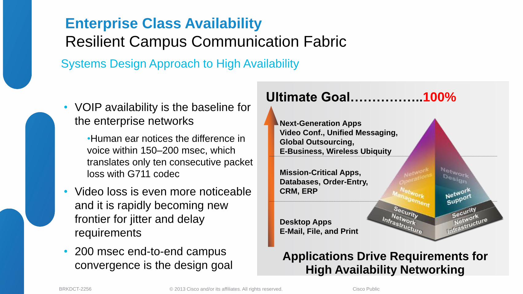
New Active Supervisor
Catalyst 6500E VSS Quad-Sup with RPR-WARM
• Starting 12.2(33)SXI4 Sup720-10GE VSS supports two sup
redundancy modes :
‒ Dual-Sup – One Sup per virtual-switch
‒ Quad-Sup – Two Sup’s per virtual-switch
• Dual Sup offers single redundancy option –
‒ Inter-Chassis only. Resetting Active or Standby supervisor reboots all
installed modules
‒ Sup hardware failure may increase MTTR, reduce network capacity,
services availability and may build un-reliable network
• Quad Sup offers dual redundancy options –
‒ Inter-Chassis – Same design as dual-sup
‒ Intra-Chassis – Allows virtual switch to return in-service, reduce MTTR and
stabilize network from major fault
13
SiSi
Self Recovery Fail
Single Point of Failure
Reduced Capacity
Reduced Capacity
NSF Recovery
Sup720-10GE Quad-Sup Redundancy
VSL

© 2013 Cisco and/or its affiliates. All rights reserved. BRKDCT-2256 Cisco Public
ICS – RPR-WARM ICS – RPR-WARM
VSS Quad Sup Supports Dual HA Mode
14
VSL
SiSiSiSiSiSi SiSiSiSiSiSi
Inter-Chassis Sup Redundancy
SW1 SW2
Intra-Chassis Sup Redundancy
Intra-Chassis Sup Redundancy
• Dual in-chassis supervisors, each in different redundancy modes –
In-chassis Active Supervisor (ICA) – In SSO Active OR Standby Mode
In-chassis Standby Supervisor (ICS) – RPR-WARM Mode
• Stateful SSO synchronization from SSO Active to Standby supervisor
• System configuration synchronization between ICA and ICS supervisors
• Chassis reset when ICA supervisor reset
ICA – SSO Active ICA – SSO Standby
Sup720-10GE Quad-Sup Redundancy

© 2013 Cisco and/or its affiliates. All rights reserved. BRKDCT-2256 Cisco Public
Catalyst 6500E Quad-Sup NSF/SSO Redundancy
15
Non-Stop Network Availability and Performance
ICS – STANDBY-HOT ( Chassis) ICS – STANDBY-HOT(Chassis)
VSL
SiSiSiSiSiSi SiSiSiSiSiSi
SW1 SW2
Intra-Chassis Sup Redundancy
Intra-Chassis Sup Redundancy
• Dual in-chassis Sup2T supervisors, each in different redundancy modes –
In-chassis Active Supervisor (ICA) – SSO Active OR Standby-Hot (switchover target)
In-chassis Standby Supervisor (ICS) – Standby-Hot (Chassis)
• VSS Quad-Sup protects network availability and capacity with dual redundancy domain
• Stateful SSO synchronization between multiple redundancy domains
• Complete system configuration and parameters synchronization between Quad supervisors
• Chassis and modules remains operational when Active or Standby-Hot supervisor resets
ICA – SSO Active ICA – SSO Standby
Inter-Chassis Sup Redundancy
Shipping in
March 2013
© 2013 Cisco and/or its affiliates. All rights reserved. BRKDCT-2256 Cisco Public
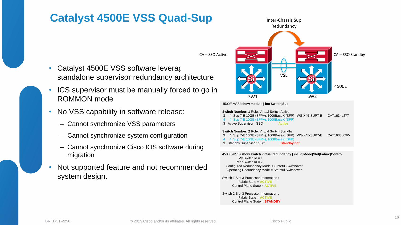
Catalyst 4500E VSS Quad-Sup
• Catalyst 4500E VSS software leverages existing
standalone supervisor redundancy architecture
• ICS supervisor must be manually forced to go in
ROMMON mode
• No VSS capability in software release:
‒ Cannot synchronize VSS parameters
‒ Cannot synchronize system configuration
‒ Cannot synchronize Cisco IOS software during
migration
• Not supported feature and not recommended
system design.
16
4500E
ICS – ROMMON ICS – ROMMON
VSL SiSiSiSiSiSi SiSiSiSiSiSi
Inter-Chassis Sup Redundancy
SW1 SW2
Intra-Chassis Sup Redundancy
Intra-Chassis Sup Redundancy
ICA – SSO Active ICA – SSO Standby
4500E-VSS#show module | inc Switch|Sup
Switch Number: 1 Role: Virtual Switch Active
3 4 Sup 7-E 10GE (SFP+), 1000BaseX (SFP) WS-X45-SUP7-E CAT1634L277
4 4 Sup 7-E 10GE (SFP+), 1000BaseX (SFP)
3 Active Supervisor SSO Active
Switch Number: 2 Role: Virtual Switch Standby
3 4 Sup 7-E 10GE (SFP+), 1000BaseX (SFP) WS-X45-SUP7-E CAT1633L09W
4 4 Sup 7-E 10GE (SFP+), 1000BaseX (SFP)
3 Standby Supervisor SSO Standby hot
4500E-VSS#show switch virtual redundancy | inc Id|Mode|Slot|Fabric|Control
My Switch Id = 1
Peer Switch Id = 2
Configured Redundancy Mode = Stateful Switchover
Operating Redundancy Mode = Stateful Switchover
Switch 1 Slot 3 Processor Information :
Fabric State = ACTIVE
Control Plane State = ACTIVE
Switch 2 Slot 3 Processor Information :
Fabric State = ACTIVE
Control Plane State = STANDBY

© 2013 Cisco and/or its affiliates. All rights reserved. BRKDCT-2256 Cisco Public
Standalone to VSS Conversion
17
• Step-1 : Configure VSS Domain ID
‒ Common Domain ID between two pairing systems
‒ Unique Domain ID network-wide. Duplicate ID may fail L2 protocols
‒ Range 1-255
SW1
• Step-2 : Configure Switch ID
‒ Unique Switch ID per switch in same VSS Domain
‒ Range 1-2
• Step-3 : Configure Switch Priority (Optional)
‒ Unique Switch Priority per switch in same VSS Domain
‒ Range 1-255. Default 100
• Step-5 : Configure VSL EtherChannel
‒ Unique Port-Channel per switch
‒ Up to 8 physical ports bundle in VSL EtherChannel
• Step-4 : Configure VSS Virtual MAC-Address
‒ Virtual MAC Address for reliable Layer 3
communication
System and Sup Redundancy Independent Process
SW1 SW2
SW1(config)#switch convert mode virtual SW2(config)#switch convert mode virtual
SW1 SW2
Step-1 SW1(config)#switch virtual domain 10 SW2(config)#switch virtual domain 10
Step-2 SW1(config-vs)#switch 1 SW2(config-vs)#switch 2
Step-3 SW1(config-vs)#switch priority 110 SW2(config-vs)#switch priority 100
Step-4 SW1(config-vs)#mac-address use-virtual SW2(config-vs)# mac-address use-virtual
Step-5 SW1(config)#interface Port-Channel 1
SW1(config-if)#switch virtual 1
!
SW1(config-if)#interface range Ten5/1 – 2
SW1(config-if-range)#channel-group 1
mode on
SW2(config)#interface Port-Channel 2
SW2(config-if)#switch virtual 1
!
SW2(config-if)#interface range Ten5/1 – 2
SW2(config-if-range)#channel-group 2
mode on
VSL
SW2
Po1 Po2
SW1
SiSiSiSiVSL

© 2013 Cisco and/or its affiliates. All rights reserved. BRKDCT-2256 Cisco Public
VSS Supervisor Redundancy Summary
Quad-Sup (SSO) Quad-Sup (RPR-WARM) Dual-Sup
Supported Platforms Catalyst 6500E – Sup2T Catalyst 6500E – Sup720-10GE Catalyst 6500E, 4500E and 4500X
Switch Fabric Inter-Chassis(ICA) – Active
Intra-Chassis (ICS) – Ready
Inter-Chassis (ICA) – Active
Intra-Chassis (ICS) – Inactive
Inter-Chassis – Active
Switching Capacity 4 Tbps 1.4 Tbps 4500E / 4500X – 1.6 Tbps
6500E Sup720-10GE – 1.4 Tbps
6500E Sup2T – 4 Tbps
Policy Feature Inter-Chassis(ICA) – Active
Intra-Chassis (ICS) – Inactive
Inter-Chassis (ICA) – Active
Intra-Chassis (ICS) – Inactive
Inter-Chassis – Active
BOOT, VLAN Dbase and
Startup config Sync
Inter-Chassis (ICS) + Intra-Chassis (ICA) Inter-Chassis (ICA) + Intra-Chassis (ICS) Inter-Chassis
Running configuration Inter-Chassis (ICA) Inter-Chassis (ICA) Inter-Chassis
SSO State Synchronization Inter-Chassis (ICA) Inter-Chassis (ICA) Inter-Chassis
eFSU Software Upgrade Inter-Chassis (ICA) + Intra-Chassis (ICS) Inter-Chassis (ICA) + Intra-Chassis (ICS) Inter-Chassis
18
Catalyst 4500E/4500X/6500E
Catalyst 6500E – Sup720-10GE Catalyst 6500E – Sup2T

© 2013 Cisco and/or its affiliates. All rights reserved. BRKDCT-2256 Cisco Public
Understanding Virtual Switch Link
• Inter-Chassis System Link
‒ No network protocol operations
‒ Invisible in network topology
‒ Transparent to network level troubleshooting
• VSL Control Link
‒ Carries all system internal control traffic
‒ Single member-link and dynamic election during
bootup
‒ Shared interface for network/data traffic
‒ < 50 msec switchover to pre-determined VSL path
• Payload Overhead
‒ Every single packet encapsulated with Virtual Switch
Header (VSH)
‒ Non-bridgeable and Non-routeable.
‒ VSL must be directly connected between two virtual
switch systems
19
Control Link Control Link
L3 Payload L2 CRC VSH
VSL
4500E-VSS#show switch virtual link Executing the command on VSS member switch role = VSS Active, id = 1 VSL Status : UP VSL Uptime : 1 day, 1 hour, 16 minutes VSL Control Link : Te1/3/1 Executing the command on VSS member switch role = VSS Standby, id = 2 VSL Status : UP VSL Uptime : 1 day, 1 hour, 17 minutes VSL Control Link : Te2/3/1

© 2013 Cisco and/or its affiliates. All rights reserved. BRKDCT-2256 Cisco Public
Virtual Switching System VSLP Framework
– Building Virtual System
Link Management Protocol (LMP)
• LMP protocol operates on each VSL member-link for peer-switch
detection, link integrity and bi-directionality health check
• Default hello and dead timers are non-tunable and are optimal for
various purpose. LMP hello timers (aka VSLP timers) :
Catalyst 6500E LMP Hello / Dead Timer = 0.5 sec / 60 sec
Catalyst 4500E/4500X LMP Hello / Dead Timer = 1 sec / 30 sec
• For older 6500E VSS deployments, it is strongly recommended
not to modify default LMP(VSLP) timer
Role Resolution Protocol (RRP)
• RRP runs on control link of the VSL bundle
• Determines whether software versions allow a virtual switch to
form
• Determines which chassis will become Active or Hot Standby from
a control plane perspective by checking configuration of switch
priority or pre-emption
• RRP roles are negotiated when either of the switch member
initializes or when VSL link is restored
20
LMP LMP
RRP RRP
6500-VSS#show vslp lmp timer LMP hello timer Hello Tx (T4) Hello Rx (T5*) ms Interface State Cfg Cur Rem Cfg Cur Rem --------------------------------------------------------------------------------------------- Te2/5/4 operational - 500 156 - 60000 59952 Te2/2/8 operational - 500 156 - 60000 59952
6500-VSS#show switch virtual role Switch Switch Status Preempt Priority Role Session ID
Number Oper(Conf) Oper(Conf) Local Remote ----------------------------------------------------------------------------------------------------------------------------------- LOCAL 1 UP FALSE(N) 110(110) ACTIVE 0 0
REMOTE 2 UP FALSE(N) 100(100) STANDBY 9924 7656
4500-VSS#show vslp lmp timer LMP hello timer Hello Tx (T4) ms Hello Rx (T5*) ms Interface State Cfg Cur Rem Cfg Cur Rem --------------------------------------------------------------------------------------------- Te1/3/1 operational - 1000 700 - 30000 29416 Te1/4/1 operational - 1000 472 - 30000 29692
VSL

© 2013 Cisco and/or its affiliates. All rights reserved. BRKDCT-2256 Cisco Public
6500E VSS Dual Sup – VSL Design
21
Two Cisco recommended designs
Sup2T and Sup720-10GE Design
VSL
Sup Sup
Profile 1 – VSL on Supervisor (Sup2T/Sup720-10GE)
• Cost-effective solution to leverage both uplinks. Continue to use
non-VSL capable linecard for 10G core connection.
• Redundant fibers connects thru common fabric and ASICs, this
could result vulnerability in system stability.
• Optimal and preset VSL parameters – Load-Balancing, QoS, HA,
Traffic-engg, Dual-Active etc.
• Restricted to bundle 2 x VSL ports or 20G switching capacity on
per virtual-switch node basis.
VSL
Sup Sup
Profile 2 – Diversified VSL between Supervisor (Sup2T/Sup720-10GE) and VSL capable Linecard
• Redundant and diversified fibers between supervisor and next-gen
VSL capable linecards.
• Same design as Profile 1 but increases system reliability as each
VSL port are diversified across different fabric/ASICs.
• Optimal and preset VSL parameters – Load-Balancing, QoS, HA,
Traffic-engg, Dual-Active etc.
• Flexible to scale up to 8 x VSL for high-dense system to aggregate
uplink, service modules, single-home etc.

© 2013 Cisco and/or its affiliates. All rights reserved. BRKDCT-2256 Cisco Public
Sup-3 Sup-4
VSL
SW1 SW2
Sup-1 Sup-2
SiSiSiSiSiSi
Sup-3 Sup-4
• Same Design Profile – 1 Dual Sup
• Flexible to increase VSL Capacity
• Continue to leverage existing non-VSL 10G
linecard for uplink connection
• Retains all original VSL benefits
• Vulnerable design during any supervisor self-
recovery fault incident
Recommended Full-Mesh VSL on Quad-Sup
SiSiSiSiSiSi
Sup-3 Sup-4
VSL
SW1 SW2
Sup-1 Sup-2
Sup-3 Sup-4
• Highly Redundant and cost-effective VSL
Design.
• Increases overall VSL Capacity
• Maintains 20G VSL Capacity during
supervisor failure.
• Increases network reliability by minimizing the
dual-active probability
6500E VSS VSL Design – Quad-Sup (SSO / RPR-WARM) Sup2T Quad-Sup NSF/SSO VSL Redundancy
22
SiSiSiSiSiSi SiSiSiSiSiSi

© 2013 Cisco and/or its affiliates. All rights reserved. BRKDCT-2256 Cisco Public 23
4500E VSS Dual-Sup – VSL Network Design
Two Cisco recommended designs
Profile 1 – VSL on Sup7-E
• Cost-effective solution to leverage Quad uplinks for VSL and
Core connections
• For reliable internal connection diversify fibers between
Uplink ports groups thru different fabric and ASICs
connection
• Optimal and preset VSL parameters – Load-Balancing, QoS,
HA, Traffic-engg, Dual-Active etc.
• Restricted to bundle 2 x VSL ports or 20G switching capacity
on per virtual-switch node basis.
VSL
Sup Sup
VSL
Sup Sup
Profile 2 – Diversified VSL between Supervisor (Sup7-E/Sup7-LE) and VSL capable Linecard
• Redundant and diversified fibers between supervisor and VSL
capable linecards.
• Same design as Profile 1 but increases system reliability as each
VSL port are diversified across different ASICs.
• Optimal and preset VSL parameters – Load-Balancing, QoS, HA,
Traffic-engg, Dual-Active etc.
• Flexible to scale up to 8 x VSL for high-dense system to aggregate
uplink, service modules, single-home etc.
Sup7E and Sup7-LE Design

© 2013 Cisco and/or its affiliates. All rights reserved. BRKDCT-2256 Cisco Public
Catalyst 4500E Sup7LE – VSL Uplink Select Best Practices
24
• 4500E – Sup7LE supervisor module supports following
uplink interfaces :
2 Port 10G Uplink (Default)
4 Port 1G Uplink
• The default 10G uplink ports can be modified to 1G
using “hw-module uplink select gigabit” CLI
• Prior rebooting the existing VSL port configuration must
be manually copied to new ports to successfully make
new configuration effective
• VSS switches may enter in dual active and de-stabilize
the network if configuration not copied correctly
SW-1 SW-2
VSL
Step Task
Step-1 Connect cables to new VSL uplink ports
Step-2 Copy all current VSL member-link configuration to new
VSL uplink member-links ports
Step-3 Modify uplink port configuration using “hw-module uplink
select (gigabit | tengig)” CLI in global exec mode
Step-4 Save configuration and reload both systems using
“redundancy reload shelf” CLI

© 2013 Cisco and/or its affiliates. All rights reserved. BRKDCT-2256 Cisco Public
Fixed switch hardware architecture –
24 or 48 10G/1G Front Panel Ports
8 port 1G/10G Pluggable Uplink Module
Any ports can be bundled into VSL EtherChannel.
Recommended to use front-panel ports to build VSL
connections. Minimizes system instability during accidental
uplink module OIR/reset
Recommended to use odd or even front-panel port numbers.
Splits VSL member-link interfaces to different internal ASICs.
Consistent software design and VSL function as 4500E
Front Panel Ports
SiSiSiSiSiSiSiSiSiSiSiSi
Front / Uplink Ports
SW-1 SW-2
4500-X 4500-X
4500X VSS – VSL Network Design
25
VSL
Ten1/1/1
Ten1/1/5
Ten2/1/1
Ten2/1/5

© 2013 Cisco and/or its affiliates. All rights reserved. BRKDCT-2256 Cisco Public
Understanding VSL Forwarding Design
26
• The VSL control and data plane software design is
intelligent and optimal
Builds neighbor adjacencies and maintains system virtualization
thru remote chassis physical port connection
Develops distributed hardware forwarding design and use VSL as
“last-resort” interface
• VSL carries following traffic categories:
System Control Traffic – VSS Control protocols, i.e. LMP, IPC, SCP etc
Network Control Traffic – Per-Port L2/L3 protocols, i.e. PAgP, CDP,
EIGRP/OSPF etc
User Data Plane – Single Homed Devices traffic
Services Traffic – Integrated Services Module, SPAN etc
• Common EtherChannel load sharing and hash mechanics
for control and data traffic
SW-1 SW-2
VSL
6500-vss#show int vsl
VSL Port-channel: Po1
Port: Te1/5/4
Port: Te1/5/5
VSL Port-channel: Po2
Port: Te2/5/4
Port: Te2/5/5
6500-vss#show vsl lmp neighbor
Instance #1:
LMP neighbors
Peer Group info: # Groups: 1 (* => Preferred PG)
PG # MAC Switch Ctrl Interface Interfaces
--------------------------------------------------------------------------------------------
*1 001a.30e1.6800 2 Te1/5/4 Te1/5/4, Te1/5/5
6500-vss#remote command switch-id 2 mod 5 show vsl lmp neighbor
Instance #2:
LMP neighbors
Peer Group info: # Groups: 1 (* => Preferred PG)
PG # MAC Switch Ctrl Interface Interfaces
-------------------------------------------------------------------------------------------
*1 001a.30f1.e800 1 Te2/5/4 Te2/5/4, Te2/5/5
© 2013 Cisco and/or its affiliates. All rights reserved. BRKDCT-2256 Cisco Public
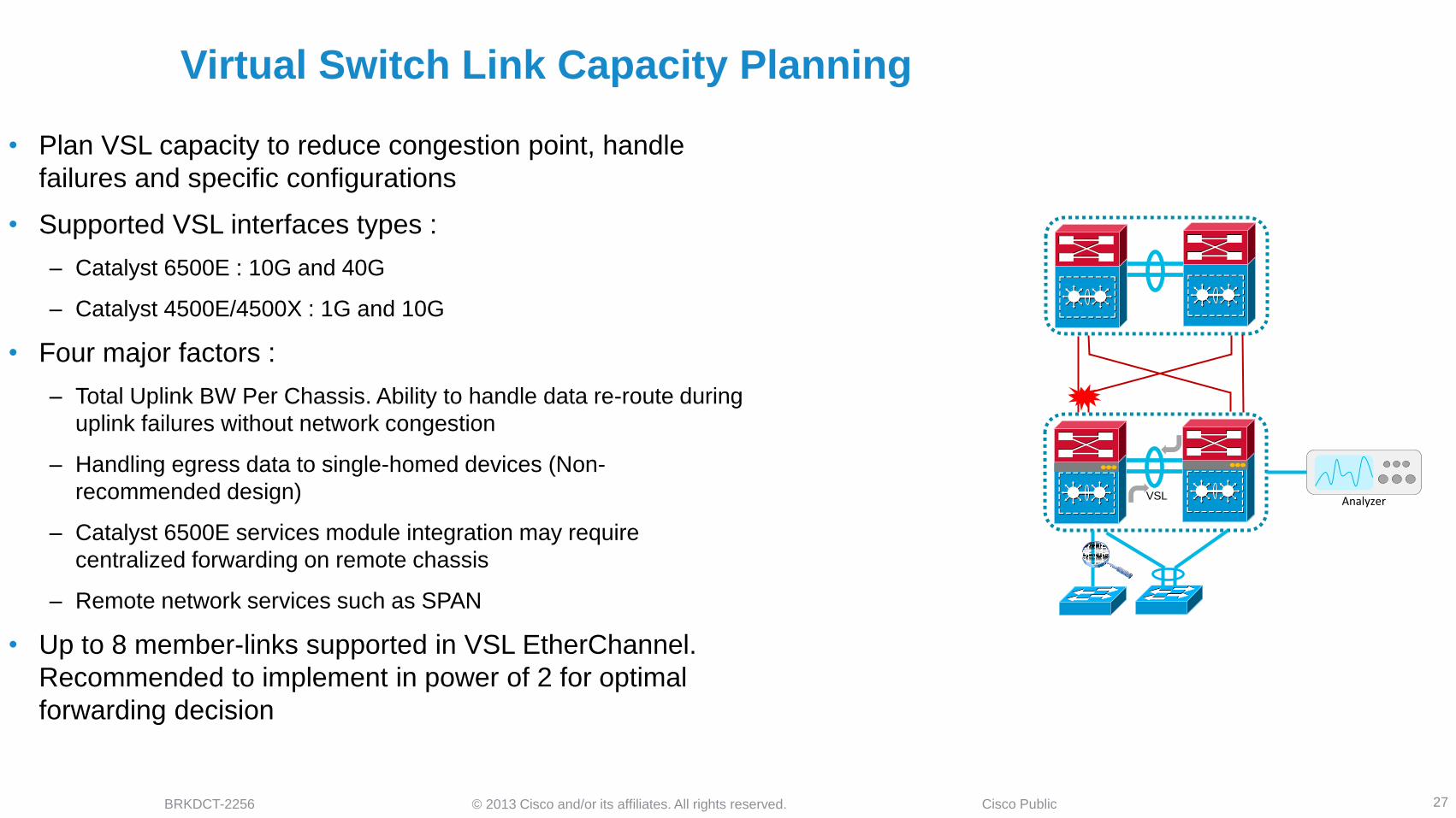
Virtual Switch Link Capacity Planning
27
• Plan VSL capacity to reduce congestion point, handle
failures and specific configurations
• Supported VSL interfaces types :
‒ Catalyst 6500E : 10G and 40G
‒ Catalyst 4500E/4500X : 1G and 10G
• Four major factors :
‒ Total Uplink BW Per Chassis. Ability to handle data re-route during
uplink failures without network congestion
‒ Handling egress data to single-homed devices (Non-
recommended design)
‒ Catalyst 6500E services module integration may require
centralized forwarding on remote chassis
‒ Remote network services such as SPAN
• Up to 8 member-links supported in VSL EtherChannel.
Recommended to implement in power of 2 for optimal
forwarding decision
Analyzer VSL

© 2013 Cisco and/or its affiliates. All rights reserved. BRKDCT-2256 Cisco Public
Advance Virtual Switching System Design Agenda
Cisco VSS Architecture
VSS Architecture Overview
Unified System Architecture
Designing VSS System Redundancy
VSS Dual and Quad-Sup Redundancy Design
Virtual Switch Link Design and Best Practices
Designing VSS Network Redundancy
Multi-Chassis EtherChannel and ECMP Design
Load Sharing and Resiliency
Designing VSS Enabled Campus Network
Access Layer
Distribution and Core Layer – Design, Best Practices and Failure Analysis
VSS Dual Active Detection
Understanding Dual Active and Recovery Mechanics
Dual Active Best Practices and Failure Analysis
Summary 28
© 2013 Cisco and/or its affiliates. All rights reserved. BRKDCT-2256 Cisco Public
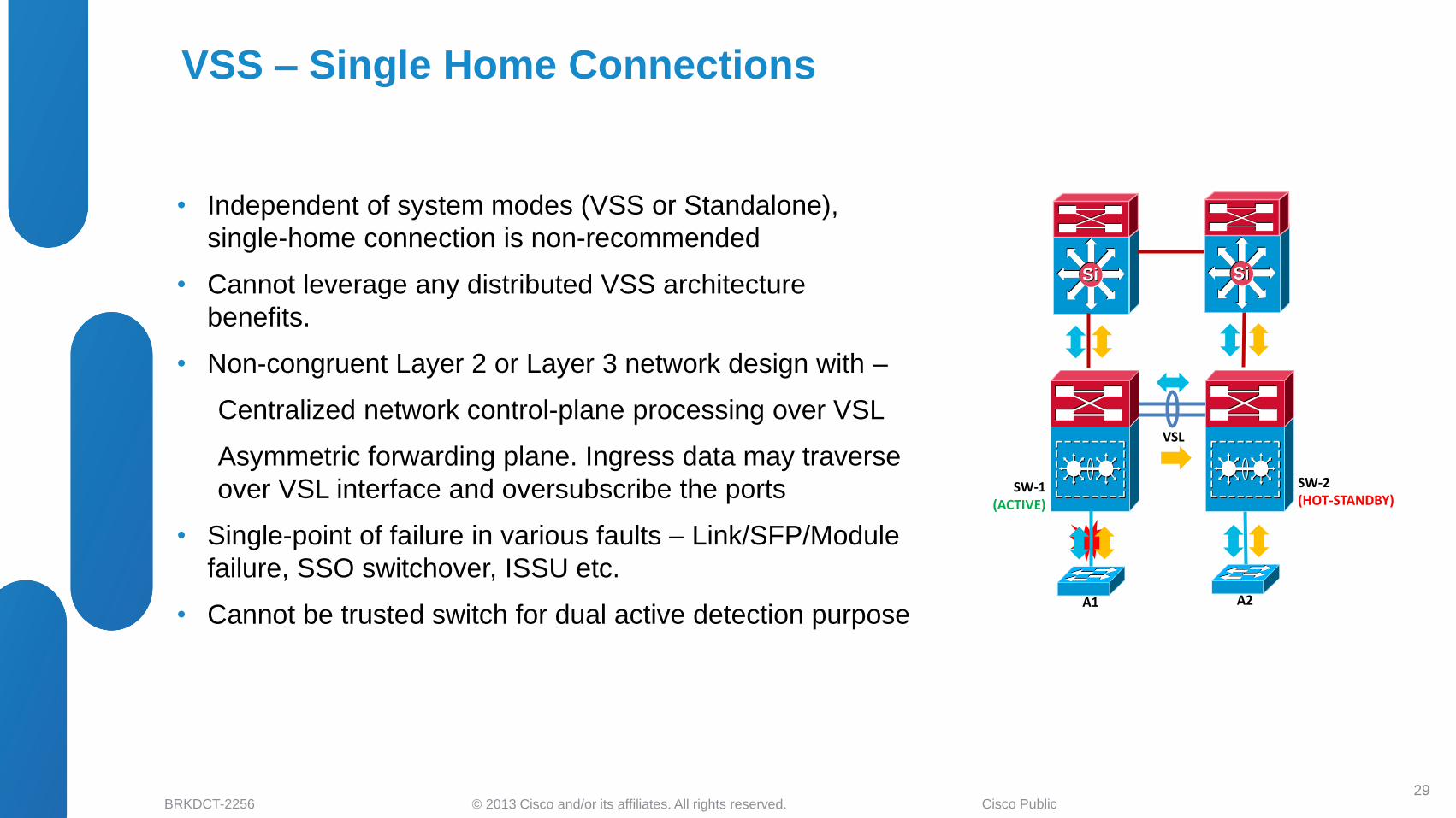
VSS – Single Home Connections
• Independent of system modes (VSS or Standalone),
single-home connection is non-recommended
• Cannot leverage any distributed VSS architecture
benefits.
• Non-congruent Layer 2 or Layer 3 network design with –
Centralized network control-plane processing over VSL
Asymmetric forwarding plane. Ingress data may traverse
over VSL interface and oversubscribe the ports
• Single-point of failure in various faults – Link/SFP/Module
failure, SSO switchover, ISSU etc.
• Cannot be trusted switch for dual active detection purpose
29
SW-1 (ACTIVE)
SW-2 (HOT-STANDBY)
VSL
A2
SiSiSiSiSiSi SiSiSiSiSiSi
A1
Single Point
Of Failure
© 2013 Cisco and/or its affiliates. All rights reserved. BRKDCT-2256 Cisco Public
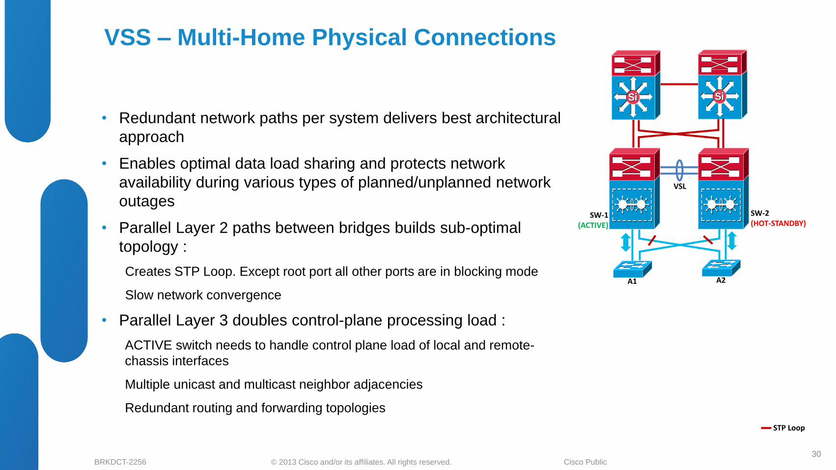
VSS – Multi-Home Physical Connections
• Redundant network paths per system delivers best architectural
approach
• Enables optimal data load sharing and protects network
availability during various types of planned/unplanned network
outages
• Parallel Layer 2 paths between bridges builds sub-optimal
topology :
Creates STP Loop. Except root port all other ports are in blocking mode
Slow network convergence
• Parallel Layer 3 doubles control-plane processing load :
ACTIVE switch needs to handle control plane load of local and remote-
chassis interfaces
Multiple unicast and multicast neighbor adjacencies
Redundant routing and forwarding topologies
30
SW-1 (ACTIVE)
SW-2 (HOT-STANDBY)
VSL
A2
SiSiSiSiSiSi
A1
SiSiSiSiSiSi
STP Loop

© 2013 Cisco and/or its affiliates. All rights reserved. BRKDCT-2256 Cisco Public
VSS – Multi-Chassis EtherChannel
• Multi-Chassis EtherChannel (MEC) in VSS enables distributed
link bundling into single logical L2/L3 Interface
• Combining VSS with MEC builds simplified, scalable and
highly resilient campus network
• MEC is an imperative network design component to enable –
Simplified STP loop-free network topology
Consistent L3 control-plane and network design as traditional
Standalone mode system
Deterministic sub-second network recovery
• MECs can be deployed in two modes –
Layer 2 = Supported on 6500E, 4500E and 4500X
Layer 3 = Supported on 6500E *
• MEC scalability support varies on system basis –
Catalyst 6500E supports 512 L2/L3 MEC
Catalyst 4500E and 4500X supports 256 L2 MEC
* L3 MEC is in 4500E/4500X roadmap 31
SW-1 (ACTIVE)
SW-2 (HOT-STANDBY)
VSL
A2
SiSiSiSiSiSi
A1
SiSiSiSiSiSi

© 2013 Cisco and/or its affiliates. All rights reserved. BRKDCT-2256 Cisco Public
8 4
Understanding MEC Load Sharing
• MEC hash algorithm is computed independently by each virtual-switch to perform load share via its local physical ports.
• 8 bits computation on each member link of an MEC is independently done on per virtual-switch node basis.
• Total number of member link bundling in single MEC recommendation remains consistent as described in single chassis Etherchannel section.
• Recommended to deploy EtherChannel in ratio of n2 that are evenly distributed to each virtual-switch for best load-sharing result.
32
Per Switch MEC Flow Distribution Matrix
Member Links
Port1 Bit
Port2 Bit
Port3 Bit
Port4 Bit
Port5 Bit
Port6 Bit
Port7 Bit
Port8 Bit
1 8 X X X X X X X
2 4 4 X X X X X X
3 3 3 2 X X X X X
4 2 2 2 2 X X X X
5 2 2 2 1 1 X X X
6 2 2 1 1 1 1 X X
7 2 1 1 1 1 1 1 X
8 1 1 1 1 1 1 1 1
Recommended MEC Bundle link configuration
8 4 4 4
SiSiVSL
SiSi
8
SiSi
SW-1 SW-2

© 2013 Cisco and/or its affiliates. All rights reserved. BRKDCT-2256 Cisco Public
Optimize EtherChannel Load Balancing
• Load share egress data traffic based on input hash
• Optimal load sharing results with :
Bucket-based load-sharing – Bundle member-links in power-of-2 (2/4/8)
Multiple variation of input for hash (L2 to L4)
• Recommended algorithm * :
Access – Src/Dst IP
6500E Dist/Core – Src/Dst IP + Src/Dst L4 Ports
4500E / 4500X Dist – Src/Dst IP
33
SiSi
Default : src-mac
Recommended : src-dst-ip
* May vary based on your network traffic pattern
Access
Default : src-dst-ip vlan
Recommended : src-dst-mixed-ip-port vlan Dist
Default : src-dst-ip vlan
Recommended : src-dst-mixed-ip-port
Core

© 2013 Cisco and/or its affiliates. All rights reserved. BRKDCT-2256 Cisco Public
6500E VSS – MEC EtherChannel Hash Algorithm
34
• Cat6500 in VSS or in non-VSS configuration mode has common support of EtherChannel Hash algorithms.
• 6500E EtherChannel Hash result computation mode:
Fixed – Recomputes hash results and programs each time when member-link flaps. May impact network convergence time. This is default mode and can be kept default if each virtual-switch node has single physical port bundled in same L2/L3 MEC.
Adaptive – Pre-computes hash results and programs member-link ports. Do not recompute when member-link flaps and improves network convergence. Best practice to modify to adaptive hash method only if each virtual-switch has >=2 physical port in same L2/L3 MEC.
• Unlike EtherChannel load sharing, the EtherChannel Hash can be globally enabled for entire system or it can be on per MEC basis. Modifying EtherChannel Hash algorithm requires manually EtherChannel reset to make effective.
6500-vss#show etherchannel 10 detail | inc Hash
Last applied Hash Distribution Algorithm: Fixed
6500-vss#show interface po10 etherchannel | inc Load|Gi
Index Load Port EC state No of bits
0 FF Gi1/4/1 Desirable-Sl 8
2 FF Gi2/4/1 Desirable-Sl 8
6500-vss#show etherchannel 10 detail | inc Hash
Last applied Hash Distribution Algorithm: Fixed
6500-vss#conf t
6500-vss(config)#port-channel hash-distribution adaptive
6500-vss(config)#do show etherchannel 10 detail | inc Hash
Last applied Hash Distribution Algorithm: Fixed
6500-vss(config)#interface port-channel <id>
6500-vss(config-if)#shutdown
6500-vss(config-if)#no shutdown
6500-vss#show etherchannel 10 detail | inc Hash
Last applied Hash Distribution Algorithm: Adaptive

© 2013 Cisco and/or its affiliates. All rights reserved. BRKDCT-2256 Cisco Public
Layer 3 Load Balancing Can Be Randomized with a Unique ID
Associated with Switch
35
• “Universal ID” concept (also called Unique ID) is used to prevent CEF polarization
Universal ID generated at bootup (32-bit pseudo-random value seeded by router’s base IP address)
• Universal ID used as input to ECMP hash, introduces variability of hash result at each network layer
• Universal ID supported on Catalyst 6500 Sup-720-10GE and Sup2T
• Universal ID supported on Catalyst 4500E – Sup7E, Sup7LE and Catalyst 4500X
Hash using
Source IP (SIP),
Destination IP (DIP)
&Universal ID
Original Src IP + Dst IP
Universal* Src IP + Dst IP + Unique ID
Include Port Src IP + Dst IP + (Src or Dst Port) + Unique ID
Default* Src IP + Dst IP + Unique ID
Full Src IP + Dst IP + Src Port + Dst Port
Full Exclude Port Src IP + Dst IP + (Src or Dst Port)
Simple Src IP + Dst IP
Full Simple Src IP + Dst IP + Src Port + Dst Port
Catalyst 4500E/4500X Load-Sharing Options Catalyst 6500 PFC3** Load-Sharing Options
* = default load-sharing mode
SiSi SiSi
SiSi SiSi
SiSi

© 2013 Cisco and/or its affiliates. All rights reserved. BRKDCT-2256 Cisco Public
Cisco PAgP and IETF LACP Best Practices
36
• Link bundling protocols builds reliable logical network connections between
two systems
• Cisco PAgP and IETF LACP protocol provides consistent solution –
Ensure link aggregation parameters consistency and compatibility between the
VSS and neighbor switch.
Ensure interface compliance with various aggregation requirements.
Dynamically react to runtime changes and failures on local and remote
Etherchannel systems
Detect and remove unidirectional links and multidrop connections from the
Etherchannel bundle
• Cisco PAgP MEC can be use for in-direct dual-active detection
• Recommended to implement in following modes for Layer 2 or Layer 3
EtherChannel :
Cisco PAgP = Desirable / Desirable on both MEC end
IETF LACP = Active / Active on both MEC end
Keep PAgP and LACP timers to default settings
• Implement non-negotiable EtherChannel mode (ON) only when remote
device do not support PAgP or LACP protocols, i.e. multi-home PC
interface TenG1/1/1 , TenG2/1/1
channel-protocol pagp
channel-group <id> mode desirable
interface TenG1/2/1 , TenG2/2/1
channel-protocol lacp
channel-group <id> mode active
SiSiSiSiSiSi
SiSi
PAgP Layer 2
Port-Channel
Catalyst 2K/3K/4K
SiSi
LACP Layer 3
Port-Channel
SiSiSiSiSiSi
VSL
SW1 SW2
4500E-VSS#show pagp neighbor Flags: S - Device is sending Slow hello. C - Device is in Consistent state. A - Device is in Auto mode. P - Device learns on physical port. Channel group 101 neighbors Partner Partner Partner PartnerGroup Port Name Device ID Port Age Flags Cap. Gi1/2/4 M09-3750-3 6073.5c8c.a780 Gi1/1/1 17s SC 10001 Gi2/2/4 M09-3750-3 6073.5c8c.a780 Gi1/1/2 4s SC 10001

© 2013 Cisco and/or its affiliates. All rights reserved. BRKDCT-2256 Cisco Public
LACP Secondary Aggregator Interface
37
• During EtherChannel bundling process, LACP performs configuration check between
physical bundle ports and port-channel and takes 2 following sequential actions :
If configuration check pass, both end system establishes control and forwarding-plane
information on user-defined port-channel group and both system function normally.
If configuration check fails than it automatically generate an EtherChannel interface with
unique alphabetical ID on each end device of an EtherChannel.
• System generated LACP MEC will bundle all the physical ports into an MEC that
failed configuration check. All control, forwarding and management-plane will be
independently operated over system generated LACP MEC.
• Such type of EtherChannel configuration mis-match condition will trigger dual
individual layer 2 EtherChannel paths between access and virtual-switch nodes. STP
topology will consider such network as a loop and block high STP port priority.
• Recommendation keep member-link configuration consistent to minimize network
impact
Active Standby
VSL
Po20
Gi2/1 Gi2/2
Switch#show etherchannel 20 summary | inc Gi 20Po20(SU) LACP Gi2/1(P) Gi2/2(P) Switch#show spanning-tree | inc Po20 Po20 Root FWD 3 128.1667 P2p Switch(config)#int gi2/2 Switch(config-if)#switchport nonegotiate Switch(config-if)#shut Switch(config-if)#no shut %EC-SPSTBY-5-CANNOT_BUNDLE_LACP: Gi2/2 is not compatible with aggregators in channel 20 and cannot attach to them (trunk mode of Gi2/2 is trunk, Gi2/1 is dynamic) %EC-SP-5-BUNDLE: Interface Gi2/2 joined port-channel Po20B
Switch#show etherchannel 20 summary | inc Gi 20Po20(SU) LACP Gi2/1(P) 21Po20B(SU) LACP Gi2/2(P) 6500-access#show spanning-tree | inc Po20 Po20 Root FWD 4 128.1667 P2p Po20B Altn BLK 4 128.1668 P2p
MEC config check fail
STP Block port Po20B
Po20A
SW-1 SW-2

© 2013 Cisco and/or its affiliates. All rights reserved. BRKDCT-2256 Cisco Public
Protocol Comparison – PAgP vs LACP
38
PAgP LACP
Standards Cisco Port-Aggregation Protocol IEEE 802.1ad Port-Aggregation Protocol
Interoperability PAgP capable Cisco platforms With LACP capable Cisco and third-party vendor device.
Max. ports in bundle 8 ports 8 ports
Additional port remains in HOT-STANDBY mode
Multicast MAC 01-80-c00-00-00 01-80-c00-00-02
Hello/Hold Timer Slow Rate – 30 sec / 105 sec
Fast Rate – 1 sec / 3 sec
Slow Rate – 30 sec / 105 sec
Fast Rate – 1 sec / 3 sec
Dual ACTIVE Detection Capable Yes No
Per Port operation Yes Yes
Local MEC inconsistency check Yes No. May create LACP Secondary Aggregator and STP loop with VSS
Uni-directional Link Detection Capability Yes Yes
Traffic Load-sharing Mechanism Link-aggregation Protocol independent with up to different 16 permutation traffic load-share across each bundle port in an PAgP or LACP enabled EtherChannel
Hello Timer Operational Symmetric Symmetric or Asymmetric
© 2013 Cisco and/or its affiliates. All rights reserved. BRKDCT-2256 Cisco Public
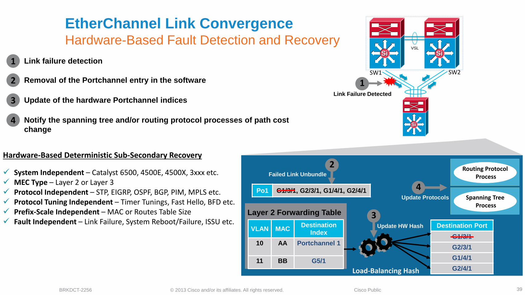
EtherChannel Link Convergence Hardware-Based Fault Detection and Recovery
39
Link failure detection
Removal of the Portchannel entry in the software
Update of the hardware Portchannel indices
1 Link Failure Detected
2
1
2
3
3
Routing Protocol Process
Spanning Tree Process
Notify the spanning tree and/or routing protocol processes of path cost
change
4
4
Layer 2 Forwarding Table
Load-Balancing Hash
Destination Port
G1/3/1
G2/3/1
G1/4/1
G2/4/1
VLAN MAC Destination
Index
10 AA Portchannel 1
11 BB G5/1
Po1 G1/3/1, G2/3/1, G1/4/1, G2/4/1
Hardware-Based Deterministic Sub-Secondary Recovery
System Independent – Catalyst 6500, 4500E, 4500X, 3xxx etc. MEC Type – Layer 2 or Layer 3 Protocol Independent – STP, EIGRP, OSPF, BGP, PIM, MPLS etc. Protocol Tuning Independent – Timer Tunings, Fast Hello, BFD etc. Prefix-Scale Independent – MAC or Routes Table Size Fault Independent – Link Failure, System Reboot/Failure, ISSU etc.
SiSi
SiSiSiSi
Failed Link Unbundle
Update HW Hash
Update Protocols
SW1 SW2
VSL

© 2013 Cisco and/or its affiliates. All rights reserved. BRKDCT-2256 Cisco Public
Cisco VSS System Design Summary
40
Catalyst 6500E Catalyst 4500E Catalyst 4500X
Network Layer Design Distribution and Core Distribution Distribution
Network Scale Large Mid/Small/Collapsed Mid/Small/Collapsed
Sup Redundancy Dual-Sup (Inter-Chassis)
Quad-Sup (NSF/SSO and RPR-WARM)
Dual-Sup
(Inter-Chassis)
Dual-Sup
(Inter-Chassis)
Network Design Alternatives ECMP and MEC (L2/L3) ECMP and MEC (L2) * ECMP and MEC (L2) *
Inter-Chassis Forwarding Distributed Distributed Distributed
Policy Features Design Distributed Distributed Distributed
Software Upgrade eFSU
(Dual and Quad-Sup)
ISSU
(Dual-Sup)
ISSU
(Dual-Sup)
* = Layer 3 MEC is in roadmap

© 2013 Cisco and/or its affiliates. All rights reserved. BRKDCT-2256 Cisco Public
Advance Virtual Switching System Design Agenda
41
Cisco VSS Architecture
VSS Architecture Overview
Unified System Architecture
Designing VSS System Redundancy
VSS Dual and Quad-Sup Redundancy Design
Virtual Switch Link Design and Best Practices
Designing VSS Network Redundancy
Multi-Chassis EtherChannel and ECMP Design
Load Sharing and Resiliency
Designing VSS Enabled Campus Network
Access Layer
Distribution and Core Layer – Design, Best Practices and Failure Analysis
VSS Dual Active Detection
Understanding Dual Active and Recovery Mechanics
Dual Active Best Practices and Failure Analysis
Summary

© 2013 Cisco and/or its affiliates. All rights reserved. BRKDCT-2256 Cisco Public
4500E
SW1
VSS in Access Layer – Key Benefits
42
• Single Management Plane to manage up to 768 end points
and ports with Catalyst 4500E switch
• Unified Control Plane to two large modular 4500E switches
• Distributed rich access-layer network technologies:
Power over Ethernet (PoE)
Quality of Service
Security ACLs, Identity etc
Flexible NetFlow
• Scalable Forwarding Architecture to deliver 1.696 Tbps
Access Layer
SiSiSiSiSiSi SiSiSiSiSiSi
SW1 SW2

© 2013 Cisco and/or its affiliates. All rights reserved. BRKDCT-2256 Cisco Public 43
• No protocol or topological difference between Standalone
and VSS modes
• Asymmetric downstream data plane forwarding design.
Heavy traffic over VSL as most end points are single-homed
connections
• Depending on distribution layer design the upstream traffic
may also traverse over VSL in certain condition
• Cannot leverage any distributed VSS architecture benefits.
VSS in Access Layer – Asymmetric Forwarding
SW-1 (ACTIVE)
SW-2 (HOT-STANDBY)
VSL
SiSiSiSiSiSi SiSiSiSiSiSi
Access Layer
Distribution Layer

© 2013 Cisco and/or its affiliates. All rights reserved. BRKDCT-2256 Cisco Public
Access Layer – VSS Mode
VSS in Access Layer – System Redundancy Challenge
44
• System level redundancy in access is base requirement
for single-home endpoints
• Standalone access design delivers non-disruptive
network communication with supervisor redundancy
• VSS require Quad-sup NSF/SSO software to deliver
equal redundancy.
• Dual sup VSS design have similar impact as single-sup
Standalone access switch
SW1 SW2 SW1
SiSiSiSiSiSi SiSiSiSiSiSi
SiSiSiSiSiSi SiSiSiSiSiSi
VSL
SiSiSiSiSiSi SiSiSiSiSiSi
SiSiSiSiSiSi SiSiSiSiSiSi
Access Layer – Standalone Mode

© 2013 Cisco and/or its affiliates. All rights reserved. BRKDCT-2256 Cisco Public
Distribution Layer Design Alternatives – Standalone vs VSS
45
• Traditional Distribution Block Design
• Dual Standalone System
• Distributed Planes
• Protocol dependent fault detection and
recovery
• Evolution Network Design
• Single Virtual System
• Unified Control and Management
plane. Distributed Forwarding plane.
• Deterministic Network Recovery.
Vlan 10 Vlan 20 Vlan 30
SiSi SiSiSiSi SiSi
Vlan 10 Vlan 20 Vlan 30

© 2013 Cisco and/or its affiliates. All rights reserved. BRKDCT-2256 Cisco Public
Traditional Distribution Design
46
• Redundant design with sub-optimal topology and complex
operation.
• Stabilize network topology with several L2 :
STP Primary and Backup Root Bridge
Rootguard
Loopguard or Bridge Assurance
STP Edge Protection
• Protocol restricted forwarding topology –
STP FWD/ALT/BLK Port
Single Active FHRP Gateway
Asymmetric forwarding
Unicast Flood
• Protocol dependent driven network recovery
PVST/RPVST+
FHRP Tunings
SiSiSiSiHSRP Active
Rootguard
Loopguard or
Bridge Assurance
Bridge
Assurance
STP Root
BPDU Guard or
PortFast
Port Security
© 2013 Cisco and/or its affiliates. All rights reserved. BRKDCT-2256 Cisco Public
STP Root
BPDU Guard or
PortFast
Port Security
Rootguard
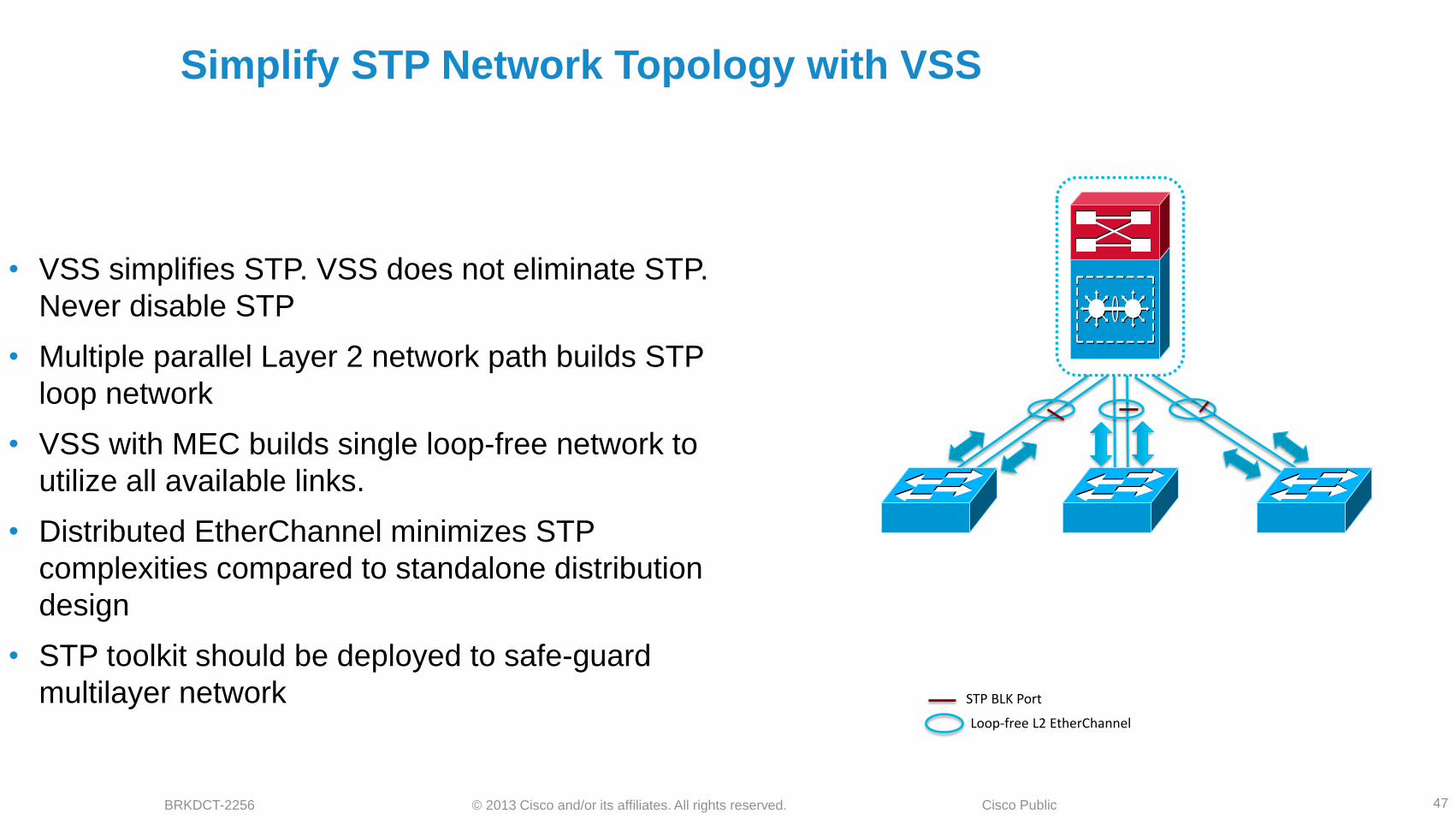
Simplify STP Network Topology with VSS
47
• VSS simplifies STP. VSS does not eliminate STP.
Never disable STP
• Multiple parallel Layer 2 network path builds STP
loop network
• VSS with MEC builds single loop-free network to
utilize all available links.
• Distributed EtherChannel minimizes STP
complexities compared to standalone distribution
design
• STP toolkit should be deployed to safe-guard
multilayer network STP BLK Port
Loop-free L2 EtherChannel

© 2013 Cisco and/or its affiliates. All rights reserved. BRKDCT-2256 Cisco Public
Even with Faster Convergence from RPVST+ We Still Have to
Wait on FHRP Convergence
48
• GLBP offers load balancing within a VLAN
• For Voice, sub-second Hello timer enables < 1 Sec traffic recovery upstream
• Sub-Second protocol timers must be avoided on SSO capable network
FHRP Active FHRP Standby
SiSiSiSi
interface Vlan4
ip address 10.120.4.2 255.255.255.0
standby 1 ip 10.120.4.1
standby 1 timers msec 250 msec 750
standby 1 priority 150
standby 1 preempt
standby 1 preempt delay minimum 180
interface Vlan4
ip address 10.120.4.2 255.255.255.0
glbp 1 ip 10.120.4.1
glbp 1 timers msec 250 msec 750
glbp 1 priority 150
glbp 1 preempt
glbp 1 preempt delay minimum 180
interface Vlan4
ip address 10.120.4.1 255.255.255.0
ip helper-address 10.121.0.5
no ip redirects
vrrp 1 description Master VRRP
vrrp 1 ip 10.120.4.1
vrrp 1 timers advertise msec 250
vrrp 1 preempt delay minimum 180
HSRP Config
GLBP Config
VRRP Config

© 2013 Cisco and/or its affiliates. All rights reserved. BRKDCT-2256 Cisco Public
PIM Needs Timer Tuning Too
49
• Multicast recovery depends on PIM DR failure detection in
Layer 2 network
• PIM routers exchanges PIM expiration time in query
message –
Default Query-Interval – 30 seconds
Expiration – Query Interval x 3
DR Failure Detection – ~90 seconds
• Tune PIM query interval to sub-sec as FHRP for faster
multicast convergence
• Sub-second protocol timer must be avoided on SSO capable
network interface Vlan4
ip pim sparse-mode
ip pim query-interval 250 msec
PIM DR SiSiSiSi

© 2013 Cisco and/or its affiliates. All rights reserved. BRKDCT-2256 Cisco Public
interface Vlan4
ip address 10.120.4.2 255.255.255.0
ip pim sparse-mode
Simplified, Scalable and Reliable L3 Gateway with VSS
50
• Single logical Layer 3 gateway. Eliminates complete need of
implementing FHRP protocols.
• Removes FHRP dependencies and increases Layer 3 network
scalability.
• Hardware based rapid fault-detection and network recovery
with default protocol timers.
• Deterministic network sub-second network convergence in
multiple fault conditions.
Single IP
Gateway
Single PIM
Router
interface Vlan4
ip address 10.120.4.2 255.255.255.0
ip pim sparse-mode
standby 1 ip 10.120.4.1
standby 1 timers msec 250 msec 750
standby 1 priority 150
standby 1 preempt
standby 1 preempt delay minimum 180
ip pim query-interval 250 msec
Standalone
VSS

© 2013 Cisco and/or its affiliates. All rights reserved. BRKDCT-2256 Cisco Public
VLAN 2 VLAN 3 VLAN 2 VLAN 3
SW1
SW1: Single Root Bridge and
Gateway for VLAN 2 and VLAN 3
Single auto synchronized
ARP and CAM Table
HSRP and VRRP Design Consideration
Asymmetric Routing (Unicast Flooding)
51
• Alternating HSRP Active between distribution switches can be used for upstream load balancing, however downstream traffic hits both distribution block switches
• ARP (4 hours) and CAM (5 min) table timer mismatch may build inconsistent tables and cause unicast flooding
• VSS eliminates unicast flooding problem by automatically synchronizing ARP and CAM tables in local and remote switch hardware
VLAN 2
SiSiSiSi
VLAN 3
SW1: Active HSRP and
Root Bridge VLAN 3
VLAN 2 VLAN 3
SW2: Active HSRP and
Root Bridge VLAN 2
CAM Table
Empty for
VLAN 2
CAM Table
Empty for
VLAN 3
B
B B
B
B
SW1 SW2

© 2013 Cisco and/or its affiliates. All rights reserved. BRKDCT-2256 Cisco Public
Multi-Chassis EtherChannel Performs Better In Any Network
Design
52
• Network Recovery mechanic varies in different distribution
design –
Standalone – Protocol and Timer dependent
VSS – Hardware dependent
• VSS logical distribution system –
Single P2P STP Topology
Single Layer 3 gateway
Single PIM DR system
• Distributed and synchronized forwarding table –MAC address,
ARP cache, IGMP
• All links are fully utilized based on Ether-channel load
balancing
0
0.2
0.4
0.6
0.8
1
L2-FHRP L2-MEC
Co
nv
erg
en
ce (
sec)
Upstream Downstream Multicast

© 2013 Cisco and/or its affiliates. All rights reserved. BRKDCT-2256 Cisco Public
timers throttle spf 10 100 5000
timers throttle lsa all 10 100 5000
timers lsa arrival 80
OSPF SPF Tuning
The Best Deployment for Standalone Is Routed Access
53
• Simplified Operation with single control-plane – Routing Protocols
• Improved Network Design – No FHRP, STP, Trunk, VTP etc.
• Optimized Forwarding Topology – Layer 3 ECMP
• Improved convergence with fewer protocols
EIGRP/OSPF
Layer 3
Layer 2
SiSiSiSiHSRP Active
Rootguard
Loopguard or
Bridge Assurance
Bridge Assurance
STP Root
BPDU Guard or
PortFast
Port Security

© 2013 Cisco and/or its affiliates. All rights reserved. BRKDCT-2256 Cisco Public
VSS Simplifies Routed Access
54
• Builds single point-to-point routing peer adjacency with MEC
• EtherChannel delivers deterministic hardware-based network
recovery
• Eliminates adjusting protocol timers and parameters
• Eliminates additional protocols requirements for rapid fault detection
EIGRP / OSPF
Single Adjacency

© 2013 Cisco and/or its affiliates. All rights reserved. BRKDCT-2256 Cisco Public
SiSi
Designated
Router
(High IP Address)
IGMP Querier
(Low IP address)
Designated
Router & IGMP
Querier
Non-DR has to
drop all non-RPF
Traffic
SiSiSiSi SiSi
Routed Access Optimized Multicast Operation
55
• Layer 2 access has two multicast routers on the access subnet, causing one to have to discard frames
• Routed Access has a single multicast router which simplifies management of multicast topology

© 2013 Cisco and/or its affiliates. All rights reserved. BRKDCT-2256 Cisco Public
VSS Optimizes Multicast Performance with Routed Access
56
• Single logical L3 path to RP from access to join
multicast distribution tree
• Single OIL/IIL PIM interface in Multicast Routing
Table
• Increases multicast bandwidth capacity with all
MEC member-links programmed for switching
• Transparent to network faults and provides
deterministic sub-second multicast data
recovery
Single PIM Join Message
Single OIL
OIL = Outgoing Interface List IIL = Incoming Interface List
6500E-VSS#show ip mroute sparse
(*, 239.192.51.8), 3d22h/00:03:20, RP 10.100.100.100, flags: S
Incoming interface: Null, RPF nbr 0.0.0.0
Outgoing interface list:
Port-channel105, Forward/Sparse, 00:16:54/00:02:54
Port-channel101, Forward/Sparse, 00:16:56/00:03:20
(10.125.31.147, 239.192.51.8), 00:16:54/00:02:35, flags: A
Incoming interface: Port-channel105, RPF nbr 10.125.0.21
Outgoing interface list:
Port-channel101, Forward/Sparse, 00:16:54/00:03:20

© 2013 Cisco and/or its affiliates. All rights reserved. BRKDCT-2256 Cisco Public
Routed Access Provides Rapid Convergence with Optimized
Traffic Flow and Ease of Mgmt
57
• CEF and protocol based network recovery in Standalone Routed Access Design EIGRP converges in <200 msec
OSPF with sub-second tuning converges in <200 msec
Multicast with sub-second tuning convergences in ~600 msec
• EtherChannel hash based network recovery in VSS Routed Access Design ‒ Deterministic sub-second unicast & multicast network
convergence
• EtherChannel does not require any further protocol tunings
0
0.1
0.2
0.3
0.4
0.5
0.6
0.7
EIGRP-ECMP EIGRP-MEC OSPF-ECMP OSPF-MEC
Co
nve
rge
nce
(se
c)
Upstream Downstream Multicast

© 2013 Cisco and/or its affiliates. All rights reserved. BRKDCT-2256 Cisco Public
Intra-Chassis Recovery
SiSi SiSi
Inter-Chassis Recovery
Diversify Links For Module Redundancy
58
• Distribute multiple connections to single or logical remote
system between different linecard module when possible.
• Recovery mechanic same as link failure.
• Prevents topology changes or forwarding updates and provides
intra-chassis sub-second recovery.
• Depending network load it minimize the network congestion
SiSi SiSi
VSL
VSL

© 2013 Cisco and/or its affiliates. All rights reserved. BRKDCT-2256 Cisco Public
Best Practice for Module OIR
59
• Module OIR is supported on all modular systems.
• Network recovery have higher impact with Module OIR due to
OIR detection
Hardware Synchronization
Protocol Dependencies
Forwarding Updates
• Minimize network impact with following techniques :
Admin Power Down
Admin Reset
0
0.5
1
1.5
2
2.5
OIR Power Down Soft Reset
Co
nve
rge
nce
(se
c)
Upstream Downstream Multicast
6500E(config)# no power enable module <slot-id>
6500 Standalone
6500-VSS(config)# no power enable switch <1|2> module <slot-id>
6500 VSS
© 2013 Cisco and/or its affiliates. All rights reserved. BRKDCT-2256 Cisco Public
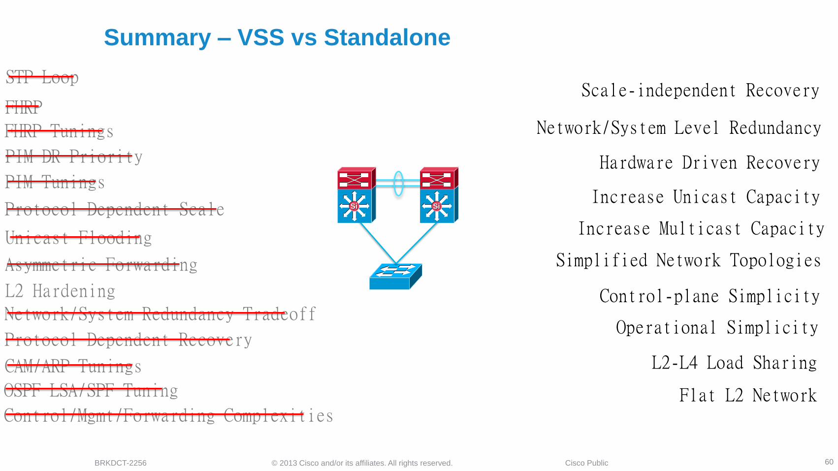
Summary – VSS vs Standalone
60
PIM DR Priority
STP Loop
FHRP
FHRP Tunings
PIM Tunings
Protocol Dependent Scale
Unicast Flooding
Asymmetric Forwarding
L2 Hardening
Protocol Dependent Recovery
Network/System Redundancy Tradeoff
CAM/ARP Tunings
OSPF LSA/SPF Tuning
Control/Mgmt/Forwarding Complexities
Increase Unicast Capacity
Increase Multicast Capacity
Control-plane Simplicity
Operational Simplicity
Flat L2 Network
Hardware Driven Recovery
Network/System Level Redundancy
L2-L4 Load Sharing
Scale-independent Recovery
Simplified Network Topologies
SiSi SiSi

© 2013 Cisco and/or its affiliates. All rights reserved. BRKDCT-2256 Cisco Public
VSS Enabled Campus Core Design
61
Extend VSS architectural benefits to campus core layer
network
VSS enabled core increases capacity, optimizes network
topologies and simplifies system operations
Key VSS enable core best practices :
Protect network availability and capacity with Catalyst 6500E
Sup2T Quad-Sup NSF/SSO
Simplify network topology and routing database with single MEC
Leverage self-engineer VSS and MEC capabilities for deterministic
network fault detection and recovery
Data Center WAN Internet Data Center WAN Internet
SiSi SiSi SiSi SiSi
SiSiSiSi
SiSi SiSiSiSiSiSi
SiSi SiSi

© 2013 Cisco and/or its affiliates. All rights reserved. BRKDCT-2256 Cisco Public
VSS Core Network Design Alternatives
62
VSL
SiSi SiSi
VSL
SiSi SiSi
Single Link Network Design
Physical Design
ECMP MEC
Full-Mesh Network Design
VSL
SiSi SiSi
VSL
SiSi SiSi
Routing Design
SW1
SW1
SW2
SW2
SW1
SW1
SW2
SW2
ECMP Dual MEC Single MEC
Recommended Design : Full-Mesh Physical Network with Single MEC

© 2013 Cisco and/or its affiliates. All rights reserved. BRKDCT-2256 Cisco Public
VSS Core Network Design Analysis
63
Single Link – ECMP Single Link – MEC Full-Mesh – ECMP Full-Mesh – Dual-MEC Full-Mesh – Single MEC
Total physical links 2 2 4 4 4
Total logical links 0 1 0 2 1
Total layer 3 links 2 1 4 2 1
ECMP routing path 2 0 4 2 0
Per switch local forwarding path 1 1 2 2 2
Routing Peers Double Single Quadrupled Double Single
Single link failure recovery mechanic ECMP via VSL ECMP MEC MEC
NSF/SSO benefits No Yes Yes Yes Yes
MEC Load-sharing benefits No No No Yes Yes
Dual-Active Trust Support No Yes No Yes Yes
Fast-Link Notification capability No Yes No Yes Yes
Single Link Failure – Upstream Network Convergence (ave)
Variable ~600 msec ~200-msec <=100 msec <=100 msec
Single Link Failure – Downstream Network Convergence (ave)
Variable ~600 msec ~200-msec <=100 msec <=100 msec
Recommended Best Practice Core routing Design No No No No Yes
© 2013 Cisco and/or its affiliates. All rights reserved. BRKDCT-2256 Cisco Public
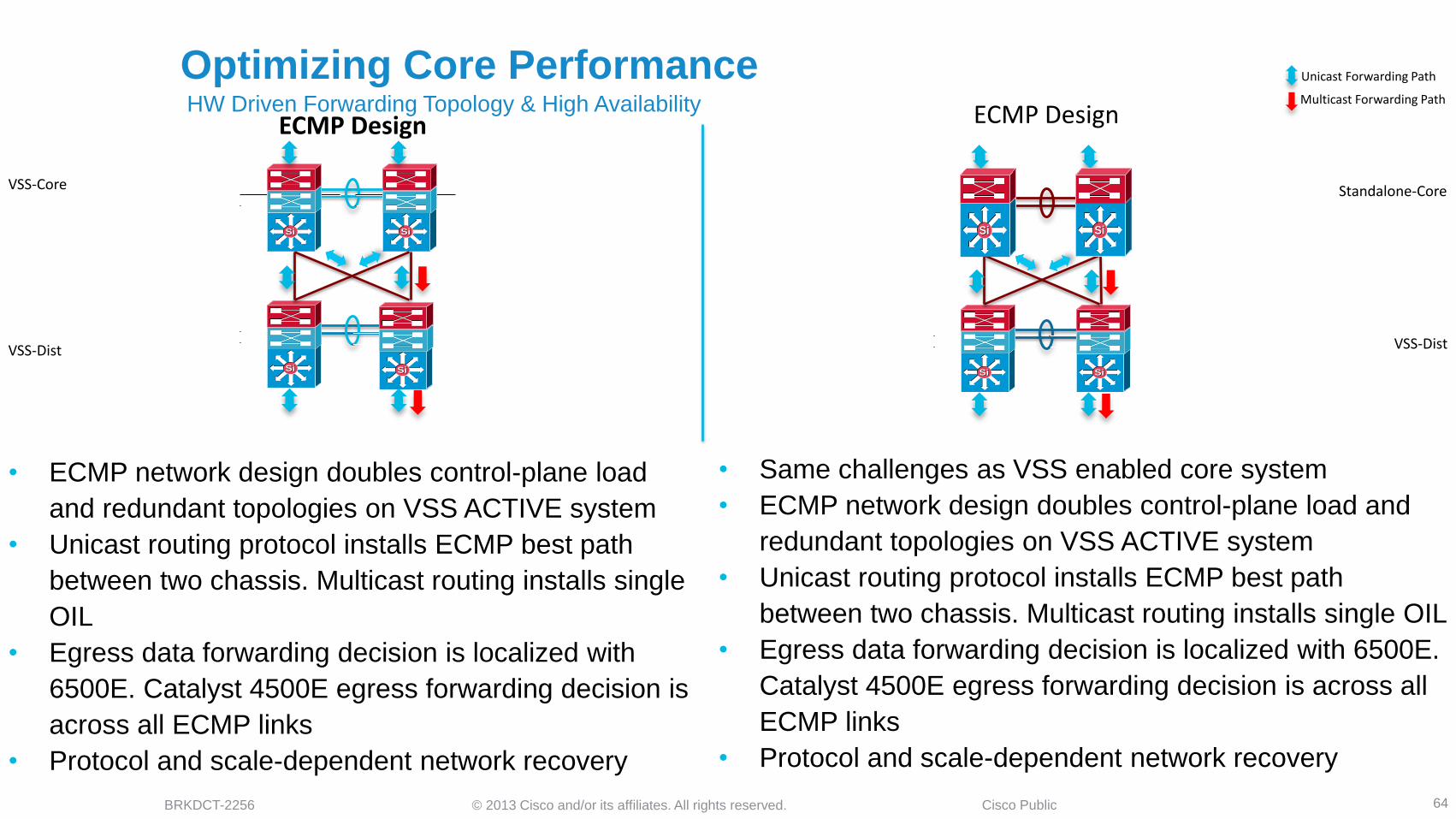
Optimizing Core Performance
64
MEC Design ECMP Design
Unicast Forwarding Path
Multicast Forwarding Path
SiSi SiSi
SiSi SiSi
EC Design ECMP Design HW Driven Forwarding Topology & High Availability
SiSi SiSi
SiSi SiSi
SiSi SiSi
• Single MEC between network layer reduces 50%
control-plane load on VSS ACTIVE system
• Single L3 unicast/multicast neighbor and best path in
table
• Consistent unicast forwarding design. Increase in
multicast switching capacity in core
• Increased unicast and multicast load sharing input
variables
• Protocol and scale-independent network recovery
• ECMP network design doubles control-plane load
and redundant topologies on VSS ACTIVE system
• Unicast routing protocol installs ECMP best path
between two chassis. Multicast routing installs single
OIL
• Egress data forwarding decision is localized with
6500E. Catalyst 4500E egress forwarding decision is
across all ECMP links
• Protocol and scale-dependent network recovery
VSS-Core Standalone-Core
VSS-Dist VSS-Dist
• Dual MEC between network layer maintains original
control-plane load on VSS ACTIVE system
• Dual MEC L3 unicast/multicast neighbor and ECMP
best path in table
• Consistent unicast forwarding design. Increase in
multicast switching capacity in core
• Increased unicast and multicast load sharing input
variables
• Protocol and scale-independent network recovery
• Same challenges as VSS enabled core system
• ECMP network design doubles control-plane load and
redundant topologies on VSS ACTIVE system
• Unicast routing protocol installs ECMP best path
between two chassis. Multicast routing installs single OIL
• Egress data forwarding decision is localized with 6500E.
Catalyst 4500E egress forwarding decision is across all
ECMP links
• Protocol and scale-dependent network recovery

© 2013 Cisco and/or its affiliates. All rights reserved. BRKDCT-2256 Cisco Public
Simple Core Network Design Delivers Deterministic Network
Recovery
65
• Routing Protocol Independent network convergence in large scale campus core
• ECMP Prefix-Independent Convergence (PIC) for with 6500 (VSS/Standalone) from 12.2(33)SXI2
• Cisco Express Forwarding (CEF) optimization in IOS software. No additional configuration or tunings required
• Hardware-based fault detection and recovery in MEC/EC designs
Number or Unicast Routes Core/Distribution – Sup720-10GE
Time for ECMP/MEC Unicast Recovery
0
0.5
1
1.5
2
2.5
3
3.5
500 1000 5000 10000 15000 20000 25000
Co
nve
rgen
ce
(s
ec
)
ECMP (W/o PIC) ECMP (With PIC) MEC
© 2013 Cisco and/or its affiliates. All rights reserved. BRKDCT-2256 Cisco Public
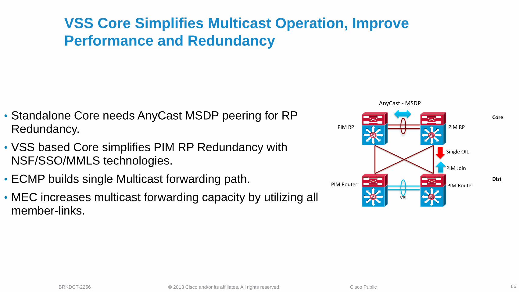
VSS Core Simplifies Multicast Operation, Improve
Performance and Redundancy
66
• Standalone Core needs AnyCast MSDP peering for RP Redundancy.
• VSS based Core simplifies PIM RP Redundancy with NSF/SSO/MMLS technologies.
• ECMP builds single Multicast forwarding path.
• MEC increases multicast forwarding capacity by utilizing all member-links.
Single Logical PIM RP
Single Logical PIM Interface
Dist Single Logical PIM Router
PIM Join
Single Logical OIL
Multiple Multicast Forwarding Paths
Core
SiSi SiSi
PIM RP
Core
PIM RP
SiSi SiSi
PIM Router Dist
PIM Router
AnyCast - MSDP
PIM Join
Single OIL
VSL

© 2013 Cisco and/or its affiliates. All rights reserved. BRKDCT-2256 Cisco Public
Simplified Multicast Network Design Delivers Deterministic
Network Recovery
67
• ECMP multicast recovery is mroute scale dependent could range
in seconds.
• MEC/EC multicast recovery is hardware-based and recovery is
scale-independent in sub-seconds
0
1
2
3
4
5
6
100 500 1000 5000
Co
nve
rge
nc
e (
se
c)
ECMP
MEC/EC
Number or Multicast Routes Core/Distribution – Sup720-10GE
Time for ECMP/MEC Multicast Recovery

© 2013 Cisco and/or its affiliates. All rights reserved. BRKDCT-2256 Cisco Public
End-to-End VSS Design
68
• Single Unified Core System
• Single Point-to-Point routing peers between
network tiers. Reduced control-plane load
and redundant topology database
• Increased Multicast Switching Capacity and
Simplified PIM RP Design
• Protocol and scale-independent sub-second
deterministic network recovery
• Catalyst 6500E VSS Quad-Sup NSF/SSO
protects core network availability and
capacity
Dist
Core
Single System and Network Path Per Campus Layer

© 2013 Cisco and/or its affiliates. All rights reserved. BRKDCT-2256 Cisco Public
• Non Stop Forwarding (NSF) functions with Stateful Switch Over (SSO) to protect data connectivity
• Recovering supervisor and linecard modules uses last-known forwarding information while gracefully rebuilding L3 protocol state-machines
• NSF support variation :
NSF Capable – An redundant system with dual supervisor or route-processor that offers 1+1 redundancy during primary failure, i.e. Catalyst 4500E, 6500E etc.
NSF Helper – The peer system of NSF-capable system that understands and assist in L3 protocols graceful restart process. NSF-Helper system itself can be redundant or non-redundant, i.e. Catalyst 3560X
Neighbor Loss,
Graceful Restart
SiSiSiSi
NSF Restart
RP Restart
OSPF First Hello
NSF Capable
NSF-Aware
Hello
Understanding Non Stop Forwarding Design
69

© 2013 Cisco and/or its affiliates. All rights reserved. BRKDCT-2256 Cisco Public
Implementing NSF
70
4500E(config)#router eigrp <AS#>
4500E(config-router)#nsf
!
4500E#show ip protocols | inc Routing|EIGRP NSF
*** IP Routing is NSF aware ***
Routing Protocol is "eigrp 100"
EIGRP NSF enabled
<snip>
6500E(config)#router ospf <PID#>
6500E(config-router)#nsf (cisco | ietf)
!
6500E#show ip ospf | inc Routing|Non-Stop|NSF
Routing Process "ospf 100" with ID 10.125.100.1
Non-Stop Forwarding enabled
IETF NSF helper support enabled
Cisco NSF helper support enabled
• VSS software design is built on NSF/SSO architecture.
• Catalyst 4500E, 4500X and 6500E deployed in VSS mode must enabled NSF. No configuration required on NSF Helper system
• NSF capability must be manually enabled for all Layer 3 routing protocols :
EIGRP, OSPF, ISIS, BGP, MPLS etc.
• In VRF environment the NSF must be manually enabled on per-VRF IGP instance
• Multicast NSF capability is default ON
EIGRP NSF Configuration
OSPF NSF Configuration
4500E#show ip multicast redundancy state
Multicast IPv4 Redundancy Mode: SSO
<snip>
Multicast Redundancy Configuration
0
2
4
6
8
10
12
14
16
Without NSF With NSF
Co
nve
rge
nc
e (
se
c)
Inter-Chassis NSF/SSO Recovery Analysis
© 2013 Cisco and/or its affiliates. All rights reserved. BRKDCT-2256 Cisco Public
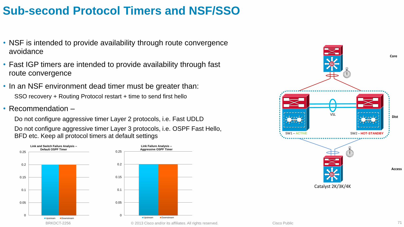
Sub-second Protocol Timers and NSF/SSO
• NSF is intended to provide availability through route convergence avoidance
• Fast IGP timers are intended to provide availability through fast route convergence
• In an NSF environment dead timer must be greater than:
SSO recovery + Routing Protocol restart + time to send first hello
• Recommendation –
Do not configure aggressive timer Layer 2 protocols, i.e. Fast UDLD
Do not configure aggressive timer Layer 3 protocols, i.e. OSPF Fast Hello, BFD etc. Keep all protocol timers at default settings
71
Catalyst 2K/3K/4K
SW1 – ACTIVE
SiSi
SiSi
Access
Dist
Core
VSL
0
0.05
0.1
0.15
0.2
0.25
Link and Switch Failure Analysis – Default OSPF Timer
Upstream Downstream
0
0.05
0.1
0.15
0.2
0.25
Link Failure Analysis – Aggressive OSPF Timer
Upstream Downstream
interface Port-Channel 10 ip ospf dead-interval minimal multiplier 4
SW2 – ACTIVE SW2 – HOT-STANDBY
OSPF dead
timer expired
UDLD dead
timer expired

© 2013 Cisco and/or its affiliates. All rights reserved. BRKDCT-2256 Cisco Public
Advance Virtual Switching System Design Agenda
72
Cisco VSS Architecture
VSS Architecture Overview
Unified System Architecture
Designing VSS System Redundancy
VSS Dual and Quad-Sup Redundancy Design
Virtual Switch Link Design and Best Practices
Designing VSS Network Redundancy
Multi-Chassis EtherChannel and ECMP Design
Load Sharing and Resiliency
Designing VSS Enabled Campus Network
Access Layer
Distribution and Core Layer – Design, Best Practices and Failure Analysis
VSS Dual Active Detection
Understanding Dual Active and Recovery Mechanics
Dual Active Best Practices and Failure Analysis
Summary

© 2013 Cisco and/or its affiliates. All rights reserved. BRKDCT-2256 Cisco Public
SW2 – ACTIVE
Understanding VSS Dual Active Condition
73
• VSL links between VSS switches carries in-band control
plane to maintain various types of virtual-chassis state-
machines
• Failure of all VSL link breaks system virtualization and
leads HOT-STANDBY switch to transition in ACTIVE role
while original ACTIVE switch is still operational. This
system state is known as – Dual-Active
• Dual-Active condition confuses neighbor devices and de-
stabilizes L2 and L3 network with duplicate system
information
• Unstable L2 and L3 network topologies directly impacts
forwarding-plane causing network outage
Control Link Control Link
SW1 – ACTIVE SW2 – HOT-STANDBY
SiSi
SiSiAccess
Dist
Core Duplicate Interface IP
Duplicate IGP/BGP RID
Duplicate Control-Plane (ARP, ICMP…)
Duplicate PAGP/LACP System ID
STP BPDU
Duplicate L2 Control-Plane (CDP, UDLD…)
VSL

© 2013 Cisco and/or its affiliates. All rights reserved. BRKDCT-2256 Cisco Public
VSS Dual-Active Detection Redundancy
74
• Two Detection and Recovery Mechanic :
In-Direct Detection = Enhanced PAgP (ePAgP)
Direct Detection = Dual-Active Fast Hello
• Recommended to use ePAgP and Fast-Hello mechanic for
redundancy on Catalyst 6500E VSS
• Recommended to use multiple trusted ePAgP MECs for
redundancy on Catalyst 4500E / 4500X VSS
• 6500E VSS BFD detection mechanic is deprecated starting
15.0(SY1)
Dual-Sup or Quad-Sup VSL Redundancy
Catalyst 2K/3K/4K
SW1 – ACTIVE
SiSi
SiSi
Access
Dist
Core
SW2 – HOT-STANDBY
VSL
Fast Hello 2
ePAgP Trusted L2 Port-Channel
ePAgP Trusted L3 Port-Channel
1
1
* Dual Active Fast-Hello is in Catalyst 4500E/4500X roadmap
Platform Enhanced PAgP Dual Active Fast Hello BFD
Catalyst 6500E
(Deprecated)
Catalyst 4500E *
Catalyst 4500X *
© 2013 Cisco and/or its affiliates. All rights reserved. BRKDCT-2256 Cisco Public
SW1 – RECOVERY SW1 – ACTIVE
SiSi
SiSi
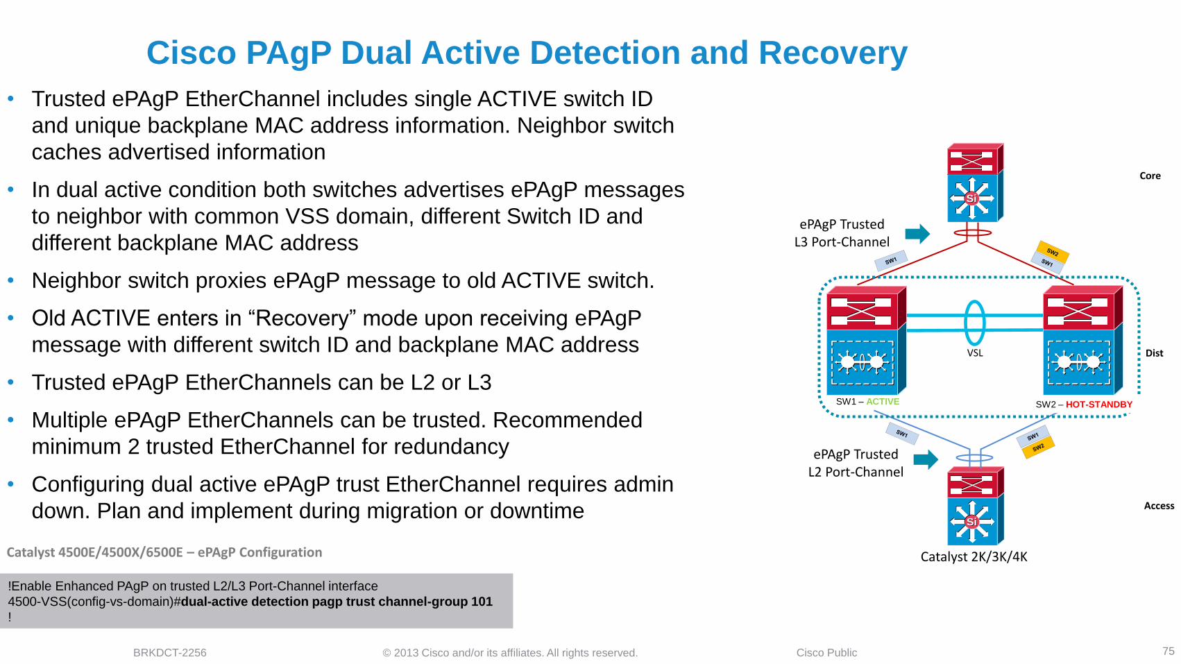
Cisco PAgP Dual Active Detection and Recovery
75
• Trusted ePAgP EtherChannel includes single ACTIVE switch ID
and unique backplane MAC address information. Neighbor switch
caches advertised information
• In dual active condition both switches advertises ePAgP messages
to neighbor with common VSS domain, different Switch ID and
different backplane MAC address
• Neighbor switch proxies ePAgP message to old ACTIVE switch.
• Old ACTIVE enters in “Recovery” mode upon receiving ePAgP
message with different switch ID and backplane MAC address
• Trusted ePAgP EtherChannels can be L2 or L3
• Multiple ePAgP EtherChannels can be trusted. Recommended
minimum 2 trusted EtherChannel for redundancy
• Configuring dual active ePAgP trust EtherChannel requires admin
down. Plan and implement during migration or downtime
ePAgP Trusted L2 Port-Channel
Catalyst 2K/3K/4K
ePAgP Trusted L3 Port-Channel
SW2 – ACTIVE
Access
Dist
Core
SW2 – HOT-STANDBY
VSL
!Enable Enhanced PAgP on trusted L2/L3 Port-Channel interface
4500-VSS(config-vs-domain)#dual-active detection pagp trust channel-group 101
!
Catalyst 4500E/4500X/6500E – ePAgP Configuration
SW1 : ACTIVE SW1 : MAC=A.B.C
SW1 : ACTIVE SW1 : MAC=A.B.C
SW2 : ACTIVE SW2 : MAC=X.Y.Z
SW2 : ACTIVE SW2 : MAC=X.Y.Z

© 2013 Cisco and/or its affiliates. All rights reserved. BRKDCT-2256 Cisco Public
Implementing and Monitoring Dual Active ePAgP
76
!Enable Enhanced PAgP on trusted L2/L3 Port-Channel interface
6500E-VSS(config-vs-domain)#dual-active detection pagp trust channel-group 101
6500E-VSS(config-vs-domain)#dual-active detection pagp trust channel-group 102
!
Catalyst 4500E/4500X/6500E VSS – ePAgP Configuration
Catalyst 2K/3K/4K
SW1 – ACTIVE
SiSi
SiSi
SW2 – HOT-STANDBY
VSL
ePAgP Trusted L2 Port-Channel
ePAgP Trusted L3 Port-Channel
Po101
Po102
ePAgP Client Catalyst Systems Catalyst 2960 * Catalyst 3560X Catalyst 3750X * Catalyst 3850 ** Catalyst 4500E Catalyst 4500X Catalyst 6500E
* Cisco Catalyst 2960 FlexStack and 3750X StackWise-Plus cross-stack do not support ePAgP
** Cisco Catalyst 3850 StackWise-480 cross-stack supports ePAgP
4500E-Access#show pagp dual-active
PAgP dual-active detection enabled: Yes
PAgP dual-active version: 1.1
Channel group 4
Dual-Active Partner Partner Partner
Port Detect Capable Name Port Version
Te1/1 Yes cr2-6500-VSS Te2/2/6 1.1
Te2/1 Yes cr2-6500-VSS Te1/2/6 1.1
ePAgP Client Verification

© 2013 Cisco and/or its affiliates. All rights reserved. BRKDCT-2256 Cisco Public
SW1 – RECOVERY SW2 – ACTIVE
Dual Active Fast Hello Detection and Recovery
77
• Direct dual active detection technique over dedicated fiber/copper
10/100/1000 connection
• In single active state fast hello messages are bi-directionally processed at
every 2 second interval. Accelerates at 200 msec rate upon loosing all VSL
interface
• Dual active is detected if all VSL connections are lost and fast hello message
from peer switch is detected. Old ACTIVE switch enters in recovery mode
• Fast Hello interfaces operates on restricted configuration mode and remains
transparent network topologies
• Up to four Fast Hello interfaces can be configured. Cannot be in EtherChannel
mode
• Supported on Catalyst 6500E*
6500-VSS(config#interface range Gi1/5/1 , Gi2/5/1
6500-VSS(config-if)#dual-active fast-hello
Catalyst 6500E – Dual Active Fast Hello Configuration
* Dual Active Fast-Hello is in Catalyst 4500E/4500X roadmap
Catalyst 2K/3K/4K
SW1 – ACTIVE
SiSi
SiSi
Access
Dist
Core
SW2 – HOT-STANDBY
VSL
Fast Hello
SW1
6500-vss#show switch virtual dual-active fast-hello Fast-hello dual-active detection enabled: Yes Fast-hello dual-active interfaces: Port Local State Peer Port Remote State --------------------------------------------------- Gi1/5/1 Link up Gi2/5/1 Link up 6500-vss#remote command standby-rp show switch virtual dual-active fast-hello Fast-hello dual-active detection enabled: Yes Fast-hello dual-active interfaces: Port Local State Peer Port Remote State --------------------------------------------------- Gi2/5/1 Link up Gi1/5/1 Link up
SW2

© 2013 Cisco and/or its affiliates. All rights reserved. BRKDCT-2256 Cisco Public
6500E Dual-Active Recovery Analysis
78
• Dual-Active Network Recovery depends on –
Uplink Network Design – ECMP vs MEC
Routing Protocols – EIGRP vs OSPF
Detection Mechanic – Fast-Hello vs ePAgP
• OSPF ECMP faster in failure detection then ePAgP. Slow network
convergence
• Starting 12.2(33)SXI3 Dual-Active Fast-Hello performs rapid failure
detection and delivers deterministic recovery independent of network
design and protocol
0
0.1
0.2
0.3
0.4
0.5
EIGRP - ECMP EIGRP - MEC OSPF - ECMP OSPF - MEC
Co
nv
erg
en
ce (
sec)
6500E VSS – Dual-Active Recovery Analysis – Fast-Hello
Upstream Downstream
Dual-Sup or Quad-Sup VSL Redundancy
0
5
10
15
20
25
30
35
EIGRP - ECMP EIGRP - MEC OSPF - ECMP OSPF - MEC
Co
nv
erg
en
ce
(sec)
6500E VSS – Dual-Active Recovery Analysis – ePAgP
Upstream Downstream

© 2013 Cisco and/or its affiliates. All rights reserved. BRKDCT-2256 Cisco Public
“Dirty” Configuration during dual ACTIVE
79
During the dual ACTIVE restoration if configuration on old ACTIVE chassis is unchanged, old ACTIVE will reboot itself after at least one VSL member link is restored
When VSL recovers, a switch in recovery mode will reload and come up as HOT_STANDBY. However, if the configuration is changed (marked dirty by RF config_sync process), the switch will not reload automatically.
Manual reload must be issues on old ACTIVE after configuration has been corrected and saved. Even just entering in configuration mode and exiting will mark the configuration dirty and will force manual intervention
*Apr 6 17:36:33.809: %VSLP-SW1_SP-5-VSL_UP: Ready for Role Resolution with Switch=2, MAC=001a.30e1.6800 over Te1/5/5
*Apr 6 17:36:36.109: %dual ACTIVE-1-VSL_RECOVERED: VSL has recovered during dual ACTIVE situation: Reloading switch 1
… snip …
*Apr 6 17:36:36.145: %VSLP-SW1_SP-5-RRP_MSG: Role change from ACTIVE to HOT_STANDBY and hence need to reload
*Apr 6 17:36:36.145: %VSLP-SW1_SP-5-RRP_MSG: Reloading the system...
*Apr 6 17:36:37.981: %SYS-SW1_SP-5-RELOAD: Reload requested Reload Reason: VSLP HA role change from ACTIVE to HOT_STANDBY.
*Aug 13 04:24:34.716: %dual ACTIVE-1-VSL_RECOVERED: VSL has recovered during dual ACTIVE situation: Reloading switch 2
*Aug 13 04:24:34.716: %VS_GENERIC-5-VS_CONFIG_DIRTY: Configuration has changed. Ignored reload request until configuration is saved
The configuration change on VSL link will parsed during the initialization . The configuration check helps ensure that the VSL-related configurations on the two switches are compatible. If it fails, then the standby chassis comes up in route-processor redundancy (RPR), mode where all modules are powered down.
VSL related configuration changes can be viewed via “show switch virtual redundancy config-mismatch”
The best practice recommendation is to NOT to enter into configuration mode while in dual active however one can not avoid the accidental shut down of VSL link and thus required configuration changes to have proper VSL restoration

© 2013 Cisco and/or its affiliates. All rights reserved. BRKDCT-2256 Cisco Public
VSS Best Practices Summary
• Design each VSS domain with unique ID
• Configure “mac-address use-virtual” under virtual switch configuration mode
• Select appropriate VSS capable system that fits in network and solution
requirements
• Deploy 6500E Quad-sup NSF/SSO for mission-critical networks to protect network
availability and capacity
• Do not compromise network foundation baselines. Deploy full-mesh physical
connections for redundancy and load sharing across the network
• MEC enables network benefits with VSS. Bundle all physical connections into single
logical connection for simplified and resilient network topologies
• Always use link bundling protocols – Cisco PAgP or IETF LACP
• Plan and design VSL with appropriate capacity, diversification and redundancy
80
© 2013 Cisco and/or its affiliates. All rights reserved. BRKDCT-2256 Cisco Public
VSS Best Practices Summary
• Configure “nsf” under L3 routing protocols
• Keep Layer 2 and Layer 3 protocol timers at factory default. Do not enable
protocols with aggressive timers
• Configure redundant dual active trusted ePAgP neighbors (L2/L3)
• Configure redundant dual active mechanics ePAgP and Fast Hello
• Exclude dual active management interface for connectivity and
troubleshooting
81

© 2013 Cisco and/or its affiliates. All rights reserved. BRKDCT-2256 Cisco Public
Summary
• Simplify and Optimize your campus network design with system and
network consolidation to maintain application performance even during
common network faults
• Leverage hardware-based fault detection for scale-independent and
deterministic network recovery
• Build non-stop communication network with system-level redundancy in
all campus layer – Access / Distribution / Core
• Design mission-critical campus backbone that offers scale flexibility, key
foundational services and uncompromised high-availability.
• Reduce maintenance window and upgrade system while maintaining
network availability
82

© 2013 Cisco and/or its affiliates. All rights reserved. BRKDCT-2256 Cisco Public
Recommended Reading
• Continue your Cisco Live learning experience with
further reading from Cisco Press
• Check the Recommended Reading flyer for suggested
books
End-to-End QoS Network Design: Quality of Service in LANs, WANs
and VPNs
ISBN: 1-58705-176-1
Building Resilient IP Networks
ISBN: 1-58705-215-6
Top-Down Network Design, Second Ed.
ISBN: 1-58705-152-4
83
Available Onsite at the Cisco Company Store

© 2013 Cisco and/or its affiliates. All rights reserved. BRKDCT-2256 Cisco Public
Call to Action
• Visit the Cisco Campus at the World of Solutions to experience Cisco innovations in action
• Get hands-on experience attending one of the Walk-in Labs
• Schedule face to face meeting with one of Cisco’s engineers
at the Meet the Engineer center
• Discuss your project’s challenges at the Technical Solutions Clinics
84

© 2013 Cisco and/or its affiliates. All rights reserved. BRKDCT-2256 Cisco Public 85