Embed Size (px)
Citation preview
Advanced Heat Transfer Solutions
1
Advanced Heat Transfer Solutions
2
Advanced Heat Transfer Solutions
3
INDEX
PAGE
Introduction ………………………………………………………………………. 4
Use / warranty…………………...…………………..………..…………………. 4
Name plate ………………...……………………………..…..…………………. 7
Safety instructions ……………………………………… ………………………. 7
Handling ……………...………….……………………………………………….. 8
Storage………………...………………………………………………….. ……… 9
Installation………………………………………...……………………….……… 9
Start-up…………………..……………………………………………………….... 10
Operation…………...…………………………………………………………….. 13
Interruption in operation for short periods ………………………………….. 15
Maintenance..……………………..………….…..……………………............... 15
Replacement of plates and gaskets.………......…...……………………….. 19
Re-assembling of the PHE ………..…………………………….………………. 19
Cleaning of the frame……………………..…….…...……………………........ 21
Problem solving…………………...……………….……………………………… 21
Advanced Heat Transfer Solutions
4
Operation and Maintenance Manual
Plate and Frame heat exchanger, G Series
1. Introduction
First of all it is recommended to keep the present Manual always near the Plate heat
exchanger.
It is moreover of the highest importance that the plate heat exchanger will be used
exactly according to the thermal program calculated at the time of the purchase of
the PHE. It is therefore important and recommended to keep a copy of the technical
specification as well as the Declaration of Conformity together with this manual. Using
the PHE at different conditions as those established on the technical specification,
may be the cause of important differences in the performance or not functioning
properly as it should.
The installation of the PHE as well as future maintenance operations should be carried
out by qualified and instructed personnel only.
If the PHE needs special maintenance or structural changes, in that case please
contact the manufacturer.
2. Use / Warranty
The Onda Plate & Frame PHE must be installed and used respecting the technical
specification (thermal calculation), paying special attention to the following points:
Avoid excessive temperatures which may damage the gaskets (install safety
thermostats)
Avoid “water hammers” which may both damage plates and gaskets. It is
recommended to install a security valve.
Do not use different fluids as those indicated in the technical specification, other
fluids than those chosen in the design of the PHE may not be suitable for the chosen
materials, i.e. plates and gaskets.
Do not use the PHE at higher pressures than the maximum allowed pressure (PS) or
the maximum allowed temperature (TS) as indicated in the technical specification
and on the label attached to the PHE.
The PHE must be used in accordance to the European Directive 97/23/CE (P.E.D.)
If changes to the PHE are required, please contact ONDA for the necessary approval.
Advanced Heat Transfer Solutions
5
Important notice:
Onda warrants its equipment for the duration of 18 months as from the invoice date
on the condition that the equipment has been used correctly according to the
thermic program established in the documents part of the order. In case of a claim,
the customer must be able to show temperatures and pressure on both circuits. For
this purpose a thermometer as well as pressure gauge should be installed.
Defects or inferior performances which are due to the non-respect of the above
recommendations will automatically cancel the warranty.
Warranty is not covered in case of normal wear, corrosion, fouling, or the use of
incompatible fluids, responsible for damage to plates and gaskets.
Terms of the Onda Warranty:
A. ONDA S.p.A. warrants that the Products shall be free from defects in material and
workmanship for a period of 18 months from the date of the delivery.
Therefore, should ONDA S.p.A., within the warranty period, acknowledge and recognise in
writing the existence of the defects in the products and said defects be materially grounded,
ONDA S.p.A. shall, at its discretion, repair the defective Products at no costs for the Client or
replace them by delivering the substitutive products Ex works (Incoterms 2000) at ONDA
S.p.A.’s premises.
ONDA’s facilities located at via LORD Baden Powell, 11 – 36045 Lonigo (VI).
B. Subject to loss of the warranty, notice of any defect shall be given by the Client in
writing with return receipt registered letter within, and not later than, 10 (ten) days from the
date of receipt of the products at the Client’s premises or in the different delivery place,
previously indicated by the latter.
Subject to loss of the warranty, notice of any latent defect of the Products by the Client shall
be given in writing, by return receipt registered letter, within and not later than 10 (ten) days
from the date of the relevant discovery. It is hereby understood that the burden of the proof of
the date of the discovery shall be borne by the Client.
C. ONDA S.p.A. also warrants that the Products are manufactured in compliance with
the Italian and European Laws and Regulations in force on the date of the confirmation by
ONDA S.p.A. of the relevant Client’s order. Unless otherwise expressly agreed in writings by the
parties, Client shall bear any other additional expenses related to the operations of repairing or
replacing of the defective products.
D. This warranty shall not apply should the defects of the Products be caused by:
Advanced Heat Transfer Solutions
6
natural wear and tear;
unauthorised repairs or modifications;
unsuited use or application;
thermal overexposure, also when occasional;
electrical or mechanical over-stress;
failure of respecting the functional and environmental parameters suggested
by ONDA S.p.A. for the correct use and exploitation of the products;
installation of the products not in compliance with the technical specifications
provided by ONDA S.p.A.;
any other cause due to the Client’s negligence or to occasional faults of the
products as consequence of mass-production procedures.
E. This warranty shall also not apply in case of:
non-compliance of the Products with Laws and/or Regulations in force in the place where the
Products are installed and/or assembled by the Client and/or in the place of their final use,
should the Client not expressly require the conformity of the Products to said Laws and
Regulations and not duly inform ONDA S.p.A. of their content before the date of transmission
of the latter's order confirmation.
This limitation of the warranty is also applicable with reference to peculiar Laws and
Regulations valid and binding in States of the European Union independently of the European
Laws and Regulations.
F. In the case of non-compliance of the Products with Italian and/or foreign Laws and/or
Regulations entered in force after the date of transmission of the order confirmation by ONDA
S.p.A., the replacement or any possible adjustment under warranty conditions will not be
applied.
ONDA S.p.A. is, at any rate, not responsible for the use of the Products not conform to Italian
and foreign Laws and/or Regulations entered in force after the date of transmission of their
order confirmation by ONDA S.p.A.
G. The Client shall not sell or market Products not in compliance with the Laws and
Regulations mentioned under letter E-F above. In the negative, the Client shall keep ONDA
S.p.A. harmless of any damage or loss suffered by the latter, due to any third party's and/or
authority's claim raised as a consequence of the manufacture by ONDA S.p.A. of Products not
in compliance with the above mentioned Laws and Regulations.
H. Without prejudice to the application of DPR 224/1988 on product liability and liability
for gross negligence or wilful misconduct, ONDA S.p.A. shall never be liable for direct, indirect
or occasional damages which in any manner derived from defective products.
Advanced Heat Transfer Solutions
7
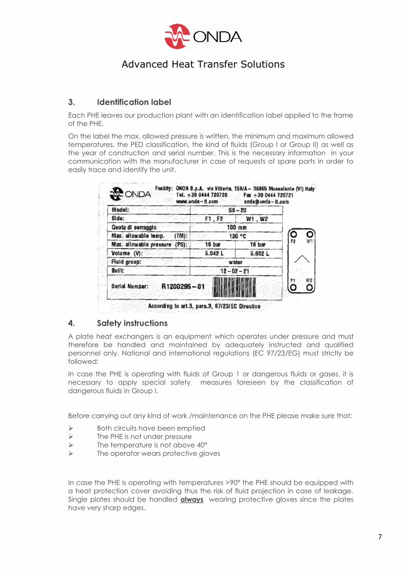
3. Identification label
Each PHE leaves our production plant with an identification label applied to the frame
of the PHE.
On the label the max. allowed pressure is written, the minimum and maximum allowed
temperatures, the PED classification, the kind of fluids (Group I or Group II) as well as
the year of construction and serial number. This is the necessary information in your
communication with the manufacturer in case of requests of spare parts in order to
easily trace and identify the unit.
4. Safety instructions
A plate heat exchangers is an equipment which operates under pressure and must
therefore be handled and maintained by adequately instructed and qualified
personnel only. National and international regulations (EC 97/23/EG) must strictly be
followed:
In case the PHE is operating with fluids of Group 1 or dangerous fluids or gases, it is
necessary to apply special safety measures foreseen by the classification of
dangerous fluids in Group I.
Before carrying out any kind of work /maintenance on the PHE please make sure that:
Both circuits have been emptied
The PHE is not under pressure
The temperature is not above 40°
The operator wears protective gloves
In case the PHE is operating with temperatures >90° the PHE should be equipped with
a heat protection cover avoiding thus the risk of fluid projection in case of leakage.
Single plates should be handled always wearing protective gloves since the plates
have very sharp edges.
Advanced Heat Transfer Solutions
8
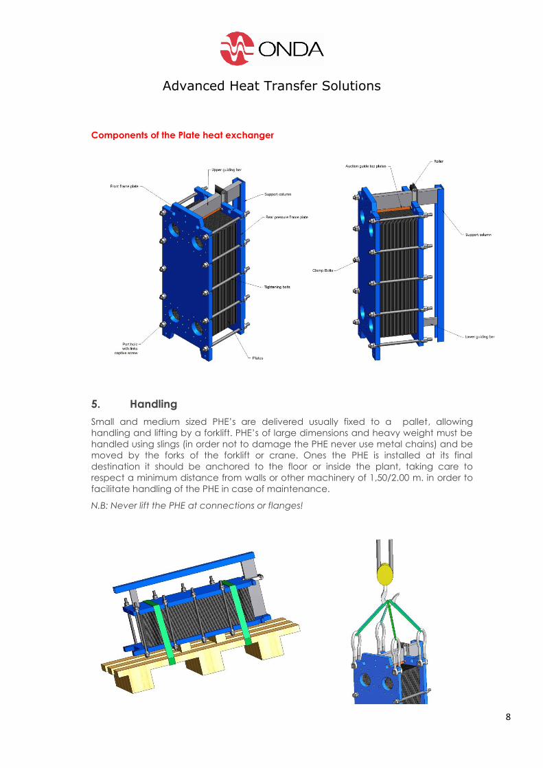
Components of the Plate heat exchanger
5. Handling
Small and medium sized PHE’s are delivered usually fixed to a pallet, allowing
handling and lifting by a forklift. PHE’s of large dimensions and heavy weight must be
handled using slings (in order not to damage the PHE never use metal chains) and be
moved by the forks of the forklift or crane. Ones the PHE is installed at its final
destination it should be anchored to the floor or inside the plant, taking care to
respect a minimum distance from walls or other machinery of 1,50/2.00 m. in order to
facilitate handling of the PHE in case of maintenance.
N.B: Never lift the PHE at connections or flanges!
Advanced Heat Transfer Solutions
9
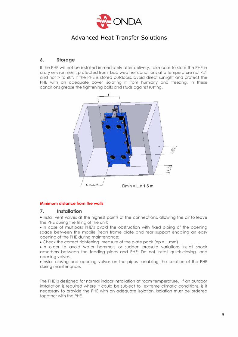
6. Storage
If the PHE will not be installed immediately after delivery, take care to store the PHE in
a dry environment, protected from bad weather conditions at a temperature not <5°
and not > to 60°. If the PHE is stored outdoors, avoid direct sunlight and protect the
PHE with an adequate cover isolating it from humidity and freezing. In these
conditions grease the tightening bolts and studs against rusting.
Minimum distance from the walls
7. Installation
Install vent valves at the highest points of the connections, allowing the air to leave
the PHE during the filling of the unit; In case of multipass PHE’s avoid the obstruction with fixed piping of the opening
space between the mobile (rear) frame plate and rear support enabling an easy
opening of the PHE during maintenance;
Check the correct tightening measure of the plate pack (np x …mm)
In order to avoid water hammers or sudden pressure variations install shock
absorbers between the feeding pipes and PHE; Do not install quick-closing- and
opening valves.
Install closing and opening valves on the pipes enabling the isolation of the PHE
during maintenance.
The PHE is designed for normal indoor installation at room temperature. If an outdoor
installation is required where it could be subject to extreme climatic conditions, is it
necessary to provide the PHE with an adequate isolation. Isolation must be ordered
together with the PHE.
Advanced Heat Transfer Solutions
10
The PHE must be installed on a perfectly flat floor in a vertical position.
8. Start-up of the PHE
Primary circuit:
a. Feed valve between pump and PHE remains closed
b. Open the outlet valve (if installed) on the connection
c. Open the vent
d. Start the pump
e. Make sure the feed valve is opened slowly
f. Make sure the air has completely escaped the PHE and close the vents.
Secondary circuit:
Repeat the same procedure as above.
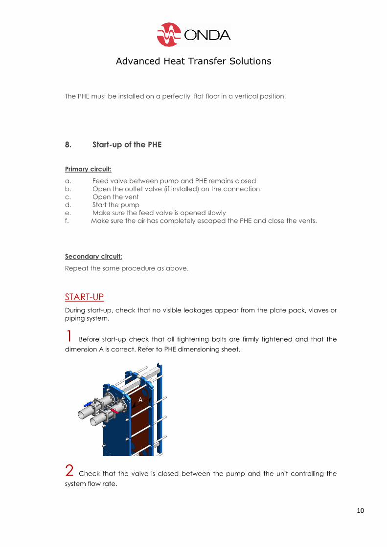
START-UP
During start-up, check that no visible leakages appear from the plate pack, vlaves or
piping system.
1 Before start-up check that all tightening bolts are firmly tightened and that the
dimension A is correct. Refer to PHE dimensioning sheet.
2 Check that the valve is closed between the pump and the unit controlling the
system flow rate.
Advanced Heat Transfer Solutions
11
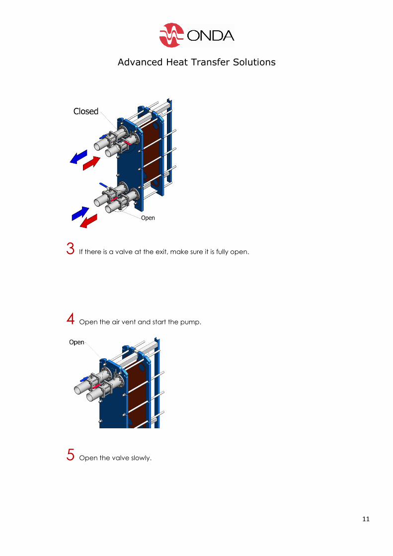
3 If there is a valve at the exit, make sure it is fully open.
4 Open the air vent and start the pump.
5 Open the valve slowly.
Advanced Heat Transfer Solutions
12
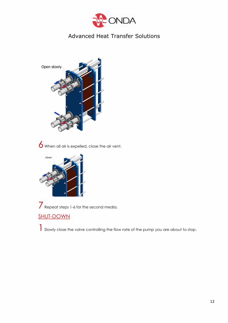
6 When all air is expelled, close the air vent.
7 Repeat steps 1-6 for the second media.
SHUT-DOWN
1 Slowly close the valve controlling the flow rate of the pump you are about to stop.
Advanced Heat Transfer Solutions
13
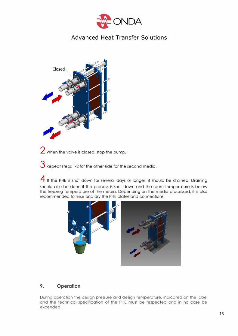
2 When the valve is closed, stop the pump.
3 Repeat steps 1-2 for the other side for the second media.
4 If the PHE is shut down for several days or longer, it should be drained. Draining
should also be done if the process is shut down and the room temperature is below
the freezing temperature of the media. Depending on the media processed, it is also
recommended to rinse and dry the PHE plates and connections.
9. Operation
During operation the design pressure and design temperature, indicated on the label
and the technical specification of the PHE must be respected and in no case be
exceeded.
Advanced Heat Transfer Solutions
14
It is mandatory to avoid sudden temperature exceeding as well as water hammers.
These circumstances may severely damage the PHE’s components and will
automatically cancel the validity of the warranty, releasing the manufacturer from
any liability for damages.
In case a temperature exceeding or water hammer occurs, the PHE must be put out
of operation in order to eliminate the cause of the defect. Under normal operating
circumstances it is recommended to check the perfect functioning of the PHE in the
plant at least ones a year and to check the functional parameters such as pressure,
temperatures and pressure drop on a monthly basis. Changes in these parameters
may be the sign of fouling inside the PHE.
Advanced Heat Transfer Solutions
15
10. Interruption in operation for short periods:
1) Gradually close the feeding valves with priority to the circuit with the highest
pressure;
2) Switch-off the pumps
3) Close the valves on the outlet pipes
For longer interruptions add the following procedure to the points
above:
1. Let the PHE cool-off until room temperature
2. Completely drain both circuits and vent the heat exchanger
3. Rinse the plate package with water and eliminate eventual dirt
4. Unscrew the nuts of the tightening bars in order to loosen the plate package
increasing the tightening dimension by 10% approx.
5. For longer periods tightening bars and nuts should be treated with a rust resisting
grease.
11. Maintenance
Normal maintenance frequency depends on the application and kind of fluids
entering the PHE.
We recommend to do one yearly maintenance during which the PHE should be
completely opened and checked according to pt. 9.
Moreover is it important to check the gaskets which may have lost some of their spring
back: This might require small adjustments in the tightening measure of the plate
pack, which may be tightened until the minimum allowed value. Please check the
label on the PHE where min and max tightening dimensions are mentioned.
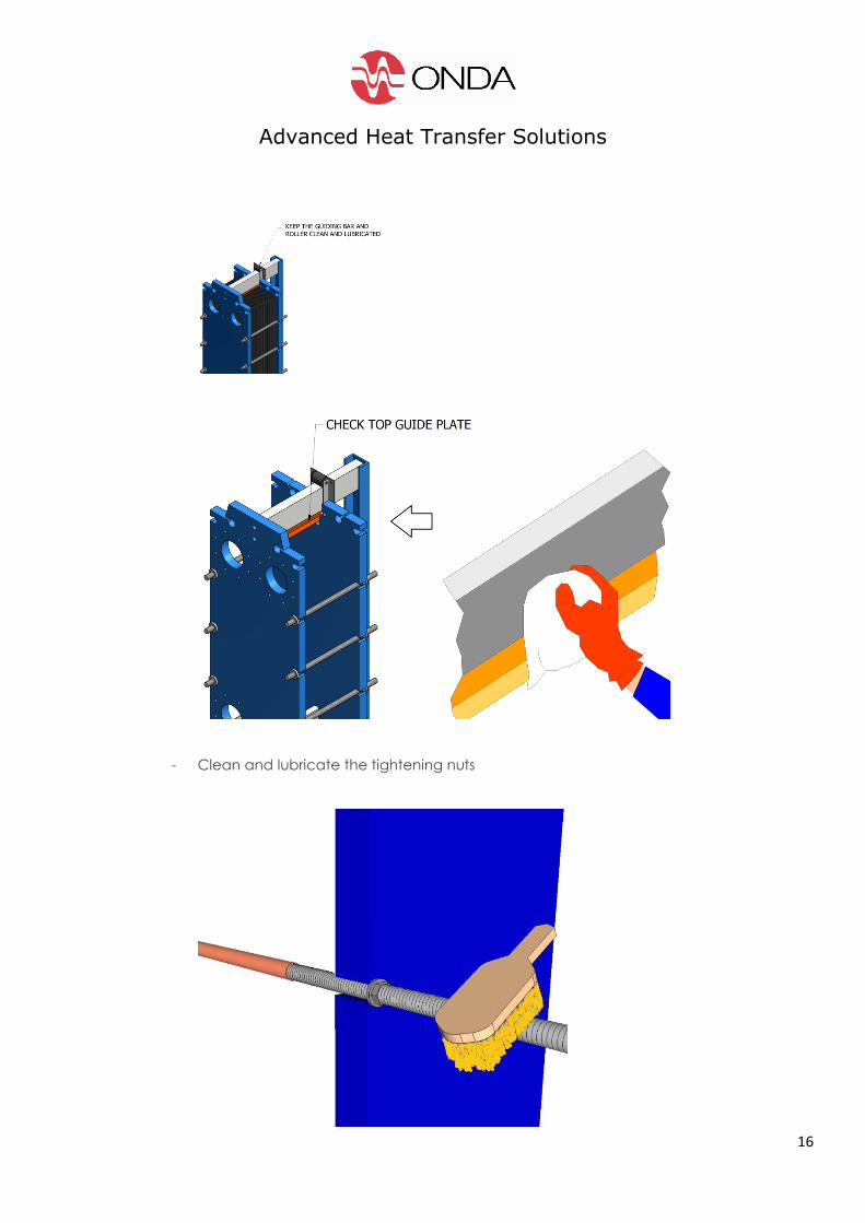
Before opening the PHE the following operations are recommended:
- Clean the plate pack externally, the roller of the guiding bar, upper and under
guiding bar and lubricate the roller;
Advanced Heat Transfer Solutions
16
- Clean and lubricate the tightening nuts
Advanced Heat Transfer Solutions
17
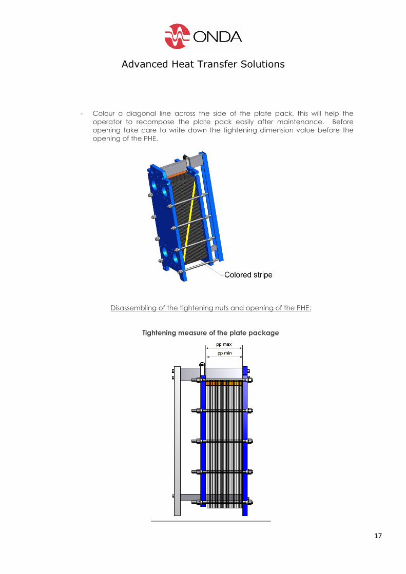
- Colour a diagonal line across the side of the plate pack, this will help the
operator to recompose the plate pack easily after maintenance. Before
opening take care to write down the tightening dimension value before the
opening of the PHE.
Disassembling of the tightening nuts and opening of the PHE:
Tightening measure of the plate package
Advanced Heat Transfer Solutions
18
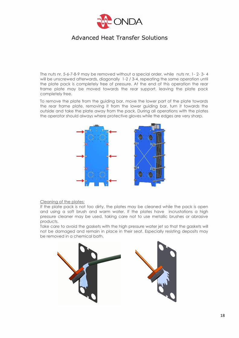
The nuts nr. 5-6-7-8-9 may be removed without a special order, while nuts nr. 1- 2- 3- 4
will be unscrewed afterwards, diagonally 1-2 / 3-4, repeating the same operation until
the plate pack is completely free of pressure. At the end of this operation the rear
frame plate may be moved towards the rear support, leaving the plate pack
completely free.
To remove the plate from the guiding bar, move the lower part of the plate towards
the rear frame plate, removing it from the lower guiding bar, turn it towards the
outside and take the plate away from the pack. During all operations with the plates
the operator should always where protective gloves while the edges are very sharp.
Cleaning of the plates:
If the plate pack is not too dirty, the plates may be cleaned while the pack is open
and using a soft brush and warm water. If the plates have incrustations a high
pressure cleaner may be used, taking care not to use metallic brushes or abrasive
products.
Take care to avoid the gaskets with the high pressure water jet so that the gaskets will
not be damaged and remain in place in their seat. Especially resisting deposits may
be removed in a chemical bath.
Advanced Heat Transfer Solutions
19
Recommended detergents: (check that detergents are suitable for plate and gasket
materials)
Limescale and incrustations: Phosphoric acid at max. 20°, concentration max. 5% for
approx. 1 hour
Oils, greases: Caustic soda solution at 85° , concentration max. 4%
For approx. 24 hrs.
Mud and metal oxides: Nitric acid at 60°, concentration max. 8% or citric acid,
concentration of 4% at max. 60°.
Important:
Do not use hydrochloric acid (HLC) or water with chloride to clean stainless steel
plates;
Do not use phosphoric acid on titanium plates
N.B. Always check and keep strictly to the safety instructions from the detergent
manufacturer.
12. Replacement of plates and gaskets
The gaskets are fixed easily into their seat, without the need of glues inside the groove.
Before fixing the new gasket to the plate, accurately clean the groove.
13. Re-assembling of the PHE
Check that both plate sand gaskets are perfectly clean. The smallest impurity may
be the cause of a leakage.
Lubricate the upper guiding bar.
Re-arrange the plates back into the PHE frame according to the assembly scheme,
in reverse order. Pay attention to the first and final plate which are in direct contact
to the front and rear frame plate. The gasket of the first plate must be placed against
the rear (fixed) frame plate. Check the correct plate pack assembly by observing the
coloured diagonal line applied before the disassembling. Moreover if the plate pack
is correctly assembled the external side of the plate pack form a regular honeycomb
design. Small plate heat exchangers may be re-assembled in a horizontal position
lying on the rear (fixed) plate.
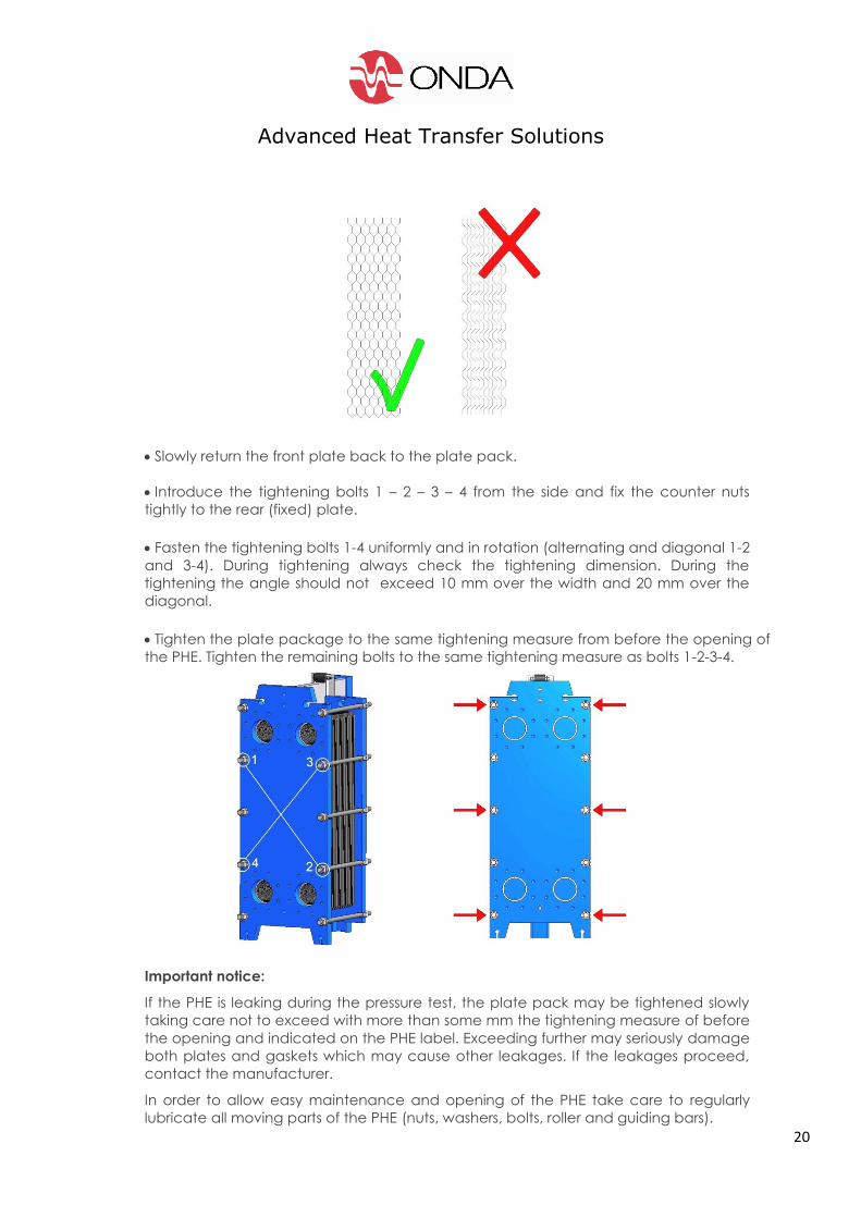
Correct assembling of the plate package
Advanced Heat Transfer Solutions
20
Slowly return the front plate back to the plate pack.
Introduce the tightening bolts 1 – 2 – 3 – 4 from the side and fix the counter nuts
tightly to the rear (fixed) plate.
Fasten the tightening bolts 1-4 uniformly and in rotation (alternating and diagonal 1-2
and 3-4). During tightening always check the tightening dimension. During the
tightening the angle should not exceed 10 mm over the width and 20 mm over the
diagonal.
Tighten the plate package to the same tightening measure from before the opening of
the PHE. Tighten the remaining bolts to the same tightening measure as bolts 1-2-3-4.
Important notice:
If the PHE is leaking during the pressure test, the plate pack may be tightened slowly
taking care not to exceed with more than some mm the tightening measure of before
the opening and indicated on the PHE label. Exceeding further may seriously damage
both plates and gaskets which may cause other leakages. If the leakages proceed,
contact the manufacturer.
In order to allow easy maintenance and opening of the PHE take care to regularly
lubricate all moving parts of the PHE (nuts, washers, bolts, roller and guiding bars).
Advanced Heat Transfer Solutions
21
14. Cleaning of the frame:
The frame, made of painted carbon steel, may be cleaned with a sponge, cloth or
brush, using a slightly alkaline solution. In case the painting of the frame is damaged it
is recommended to repair the painting as soon as possible.
15. Problem solving
Fluid leakage between connections and fixed plate (leakage from connections at
frame plate):
This could be due to:
- Mechanical stresses on the connections
- Faulty ring gasket, connection or flange
- Material fatigue or wear
Solutions:
- Check correct tightening of the bolts
- Check eventual mechanical stresses from the piping system on the gasket
- Check the correct alignment of the piping and flanges and eventually correct if
necessary
Fluid leakage between plate package and fix/mobile frame plate (leakage from the
bottom)
This could be due to:
- Faulty gasket between plate and inside area of the frame plate
- Faulty gasket or fault in the groove of the first gasket
- Material fatigue or wear
Solutions:
- Identify and sign the place of leakage with a marker
- Open the PHE following the procedure at pt. 11
- Check whether the first gasket is correctly seated in its groove and touching the
frame plate;
External Leakage from the plate package
This could be due to:
- Exceeding of the allowed temperature/pressure
- The mobile frame plate is not tightened plane-parallel
- Wrong tightening measure
- Faulty or damaged gaskets
- Wear of the gaskets
Advanced Heat Transfer Solutions
22
Solutions:
- Correct pressure and temperature to design values
- If necessary, tighten the frame plate until perfect plane-parallel position. If
necessary correct tightening dimensions (increasing or diminishing) very carefully
taking care not to exceed the tightening dimensions more than some millimetres.
The difference between the tightening measure between single bolts should not
exceed more than 2 mm.
- If after the above solutions no result is obtained, open the PHE and check the
correct positioning of aIl gaskets it the groove, replace eventual damaged
gaskets.
Internal leakage / mixture of the fluids
This could be due to:
- Corrosion of the plate
- Crack in the plate
Solutions:
- Open the PHE
- Empty one of both circuits
- Disconnect the tubes to the emptied circuit
- Give a slight pressure to the second and still connected circuit
- The fluid escapes through the leakage to the open circuit and then leaves the PHE
through the connections.
- Using a strong light enables to locate the faulty plate
- Check the complete plate and its gasket, clean them and if necessary replace
them both.
In case of a very small crack on the plate which is invisible to the eye, each plate and
gasket of the plate pack should be checked, replacing the eventual faulty plate’s if
any, as well as its gasket. In case no fault is found a complete crack test will be
required in order to find the faulty plates. In that case please contact the
manufacturer.
The performance is seriously diminishing
If the pressure drop is increasing, or the performance decreases seriously, first check if
the cause is due to the production plant, externally to the PHE, for example change in
the fluids, the temperatures or the flow rates). If the PHE does not improve its
performance stopping the operation of the PHE, opening and cleaning is necessary.
Max. tightening measure has been reached
Advanced Heat Transfer Solutions
23
If the gaskets, due to fatigue or wear have completely lost their flexibility and have
been compressed at the maximum limit, the gaskets will not be able to guarantee
the perfect leak-tightness. All gaskets must be replaced.