Embed Size (px)
Citation preview
Advanced Hydraulics
Prof. Dr. Suresh. A. Kartha
Department of Civil Engineering
Indian Institute of Technology, Guwahati
Module - 6
Turbines
Lecture - 4
Turbines, Cavitation
Very good afternoon to everyone, so we are going through our lecture series on advanced
hydraulics and we are in the sixth module on turbines. So, this is the fourth lecture of this
particular module and with this lecture, we are intending to wind up the entire syllabus
also. And that way, we would like to conclude this entire lecture series as well.
(Refer Slide Time: 00:50)
If you recall in the last class, we had especially discussed on pumps. So, pumps we
applied the angular momentum equation to the centrifugal pump impeller, we also
obtained the Euler turbine equations. Then we worked on a sample problem using those
same equations and all, we demonstrated that how it can be applied for the actual
conditions with that example. How the effect of blade or the blade angle can cause
change in head? That was briefly suggested; we just briefly covered what is meant by

axial flow pumps, what is meant by mixed flow pumps. Then in the positive
displacement pumps, we suggested reciprocating pumps, where you use pistons, you
have rotary pumps. So today, we will start about discussion about turbines as well as just
briefly we will cover on cavitation.
(Refer Slide Time: 01:59)
Turbines what do you mean by turbines? Turbines it extract energy from the fluid and
they supply it to other sources right that is how we studied the entire turbine, it is having
function opposite to pump. Pump from the external source you take energy, and supply it
to fluid whereas, in turbine you take energy from the fluid and supply it to some other
source, some other objects and all most common form of turbine is means, you where
mostly you might have heard about turbines used in extracting energy from water having
hydraulic head and convert it to electric energy.
Most of the hydropower projects work on this particular principle, that is using the high
hydraulic head of water, they will run the turbines that will subsequently run the
generators from which you can get electrical energy and all. We will be approaching the
turbines with the same concept throughout our course; we have used the Reynolds
transport theorem control volume approach.
Same thing you can utilize here we may not go for extensive demonstration of the
control volume approach in turbines, but still I am suggesting that you can easily derive
the thing already for the motor, we have seen it for a centrifugal pump impeller blade
inlet and outlet. If you consider it the control using the control volume approach, a
similar phenomenon one can use for turbines also.
(Refer Slide Time: 03:53)
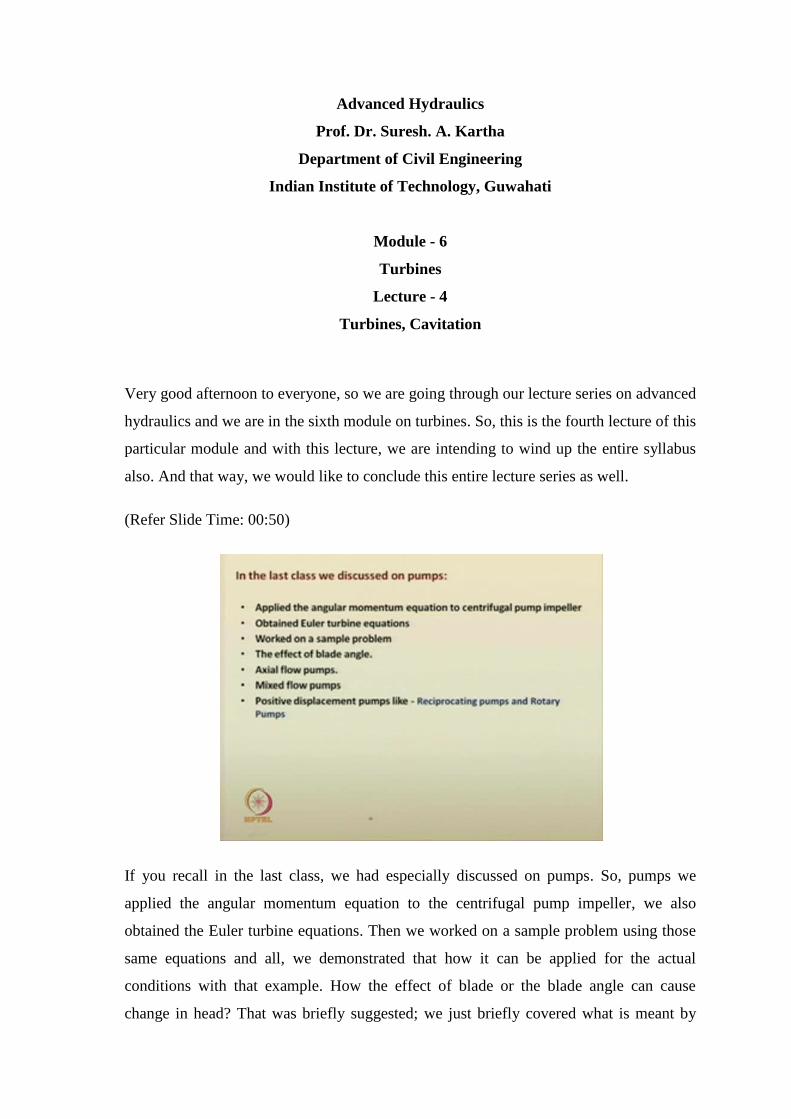
So, turbines just we have given some arbitrary figure and all the turbines consist; there
are mainly two types of turbines - reaction turbines and impulse turbines. What is meant
by reaction turbine? Reaction turbine, the water fills in the blade passages subsequent
which will cause pressure drop or head change within the impeller, that is as the water
fills means water is entirely filled in the blade passages, then it drops it pressure or it
causes change in head in the impeller itself, and it is transmitted.
So, these are reaction turbine we will see a fundamental equation on related to this thing
or fundamental expression, from which we can decide which is, which is reaction
turbine, which is impulse turbine and all. Impulse turbine in the meaning of impulse
turbine is water passes through a nozzle to form high speed jet, which strikes a blade as
they pass through them.
It can have various types of impulse turbines and all, but the meaning is that suppose, if
you have this blades like this high speed jet just hit it. Now, what happens a high speed
jet when it hits, it will rotate, right, this wheel starts rotating. Similarly, it hits like that
continuously and it goes on rotating and if this wheel is mounted on an impeller that
impeller can run further, some machines and all means it is connected. You can generate
some energy or that is it is used for rotating some device right that is the objective here.
So, impulse turbine water passes through a nozzles so, what would be it is high speed jet
is being transmitted here.
(Refer Slide Time: 06:09)
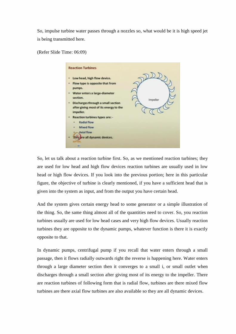
So, let us talk about a reaction turbine first. So, as we mentioned reaction turbines; they
are used for low head and high flow devices reaction turbines are usually used in low
head or high flow devices. If you look into the previous portion; here in this particular
figure, the objective of turbine is clearly mentioned, if you have a sufficient head that is
given into the system as input, and from the output you have certain head.
And the system gives certain energy head to some generator or a simple illustration of
the thing. So, the same thing almost all of the quantities need to cover. So, you reaction
turbines usually are used for low head cases and very high flow devices. Usually reaction
turbines they are opposite to the dynamic pumps, whatever function is there it is exactly
opposite to that.
In dynamic pumps, centrifugal pump if you recall that water enters through a small
passage, then it flows radially outwards right the reverse is happening here. Water enters
through a large diameter section then it converges to a small i, or small outlet when
discharges through a small section after giving most of its energy to the impeller. There
are reaction turbines of following form that is radial flow, turbines are there mixed flow
turbines are there axial flow turbines are also available so they are all dynamic devices.
(Refer Slide Time: 08:14)
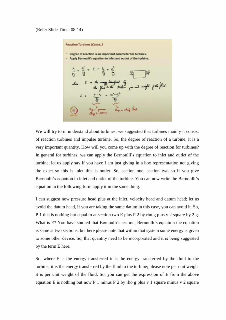
We will try to in understand about turbines, we suggested that turbines mainly it consist
of reaction turbines and impulse turbine. So, the degree of reaction of a turbine, it is a
very important quantity. How will you come up with the degree of reaction for turbines?
In general for turbines, we can apply the Bernoulli’s equation to inlet and outlet of the
turbine, let us apply say if you have I am just giving in a box representation not giving
the exact so this is inlet this is outlet. So, section one, section two so if you give
Bernoulli’s equation to inlet and outlet of the turbine. You can now write the Bernoulli’s
equation in the following form apply it in the same thing.
I can suggest now pressure head plus at the inlet, velocity head and datum head; let us
avoid the datum head, if you are taking the same datum in this case, you can avoid it. So,
P 1 this is nothing but equal to at section two E plus P 2 by rho g plus v 2 square by 2 g.
What is E? You have studied that Bernoulli’s section, Bernoulli’s equation the equation
is same at two sections, but here please note that within that system some energy is given
to some other device. So, that quantity need to be incorporated and it is being suggested
by the term E here.
So, where E is the energy transferred it is the energy transferred by the fluid to the
turbine, it is the energy transferred by the fluid to the turbine; please note per unit weight
it is per unit weight of the fluid. So, you can get the expression of E from the above
equation E is nothing but now P 1 minus P 2 by rho g plus v 1 square minus v 2 square
by 2 g. So, you are getting two terms here, what are they, what is this particular term?
Drop in pressure, right?
So, we can consider means even in open channel hydraulics, and all earlier cases
normally we consider hydrostatic conditions. So, this pressure may also be in a
hydrostatic condition, it is a static pressure at that particular section or it is some static
pressure. Let us consider it as pressure term. So, this is change in pressure or drop in
pressure or change in pressure. So, this is change in pressure quantity and this particular
quantity is drop in velocity head.
So, the energy transferred by the fluid to the turbine it includes change in pressure, as
well as change in velocity head. These two conditions if you can now keep in mind that
based on these two phenomena that is change pressure, and change in velocity. One can
infer whether a turbine is working on the basis of reaction formula, or whether it is
working on the basis of impulsive techniques.
(Refer Slide Time: 13:04)
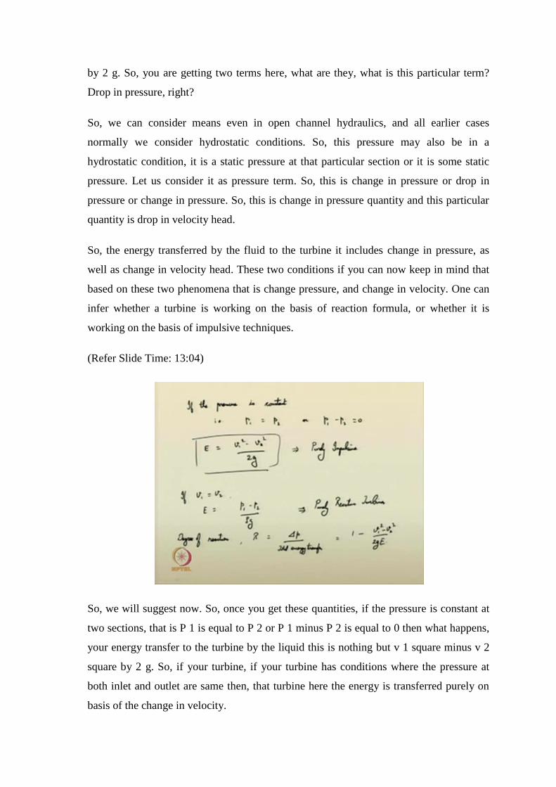
So, we will suggest now. So, once you get these quantities, if the pressure is constant at
two sections, that is P 1 is equal to P 2 or P 1 minus P 2 is equal to 0 then what happens,
your energy transfer to the turbine by the liquid this is nothing but v 1 square minus v 2
square by 2 g. So, if your turbine, if your turbine has conditions where the pressure at
both inlet and outlet are same then, that turbine here the energy is transferred purely on
basis of the change in velocity.
So, such turbines are purely impulsive in nature so, purely impulsive turbines. What way,
what happens in the other way around? If v 1 is equal to v 2 if there is no change in
velocity of liquid that much. So, that in that case your E is nothing but equal to P1 minus
P2 by rho g, such turbines are purely reactive turbines. So, your turbine may not be in the
actual case, your turbine may not be purely impulsive or purely reactive. You can now,
but find some degree of reaction, in turbines based on that suppose if the degree of
reaction is quite high you can suggest that it comes under, the category of reaction
turbines if the degree of reaction, if it is very less it can come under the category of
impulse turbines.
So, mostly most of the turbines in these cases which are in the practical cases, they will
change pressure head and velocity head to a certain extent. So, it is not that the velocity
head will be totally neglected only the change in pressure is being in it, it cannot happen
like that. So, there will be some minor changes one may be more significant the other
may be less significant.
So, based on those phenomenon degree of reaction can also a terminology called degree
of reaction, can also be incorporated. So, I can suggest degree of reaction. So, the degree
of reaction it can be given as R this is nothing but del P by total energy transfer. So, if
you will see that it comes to be about del P is nothing but P 1 minus P 2. So, this comes
to be about roughly around v 1 square minus v 2 square by 2 g like that one can evaluate
the degree of reaction.
(Refer Slide Time: 16:38)
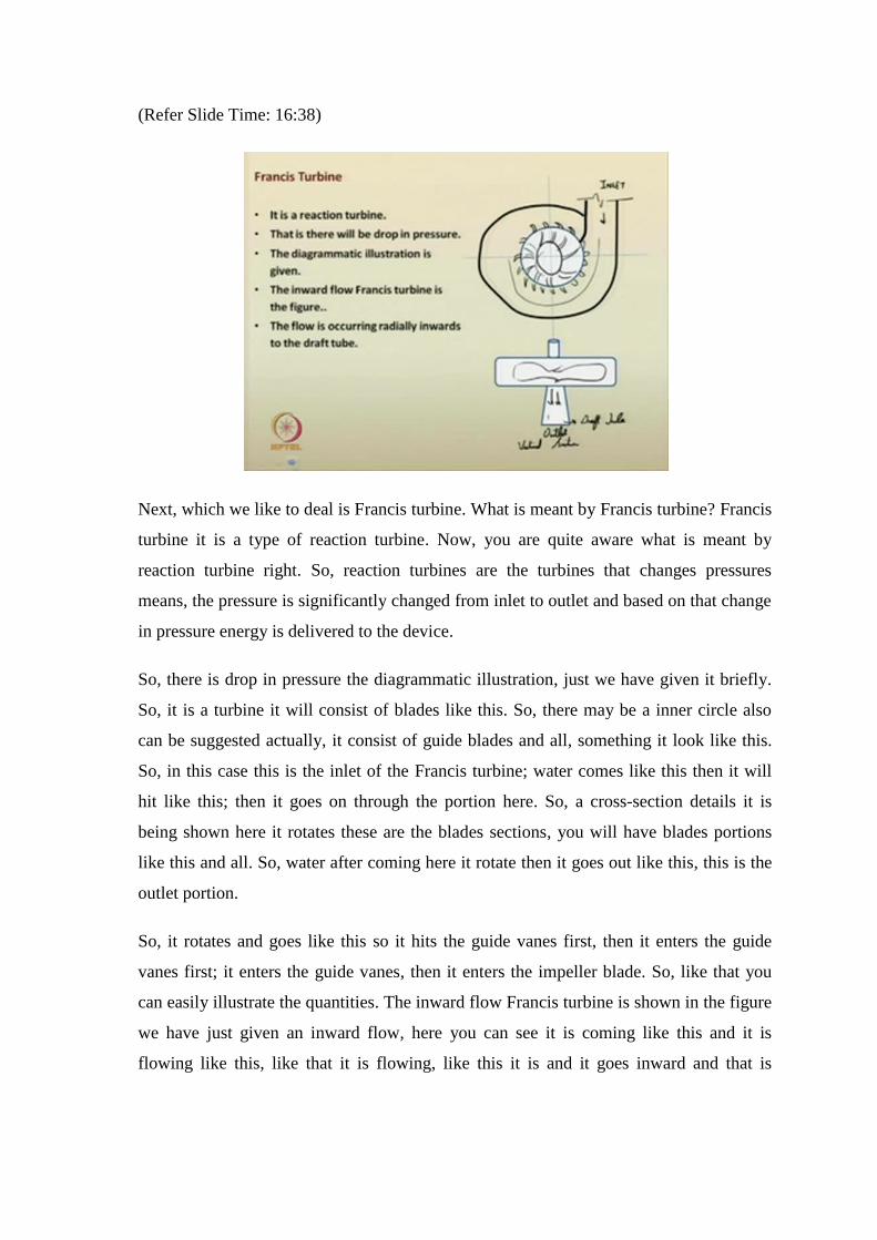
Next, which we like to deal is Francis turbine. What is meant by Francis turbine? Francis
turbine it is a type of reaction turbine. Now, you are quite aware what is meant by
reaction turbine right. So, reaction turbines are the turbines that changes pressures
means, the pressure is significantly changed from inlet to outlet and based on that change
in pressure energy is delivered to the device.
So, there is drop in pressure the diagrammatic illustration, just we have given it briefly.
So, it is a turbine it will consist of blades like this. So, there may be a inner circle also
can be suggested actually, it consist of guide blades and all, something it look like this.
So, in this case this is the inlet of the Francis turbine; water comes like this then it will
hit like this; then it goes on through the portion here. So, a cross-section details it is
being shown here it rotates these are the blades sections, you will have blades portions
like this and all. So, water after coming here it rotate then it goes out like this, this is the
outlet portion.
So, it rotates and goes like this so it hits the guide vanes first, then it enters the guide
vanes first; it enters the guide vanes, then it enters the impeller blade. So, like that you
can easily illustrate the quantities. The inward flow Francis turbine is shown in the figure
we have just given an inward flow, here you can see it is coming like this and it is
flowing like this, like that it is flowing, like this it is and it goes inward and that is
existing. So, this is the vertical section, so, it is the cut section like this if you. The flow
is occurring radially inwards to the draft tube, it is called the draft tube.
(Refer Slide Time: 19:53)
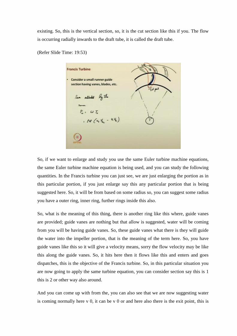
So, if we want to enlarge and study you use the same Euler turbine machine equations,
the same Euler turbine machine equation is being used, and you can study the following
quantities. In the Francis turbine you can just see, we are just enlarging the portion as in
this particular portion, if you just enlarge say this any particular portion that is being
suggested here. So, it will be from based on some radius so, you can suggest some radius
you have a outer ring, inner ring, further rings inside this also.
So, what is the meaning of this thing, there is another ring like this where, guide vanes
are provided; guide vanes are nothing but that allow is suggested, water will be coming
from you will be having guide vanes. So, these guide vanes what there is they will guide
the water into the impeller portion, that is the meaning of the term here. So, you have
guide vanes like this so it will give a velocity means, sorry the flow velocity may be like
this along the guide vanes. So, it hits here then it flows like this and enters and goes
dispatches, this is the objective of the Francis turbine. So, in this particular situation you
are now going to apply the same turbine equation, you can consider section say this is 1
this is 2 or other way also around.
And you can come up with from the, you can also see that we are now suggesting water
is coming normally here v 0, it can be v 0 or and here also there is the exit point, this is
exit point. So, within this portion if you apply the control volume, this is inlet. So, you
have the control volume around this portion, in that marked portion. So, you can just
recall the pump mechanism, same theory we are going to apply. Now, I am repeating it
here so, consider the small runner guide section having vanes blades etc.
So, what we are just trying to do is now, we and we just suggesting power extracted by
the runner, say you have the means here a runner is there right. So, that power extracted
by the runner through the flow of liquid or say this is the runner, this is or you can
suggest this also. So, power extracted by the runner, this is P can be given as omega into
torque rho q, we are using the turbine equation u 2 v T 2, u 1 v T 1 right. In this case u v
T 2 and v T 1 they are not 0, in this particular situation. So, that you need to incorporate
it you can also see that subsequently.
(Refer Slide Time: 24:16)
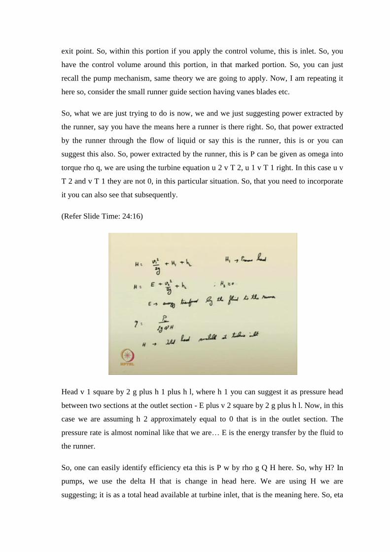
Head v 1 square by 2 g plus h 1 plus h l, where h 1 you can suggest it as pressure head
between two sections at the outlet section - E plus v 2 square by 2 g plus h l. Now, in this
case we are assuming h 2 approximately equal to 0 that is in the outlet section. The
pressure rate is almost nominal like that we are… E is the energy transfer by the fluid to
the runner.
So, one can easily identify efficiency eta this is P w by rho g Q H here. So, why H? In
pumps, we use the delta H that is change in head here. We are using H we are
suggesting; it is as a total head available at turbine inlet, that is the meaning here. So, eta
is equal to P w by rho g Q how based on the total head available at the inlet, how much
quantity you can efficiently use it, that is the meaning here.
(Refer Slide Time: 26:06)
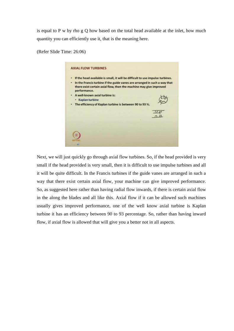
Next, we will just quickly go through axial flow turbines. So, if the head provided is very
small if the head provided is very small, then it is difficult to use impulse turbines and all
it will be quite difficult. In the Francis turbines if the guide vanes are arranged in such a
way that there exist certain axial flow, your machine can give improved performance.
So, as suggested here rather than having radial flow inwards, if there is certain axial flow
in the along the blades and all like this. Axial flow if it can be allowed such machines
usually gives improved performance, one of the well know axial turbine is Kaplan
turbine it has an efficiency between 90 to 93 percentage. So, rather than having inward
flow, if axial flow is allowed that will give you a better not in all aspects.
(Refer Slide Time: 27:36)
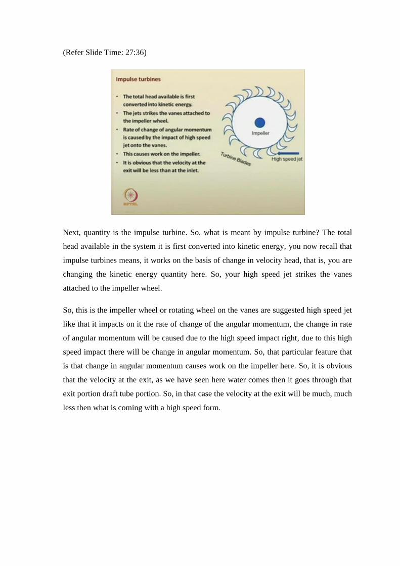
Next, quantity is the impulse turbine. So, what is meant by impulse turbine? The total
head available in the system it is first converted into kinetic energy, you now recall that
impulse turbines means, it works on the basis of change in velocity head, that is, you are
changing the kinetic energy quantity here. So, your high speed jet strikes the vanes
attached to the impeller wheel.
So, this is the impeller wheel or rotating wheel on the vanes are suggested high speed jet
like that it impacts on it the rate of change of the angular momentum, the change in rate
of angular momentum will be caused due to the high speed impact right, due to this high
speed impact there will be change in angular momentum. So, that particular feature that
is that change in angular momentum causes work on the impeller here. So, it is obvious
that the velocity at the exit, as we have seen here water comes then it goes through that
exit portion draft tube portion. So, in that case the velocity at the exit will be much, much
less then what is coming with a high speed form.
(Refer Slide Time: 24:16)
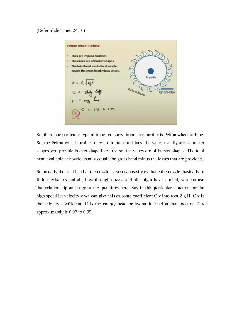
So, there one particular type of impeller, sorry, impulsive turbine is Pelton wheel turbine.
So, the Pelton wheel turbines they are impulse turbines, the vanes usually are of bucket
shapes you provide bucket shape like this; so, the vanes are of bucket shapes. The total
head available at nozzle usually equals the gross head minus the losses that are provided.
So, usually the total head at the nozzle is, you can easily evaluate the nozzle, basically in
fluid mechanics and all, flow through nozzle and all, might have studied, you can use
that relationship and suggest the quantities here. Say in this particular situation for the
high speed jet velocity v we can give this as some coefficient C v into root 2 g H, C v is
the velocity coefficient, H is the energy head or hydraulic head at that location C v
approximately is 0.97 to 0.99.
(Refer Slide Time: 30:51)
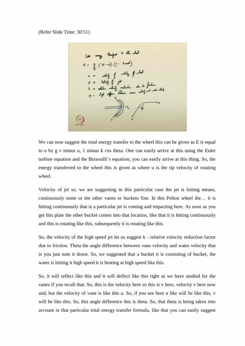
We can now suggest the total energy transfer to the wheel this can be given as E is equal
to u by g v minus u, 1 minus k cos theta. One can easily arrive at this using the Euler
turbine equation and the Bernoulli’s equation; you can easily arrive at this thing. So, the
energy transferred to the wheel this is given as where u is the tip velocity of rotating
wheel.
Velocity of jet so, we are suggesting in this particular case the jet is hitting means,
continuously some or the other vanes or buckets fine. In this Pelton wheel the… it is
hitting continuously that is a particular jet is coming and impacting here. As soon as you
get this plate the other bucket comes into that location, like that it is hitting continuously
and this is rotating like this, subsequently it is rotating like this.
So, the velocity of the high speed jet let us suggest k - relative velocity reduction factor
due to friction. Theta the angle difference between vane velocity and water velocity that
is you just note it down. So, we suggested that a bucket it is consisting of bucket, the
water is hitting it high speed it is heating at high speed like this.
So, it will reflect like this and it will deflect like this right as we have studied for the
vanes if you recall that. So, this is the velocity here so this is v here, velocity v here now
and, but the velocity of vane is like this u. So, if you see here u like will be like this, v
will be like this. So, this angle difference this is theta. So, that theta is being taken into
account in that particular total energy transfer formula, like that you can easily suggest
the energy that is being suggested, transfer to the impeller you can all so now suggest
efficiency.
(Refer Slide Time: 34:34)
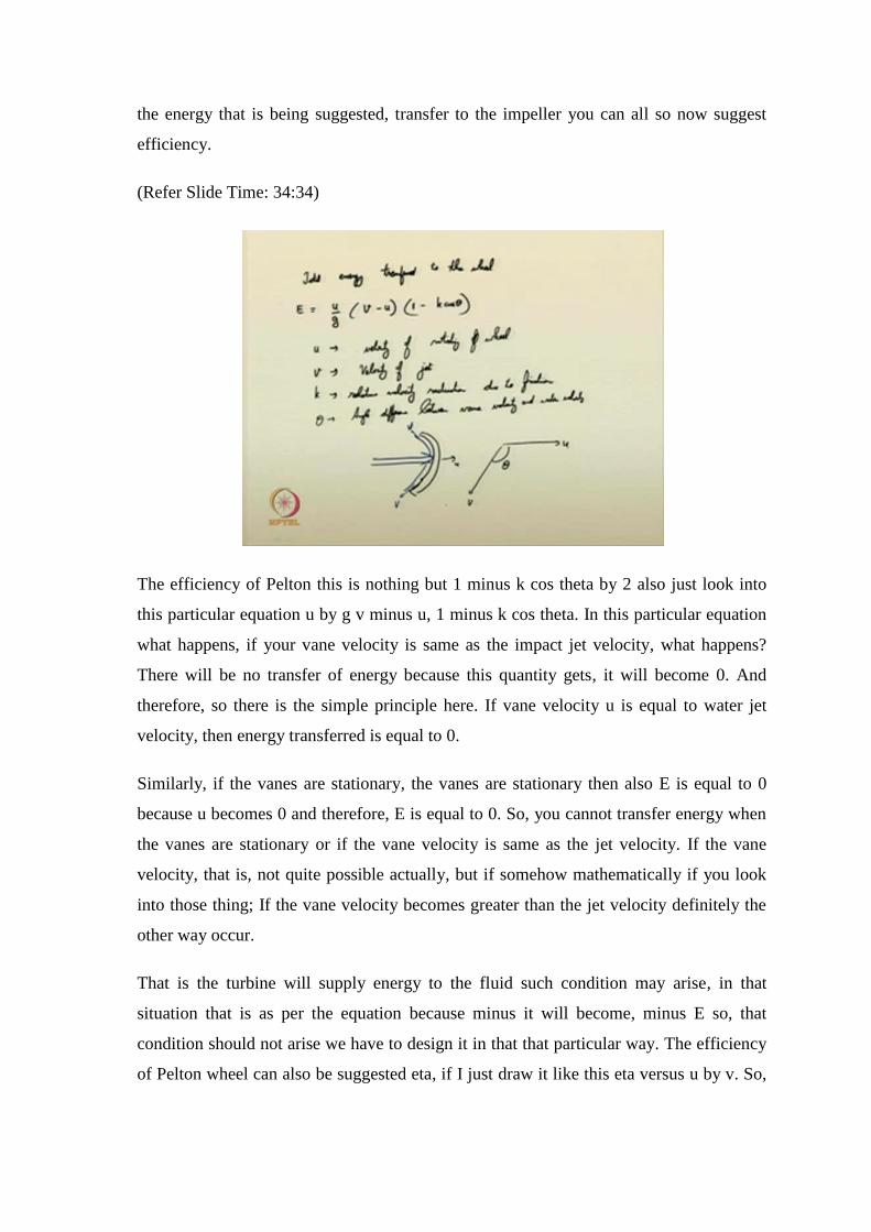
The efficiency of Pelton this is nothing but 1 minus k cos theta by 2 also just look into
this particular equation u by g v minus u, 1 minus k cos theta. In this particular equation
what happens, if your vane velocity is same as the impact jet velocity, what happens?
There will be no transfer of energy because this quantity gets, it will become 0. And
therefore, so there is the simple principle here. If vane velocity u is equal to water jet
velocity, then energy transferred is equal to 0.
Similarly, if the vanes are stationary, the vanes are stationary then also E is equal to 0
because u becomes 0 and therefore, E is equal to 0. So, you cannot transfer energy when
the vanes are stationary or if the vane velocity is same as the jet velocity. If the vane
velocity, that is, not quite possible actually, but if somehow mathematically if you look
into those thing; If the vane velocity becomes greater than the jet velocity definitely the
other way occur.
That is the turbine will supply energy to the fluid such condition may arise, in that
situation that is as per the equation because minus it will become, minus E so, that
condition should not arise we have to design it in that that particular way. The efficiency
of Pelton wheel can also be suggested eta, if I just draw it like this eta versus u by v. So,
it will come something of like this curve and all and this is something around, 0.45
something around like this at 1 u by v is equal to 1, it is 0 definitely it is 0.
(Refer Slide Time: 37:44)
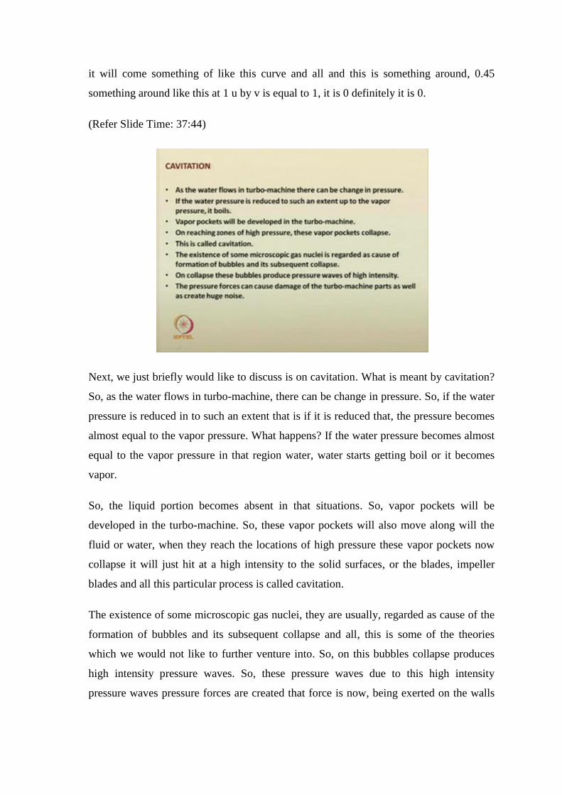
Next, we just briefly would like to discuss is on cavitation. What is meant by cavitation?
So, as the water flows in turbo-machine, there can be change in pressure. So, if the water
pressure is reduced in to such an extent that is if it is reduced that, the pressure becomes
almost equal to the vapor pressure. What happens? If the water pressure becomes almost
equal to the vapor pressure in that region water, water starts getting boil or it becomes
vapor.
So, the liquid portion becomes absent in that situations. So, vapor pockets will be
developed in the turbo-machine. So, these vapor pockets will also move along will the
fluid or water, when they reach the locations of high pressure these vapor pockets now
collapse it will just hit at a high intensity to the solid surfaces, or the blades, impeller
blades and all this particular process is called cavitation.
The existence of some microscopic gas nuclei, they are usually, regarded as cause of the
formation of bubbles and its subsequent collapse and all, this is some of the theories
which we would not like to further venture into. So, on this bubbles collapse produces
high intensity pressure waves. So, these pressure waves due to this high intensity
pressure waves pressure forces are created that force is now, being exerted on the walls
of the turbo-machine equipments. So, it can cause damage to the turbo-machine parts
also, which and also it creates huge noise when it is being rotated so.
(Refer Slide Time: 39:50)
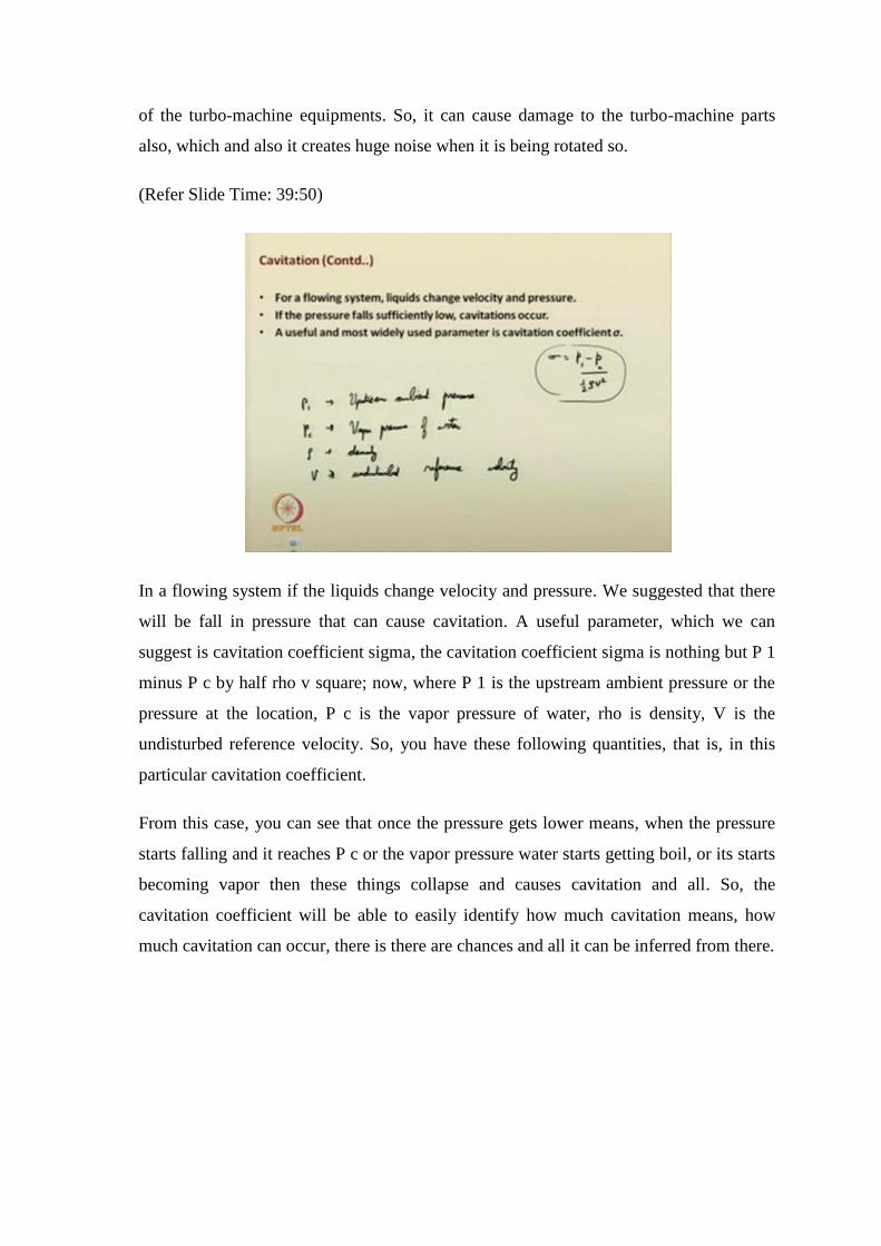
In a flowing system if the liquids change velocity and pressure. We suggested that there
will be fall in pressure that can cause cavitation. A useful parameter, which we can
suggest is cavitation coefficient sigma, the cavitation coefficient sigma is nothing but P 1
minus P c by half rho v square; now, where P 1 is the upstream ambient pressure or the
pressure at the location, P c is the vapor pressure of water, rho is density, V is the
undisturbed reference velocity. So, you have these following quantities, that is, in this
particular cavitation coefficient.
From this case, you can see that once the pressure gets lower means, when the pressure
starts falling and it reaches P c or the vapor pressure water starts getting boil, or its starts
becoming vapor then these things collapse and causes cavitation and all. So, the
cavitation coefficient will be able to easily identify how much cavitation means, how
much cavitation can occur, there is there are chances and all it can be inferred from there.
(Refer Slide Time: 42:19)
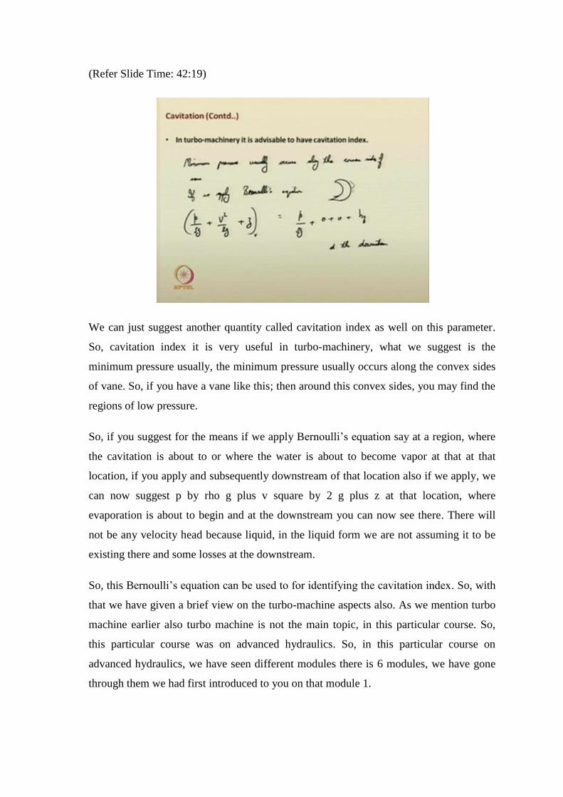
We can just suggest another quantity called cavitation index as well on this parameter.
So, cavitation index it is very useful in turbo-machinery, what we suggest is the
minimum pressure usually, the minimum pressure usually occurs along the convex sides
of vane. So, if you have a vane like this; then around this convex sides, you may find the
regions of low pressure.
So, if you suggest for the means if we apply Bernoulli’s equation say at a region, where
the cavitation is about to or where the water is about to become vapor at that at that
location, if you apply and subsequently downstream of that location also if we apply, we
can now suggest p by rho g plus v square by 2 g plus z at that location, where
evaporation is about to begin and at the downstream you can now see there. There will
not be any velocity head because liquid, in the liquid form we are not assuming it to be
existing there and some losses at the downstream.
So, this Bernoulli’s equation can be used to for identifying the cavitation index. So, with
that we have given a brief view on the turbo-machine aspects also. As we mention turbo
machine earlier also turbo machine is not the main topic, in this particular course. So,
this particular course was on advanced hydraulics. So, in this particular course on
advanced hydraulics, we have seen different modules there is 6 modules, we have gone
through them we had first introduced to you on that module 1.
(Refer Slide Time: 44:58)
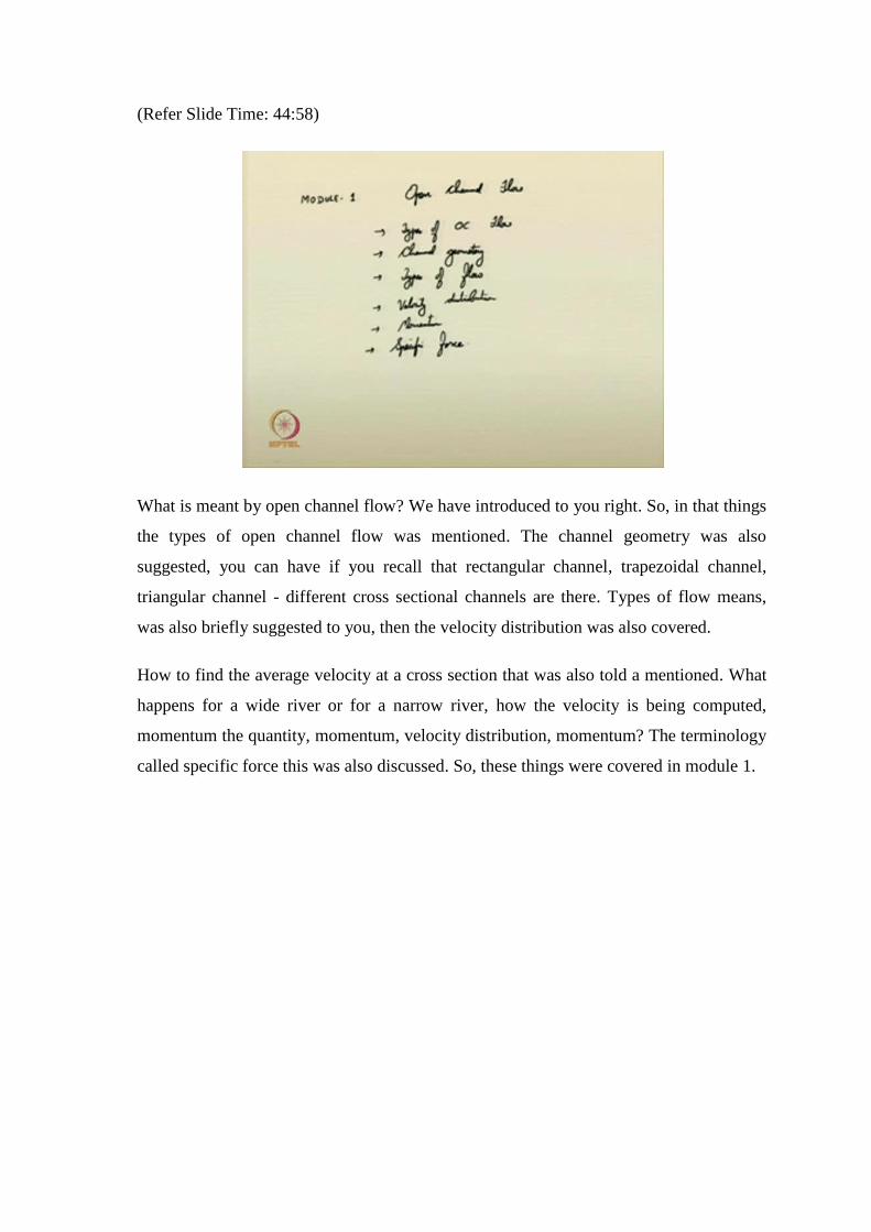
What is meant by open channel flow? We have introduced to you right. So, in that things
the types of open channel flow was mentioned. The channel geometry was also
suggested, you can have if you recall that rectangular channel, trapezoidal channel,
triangular channel - different cross sectional channels are there. Types of flow means,
was also briefly suggested to you, then the velocity distribution was also covered.
How to find the average velocity at a cross section that was also told a mentioned. What
happens for a wide river or for a narrow river, how the velocity is being computed,
momentum the quantity, momentum, velocity distribution, momentum? The terminology
called specific force this was also discussed. So, these things were covered in module 1.
(Refer Slide Time: 46:30)
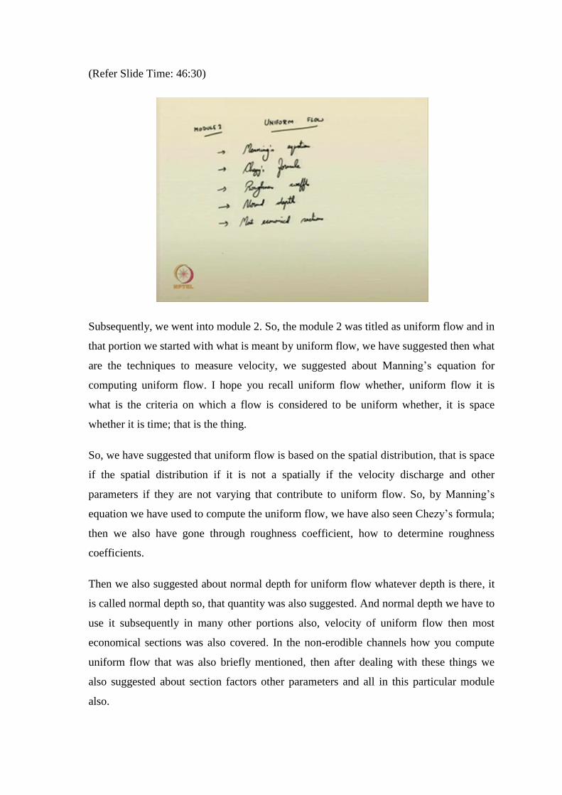
Subsequently, we went into module 2. So, the module 2 was titled as uniform flow and in
that portion we started with what is meant by uniform flow, we have suggested then what
are the techniques to measure velocity, we suggested about Manning’s equation for
computing uniform flow. I hope you recall uniform flow whether, uniform flow it is
what is the criteria on which a flow is considered to be uniform whether, it is space
whether it is time; that is the thing.
So, we have suggested that uniform flow is based on the spatial distribution, that is space
if the spatial distribution if it is not a spatially if the velocity discharge and other
parameters if they are not varying that contribute to uniform flow. So, by Manning’s
equation we have used to compute the uniform flow, we have also seen Chezy’s formula;
then we also have gone through roughness coefficient, how to determine roughness
coefficients.
Then we also suggested about normal depth for uniform flow whatever depth is there, it
is called normal depth so, that quantity was also suggested. And normal depth we have to
use it subsequently in many other portions also, velocity of uniform flow then most
economical sections was also covered. In the non-erodible channels how you compute
uniform flow that was also briefly mentioned, then after dealing with these things we
also suggested about section factors other parameters and all in this particular module
also.
(Refer Slide Time: 48:55)
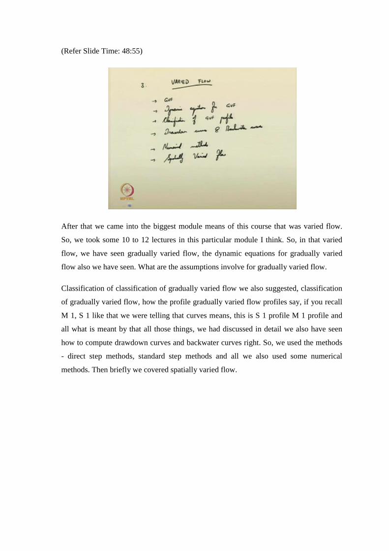
After that we came into the biggest module means of this course that was varied flow.
So, we took some 10 to 12 lectures in this particular module I think. So, in that varied
flow, we have seen gradually varied flow, the dynamic equations for gradually varied
flow also we have seen. What are the assumptions involve for gradually varied flow.
Classification of classification of gradually varied flow we also suggested, classification
of gradually varied flow, how the profile gradually varied flow profiles say, if you recall
M 1, S 1 like that we were telling that curves means, this is S 1 profile M 1 profile and
all what is meant by that all those things, we had discussed in detail we also have seen
how to compute drawdown curves and backwater curves right. So, we used the methods
- direct step methods, standard step methods and all we also used some numerical
methods. Then briefly we covered spatially varied flow.
(Refer Slide Time: 50:48)
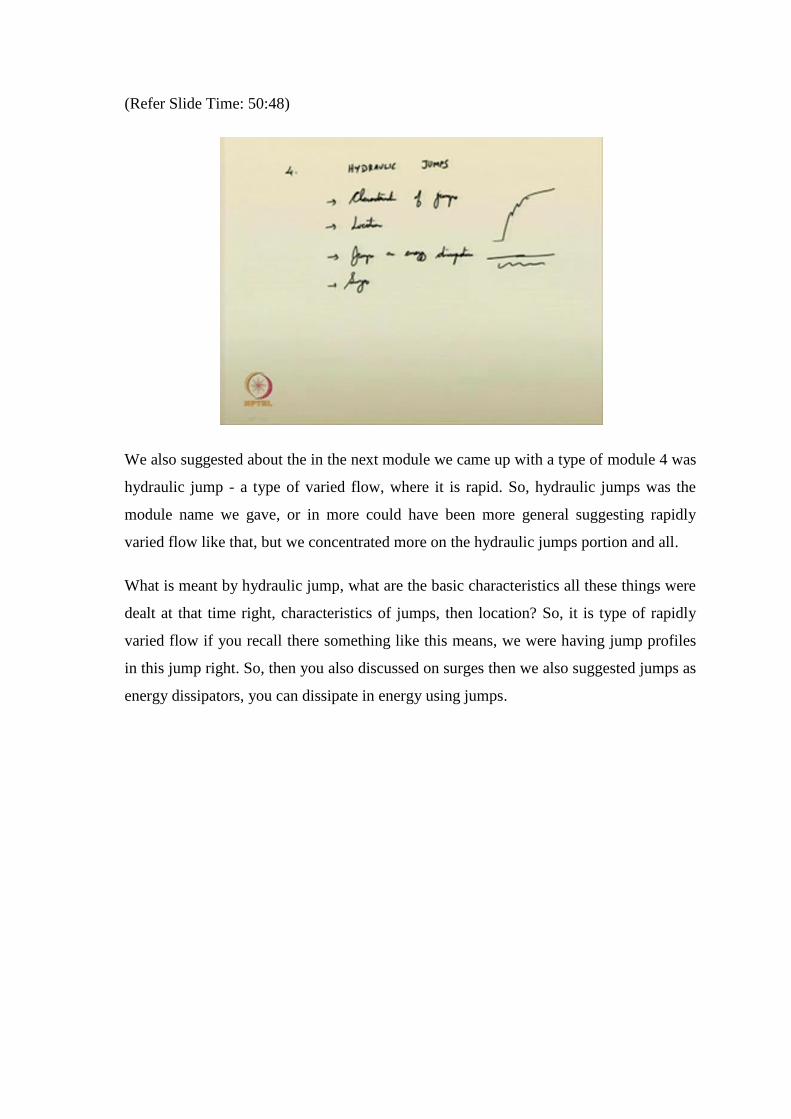
We also suggested about the in the next module we came up with a type of module 4 was
hydraulic jump - a type of varied flow, where it is rapid. So, hydraulic jumps was the
module name we gave, or in more could have been more general suggesting rapidly
varied flow like that, but we concentrated more on the hydraulic jumps portion and all.
What is meant by hydraulic jump, what are the basic characteristics all these things were
dealt at that time right, characteristics of jumps, then location? So, it is type of rapidly
varied flow if you recall there something like this means, we were having jump profiles
in this jump right. So, then you also discussed on surges then we also suggested jumps as
energy dissipators, you can dissipate in energy using jumps.
(Refer Slide Time: 52:11)
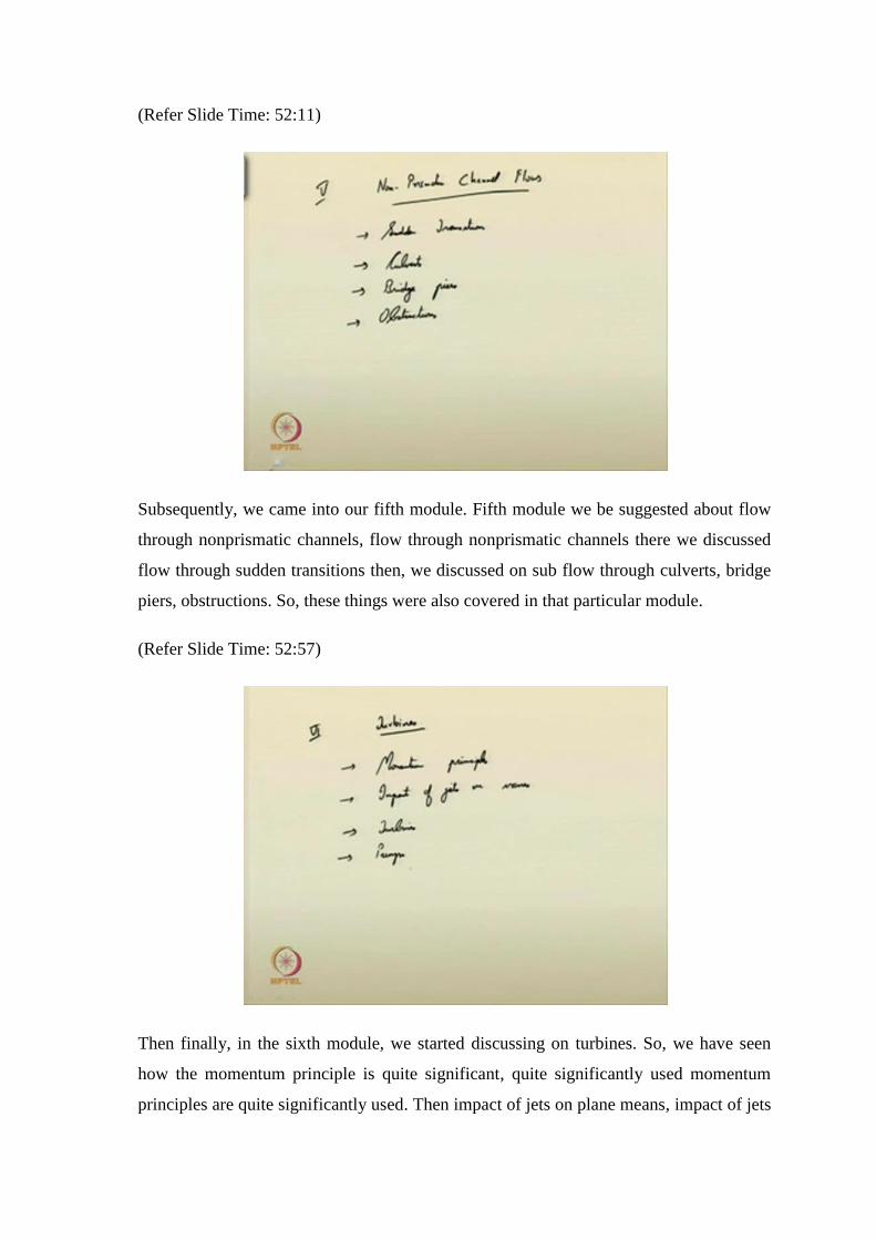
Subsequently, we came into our fifth module. Fifth module we be suggested about flow
through nonprismatic channels, flow through nonprismatic channels there we discussed
flow through sudden transitions then, we discussed on sub flow through culverts, bridge
piers, obstructions. So, these things were also covered in that particular module.
(Refer Slide Time: 52:57)
Then finally, in the sixth module, we started discussing on turbines. So, we have seen
how the momentum principle is quite significant, quite significantly used momentum
principles are quite significantly used. Then impact of jets on plane means, impact of jets
on vanes; this was discussed, then we discussed the types of turbines, types of pumps.
How, what is meant by positive displacement pump, dynamic pump, what is meant by
the... In the turbines, what is meant by reactive turbines and impulsive turbines all those
things we have discussed?
I hope by covering these portions in a brief way, it should have benefit means; it should
be a beneficial thing for you. You might have got some insight into the subject, as well
as some or you may I hope that you are encouraging to further pursue knowledge, on
these subjects and all. Definitely, whatever is covered in this particular course that is not
it is not the entire portion; you can not cover in 40 lectures the entire portions of these
particular subjects and all.
What we intended was we would just briefly cover some of the basic things, or some of
the concepts from which you would like - you will pick it from that location, you will
venture into that subject, either go into the field study or you will go you will deliver,
means, you will go for higher studies or research, do more work and come up with
productive results and all that was that is the objective of this particular lecture series. I
hope it will be beneficial for you or at least it should be an encouraging aspect to you.
Thank you very much.
Keywords:
1. Turbines
2. Reaction turbines, impulse turbines
3. Francis turbine, Pelton wheel turbine, axial flow turbine.
4. Cavitation