Embed Size (px)
Citation preview
COURSE ON
ADVANCED INTERACTION
TECHNIQUES
PROGRAMMING ARDUINO
Luís Carriço
FCUL 2012/13
Sources:
Arduino Hands-on Workshop, SITI, Universidad Lusófona
Arduino Spooky projects
Basic electronics, University Pennsylvania
Beginning Arduino Programming
Getting Started With Arduino
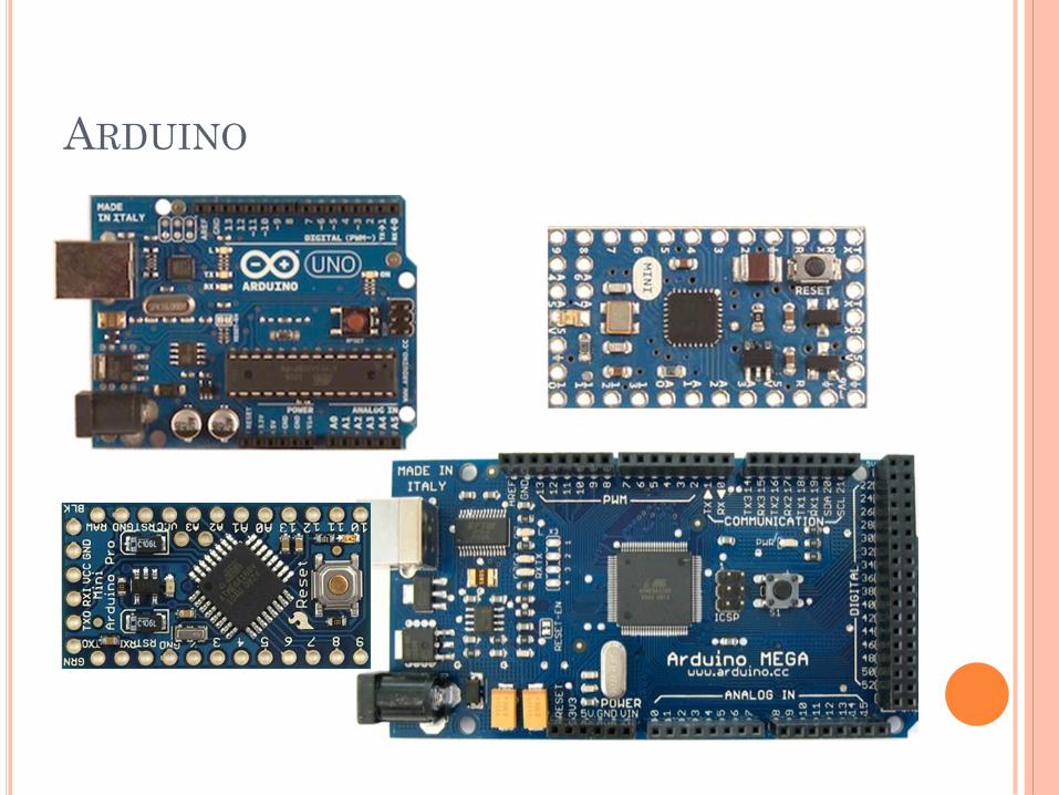
ARDUINO
WHAT IS ARDUINO?
“Arduino is an open-source physical computing
platform based on a simple i/o board and a
development environment that implements the
Processing / Wiring language.
Arduino can be used to develop stand-alone
interactive objects or can be connected to
software on your computer.“
www.arduino.cc, 2006
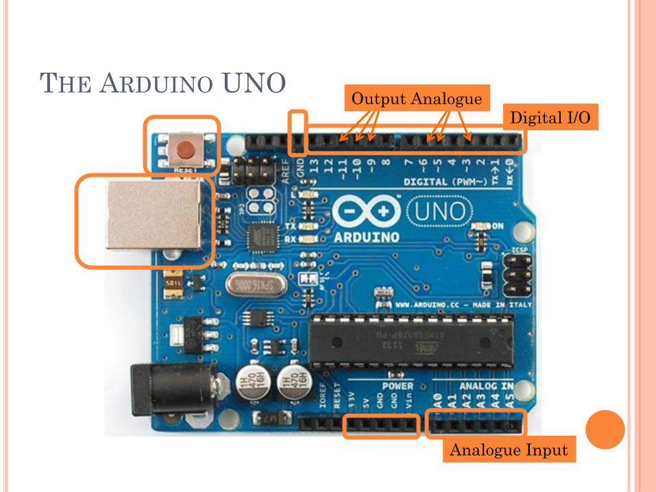
THE ARDUINO UNO Output Analogue
Digital I/O
Analogue Input
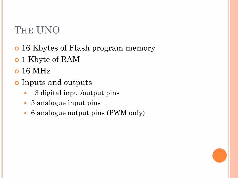
THE UNO
16 Kbytes of Flash program memory
1 Kbyte of RAM
16 MHz
Inputs and outputs
13 digital input/output pins
5 analogue input pins
6 analogue output pins (PWM only)
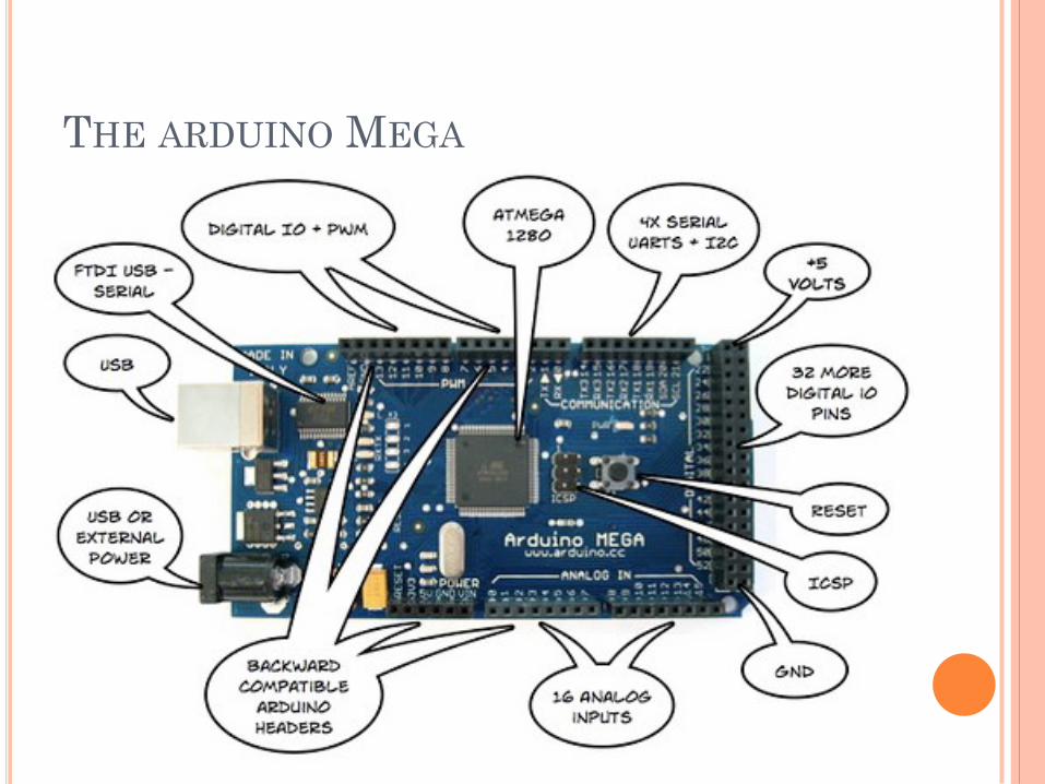
THE ARDUINO MEGA
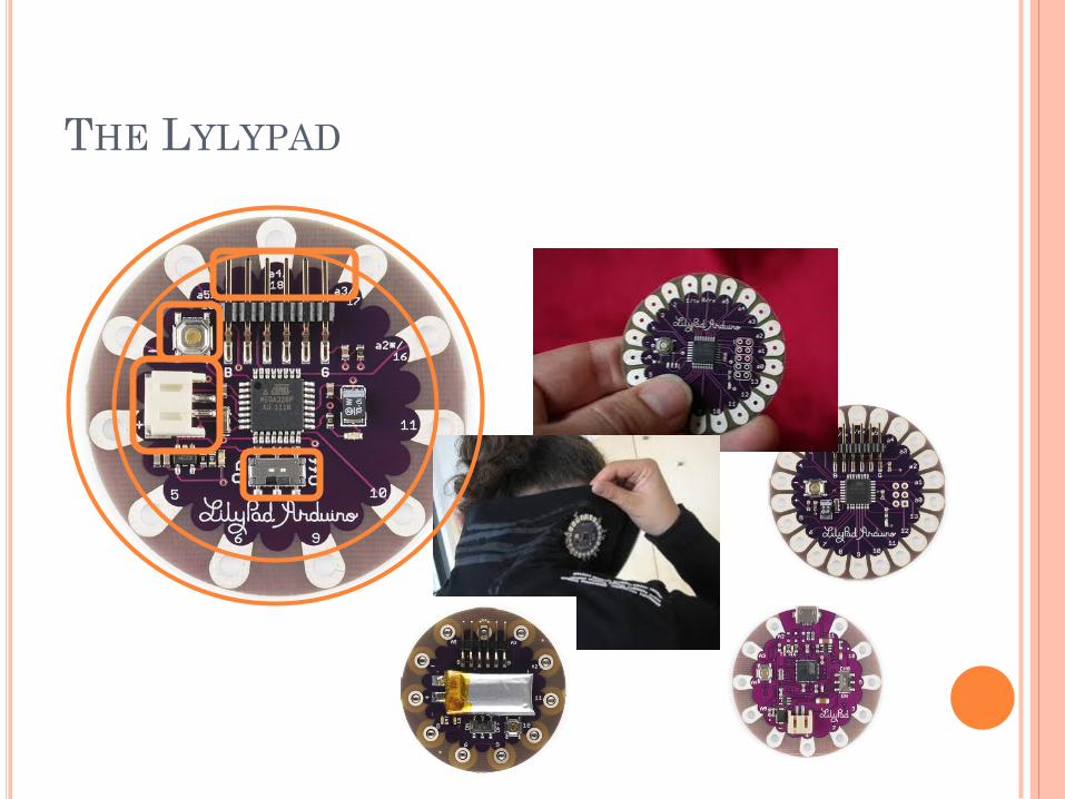
THE LYLYPAD
ELECTRONICS
Basic Concepts
BASIC ELECTRONICS CONCEPTS
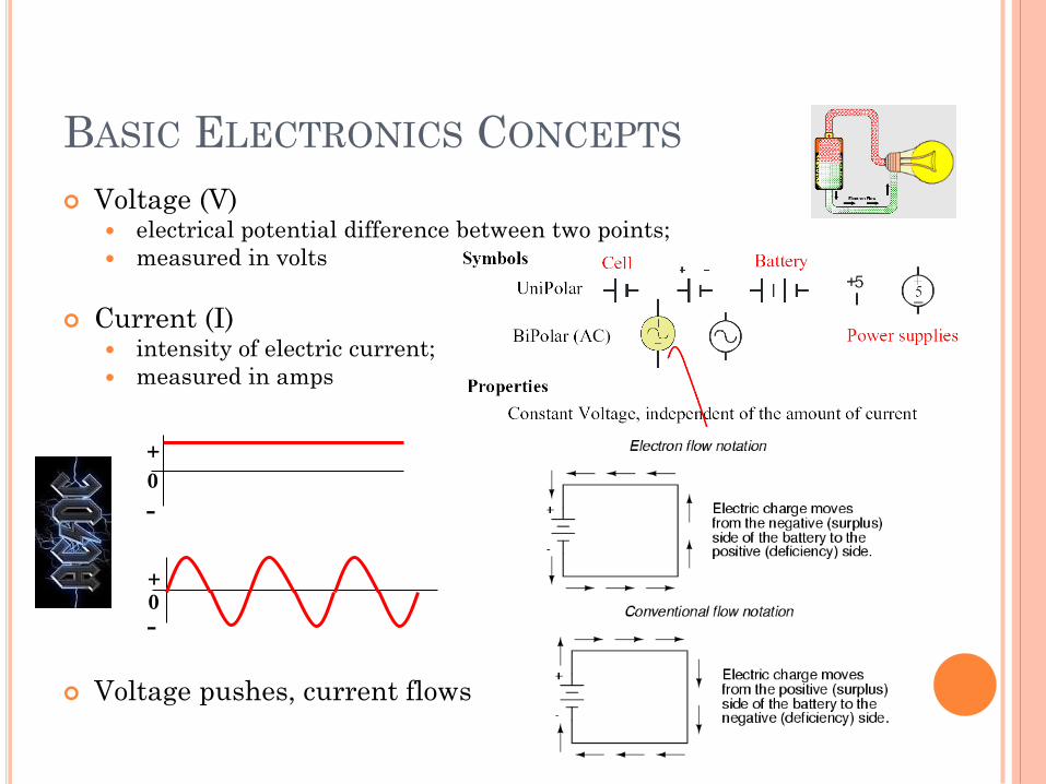
Voltage (V) electrical potential difference between two points;
measured in volts
Current (I) intensity of electric current;
measured in amps
Voltage pushes, current flows
0 +
-
0
+
-
BASIC ELECTRONICS CONCEPTS
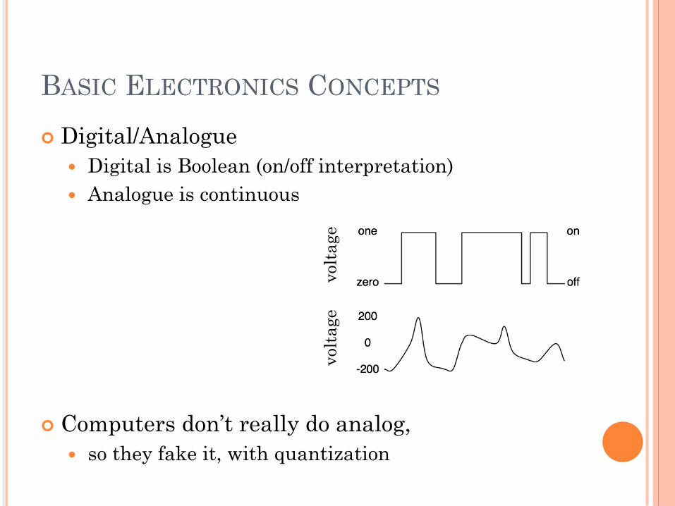
Digital/Analogue
Digital is Boolean (on/off interpretation)
Analogue is continuous
Computers don’t really do analog,
so they fake it, with quantization
volt
age
volt
age

BASIC ELECTRONICS CONCEPTS
Ground

BASIC ELECTRONICS CONCEPTS
Resistance
All materials have a resistance that is
dependent on cross-sectional area, material
type and temperature
Ohms Law
THE MULTIMETER
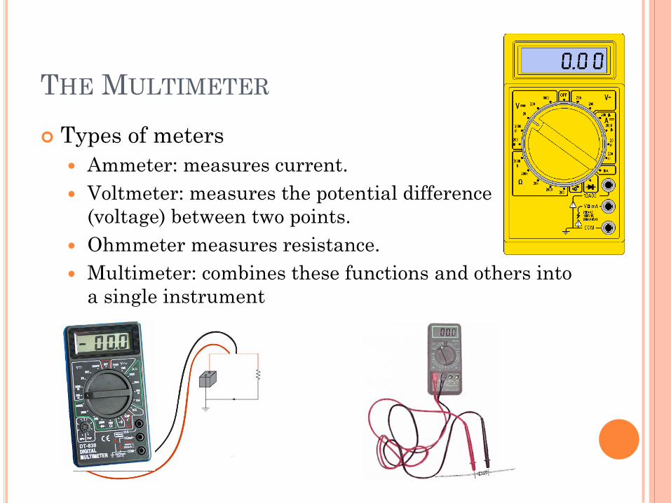
Types of meters
Ammeter: measures current.
Voltmeter: measures the potential difference
(voltage) between two points.
Ohmmeter measures resistance.
Multimeter: combines these functions and others into
a single instrument
DIAGRAMS
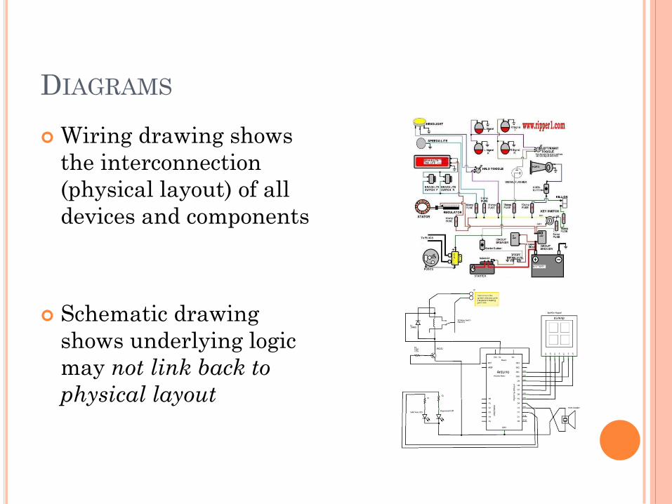
Wiring drawing shows
the interconnection
(physical layout) of all
devices and components
Schematic drawing
shows underlying logic
may not link back to
physical layout

COMPONENTS & SHIELDS
Common Components and Shields
For Arduino Projects
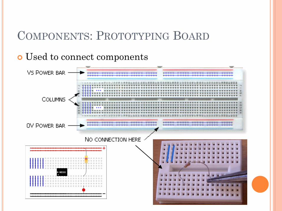
COMPONENTS: PROTOTYPING BOARD
Used to connect components
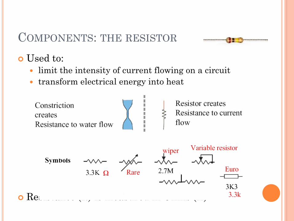
COMPONENTS: THE RESISTOR
Used to:
limit the intensity of current flowing on a circuit
transform electrical energy into heat
Resistance (R) is measured in Ohms (Ω)
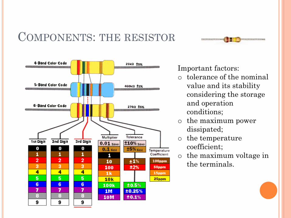
COMPONENTS: THE RESISTOR
Important factors:
o tolerance of the nominal
value and its stability
considering the storage
and operation
conditions;
o the maximum power
dissipated;
o the temperature
coefficient;
o the maximum voltage in
the terminals.

COMPONENTS: THE DIODE
Allows current to pass through in one direction much more easily than the other
Convert alternating current into direct current
Important factors:
Forward voltage drop (Vf)
Peak Inverse Voltage (PIV)
Maximum forward current
Leakage current
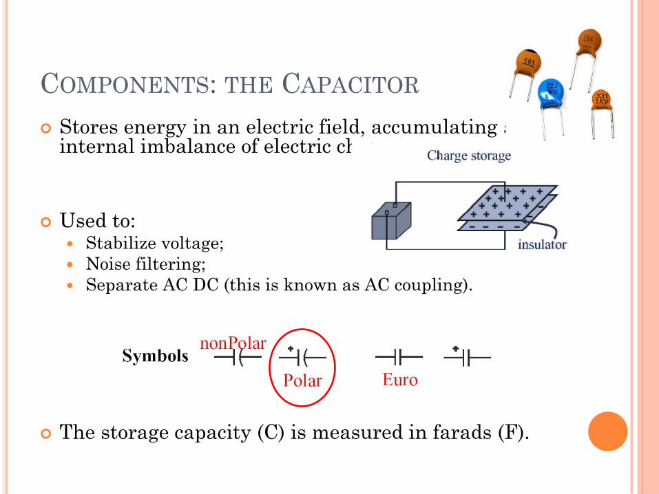
COMPONENTS: THE CAPACITOR
Stores energy in an electric field, accumulating an internal imbalance of electric charge
Used to: Stabilize voltage;
Noise filtering;
Separate AC DC (this is known as AC coupling).
The storage capacity (C) is measured in farads (F).
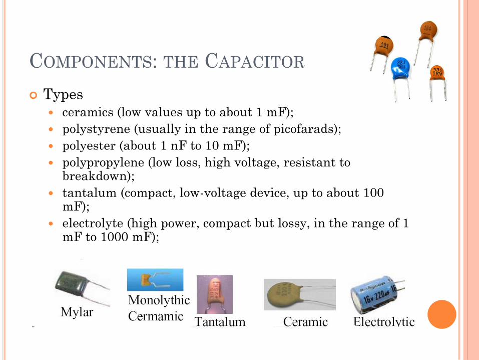
COMPONENTS: THE CAPACITOR
Types
ceramics (low values up to about 1 mF);
polystyrene (usually in the range of picofarads);
polyester (about 1 nF to 10 mF);
polypropylene (low loss, high voltage, resistant to breakdown);
tantalum (compact, low-voltage device, up to about 100 mF);
electrolyte (high power, compact but lossy, in the range of 1 mF to 1000 mF);
.
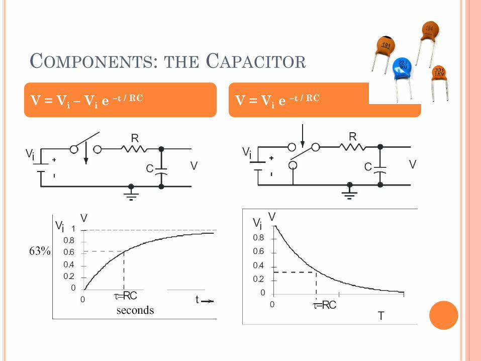
COMPONENTS: THE CAPACITOR
V = Vi – Vi e –t / RC V = Vi e –t / RC
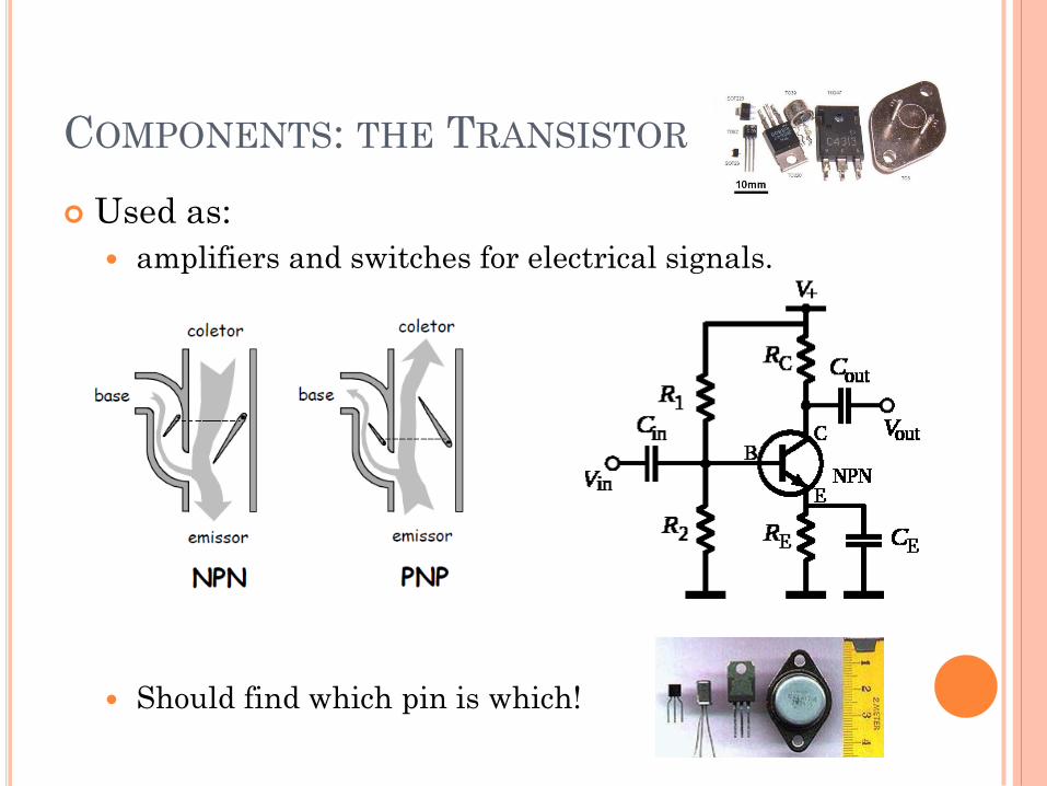
COMPONENTS: THE TRANSISTOR
Used as:
amplifiers and switches for electrical signals.
Should find which pin is which!
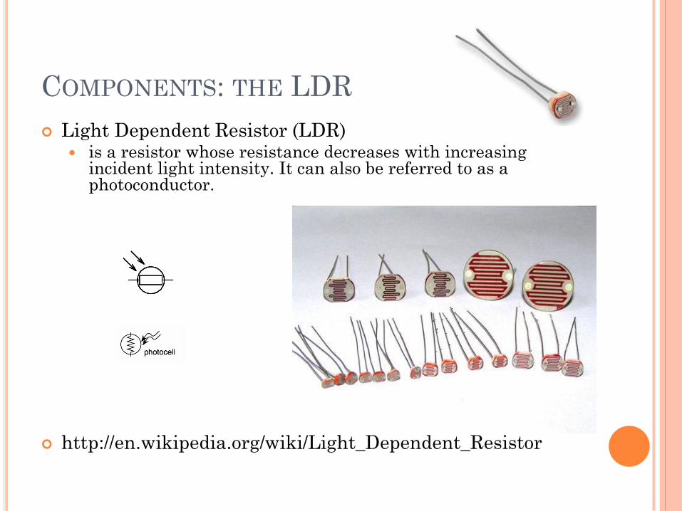
COMPONENTS: THE LDR
Light Dependent Resistor (LDR) is a resistor whose resistance decreases with increasing
incident light intensity. It can also be referred to as a photoconductor.
http://en.wikipedia.org/wiki/Light_Dependent_Resistor
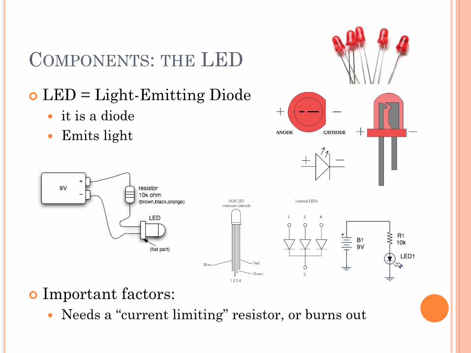
COMPONENTS: THE LED
LED = Light-Emitting Diode
it is a diode
Emits light
Important factors:
Needs a “current limiting” resistor, or burns out
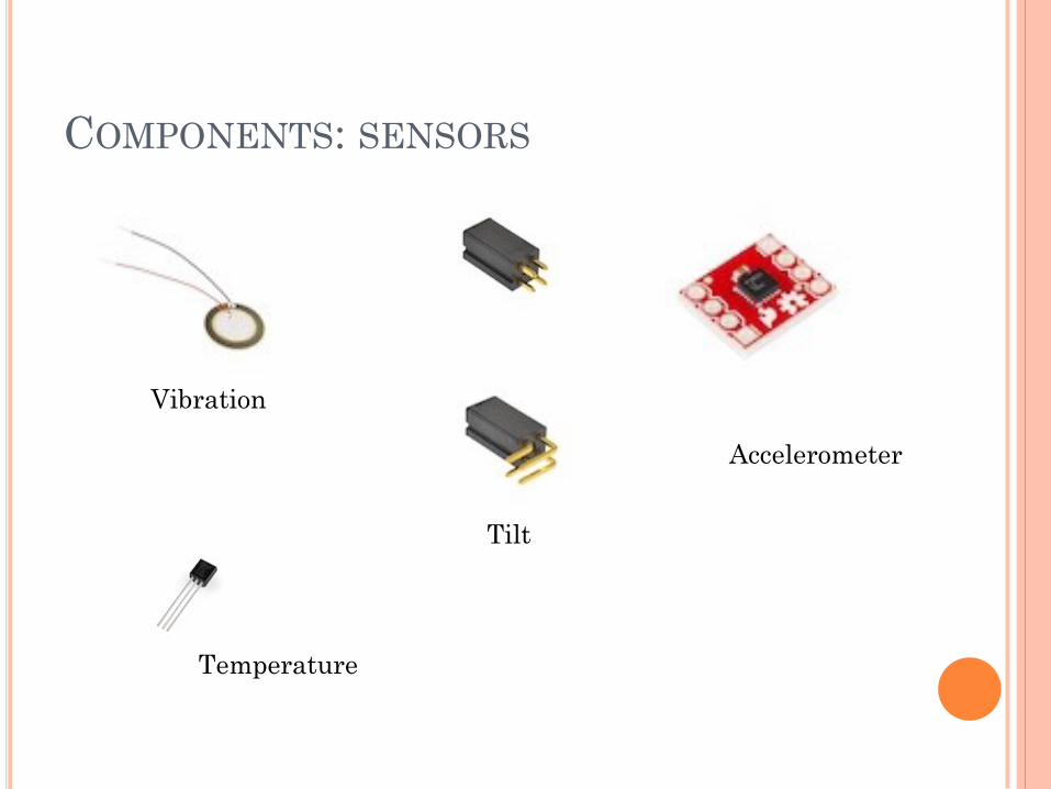
COMPONENTS: SENSORS
Vibration
Tilt
Accelerometer
Temperature
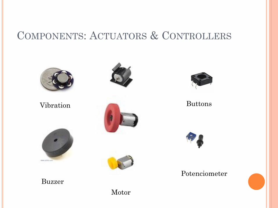
COMPONENTS: ACTUATORS & CONTROLLERS
Vibration
Motor
Buzzer
Buttons
Potenciometer
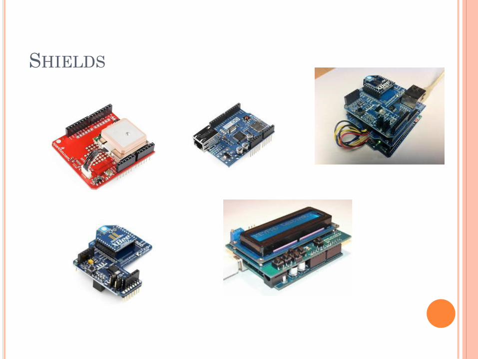
SHIELDS
PROGRAMMING
Programming the Arduino
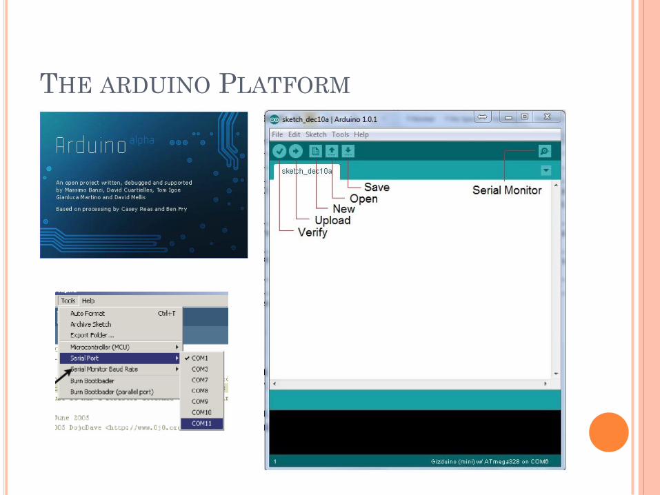
THE ARDUINO PLATFORM
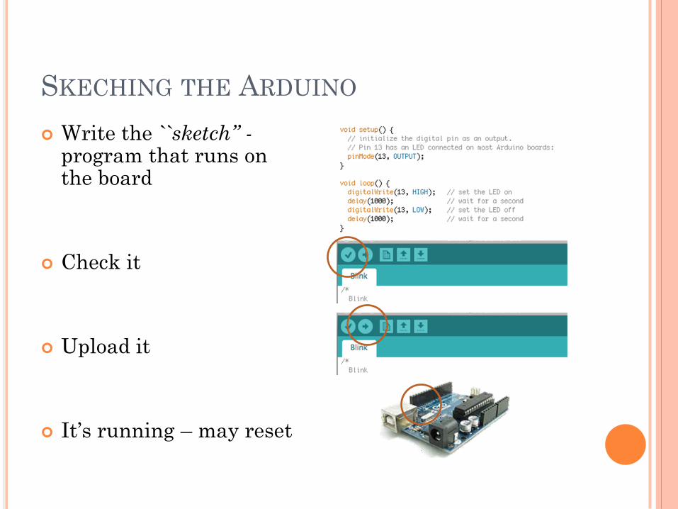
SKECHING THE ARDUINO
Write the ``sketch’’ - program that runs on the board
Check it
Upload it
It’s running – may reset
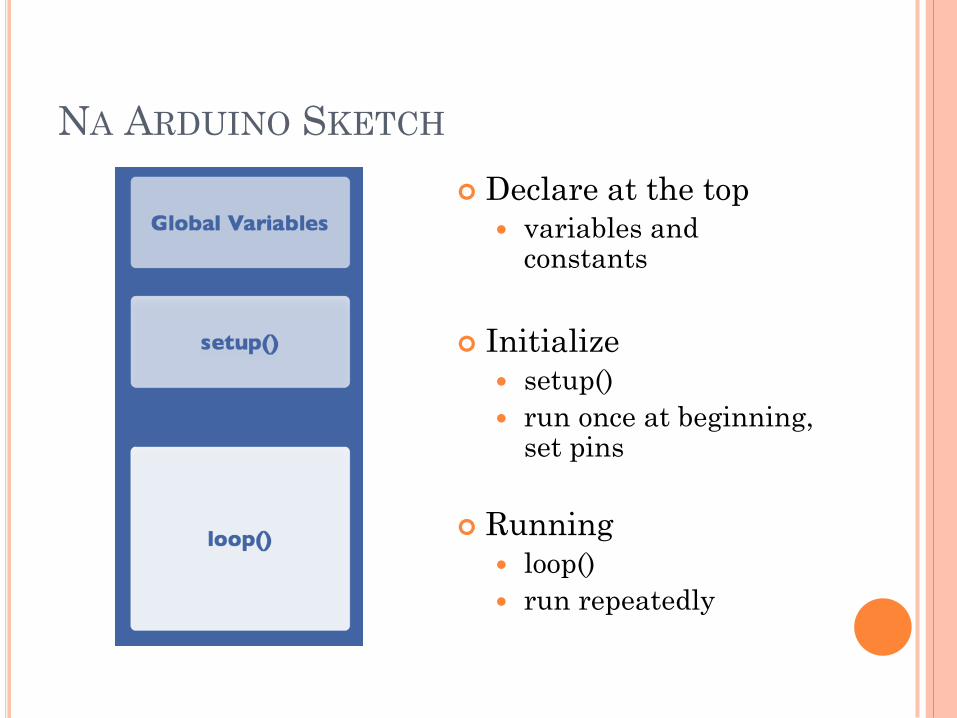
NA ARDUINO SKETCH
Declare at the top
variables and constants
Initialize
setup()
run once at beginning, set pins
Running
loop()
run repeatedly
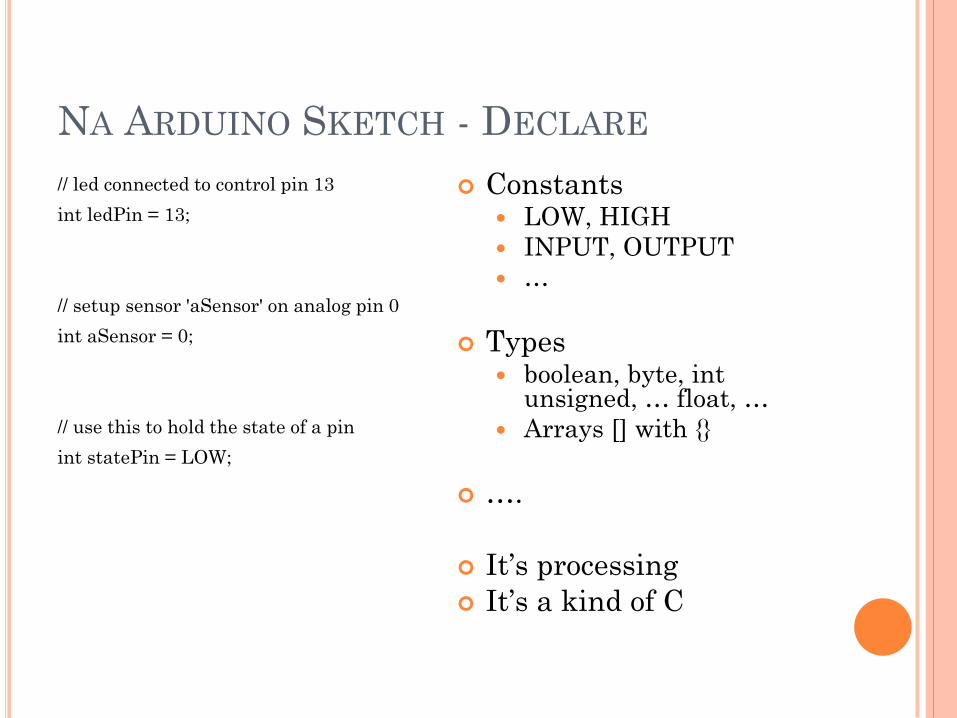
NA ARDUINO SKETCH - DECLARE
// led connected to control pin 13
int ledPin = 13;
// setup sensor 'aSensor' on analog pin 0
int aSensor = 0;
// use this to hold the state of a pin
int statePin = LOW;
Constants LOW, HIGH
INPUT, OUTPUT
…
Types boolean, byte, int
unsigned, … float, …
Arrays [] with
….
It’s processing
It’s a kind of C

NA ARDUINO SKETCH - SETUP
pinMode(ledPin, Output);
// set the pin `ledPin' as an
output
serial.Begin(9600);
// talk to the computer at
// 9600 baud rate
There’s not much
more than this
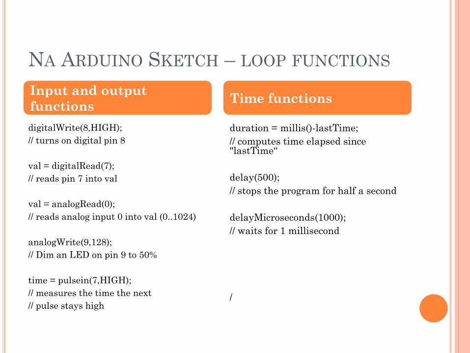
NA ARDUINO SKETCH – LOOP FUNCTIONS
digitalWrite(8,HIGH);
// turns on digital pin 8
val = digitalRead(7);
// reads pin 7 into val
val = analogRead(0);
// reads analog input 0 into val (0..1024)
analogWrite(9,128);
// Dim an LED on pin 9 to 50%
time = pulsein(7,HIGH);
// measures the time the next
// pulse stays high
duration = millis()-lastTime;
// computes time elapsed since "lastTime“
delay(500);
// stops the program for half a second
delayMicroseconds(1000);
// waits for 1 millisecond
/
Input and output
functions Time functions
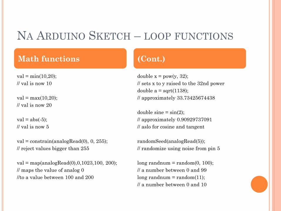
NA ARDUINO SKETCH – LOOP FUNCTIONS
val = min(10,20);
// val is now 10
val = max(10,20);
// val is now 20
val = abs(-5);
// val is now 5
val = constrain(analogRead(0), 0, 255);
// reject values bigger than 255
val = map(analogRead(0),0,1023,100, 200);
// maps the value of analog 0
//to a value between 100 and 200
double x = pow(y, 32);
// sets x to y raised to the 32nd power
double a = sqrt(1138);
// approximately 33.73425674438
double sine = sin(2);
// approximately 0.90929737091
// aslo for cosine and tangent
randomSeed(analogRead(5));
// randomize using noise from pin 5
long randnum = random(0, 100);
// a number between 0 and 99
long randnum = random(11);
// a number between 0 and 10
Math functions (Cont.)
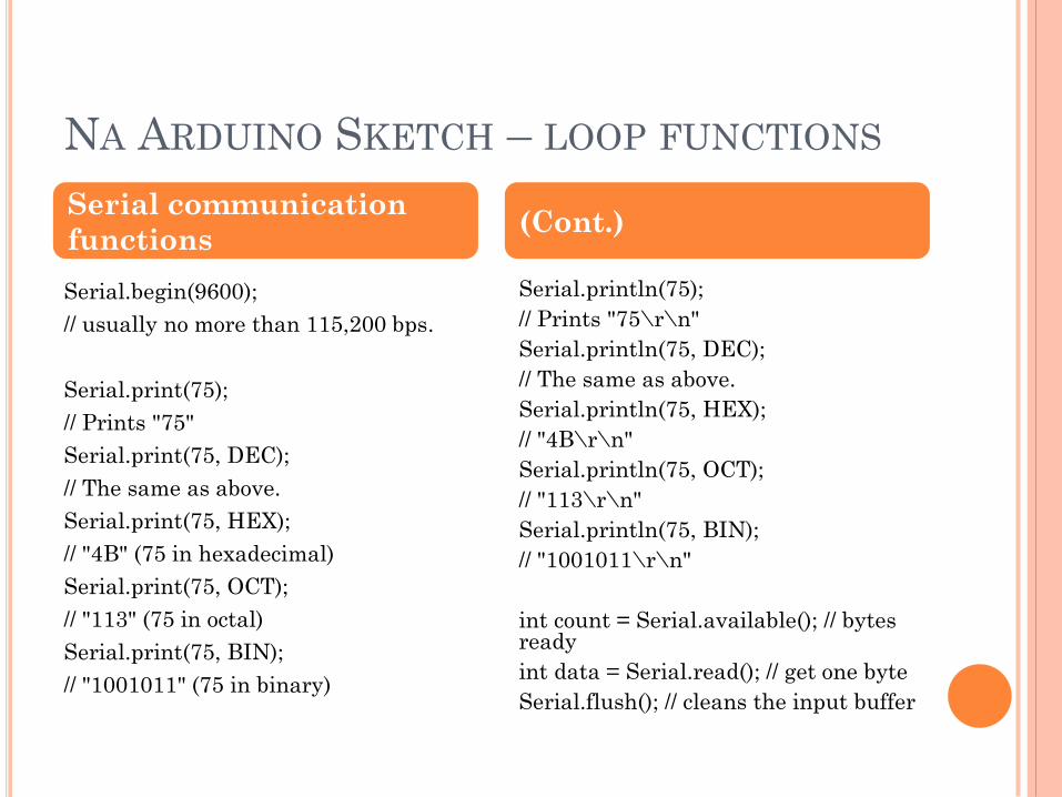
NA ARDUINO SKETCH – LOOP FUNCTIONS
Serial.begin(9600);
// usually no more than 115,200 bps.
Serial.print(75);
// Prints "75"
Serial.print(75, DEC);
// The same as above.
Serial.print(75, HEX);
// "4B" (75 in hexadecimal)
Serial.print(75, OCT);
// "113" (75 in octal)
Serial.print(75, BIN);
// "1001011" (75 in binary)
Serial.println(75);
// Prints "75\r\n"
Serial.println(75, DEC);
// The same as above.
Serial.println(75, HEX);
// "4B\r\n"
Serial.println(75, OCT);
// "113\r\n"
Serial.println(75, BIN);
// "1001011\r\n"
int count = Serial.available(); // bytes ready
int data = Serial.read(); // get one byte
Serial.flush(); // cleans the input buffer
Serial communication
functions (Cont.)
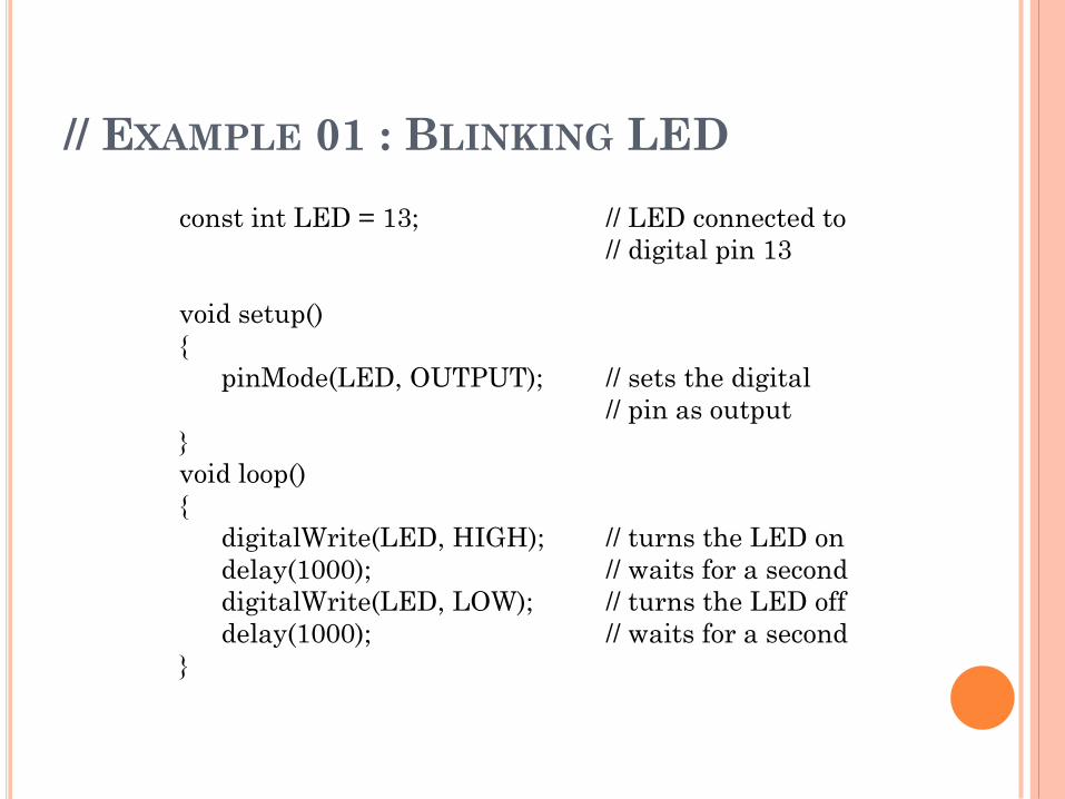
// EXAMPLE 01 : BLINKING LED
const int LED = 13; // LED connected to
// digital pin 13
void setup()
pinMode(LED, OUTPUT); // sets the digital
// pin as output
void loop()
digitalWrite(LED, HIGH); // turns the LED on
delay(1000); // waits for a second
digitalWrite(LED, LOW); // turns the LED off
delay(1000); // waits for a second
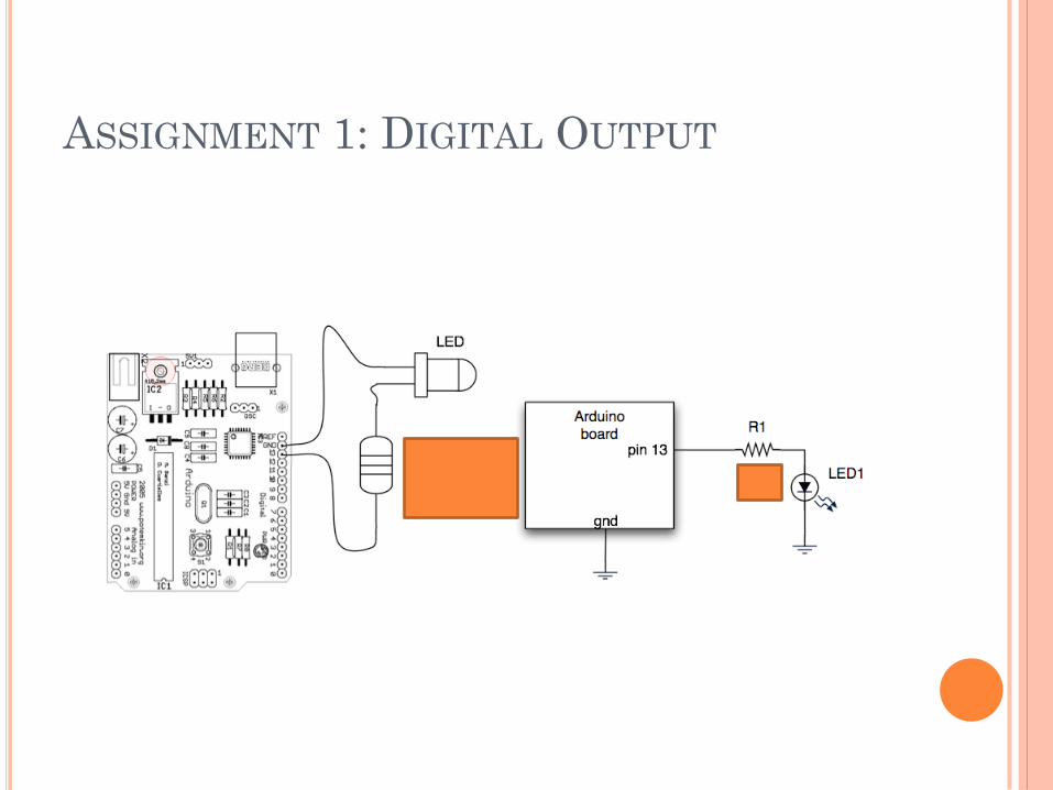
ASSIGNMENT 1: DIGITAL OUTPUT
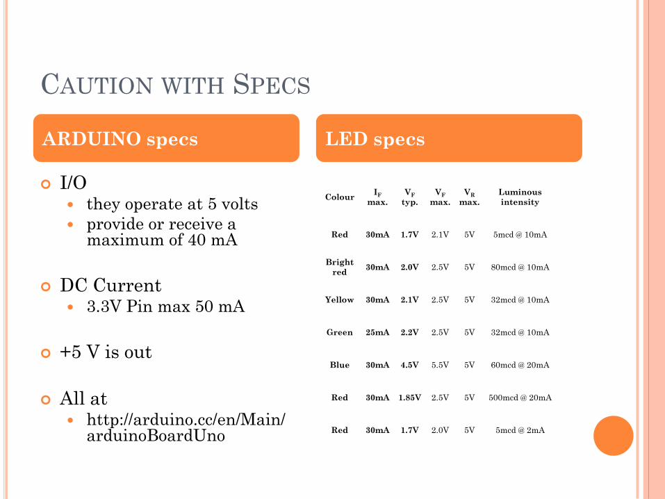
CAUTION WITH SPECS
I/O they operate at 5 volts
provide or receive a maximum of 40 mA
DC Current 3.3V Pin max 50 mA
+5 V is out
All at http://arduino.cc/en/Main/
arduinoBoardUno
Colour IF
max.
VF
typ.
VF
max.
VR
max.
Luminous
intensity
Red 30mA 1.7V 2.1V 5V 5mcd @ 10mA
Bright
red 30mA 2.0V 2.5V 5V 80mcd @ 10mA
Yellow 30mA 2.1V 2.5V 5V 32mcd @ 10mA
Green 25mA 2.2V 2.5V 5V 32mcd @ 10mA
Blue 30mA 4.5V 5.5V 5V 60mcd @ 20mA
Red 30mA 1.85V 2.5V 5V 500mcd @ 20mA
Red 30mA 1.7V 2.0V 5V 5mcd @ 2mA
ARDUINO specs LED specs
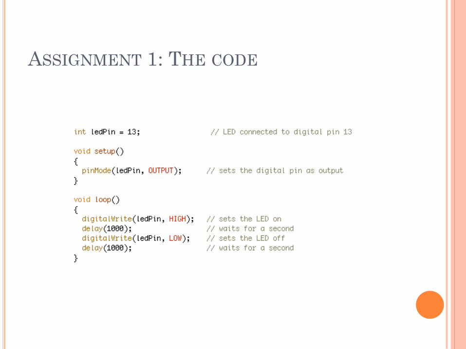
ASSIGNMENT 1: THE CODE
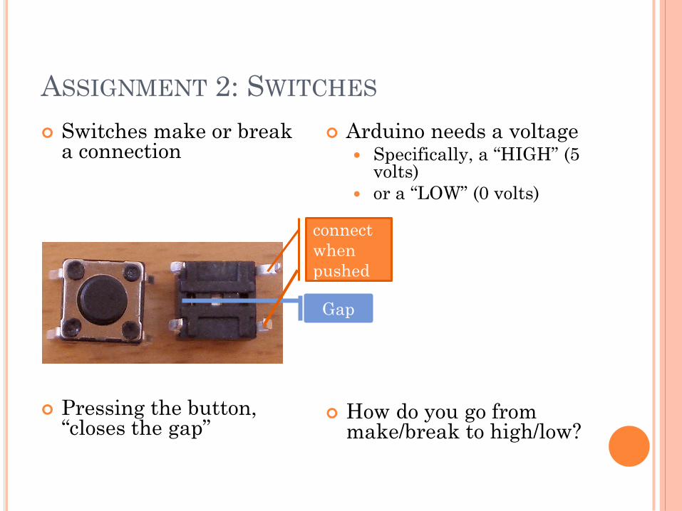
ASSIGNMENT 2: SWITCHES
Switches make or break a connection
Pressing the button, “closes the gap”
Arduino needs a voltage Specifically, a “HIGH” (5
volts)
or a “LOW” (0 volts)
How do you go from make/break to high/low?
Gap
connect
when
pushed
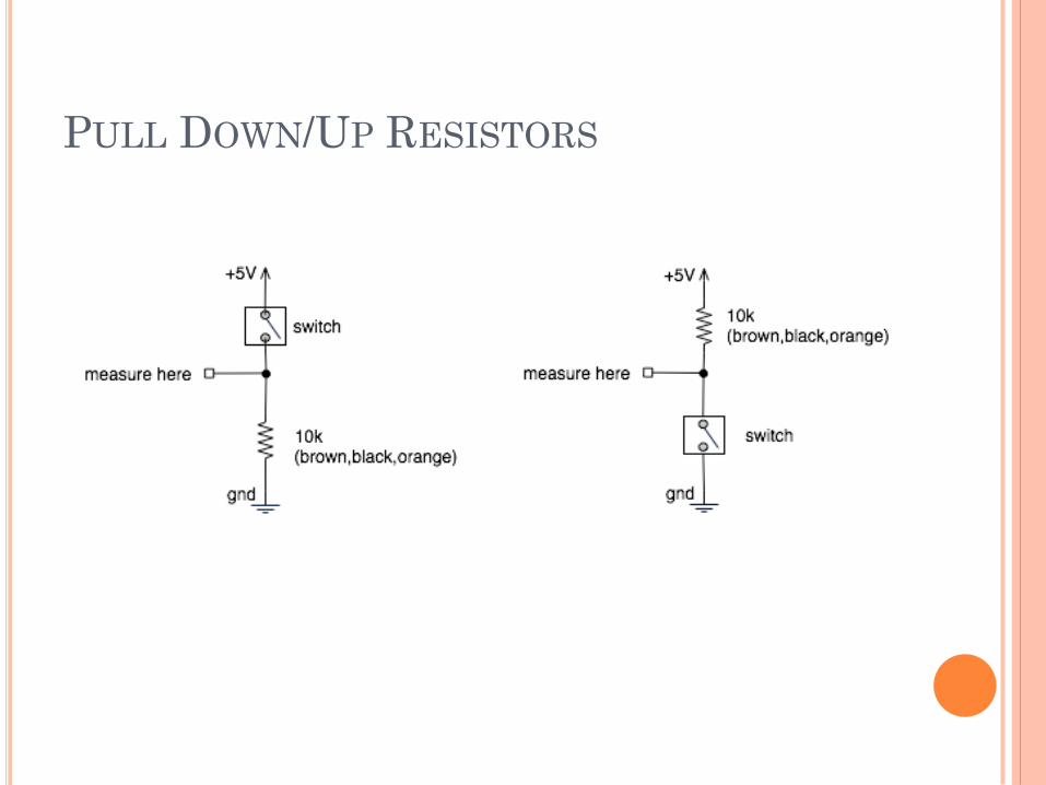
PULL DOWN/UP RESISTORS
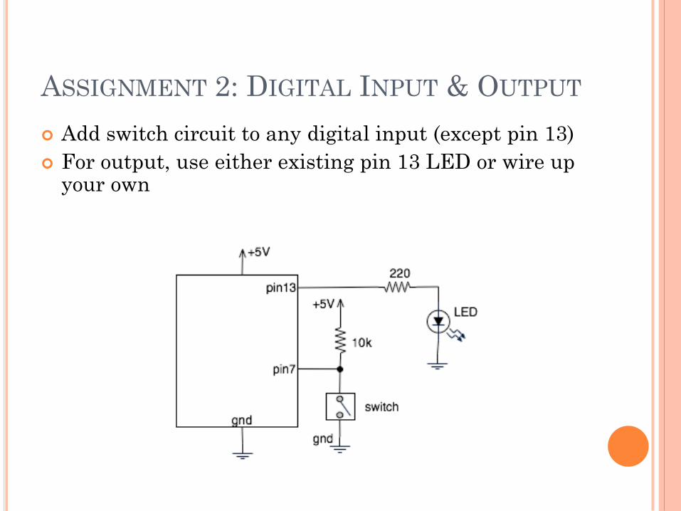
ASSIGNMENT 2: DIGITAL INPUT & OUTPUT
Add switch circuit to any digital input (except pin 13)
For output, use either existing pin 13 LED or wire up your own
.
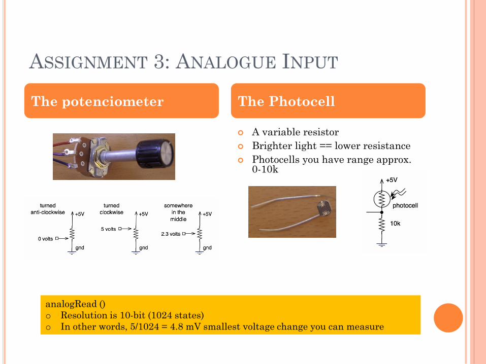
ASSIGNMENT 3: ANALOGUE INPUT
A variable resistor
Brighter light == lower resistance
Photocells you have range approx. 0-10k
.
The potenciometer The Photocell
analogRead ()
o Resolution is 10-bit (1024 states)
o In other words, 5/1024 = 4.8 mV smallest voltage change you can measure
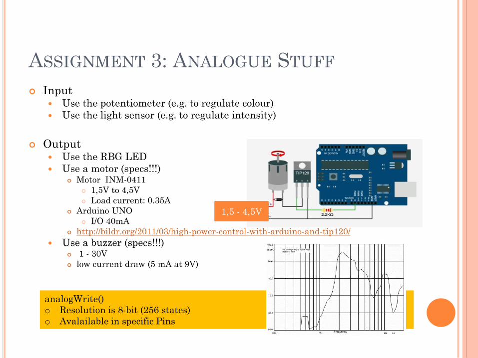
ASSIGNMENT 3: ANALOGUE STUFF
Input Use the potentiometer (e.g. to regulate colour)
Use the light sensor (e.g. to regulate intensity)
Output Use the RBG LED
Use a motor (specs!!!) Motor INM-0411
1,5V to 4,5V
Load current: 0.35A
Arduino UNO
I/O 40mA
http://bildr.org/2011/03/high-power-control-with-arduino-and-tip120/
Use a buzzer (specs!!!) 1 - 30V
low current draw (5 mA at 9V)
.
analogWrite()
o Resolution is 8-bit (256 states)
o Avalailable in specific Pins
1,5 - 4,5V
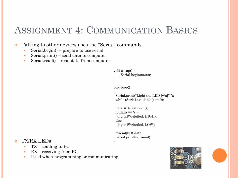
ASSIGNMENT 4: COMMUNICATION BASICS
Talking to other devices uses the “Serial” commands Serial.begin() – prepare to use serial
Serial.print() – send data to computer
Serial.read() – read data from computer
TX/RX LEDs TX – sending to PC
RX – receiving from PC
Used when programming or communicating
void setup()
Serial.begin(9600);
void loop()
Serial.print("Light the LED [y/n]? ");
while (Serial.available() == 0);
data = Serial.read();
if (data == 'y')
digitalWrite(led, HIGH);
else
digitalWrite(led, LOW);
tosend[0] = data;
Serial.println(tosend);
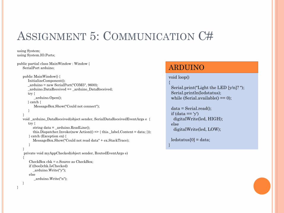
ASSIGNMENT 5: COMMUNICATION C# using System;
using System.IO.Ports;
public partial class MainWindow : Window
SerialPort arduino;
public MainWindow()
InitializeComponent();
_arduino = new SerialPort("COM5", 9600);
_arduino.DataReceived += _arduino_DataReceived;
try
_arduino.Open();
catch
MessageBox.Show("Could not connect");
void _arduino_DataReceived(object sender, SerialDataReceivedEventArgs e
try
string data = _arduino.ReadLine();
this.Dispatcher.Invoke(new Action(() => this._label.Content = data; ));
catch (Exception ex)
MessageBox.Show("Could not read data" + ex.StackTrace);
private void myAppChecked(object sender, RoutedEventArgs e)
CheckBox chk = e.Source as CheckBox;
if ((bool)chk.IsChecked)
_arduino.Write("y");
else
_arduino.Write("n");
void loop()
Serial.print("Light the LED [y/n]? ");
Serial.println(ledstatus);
while (Serial.available() == 0);
data = Serial.read();
if (data == 'y')
digitalWrite(led, HIGH);
else
digitalWrite(led, LOW);
ledstatus[0] = data;
ARDUINO