Embed Size (px)
Citation preview

g imagination at work
KEY BENEFITS
• GE patented, dual input light and pressure wave sensors for fast, reliable arc flash detection
• Arc flash detection and trip initiation in as fast as 1ms to reduce equipment damage and increase system uptime
• Independent device provides continuous, always on, operation to maximize equipment protection
• Continuous health monitoring of optical sensors, fiber cables, and control unit to ensure reliable operation
• Direct connection to breaker trip circuit using solid state output relays, for increased operating speed
• Multi-stage detection for reduced nuisance tripping with optional external current supervision input
• Simplified installation and configuration with sensor auto-calibration and no requirement for additional setup software
• Up to 5 arc flash sensors per unit provides optimized coverage for Switchgear compartments
• Multiple unit connectivity and transfer trip capability to ensure optimized coverage for large applications
• No requirement to install additional CT’s reducing time and costs associated with installation and commissioning
• DIN rail mounted for easy installation and reduced commissioning time
• Suitable for both new and retrofit applications
• Arc flash detection system for medium voltage applications (switchgear and motor control centers)
• Applications requiring arc flash mitigation
• Suitable for new and existing retrofit applications
• GE patented, high-speed arc flash system utilizing light and pressure wave detection technology
• Stand-alone unit providing continuous operation, 24/7
• Continuous self-supervision (health monitoring) of sensors, fiber cables, and arc flash relay with trouble indication
• External current supervision from IOC device
• Up to five arc flash sensors per relay for detection in multiple locations within switchgear
• Five solid state output relays for fast trip initiation
• Six digital inputs with transfer trip capability for cascading applications
• Arc flash sensor auto-calibration
• Three LEDs for indication for Status, Trip, and Trouble
• Local and remote reset capability
• DIN Rail mounting
• Slide switches and rotary dial for device setup
• No setup software required
• Operating temperature range from -40°C to +60°C
FEATURES
APPLICATIONS
Advanced Light & Pressure Arc Flash Detection System
MultilinA60™
2 GEDigitalEnergy.com
OverviewAn arc flash event is the sudden release of electrical energy through the air. The resulting forces can produce temperatures up to 35,000°F, in less than one thousandths of a second, causing copper to turn into plasma expanding by 67,000 times. The arc event remains as long as there is enough power to maintain the short circuit . With these type of extreme events, fast , reliable arc flash detection is critical for the power and process industries in order to avoid significant damage to equipment and reduce the repair and replacement costs, as well as downtime of the power system.
In an arc flash event , the amount of energy generated is a direct function of time so, when considering arc flash detection or mitigation solutions, every millisecond counts.
The Multilin A60 Arc Flash System utilizes a unique sensing method that detects both light and pressurized sound signals that occur during an arc flash event, enabling more reliable and faster operating times to reduce the total arc energy generated. Utilizing a patented arc flash sensing method, the Multilin A60 is able to reliably detect an arc flash event in as fast as 1 msec (when compared to not having any arc flash detection device).
As an independent arc flash detection device, the Multilin A60 Arc Flash System provides wide-ranging, scalable arc flash detection for medium voltage switchgear and motor control center applications.
Advanced Sensor Technology
Light and pressure wave arc flash detection
The Multilin A60 Arc Flash System utilizes GE’s patented light and pressure signal fiber sensor to ensure fast and reliable protection against arcing events.
Based on a known time relationship between the speed of light and sound, (pressure wave), GE’s patented sensor is able to detect and issue a trigger signal to clear the fault in under 2 milliseconds – significantly reducing incident energy from an arc flash event.
Specifically, the sensor head detects these two key factors (light and pressure wave) using LEDs, bare fiber and a membrane.
The light fiber picks up the flash of light from the bare fiber in the sensor and transmits that to the Multilin A60. On a second fiber an LED emits light. This light is transported through the fiber and is reflected back by the diaphragm, and collected by the same fiber back to the main unit .During an arc flash event, the diaphragm vibrates due to the pressurized sound wave creating a signature which is recognized by the Multilin A60. It is this unique combination of light and pressure wave detection that ensures reliable and fast detection of an arc flash event.
To ensure optimal coverage, the Multilin A60 supports up to five sensors per unit providing optimal coverage in a typical two-high medium voltage switchgear section. To cover a larger area or for multi-section applications, Multilin A60’s may be daisy chained together.
Inputs & OutputsThe Multilin A60 includes six isolated 24V dry inputs. Digital inputs are used for ‘daisy chaining’ multiple relays together or for remote control.
The Multilin A60 includes five solid state output relays which may be connected directly to a fast disconnect device, such as a circuit breaker or switch for trip initiation and/or to other devices for signaling purposes. Utilizing solid state output contacts, it ensures very fast response and operating times, reducing total arc flash energy. The Multilin A60 also includes one alarm output that provides remote indication of an arc flash event.
Easy to Install & Configure
Well suited for both new and existing applications
As a stand-alone unit , the Multilin A60 relay is DIN rail mountable and should be mounted inside the control cabinet of the medium voltage switchgear or motor control center, making it suitable for both new and retrofit applications.
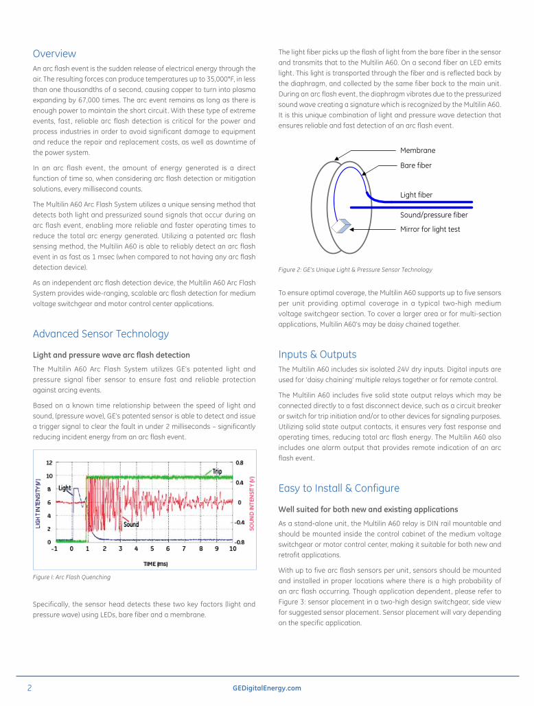
With up to five arc flash sensors per unit , sensors should be mounted and installed in proper locations where there is a high probability of an arc flash occurring. Though application dependent, please refer to Figure 3: sensor placement in a two-high design switchgear, side view for suggested sensor placement. Sensor placement will vary depending on the specific application.
Figure I: Arc Flash Quenching
Figure 2: GE’s Unique Light & Pressure Sensor Technology
Membrane
Light fiber
Sound/pressure fiber
Bare fiber
Mirror for light test
3GEDigitalEnergy.com
As the Multilin A60 utilizes both light and pressure to detect an arc flash condition, installation and wiring of external CT’s is not required. An external current supervision from a separate Instantaneous Over Current (IOC) device may be used and connected as a contact input on the Multilin A60 for enhanced security and mitigation of nuisance tripping.
Calibration & Testing
The Multilin A60 provides an auto-calibration function for the sensors, reducing total commissioning and testing time. Once installed and powered, the device will first run in calibration mode. This mode sets the thresholds for both the light and pressurized sound, based on surrounding ambient conditions. As surrounding conditions may change, the Multilin A60 may be re-calibrated at anytime.
Enhanced Diagnostics
Constant self-monitoring and diagnostics to ensure reliable operation
The Multilin A60 has a built-in self-test feature that runs every second during normal operating mode. This unique feature monitors the health of the sensors, the full length of the fiber cables, and the unit itself, eliminating the need for periodic testing and additional test equipment.
An LED on the unit is used to indicate the health of the sensor and its connection to the unit . Using the alarm output relay, remote health status indication is also provided.
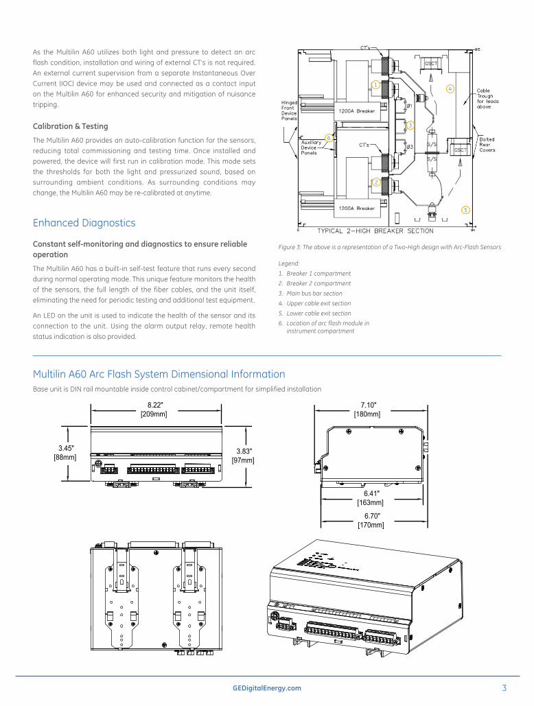
Multilin A60 Arc Flash System Dimensional InformationBase unit is DIN rail mountable inside control cabinet/compartment for simplified installation
A1 06/01/12 N/A A.Z N.N FIRST RELEASE
N.NA.ZA.Z 06/01/12
06/01/1206/01/12
DFD
877700X:\DRAFTING\ILLUSTRATOR NTS N/A
877700
UNIT OUTLINE FOR MANUALAFD
SHEET 1 OF 1A1
215 ANDERSON AVE.MARKHAM, ON, CANADA, L6E 1B3
TEL: (905)294-6222 FAX: (905)201-2098INTERNET: http://www.gedigitalenergy.com/multilin/
SIZE DRAWING REV
SCALE: PART No:
SIGNATURES DATE
MODEL
CHECKED
WHERE USED
DRAWING FILE:
FILE LOCATION:
SOFTWARE TOOL:CRITICAL TO QUALITYCHARACTERISTIC
FINISH
FRACTIONS ±
TOLERANCE ON:1 PL DECIMALS ± 0.12 PL DECIMALS ± 0.013 PL DECIMALS ± 0.005
ANGLES ± 1.0
UNLESS OTHERWISESPECIFIED IN DRAWING
DIMENSIONS ARE IN INCHES [mm]
APPLIED PRACTICESFOR ADDITIONAL INFO REFER TO:
TITLE
Digital EnergyMultilin
SIZE DRAWING REV
ASCALE:
DETAIL
1 PL DECIMALS ± 0.1
ANGLES ± 1.0
GE PROPRIETARY AND CONFIDENTIAL INFORMATIONThis document is the property of General Electric Company ("GE") and contains proprietary information of GE. This document is loaned on the
express condition that neither it nor the information contained therein shall be disclosed to others without the express written consent of GE
Digital Energy, and that the information shall be used by the recipient only as approved expressly by GE Digital Energy. This document shall be returned to GE upon its request. This document may be subject to
certain restrictions under U.S. export control laws and regulations.
REV EC0# DWN APPDATE
REVISIONS
DESCRIPTION
THIRD ANGLE PROJECTIONTHIRD ANGLE PROJECTION
NOTE:
1. REFERENCE DRAWING 877450A1
3.45" [88mm]
3.83" [97mm]
6.70" [170mm]
6.41" [163mm]
7.10" [180mm]
8.22" [209mm]
877700A1
Figure 3: The above is a representation of a Two-High design with Arc-Flash Sensors
Legend:
1. Breaker 1 compartment
2. Breaker 2 compartment
3. Main bus bar section
4. Upper cable exit section
5. Lower cable exit section
6. Location of arc flash module in instrument compartment
1
3
5
2
4
6
4 GEDigitalEnergy.com
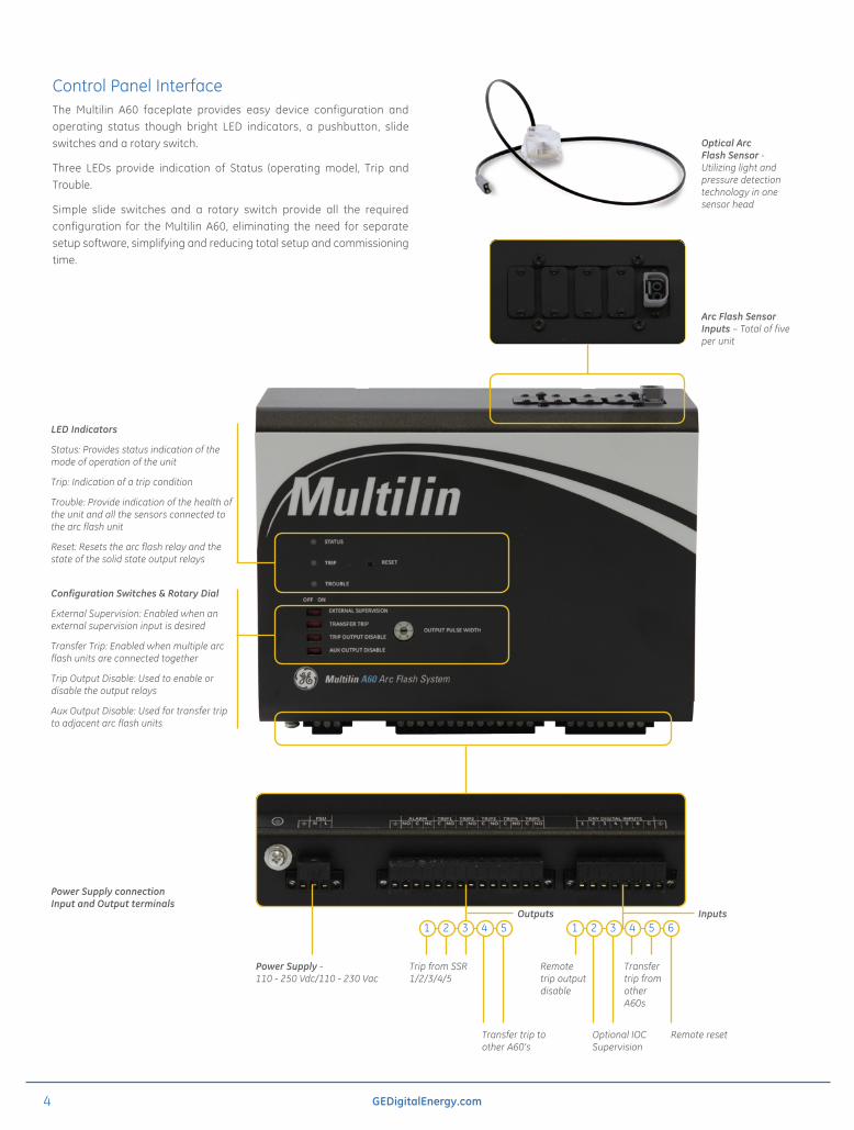
Control Panel InterfaceThe Multilin A60 faceplate provides easy device configuration and operating status though bright LED indicators, a pushbutton, slide switches and a rotary switch.
Three LEDs provide indication of Status (operating mode), Trip and Trouble.
Simple slide switches and a rotary switch provide all the required configuration for the Multilin A60, eliminating the need for separate setup software, simplifying and reducing total setup and commissioning time.
Arc Flash Sensor Inputs – Total of five per unit
Power Supply connection Input and Output terminals
InputsOutputs
LED Indicators
Status: Provides status indication of the mode of operation of the unit
Trip: Indication of a trip condition
Trouble: Provide indication of the health of the unit and all the sensors connected to the arc flash unit
Reset: Resets the arc flash relay and the state of the solid state output relays
Configuration Switches & Rotary Dial
External Supervision: Enabled when an external supervision input is desired
Transfer Trip: Enabled when multiple arc flash units are connected together
Trip Output Disable: Used to enable or disable the output relays
Aux Output Disable: Used for transfer trip to adjacent arc flash units
Optical Arc Flash Sensor - Utilizing light and pressure detection technology in one sensor head
Power Supply - 110 - 250 Vdc/110 - 230 Vac
Trip from SSR 1/2/3/4/5
Transfer trip to other A60’s
Optional IOC Supervision
Remote reset
Transfer trip from other A60s
Remote trip output disable
2 4 1 3 5 1 3 5 2 4 6
5GEDigitalEnergy.com
CB CB
CB
SSR 1
Contact Input4 or 5
Contact Input 1
Contact Input 6PowerSupply
CB
CB
SSR 4
Contact Input 1
Contact Input 6PowerSupply
AFS 1
AFS 2
AFS = Arc flash systemSSR = Solid-state relayCB = Circuit breaker
= Sensor
Transformer
CB CB
CB
AFS = Arc flash systemSSR = Solid-state relayCB = Circuit breaker
= Sensor
CB
SSR 4
Contact Input 1
Contact Input 6PowerSupply
AFS 3
SSR 4
Contact Input 1
Contact Input 6PowerSupply
AFS 2
Contact Input4 or 5
Contact Input4 or 5
SSR 1
Contact Input 1
Contact Input 6PowerSupply
AFS 1
Transformer
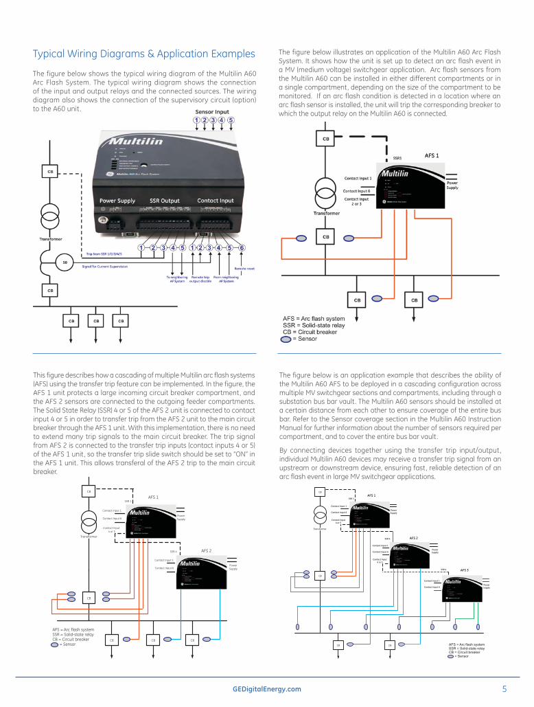
Typical Wiring Diagrams & Application Examples
The figure below shows the typical wiring diagram of the Multilin A60 Arc Flash System. The typical wiring diagram shows the connection of the input and output relays and the connected sources. The wiring diagram also shows the connection of the supervisory circuit (option) to the A60 unit .
This figure describes how a cascading of multiple Multilin arc flash systems (AFS) using the transfer trip feature can be implemented. In the figure, the AFS 1 unit protects a large incoming circuit breaker compartment, and the AFS 2 sensors are connected to the outgoing feeder compartments. The Solid State Relay (SSR) 4 or 5 of the AFS 2 unit is connected to contact input 4 or 5 in order to transfer trip from the AFS 2 unit to the main circuit breaker through the AFS 1 unit. With this implementation, there is no need to extend many trip signals to the main circuit breaker. The trip signal from AFS 2 is connected to the transfer trip inputs (contact inputs 4 or 5) of the AFS 1 unit, so the transfer trip slide switch should be set to “ON” in the AFS 1 unit. This allows transferal of the AFS 2 trip to the main circuit breaker.
The figure below is an application example that describes the ability of the Multilin A60 AFS to be deployed in a cascading configuration across multiple MV switchgear sections and compartments, including through a substation bus bar vault. The Multilin A60 sensors should be installed at a certain distance from each other to ensure coverage of the entire bus bar. Refer to the Sensor coverage section in the Multilin A60 Instruction Manual for further information about the number of sensors required per compartment, and to cover the entire bus bar vault.
By connecting devices together using the transfer trip input/output, individual Multilin A60 devices may receive a transfer trip signal from an upstream or downstream device, ensuring fast, reliable detection of an arc flash event in large MV switchgear applications.
The figure below illustrates an application of the Multilin A60 Arc Flash System. It shows how the unit is set up to detect an arc flash event in a MV (medium voltage) switchgear application. Arc flash sensors from the Multilin A60 can be installed in either different compartments or in a single compartment, depending on the size of the compartment to be monitored. If an arc flash condition is detected in a location where an arc flash sensor is installed, the unit will trip the corresponding breaker to which the output relay on the Multilin A60 is connected.
6 GEDigitalEnergy.com
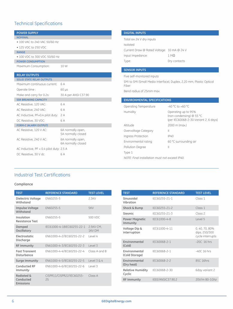
Technical Specifications
POWER SUPPLYNOMINAL
• 100 VAC to 240 VAC 50/60 Hz
• 125 VDC to 250 VDC RANGE
• 100 VDC to 300 VDC 50/60 Hz POWER CONSUMPTION
Maximum Consumption: 10 W
RELAY OUTPUTSSOLID STATE RELAY OUTPUTS
Maximum continuous current: 6 A
Operate time : 60 μs
Make and carry for 0.2s: 30 A per ANSI C37.90SSR BREAKING CAPACITY
AC Resistive, 120 VAC: 6 A
AC Resistive, 240 VAC: 6 A
AC Inductive, PF=0.4 pilot duty: 2 A
DC Resistive, 30 VDC: 6 AFORM-C (ALARM OUTPUT)
AC Resistive, 120 V AC: 6A normally open, 5A normally closed
AC Resistive, 240 V AC: 6A normally open, 6A normally closed
AC Inductive, PF = 0.4 pilot duty: 2.5 A
DC Resistive, 30 V dc 6 A
DIGITAL INPUTS
Total six 24 V dry inputs
Isolated
Current Draw @ Rated Voltage: 10 mA @ 24 V
Input Impedance: 1 MΩ
Type: Dry contacts
SENSOR INPUTS
Five self-monitored inputs
SMI to SMI (Small Media Interface), Duplex, 2.20 mm, Plastic Optical Fiber
Bend radius of 25mm max
ENVIRONMENTAL SPECIFICATIONS
Operating Temperature -40 °C to +60 °C
Humidity Operating up to 95% (non condensing) @ 55 °C (per IEC60068-2-30 Variant 2, 6 days)
Altitude 2000 m (max.)
Overvoltage Category II
Ingress Protection IP40
Environmental rating 60 °C surrounding air
Pollution Degree II
Type 1
NOTE: Final installation must not exceed IP40.
Industrial Test Certifications
Compliance
TEST REFERENCE STANDARD TEST LEVEL
Dielectric Voltage Withstand
EN60255-5 2.3KV
Impulse Voltage Withstand
EN60255-5 5KV
Insulation Resistance Test
EN60255-5 500 VDC
Damped Oscillatory
IEC61000-4-18IEC60255-22-1 2.5KV CM, 1KV DM
Electrostatic Discharge
EN61000-4-2/IEC60255-22-2 Level 4
RF Immunity EN61000-4-3/IEC60255-22-3 Level 3
Fast Transient Disturbance
EN61000-4-4/IEC60255-22-4 Class A and B
Surge Immunity EN61000-4-5/IEC60255-22-5 Level 3 & 4
Conducted RF Immunity
EN61000-4-6/IEC60255-22-6 Level 3
Radiated & Conducted Emissions
CISPR11/CISPR22/IEC60255-25
Class A
TEST REFERENCE STANDARD TEST LEVEL
Sinusoidal Vibration
IEC60255-21-1 Class 1
Shock & Bump IEC60255-21-2 Class 1
Siesmic IEC60255-21-3 Class 2
Power Magnetic Immunity
IEC61000-4-8 Level 5
Voltage Dip & interruption
IEC61000-4-11 0, 40, 70, 80% dips, 250/300 cycle interrupts
Environmental (Cold)
IEC60068-2-1 -20C 16 hrs
Environmental (Cold Storage)
IEC60068-2-1 -40C 16 hrs
Environmental (Dry heat)
IEC60068-2-2 85C 16hrs
Relative Humidity Cyclic
IEC60068-2-30 6day variant 2
RF Immunity IEEE/ANSIC37.90.2 20V/m 80-1Ghz
7GEDigitalEnergy.com
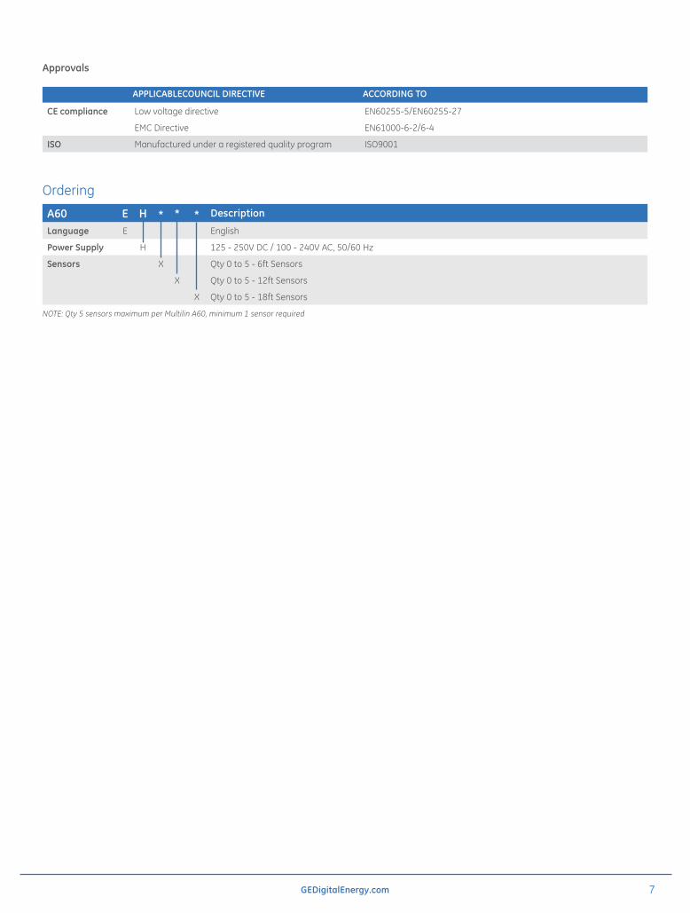
Approvals
APPLICABLECOUNCIL DIRECTIVE ACCORDING TO
CE compliance Low voltage directive EN60255-5/EN60255-27
EMC Directive EN61000-6-2/6-4
ISO Manufactured under a registered quality program ISO9001
Ordering
A60 E H * * * Description
Language E English
Power Supply H 125 - 250V DC / 100 - 240V AC, 50/60 Hz
Sensors X Qty 0 to 5 - 6ft Sensors
X Qty 0 to 5 - 12ft Sensors
X Qty 0 to 5 - 18ft Sensors
NOTE: Qty 5 sensors maximum per Multilin A60, minimum 1 sensor required

g imagination at work
GEA-12706B(E)English131127
Digital Energy 650 Markland St. Markham, ON Canada L6C 0M1 Toll Free (NA Only): 1-800-547-8629 Tel: 905-927-7070 Fax: 905-927-5098 [email protected]
GEDigitalEnergy.comCopyright 2012, General Electric Company. All Rights Reserved.
GE reserves the right to make changes to specifications of products described at any time without notice and without obligation to notify any person of such changes.
GE, the GE monogram, Multilin and A60 are trademarks of General Electric Company.