Embed Size (px)
Citation preview

Univerzita Pavla Jozefa Šafárika v Košiciach
Prírodovedecká fakulta
Ústav Informatiky
ADVANCED LIGHTING IN 2D
GRAPHICS
ŠTUDENTSKÁ VEDECKÁ KONFERENCIA
Košice 2013
Ferdinand Majerech, 3Ib

Abstract:
We aim to describe a lighting model usable in 2D graphics based on methods usuallyused in 3D, providing a low-cost alternative way to create realistic visuals in real time.The result of our work is a general-purpose pre-renderer generating data needed by thislighting model as well as an efficient reference implementation of the model.
Keywords: Real-time computer graphics, 2D graphics, lighting, game development, sprite,
normal map, pre-rendering, shader
Introduction
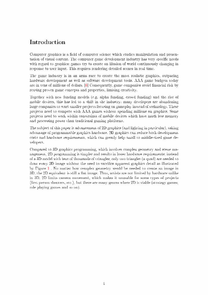
Computer graphics is a field of computer science which studies manipulation and presen-tation of visual content. The computer game development industry has very specific needswith regard to graphics; games try to create an illusion of world continuously changing inresponse to user input. This requires rendering detailed scenes in real time.
The game industry is in an arms race to create the most realistic graphics, outpacinghardware development as well as software development tools. AAA game budgets todayare in tens of millions of dollars. [6] Consequently, game companies avoid financial risk byreusing proven game concepts and properties, limiting creativity.
Together with new funding models (e.g. alpha funding, crowd funding) and the rise ofmobile devices, this has led to a shift in the industry; many developers are abandoninglarge companies to start smaller projects focusing on gameplay instead of technology. Theseprojects need to compete with AAA games without spending millions on graphics. Someprojects need to work within constraints of mobile devices which have much less memoryand processing power than traditional gaming platforms.
The subject of this paper is advancement of 2D graphics (and lighting in particular), takingadvantage of programmable graphics hardware. 2D graphics can reduce both developmentcosts and hardware requirements, which can greatly help small to middle-sized game de-velopers.
Compared to 3D graphics programming, which involves complex geometry and scene ma-nagement, 2D programming is simpler and results in lower hardware requirements; insteadof a 3D model with tens of thousands of triangles, only two triangles (a quad) are needed todraw every 2D image without the need to sacrifice apparent graphics detail as illustratedby Figure 1 . No matter how complex geometry would be needed to create an image in3D, the 2D equivalent is still a flat image. Thus, artists are not limited by hardware unlikein 3D. 2D limits camera movement, which makes it unusable for some types of projects(first person shooters, etc.), but there are many genres where 2D is viable (strategy games,role-playing games and so on).
1
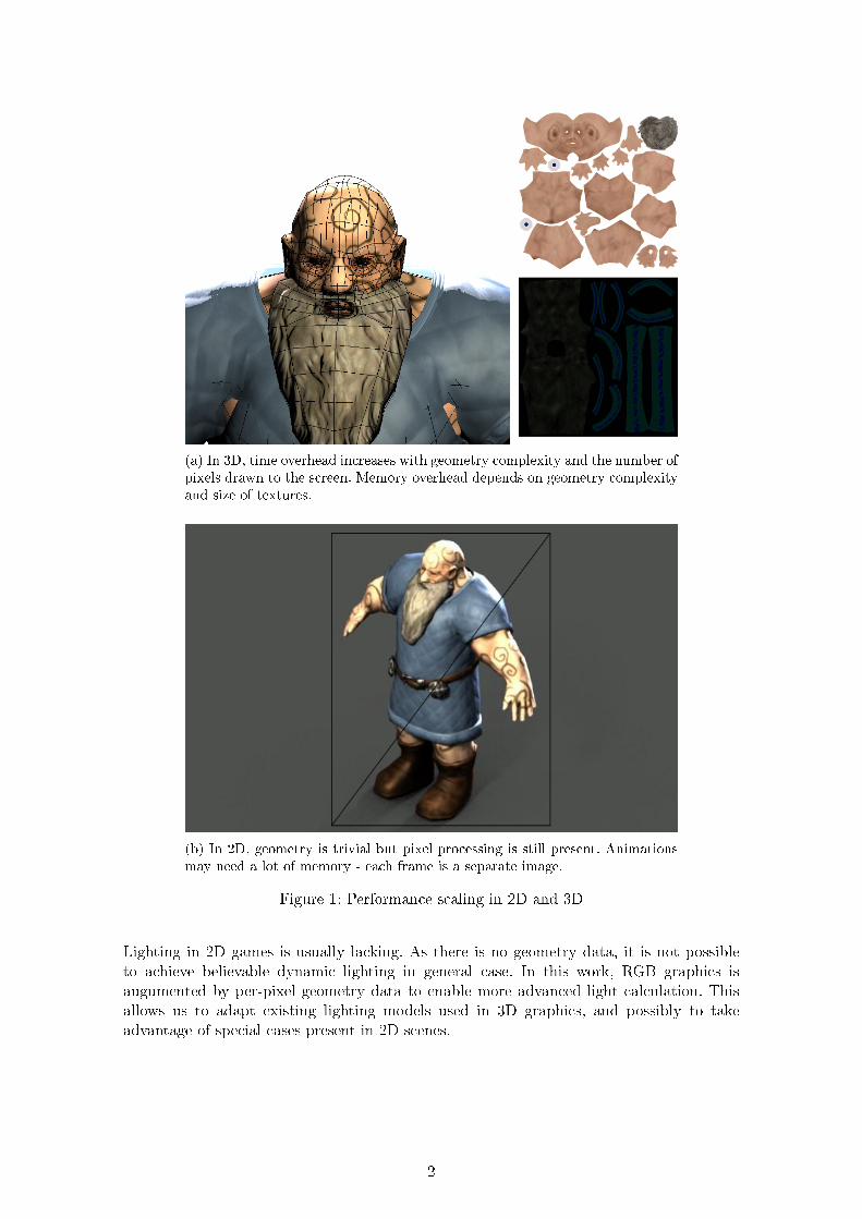
(a) In 3D, time overhead increases with geometry complexity and the number ofpixels drawn to the screen. Memory overhead depends on geometry complexityand size of textures.
(b) In 2D, geometry is trivial but pixel processing is still present. Animationsmay need a lot of memory - each frame is a separate image.
Figure 1: Performance scaling in 2D and 3D
Lighting in 2D games is usually lacking. As there is no geometry data, it is not possibleto achieve believable dynamic lighting in general case. In this work, RGB graphics isaugumented by per-pixel geometry data to enable more advanced light calculation. Thisallows us to adapt existing lighting models used in 3D graphics, and possibly to takeadvantage of special cases present in 2D scenes.
2
The main goals of this paper are as follows:
∘ Describe an approach to achieve believable dynamic lighting in 2D graphics.
∘ Implement a tool generating auxiliary data for 2D lighting from 3D data (a pre-renderer).
∘ Implement a demonstration program of a dynamic lighting model working on 2Ddata.
An important secondary goal is to make results of our work accessible. All source code isreleased under the Boost open source license, and the pre-renderer can be used by various2D graphics projects.
Terminology
This section describes some graphics terms used in this article. Shaders (programmableGPU functionality) are described in more detail in a separate section.
∘ GPU: Graphics Processing Unit. Hardware dedicated to graphics calculation.
∘ OpenGL: Graphics programming API supported by most gaming platforms.
∘ Direct3D: Graphics programming API used on Windows, Windows Phone and theXbox consoles.
∘ Sprite: An image or an animation representing an object in a 2D game. Often hasmultiple facings, separate images representing the object rotated with various angles.
∘ Pre-renderer: A tool that creates 2D sprites from a 3D model.
∘ Vertex: A point in space forming geometry, usually including more data than justa position (e.g. a texture coordinate, color or normal).
∘ Primitive: A basic graphics object, such as a triangle, line or a point. Usually madeof multiple vertices.
∘ Fragment: A basic element of 2D processing on a GPU. Often this is the same as apixel there might be more than one fragment per pixel e.g. if multisample antialiasingis used.
Shaders
In the past, graphics features such as coordinate transformations, lighting and fog wereimplemented directly on GPU hardware, and the programmer could not extend or modifythem. This is referred to as fixed-function pipeline, and can be used through the olderversions of the OpenGL and Direct3D APIs.
During the 2000s, GPUs moved to more programmable designs. Most graphics features areno longer provided by the GPU and must be implemented by the programmer in languagesdesigned specifically to run on GPU. The most common of these are the OpenGL Shading
Language (GLSL) used by the OpenGL and OpenGL ES APIs and High Level Shader
Language (HLSL) used by Direct3D. Today, fixed-function GPUs are a rarity, the lastmajor fixed-function platform being the Nintendo Wii.
3
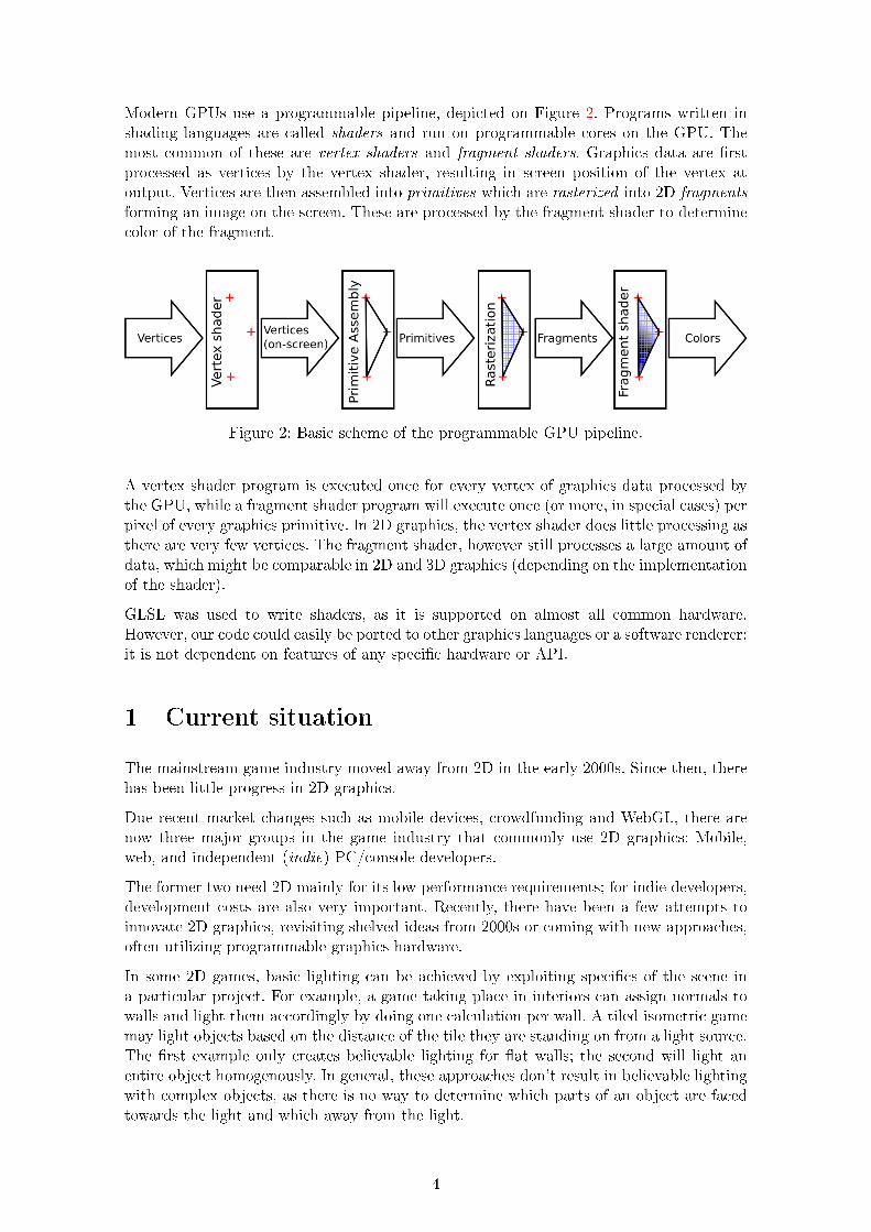
Modern GPUs use a programmable pipeline, depicted on Figure 2. Programs written inshading languages are called shaders and run on programmable cores on the GPU. Themost common of these are vertex shaders and fragment shaders. Graphics data are firstprocessed as vertices by the vertex shader, resulting in screen position of the vertex atoutput. Vertices are then assembled into primitives which are rasterized into 2D fragments
forming an image on the screen. These are processed by the fragment shader to determinecolor of the fragment.
Figure 2: Basic scheme of the programmable GPU pipeline.
A vertex shader program is executed once for every vertex of graphics data processed bythe GPU, while a fragment shader program will execute once (or more, in special cases) perpixel of every graphics primitive. In 2D graphics, the vertex shader does little processing asthere are very few vertices. The fragment shader, however still processes a large amount ofdata, which might be comparable in 2D and 3D graphics (depending on the implementationof the shader).
GLSL was used to write shaders, as it is supported on almost all common hardware.However, our code could easily be ported to other graphics languages or a software renderer;it is not dependent on features of any specific hardware or API.
1 Current situation
The mainstream game industry moved away from 2D in the early 2000s. Since then, therehas been little progress in 2D graphics.
Due recent market changes such as mobile devices, crowdfunding and WebGL, there arenow three major groups in the game industry that commonly use 2D graphics: Mobile,web, and independent (indie) PC/console developers.
The former two need 2D mainly for its low performance requirements; for indie developers,development costs are also very important. Recently, there have been a few attempts toinnovate 2D graphics, revisiting shelved ideas from 2000s or coming with new approaches,often utilizing programmable graphics hardware.
In some 2D games, basic lighting can be achieved by exploiting specifics of the scene ina particular project. For example, a game taking place in interiors can assign normals towalls and light them accordingly by doing one calculation per wall. A tiled isometric gamemay light objects based on the distance of the tile they are standing on from a light source.The first example only creates believable lighting for flat walls; the second will light anentire object homogenously. In general, these approaches don’t result in believable lightingwith complex objects, as there is no way to determine which parts of an object are facedtowards the light and which away from the light.
4
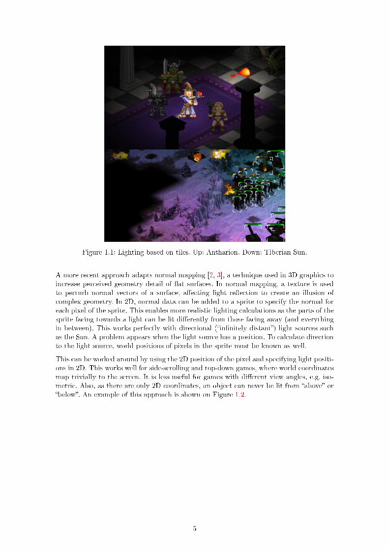
Figure 1.1: Lighting based on tiles. Up: Antharion. Down: Tiberian Sun.
A more recent approach adapts normal mapping [2, 3], a technique used in 3D graphics toincrease perceived geometry detail of flat surfaces. In normal mapping, a texture is usedto perturb normal vectors of a surface, affecting light reflection to create an illusion ofcomplex geometry. In 2D, normal data can be added to a sprite to specify the normal foreach pixel of the sprite. This enables more realistic lighting calculations as the parts of thesprite facing towards a light can be lit differently from those facing away (and everythingin between). This works perfectly with directional (“infinitely distant”) light sources suchas the Sun. A problem appears when the light source has a position. To calculate directionto the light source, world positions of pixels in the sprite must be known as well.
This can be worked around by using the 2D position of the pixel and specifying light positi-ons in 2D. This works well for side-scrolling and top-down games, where world coordinatesmap trivially to the screen. It is less useful for games with different view angles, e.g. iso-metric. Also, as there are only 2D coordinates, an object can never be lit from “above” or“below”. An example of this approach is shown on Figure 1.2.
5
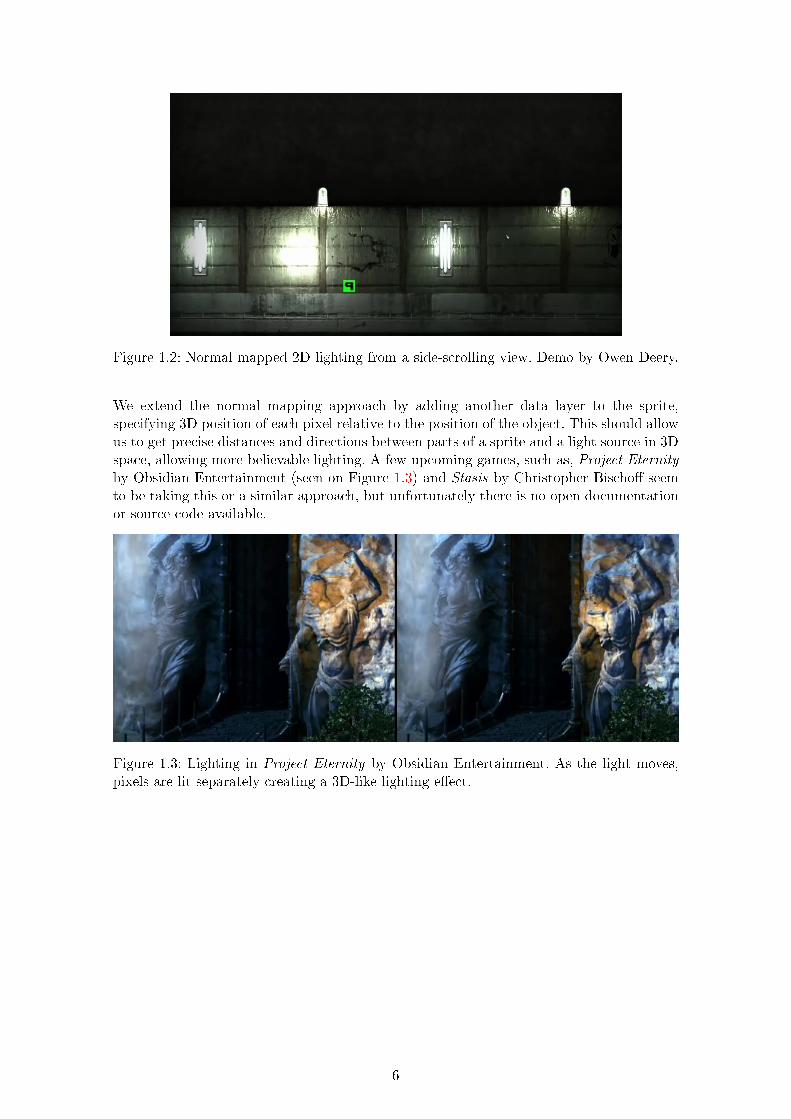
Figure 1.2: Normal mapped 2D lighting from a side-scrolling view. Demo by Owen Deery.
We extend the normal mapping approach by adding another data layer to the sprite,specifying 3D position of each pixel relative to the position of the object. This should allowus to get precise distances and directions between parts of a sprite and a light source in 3Dspace, allowing more believable lighting. A few upcoming games, such as, Project Eternityby Obsidian Entertainment (seen on Figure 1.3) and Stasis by Christopher Bischoff seemto be taking this or a similar approach, but unfortunately there is no open documentationor source code available.
Figure 1.3: Lighting in Project Eternity by Obsidian Entertainment. As the light moves,pixels are lit separately creating a 3D-like lighting effect.
6
2 Our approach
Our work can be separated into three main parts:
∘ Acquire 2D data (sprites) enhanced with auxiliary data (normals, positions) neededfor lighting. This is a part of graphics asset authoring.
∘ Load sprites, associate them with data specific with the current scene (such as lightsources, object position) and pass them to the GPU as textures. This is done atruntime by the CPU code of the application.
∘ Calculate lighting on the GPU using the sprite and scene data. This is done atruntime by shader code running on the GPU.
Sprite creation
There are various ways to create 2D sprites. Besides color data, our lighting model alsoneeds the normal and position of each pixel. Sprite creation should also be as easy aspossible; after all, this is one of the main reasons to use 2D. Some ways to create spritesare listed below:
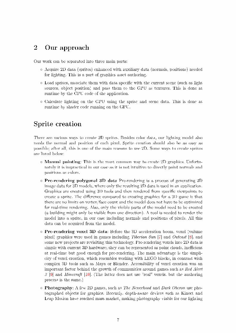
∘ Manual painting: This is the most common way to create 2D graphics. Unfortu-nately it is impractical in our case as it is not intuitive to directly paint normals andpositions as colors.
∘ Pre-rendering polygonal 3D data Pre-rendering is a process of generating 2Dimage data for 3D models, where only the resulting 2D data is used in an application.Graphics are created using 3D tools and then rendered from specific viewpoints tocreate a sprite. The difference compared to creating graphics for a 3D game is thatthere are no limits on vertex/face count and the model does not have to be optimizedfor real-time rendering. Also, only the visible parts of the model need to be created(a building might only be visible from one direction). A tool is needed to render themodel into a sprite, in our case including normals and positions of pixels. All thisdata can be acquired from the model.
∘ Pre-rendering voxel 3D data: Before the 3D acceleration boom, voxel (volumepixel) graphics were used in games including Tiberian Sun [7] and Outcast [8], andsome new projects are revisiting this technology. Pre-rendering voxels into 2D data issimple with current 3D hardware; they can be represented as point clouds, inefficientat real-time but good enough for pre-rendering. The main advantage is the simpli-city of voxel creation, which resembles working with LEGO blocks, in contrast withcomplex 3D tools such as Maya or Blender. Accessibility of voxel creation was animportant factor behind the growth of communities around games such as Red Alert
2 [9] and Minecraft [10]. (The latter does not use “real” voxels, but the authoringprocess is the same.)
∘ Photography: A few 2D games, such as The Neverhood and Dark Oberon use pho-tographed objects for graphics. Recently, depth-aware devices such as Kinect andLeap Motion have reached mass market, making photography viable for our lighting
7
model. Unfortunately, currently available devices have very low resolutions. However,this is likely to improve in future with the next generation of depth-aware devices.
Figure 2.1: From left to right: Painted, pre-rendered from polygonal 3D data, pre-renderedfrom voxel 3D data, photography.
As the sprite creation step is separate from run time, any of these approaches can be usedas long as it creates a sprite in compatible format.
We chose to use pre-rendered polygonal data, as it is the most compatible way of workingwith existing developer pipelines. However, it might be interesting to explore voxels infuture as they provide a very low barrier of entry for artists, and photography mightbecome more viable as technology improves.
Pre-renderer
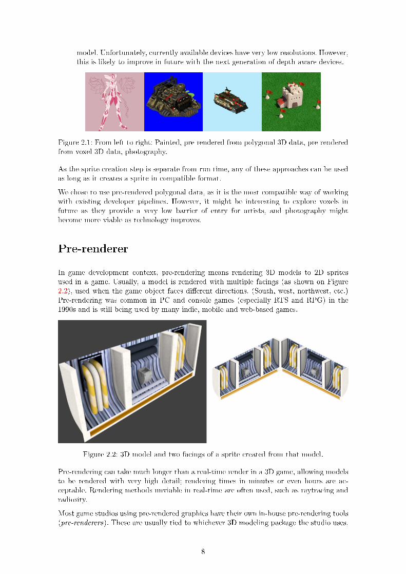
In game development context, pre-rendering means rendering 3D models to 2D spritesused in a game. Usually, a model is rendered with multiple facings (as shown on Figure2.2), used when the game object faces different directions. (South, west, northwest, etc.)Pre-rendering was common in PC and console games (especially RTS and RPG) in the1990s and is still being used by many indie, mobile and web-based games.
Figure 2.2: 3D model and two facings of a sprite created from that model.
Pre-rendering can take much longer than a real-time render in a 3D game, allowing modelsto be rendered with very high detail; rendering times in minutes or even hours are ac-ceptable. Rendering methods unviable in real-time are often used, such as raytracing andradiosity.
Most game studios using pre-rendered graphics have their own in-house pre-rendering tools(pre-renderers). These are usually tied to whichever 3D modeling package the studio uses,
8
and a new tool is often written for every game. Most pre-renderers are not freely available[15] and those that are [14] don’t suit our needs. (In particular, source code access is neededto implement support to to render normals and positions for our lighting model).
We have decided to implement a custom pre-renderer for our lighting model, with thefollowing goals:
∘ Support for multiple 3D formats, to support any modeling tool.
∘ Configurable for varying view angles. (Top-down, isometric, etc.)
∘ Support for any number of object facings. (8 are most common, some games use 16)
∘ Can output colors, normals and positions.
∘ Command-line interface to allow scripting.
∘ Open source and gratis.
Projection
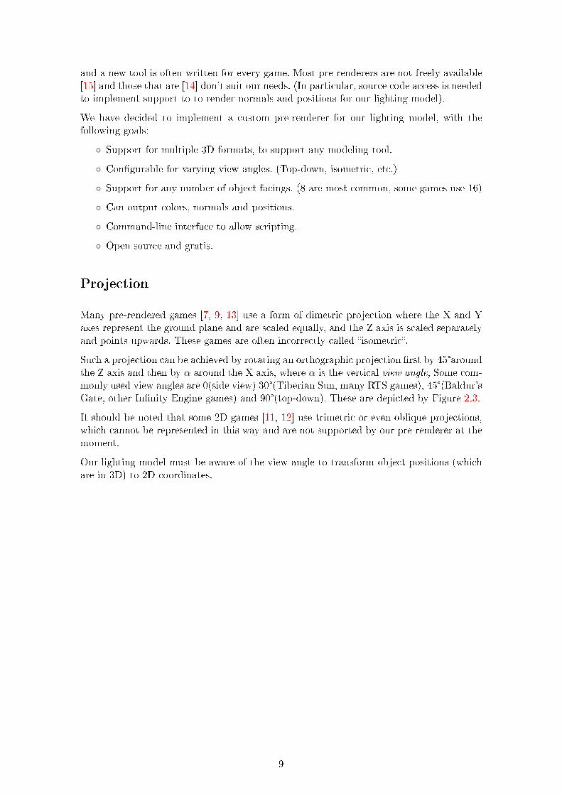
Many pre-rendered games [7, 9, 13] use a form of dimetric projection where the X and Yaxes represent the ground plane and are scaled equally, and the Z axis is scaled separatelyand points upwards. These games are often incorrectly called “isometric”.
Such a projection can be achieved by rotating an orthographic projection first by 45°aroundthe Z axis and then by 𝛼 around the X axis, where 𝛼 is the vertical view angle, Some com-monly used view angles are 0(side view) 30°(Tiberian Sun, many RTS games), 45°(Baldur’sGate, other Infinity Engine games) and 90°(top-down). These are depicted by Figure 2.3.
It should be noted that some 2D games [11, 12] use trimetric or even oblique projections,which cannot be represented in this way and are not supported by our pre-renderer at themoment.
Our lighting model must be aware of the view angle to transform object positions (whichare in 3D) to 2D coordinates.
9
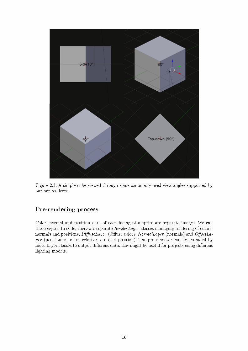
Figure 2.3: A simple cube viewed through some commonly used view angles supported byour pre-renderer.
Pre-rendering process
Color, normal and position data of each facing of a sprite are separate images. We callthese layers. In code, there are separate RenderLayer classes managing rendering of colors,normals and positions; DiffuseLayer (diffuse color), NormalLayer (normals) and OffsetLa-
yer (position, as offset relative to object position). The pre-renderer can be extended bymore Layer classes to output different data; this might be useful for projects using differentlighting models.
10
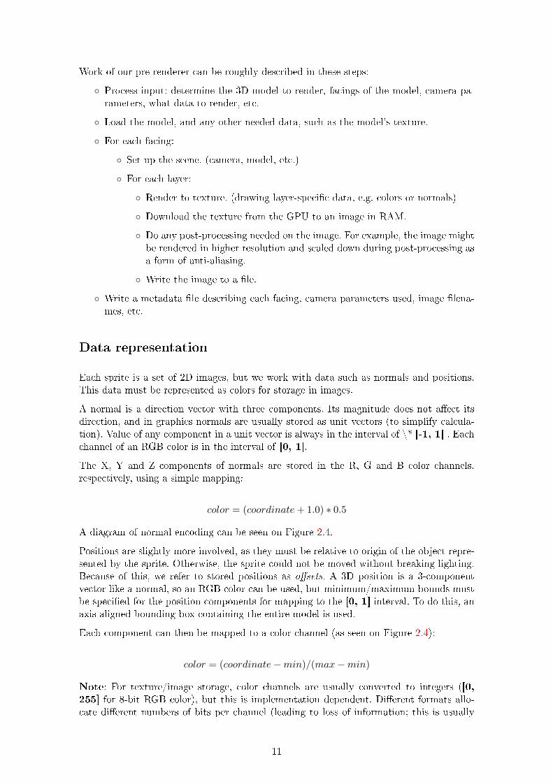
Work of our pre-renderer can be roughly described in these steps:
∘ Process input: determine the 3D model to render, facings of the model, camera pa-rameters, what data to render, etc.
∘ Load the model, and any other needed data, such as the model’s texture.
∘ For each facing:
∘ Set up the scene. (camera, model, etc.)
∘ For each layer:
∘ Render to texture. (drawing layer-specific data, e.g. colors or normals)
∘ Download the texture from the GPU to an image in RAM.
∘ Do any post-processing needed on the image. For example, the image mightbe rendered in higher resolution and scaled down during post-processing asa form of anti-aliasing.
∘ Write the image to a file.
∘ Write a metadata file describing each facing, camera parameters used, image filena-mes, etc.
Data representation
Each sprite is a set of 2D images, but we work with data such as normals and positions.This data must be represented as colors for storage in images.
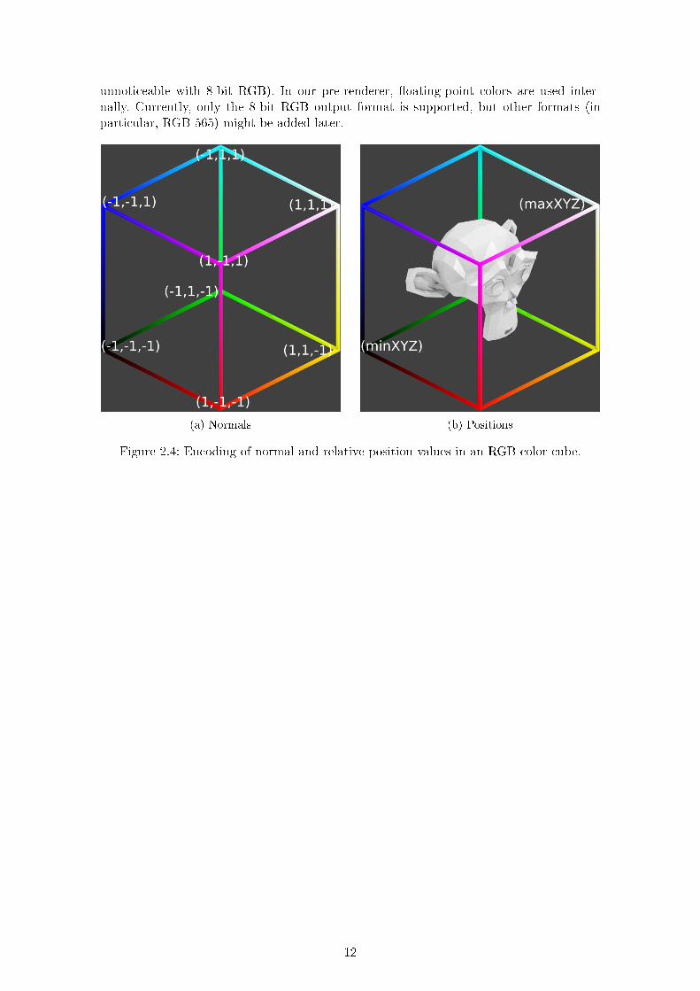
A normal is a direction vector with three components. Its magnitude does not affect itsdirection, and in graphics normals are usually stored as unit vectors (to simplify calcula-tion). Value of any component in a unit vector is always in the interval of \* [-1, 1] . Eachchannel of an RGB color is in the interval of [0, 1].
The X, Y and Z components of normals are stored in the R, G and B color channels,respectively, using a simple mapping:
𝑐𝑜𝑙𝑜𝑟 = (𝑐𝑜𝑜𝑟𝑑𝑖𝑛𝑎𝑡𝑒+ 1.0) * 0.5
A diagram of normal encoding can be seen on Figure 2.4.
Positions are slightly more involved, as they must be relative to origin of the object repre-sented by the sprite. Otherwise, the sprite could not be moved without breaking lighting.Because of this, we refer to stored positions as offsets. A 3D position is a 3-componentvector like a normal, so an RGB color can be used, but minimum/maximum bounds mustbe specified for the position components for mapping to the [0, 1] interval. To do this, anaxis-aligned bounding box containing the entire model is used.
Each component can then be mapped to a color channel (as seen on Figure 2.4):
𝑐𝑜𝑙𝑜𝑟 = (𝑐𝑜𝑜𝑟𝑑𝑖𝑛𝑎𝑡𝑒−𝑚𝑖𝑛)/(𝑚𝑎𝑥−𝑚𝑖𝑛)
Note: For texture/image storage, color channels are usually converted to integers ([0,255] for 8-bit RGB color), but this is implementation dependent. Different formats allo-cate different numbers of bits per channel (leading to loss of information; this is usually
11
unnoticeable with 8-bit RGB). In our pre-renderer, floating-point colors are used inter-nally. Currently, only the 8-bit RGB output format is supported, but other formats (inparticular, RGB-565) might be added later.
(a) Normals (b) Positions
Figure 2.4: Encoding of normal and relative position values in an RGB color cube.
12
Graphics scene
Once we have sprites with all needed data we need to send them to the GPU when drawingthe graphics scene. There are also other scene elements, such as light sources and thecamera.
While our graphics scene is 2D, positions of objects and light sources must be in 3D forour lighting model to work. These 3D coordinates must be available to the shader wherethe lighting model is computed. Positioning of the sprites on the screen is determined bythe vertex shader.
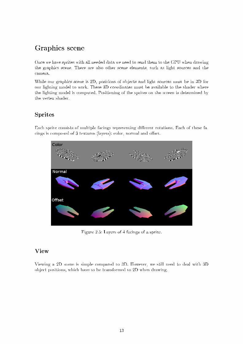
Sprites
Each sprite consists of multiple facings representing different rotations. Each of these fa-cings is composed of 3 textures (layers): color, normal and offset.
Figure 2.5: Layers of 4 facings of a sprite.
View
Viewing a 2D scene is simple compared to 3D. However, we still need to deal with 3Dobject positions, which have to be transformed to 2D when drawing.
13
The following parameters affect the view:
∘ View center A 2D vector specifying the center of the viewport.
∘ Zoom Allows to zoom the view in/out, scaling the graphics. This is not an essentialparameter, but it is useful for some types of games.
∘ View angle View angle of the projection used when pre-rendering.
The first two are used to create an orthographic projection matrix that projects 2D datato the screen. The view angle is used to recreate the projection used for pre-rendering onshader, to project the 3D object position to 2D.
Light sources
Our lighting model works with two light source types: point lights and directional lights.Point lights have a 3D position and can be used to model light sources such as a lampor a fire. Directional lights are “infinitely distant”; they only have a direction towards thelight. They can be used to model distant light sources such as the Sun, or a distant nuclearexplosion.
A scene in a game can have a large number of light sources; for instance, in a strategygame, every unit might have its own light, resulting in hundreds or thousands of lights.Calculating the contribution of each light source to every pixel would quickly become tooresource-intensive. Implementation also poses a limitation; GLSL (as of OpenGL 2.0) doesnot support dynamic arrays which forces us to use a fixed maximum number of lights. Evenif dynamic arrays were supported, lighting calculation with too many light sources mightquickly become too resource-intensive. Because of this, our scene currently is hardcoded towork with at most 6 point and 2 directional lights.
In future work we plan to work around this limitation by managing many virtual lights(using a spatial management data structure such as an octree) and mapping the closestor most influential light sources to shader lights based on the object being drawn at themoment.
Drawing
Each game object is associated with a sprite used as its graphical representation. Whendrawing an object, the facing of the sprite representing the object’s rotation is chosen, andthe color, normal and offset textures of that facing are used with separate texture units.
View parameters, light sources, object position and the bounding box are uploaded to theGPU as uniform variables or uniforms (shader program constants).
Finally, the sprite is rendered as a pair of textured triangles. Lighting is calculated byshaders on every pixel.
Lighting
Our lighting calculation runs entirely on fragment shader, once per pixel. Using the pre-rendered data in the sprite and object position, pixel world space position and normal is
14

reconstructed. This allows lighting calculation in 3D.
Lighting model
Blinn-Phong [1] reflection model, which is probably the most common lighting model inreal-time 3D graphics and is also implemented on fixed-function pipelines of OpenGL andDirect3D.
Currently, specular lighting is not calculated for performance reasons (to allow supportof old low-end hardware), although it could be added in future for newer/more powerfulGPUs. This means that at the moment shiny surfaces such as metals cannot be modeled.Also, it should be noted that the Blinn-Phong model only differs from the older Phong’s[5] reflection model in specular lighting, so our lighting model is in fact based on a subsetof both these models.
The Blinn-Phong model provides quite realistic results without expensive computation. Itsmain advantage, however, is that it is very commonly used in real-time 3D graphics, andmany extensions have been developed on top of it. This should allow us to improve themodel further in future without reinventing the wheel.
Our current light calculation (done separately for each color channel of the RGB color) isas follows:
𝑖𝑙𝑙𝑢𝑚𝑖𝑛𝑡𝑎𝑡𝑖𝑜𝑛 = 𝑖𝑎 *𝑚𝑑 +𝑙𝑖𝑔ℎ𝑡𝐶𝑜𝑢𝑛𝑡∑︁
𝑙=1
(𝑎𝑙 *𝑚𝑑 * 𝑖𝑑,𝑙 * 𝑑𝑖𝑟𝑒𝑐𝑡𝑖𝑜𝑛𝑇𝑜𝐿𝑖𝑔ℎ𝑡𝑙 * 𝑛𝑜𝑟𝑚𝑎𝑙)
𝑚𝑑 is diffuse material color. 𝑖𝑎 is the global ambient light color, 𝑖𝑑,𝑙 is diffuse color of thelight, and 𝑎𝑙 is the attenuation factor, which decreases light intensity with distance from athe source. For directional lights, the attenuation factor is 1. For point lights, it decreaseswith distance from the light source:
𝑎𝑙 = 1/(1 + 𝑎𝑡𝑡𝑒𝑛𝑢𝑎𝑡𝑖𝑜𝑛𝑙 * 𝑑𝑖𝑠𝑡𝑎𝑛𝑐𝑒𝑇𝑜𝐿𝑖𝑔ℎ𝑡𝑙)
The 𝑎𝑡𝑡𝑒𝑛𝑢𝑎𝑡𝑖𝑜𝑛 parameter of a light can be used to tweak the area affected by the light.To better match reality, 𝑑𝑖𝑠𝑡𝑎𝑛𝑐𝑒𝑇𝑜𝐿𝑖𝑔ℎ𝑡𝑙 should be squared. However, because colors arelimited to the interval of [0,1], avoiding the squaring results in more believable lighting.This could be improved by implementing HDR (High Dynamic Range) lighting in future(using the full range of floating-point values).
Unlike the Blinn-Phong model there is no separate ambient material color. The diffusecolor is reused as it avoids the need for even more data per pixel, and cases where ambientcolor differs from diffuse color are rare.
15

3 Initial demo implementation
The first version of the lighting implementation was focused on getting the correct functi-onality to work as fast as possible, without optimization. This would allow us to measureperformance early and to determine how to best improve it.
The demo was written in the D programming language [16], using the Derelict [17] libraryto access OpenGL and SDL [18] for cross-platform input handling and windowing. Thegl3n [19] library was used for GLSL-like vectors and matrices. OpenGL 2.0 was used forgraphics; this version is supported by old GPUs we want to support, and is almost identicalto OpenGL ES 2.0 used on mobile devices.
This is a very high-level scheme of CPU processing done to draw a single frame in thedemo:
∘ Set up frame, bind the shader program
∘ For each visible object:
∘ Upload current view state uniforms to the GPU.
∘ Upload light source uniforms to the GPU.
∘ Upload world-space object 3D position and bounding box uniforms to the GPU.
∘ Bind vertex and index buffers for the sprite of the object.
∘ Bind color, normal and offset textures for the sprite of the object.
∘ Draw the sprite (asynchronously on the GPU).
∘ Release the shader program, finish frame.
The following work is done on the vertex shader for each sprite:
∘ For each vertex (of 6 - two triangles):
∘ Calculate the view matrix from view parameters.
∘ Determine sprite position on screen using view matrix.
∘ Determine final vertex position.
The pixel shader works as follows:
∘ For each pixel of the sprite:
∘ Decode (world-space) normal.
∘ Compute 3D pixel position from object position, bounding box and pixel offset.
∘ Compute ambient lighting contribution.
∘ For each directional light (of 4):
∘ Compute diffuse lighting contribution.
∘ For each point light (of 8):
∘ Compute diffuse lighting contribution.
16
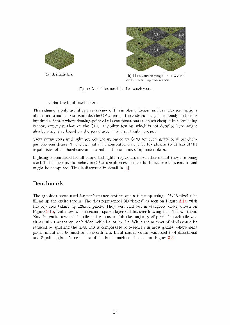
(a) A single tile. (b) Tiles were arranged in staggeredorder to fill up the screen.
Figure 3.1: Tiles used in the benchmark
∘ Set the final pixel color.
This scheme is only useful as an overview of the implementation; not to make assumptionsabout performance. For example, the GPU part of the code runs asynchronously on tens orhundreds of cores where floating-point SIMD computations are much cheaper but branchingis more expensive than on the CPU. Visibility testing, which is not detailed here, mightalso be expensive based on the scene used in any particular project.
View parameters and light sources are uploaded to GPU for each sprite to allow chan-ges between draws. The view matrix is computed on the vertex shader to utilize SIMDcapabilities of the hardware and to reduce the amount of uploaded data.
Lighting is computed for all supported lights, regardless of whether or not they are beingused. This is because branches on GPUs are often expensive; both branches of a conditionalmight be computed. This is discussed in detail in [4].
Benchmark
The graphics scene used for performance testing was a tile map using 128x96 pixel tilesfilling up the entire screen. The tiles represented 3D “boxes” as seen on Figure 3.1a, withthe top area taking up 128x64 pixels. They were laid out in staggered order shown onFigure 3.1b, and there was a second, sparse layer of tiles overdrawing tiles “below” them.Not the entire area of the tile sprites was useful; the majority of pixels in each tile waseither fully transparent or hidden behind another tile. While the number of pixels could bereduced by splitting the tiles, this is comparable to overdraw in most games, where somepixels might not be used or be overdrawn. Light source count was fixed to 4 directionaland 8 point lights. A screenshot of the benchmark can be seen on Figure 3.2.
17
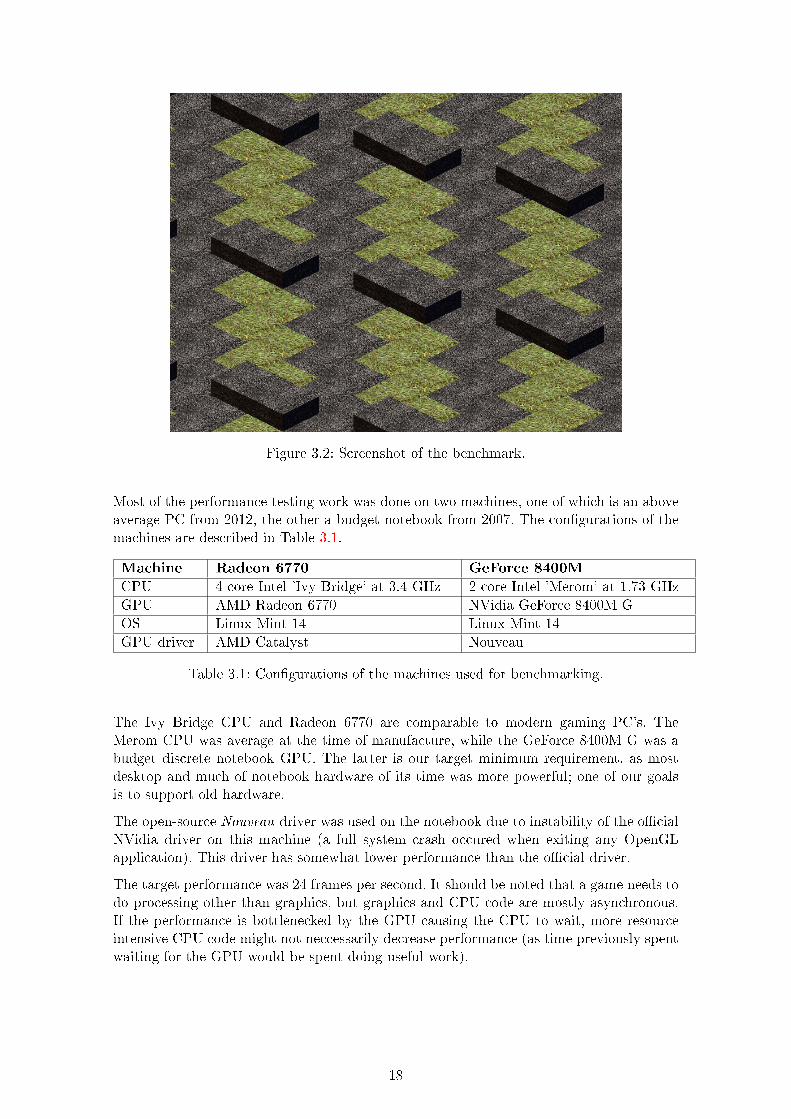
Figure 3.2: Screenshot of the benchmark.
Most of the performance testing work was done on two machines, one of which is an aboveaverage PC from 2012, the other a budget notebook from 2007. The configurations of themachines are described in Table 3.1.
Machine Radeon 6770 GeForce 8400M
CPU 4-core Intel ’Ivy Bridge’ at 3.4 GHz 2-core Intel ’Merom’ at 1.73 GHz
GPU AMD Radeon 6770 NVidia GeForce 8400M G
OS Linux Mint 14 Linux Mint 14
GPU driver AMD Catalyst Nouveau
Table 3.1: Configurations of the machines used for benchmarking.
The Ivy Bridge CPU and Radeon 6770 are comparable to modern gaming PC’s. TheMerom CPU was average at the time of manufacture, while the GeForce 8400M G was abudget discrete notebook GPU. The latter is our target minimum requirement, as mostdesktop and much of notebook hardware of its time was more powerful; one of our goalsis to support old hardware.
The open-source Nouveau driver was used on the notebook due to instability of the officialNVidia driver on this machine (a full system crash occured when exiting any OpenGLapplication). This driver has somewhat lower performance than the official driver.
The target performance was 24 frames per second. It should be noted that a game needs todo processing other than graphics, but graphics and CPU code are mostly asynchronous.If the performance is bottlenecked by the GPU causing the CPU to wait, more resourceintensive CPU code might not neccessarily decrease performance (as time previously spentwaiting for the GPU would be spent doing useful work).
18
Initial performance
Performance results of the initial implementation benchmark can be seen in Table 3.2.
GPU Radeon 6770 GeForce 8400M
Resolution Min. FPS Avg. FPS Min. FPS Avg. FPS
1024x768 175 181 4.5 4.8
1920x1080 84 87 N/A N/A
Table 3.2: Performance before any optimizations
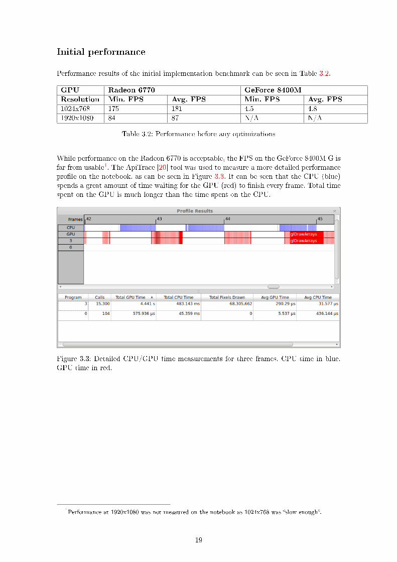
While performance on the Radeon 6770 is acceptable, the FPS on the GeForce 8400M G isfar from usable1. The ApiTrace [20] tool was used to measure a more detailed performanceprofile on the notebook, as can be seen in Figure 3.3. It can be seen that the CPU (blue)spends a great amount of time waiting for the GPU (red) to finish every frame. Total timespent on the GPU is much longer than the time spent on the CPU.
Figure 3.3: Detailed CPU/GPU time measurements for three frames. CPU time in blue,GPU time in red.
1Performance at 1920x1080 was not measured on the notebook as 1024x768 was “slow enough”.
19
4 Improving performance
We have identified a few likely performance issues:
∘ Fragment shader overhead. Geforce 8400M G has low shader processing power com-pared to most GPUs of its generation [21], and most of the overhead of our codeshould be in fragment shader code.
∘ Non-power-of-two textures. Texture sizes depended on sprite sizes, which usually arenot powers of two. Most GPUs don’t guarantee optimal performance with non-power-of-two textures, and some mobile GPUs don’t support them at all.
∘ Too much communication with the GPU:
∘ High draw call count; every sprite was drawn separately. Unfortunately, wecannnot improve this without requiring a higher OpenGL version, as we needdifferent uniform values (at least the object position) for every draw2.
∘ Various GL state change calls were done before every draw, instead of exactlyonce when the state changes. This was a code maintainability measure to avoidGL state from preceding calls to affect new draws. This was a non-essentialfeature.
∘ Uniforms were passed before every draw call, instead of only after a change ofvalues. Only some of the uniforms (e.g. object position) change before everydraw. Most could be passed once per many draws.
∘ Every sprite used separate textures, causing 3 texture binds per draw
∘ Every sprite used separate vertex/index buffers, which had to be bound beforeevery draw.
Optimizations
CPU optimizations
The first optimization attempt was to improve the CPU code by fixing various low-hangingfruit performance issues (such as excessive memory allocation in some parts of the code).We didn’t expect a great performance improvement as we have already determined thatthe main bottleneck was GPU performance.
Uniform upload and GL state changes
After this we optimized uniform passing to only upload uniform values when they change(with a reset at the beginning of a frame), and then removed redundant OpenGL statechanges before draws.
These optimizations were done on top of each other, not separately from the same co-debase. Performance results after successive optimizations can be seen in tables 4.1 and4.2. While there are measurable improvements on the Radeon 6770, performance changes
2Uniform values cannnot be changed in the middle of a draw call.
20
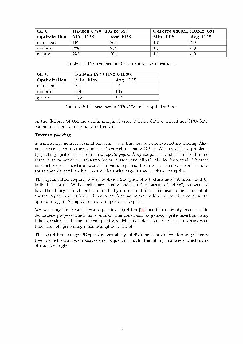
GPU Radeon 6770 (1024x768) GeForce 8400M (1024x768)
Optimization Min. FPS Avg. FPS Min. FPS Avg. FPS
cpu-speed 195 201 4.7 4.9
uniforms 228 234 4.5 4.9
glstate 258 264 4.0 5.0
Table 4.1: Performance in 1024x768 after optimizations.
GPU Radeon 6770 (1920x1080)
Optimization Min. FPS Avg. FPS
cpu-speed 84 92
uniforms 101 105
glstate 105 112
Table 4.2: Performance in 1920x1080 after optimizations.
on the GeForce 8400M are within margin of error. Neither CPU overhead nor CPU-GPUcommunication seems to be a bottleneck.
Texture packing
Storing a large number of small textures wastes time due to excessive texture binding. Also,non-power-of-two textures don’t perform well on many GPUs. We solved these problemsby packing sprite texture data into sprite pages. A sprite page is a structure containingthree large power-of-two textures (color, normal and offset), divided into small 2D areasin which we store texture data of individual sprites. Texture coordinates of vertices of asprite then determine which part of the sprite page is used to draw the sprite.
This optimization requires a way to divide 2D space of a texture into sub-areas used byindividual sprites. While sprites are usually loaded during startup (“loading”), we want tohave the ability to load sprites individually during runtime. This means dimensions of allsprites to pack are not known in advance. Also, as we are working in real-time constraints,optimal usage of 2D space is not as important as speed.
We are using Jim Scott’s texture packing algorithm [22], as it has already been used indemoscene projects which have similar time constraint as games. Sprite insertion usingthis algorithm has linear time complexity, which is not ideal, but in practice inserting eventhousands of sprite images has negligible overhead.
This algorithm manages 2D space by recursively subdividing it into halves, forming a binarytree in which each node manages a rectangle, and its children, if any, manage subrectanglesof that rectangle.
21
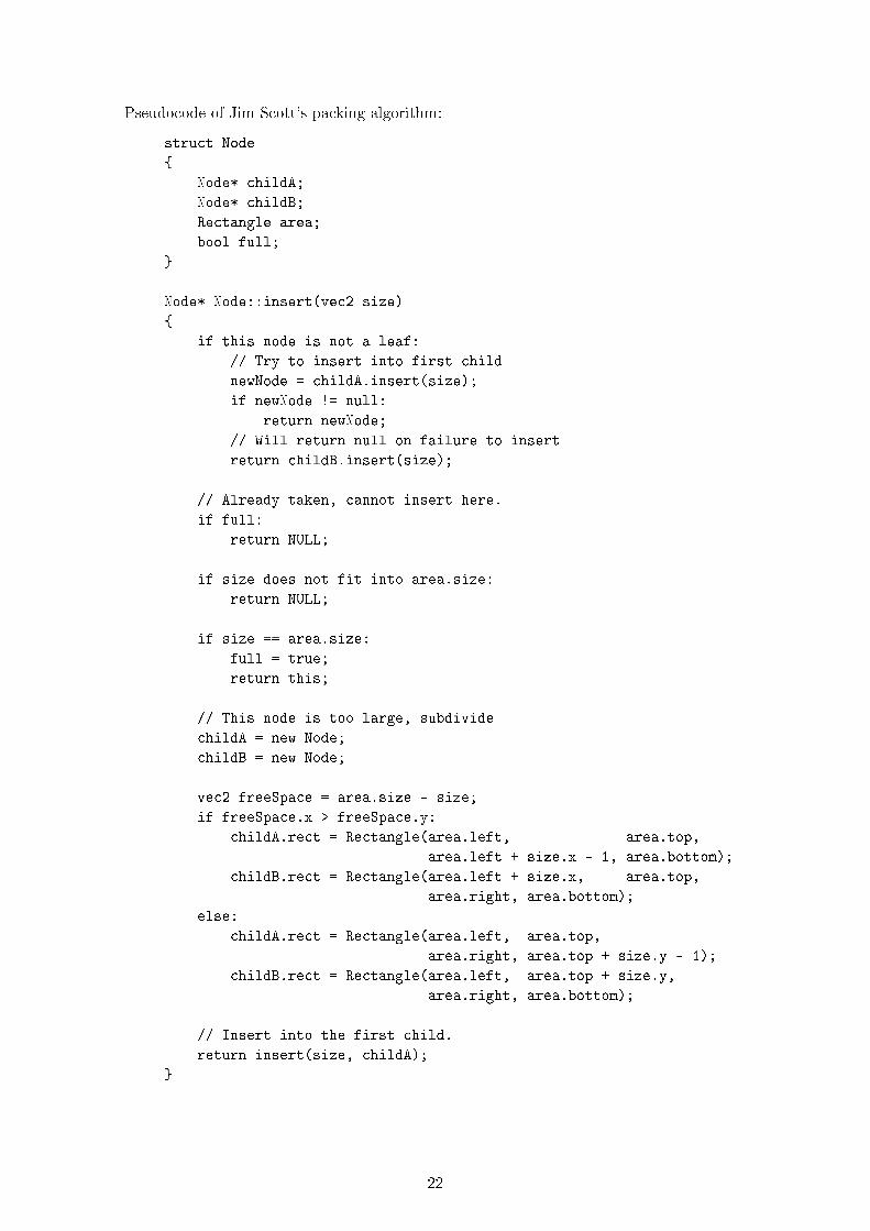
Pseudocode of Jim Scott’s packing algorithm:
struct Node
{
Node* childA;
Node* childB;
Rectangle area;
bool full;
}
Node* Node::insert(vec2 size)
{
if this node is not a leaf:
// Try to insert into first child
newNode = childA.insert(size);
if newNode != null:
return newNode;
// Will return null on failure to insert
return childB.insert(size);
// Already taken, cannot insert here.
if full:
return NULL;
if size does not fit into area.size:
return NULL;
if size == area.size:
full = true;
return this;
// This node is too large, subdivide
childA = new Node;
childB = new Node;
vec2 freeSpace = area.size - size;
if freeSpace.x > freeSpace.y:
childA.rect = Rectangle(area.left, area.top,
area.left + size.x - 1, area.bottom);
childB.rect = Rectangle(area.left + size.x, area.top,
area.right, area.bottom);
else:
childA.rect = Rectangle(area.left, area.top,
area.right, area.top + size.y - 1);
childB.rect = Rectangle(area.left, area.top + size.y,
area.right, area.bottom);
// Insert into the first child.
return insert(size, childA);
}
22

If the current node is not a leaf, we recursively insert into children. If it is a leaf we eitherfail (if the leaf is too small or already taken), succeed if leaf size matches the size beinginserted, or otherwise subdivide the node.
The node is subdivided in either X or Y dimension depending on which dimension hasmore “free space”. Size of the first child in the subdivided dimension will match the size ofthe inserted area.
When a new sprite is inserted into a leaf that does not match the wanted size in X nor Y,we first subdivide one of these dimensions, then try to insert into the first child and thensubdivide the other dimension since free space of the dimension subdivided in parent iszero. This results in a node with exactly the specified size.
Vertex/index packing
Texture packing enabled another optimization; as every sprite worked with a sprite pagestoring its image data, we could also use sprite page to store its vertex data. A singlevertex and index buffer in a sprite page could be used to store vertex and index data forsprites, replacing per-sprite buffers. This allowed us to only rebind vertex/index bufferswhen changing sprite pages, instead of doing so before very draw call. This saved memoryusage and improved performance on the Radeon 6770, but there was no noticeable FPSimprovement on the GeForce 8400M.
Fragment shader branching
Our code avoided branching on the fragment shader, processing all supported lights re-gardless of whether they were enabled or not. We introduced branches into the code to exitearly if fewer light sources were enabled. The branches check if all enabled lights are proces-sed, exitting if true. This has lead to a significant (although still insufficient) performanceincrease on the GeForce 8400M.
Using a loop checking for exit after processing every light source has slightly decreasedperformance, but checking after multiple light sources increased the FPS. The performancegains on this machine were highest when there was one branch per two light sources.
Bounding box in vertices
Bounding boxes used to calculate 3D pixel positions are sprite specific and constant. Thismakes it possible to store them as attributes of vertices used to draw the sprite. Thiswastes some memory (the bounding box has to be specified in 4 vertices). We encode abounding box as 6 floats, and need to specify this for each vertex, resulting in 96 bytes perevery facing of a sprite. Compared to the image data of a sprite facing, which usually takeskilobytes, this is a negligible cost. The advantage of this approach is that we don’t needto upload bounding boxes as uniforms before every draw. This further reduces CPU-GPUcommunication. It is unlikely to improve performance on the GeForce 8400M, as the mainbottleneck there is fragment shader performance.
23

Culling overdrawn pixels
The next optimization uses details of the scene used in our demo to avoid unnecessaryoverdraw. It is usable in most tile-based games, but not in all 2D games. Similar optimi-zations could be used by different projects, however.
Our scene is a map made of tiles, each of which represents a box of space. If there aretiles in front of the tile we are currently drawing, the only part of the visible tile is thetop; we don’t need to draw its sides. This could be exploited by changing the geometry toonly draw the part of the sprite that represents the top. In our case, this part might notalways have the same shape, which would complicate implementation. Also, sprite vertexdata would have to be doubled or modified on runtime, possibly increasing performancecosts.
We solved this by adding a clipping box uniform to the shader, passed before drawing.This is a 3D world space axis-aligned bounding box used on fragment shader to discard apixel early if its 3D position is outside the bounding box. Scene code can determine if the“bottom” parts of a tile are occluded and set the bounding box accordingly. Any overheadthat might be caused by this change was is offset by the performance gains, as can be seenin row cull-pixels in tables 4.3 and 4.4.
In future, this optimization might be replaced by using a Z-buffer, which would likelyimprove performance even further. Z-buffer is viable as we can determine 3D positions ofevery pixel. We didn’t implement this optimization yet due to time constraints.
Decreasing light count
The final “optimization” we have done was decreasing the number of supported lights to 2directional lights and 6 point lights. This increased performance somewhat although stillnot to usable levels on the GeForce 8400M.
Overview
The gradual performance improvements gained by these optimizations can be seen in tables4.3 and 4.4. Performance using GeForce 8400M is still not usable, although it has improvedsignificantly. On most GPUs of the same generation, performance should be acceptable.
We still plan to target GeForce 8400M in future. Using a Z-buffer to decrease pixel redrawis likely to greatly increase performance, as even with the current optimizations, mostpixels are overdrawn multiple times. Light source virtualization might also allow to furtherdecrease the number of light sources supported without significantly affecting graphicsquality.
24
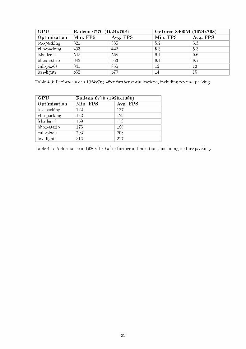
GPU Radeon 6770 (1024x768) GeForce 8400M (1024x768)
Optimization Min. FPS Avg. FPS Min. FPS Avg. FPS
tex-packing 321 335 5.2 5.3
vbo-packing 433 442 5.3 5.3
fshader-if 542 568 9.4 9.6
bbox-attrib 643 653 9.4 9.7
cull-pixels 841 855 13 13
less-lights 852 870 14 15
Table 4.3: Performance in 1024x768 after further optimizations, including texture packing.
GPU Radeon 6770 (1920x1080)
Optimization Min. FPS Avg. FPS
tex-packing 122 127
vbo-packing 132 139
fshader-if 169 173
bbox-attrib 175 180
cull-pixels 203 208
less-lights 213 217
Table 4.4: Performance in 1920x1080 after further optimizations, including texture packing.
25
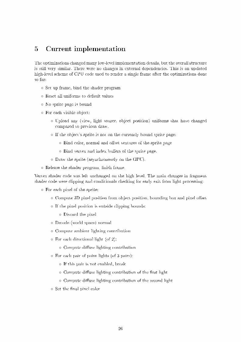
5 Current implementation
The optimizations changed many low-level implementation details, but the overall structureis still very similar. There were no changes in external dependencies. This is an updatedhigh-level scheme of CPU code used to render a single frame after the optimizations doneso far:
∘ Set up frame, bind the shader program
∘ Reset all uniforms to default values
∘ No sprite page is bound
∘ For each visible object:
∘ Upload any (view, light source, object position) uniforms that have changedcompared to previous draw.
∘ If the object’s sprite is not on the currently bound sprite page:
∘ Bind color, normal and offset textures of the sprite page
∘ Bind vertex and index buffers of the sprite page.
∘ Draw the sprite (asynchronously on the GPU).
∘ Release the shader program, finish frame.
Vertex shader code was left unchanged on the high level. The main changes in fragmentshader code were clipping and conditionals checking for early exit from light processing:
∘ For each pixel of the sprite:
∘ Compute 3D pixel position from object position, bounding box and pixel offset
∘ If the pixel position is outside clipping bounds:
∘ Discard the pixel
∘ Decode (world-space) normal
∘ Compute ambient lighting contribution
∘ For each directional light (of 2):
∘ Compute diffuse lighting contribution
∘ For each pair of point lights (of 3 pairs):
∘ If this pair is not enabled, break
∘ Compute diffuse lighting contribution of the first light
∘ Compute diffuse lighting contribution of the second light
∘ Set the final pixel color
26
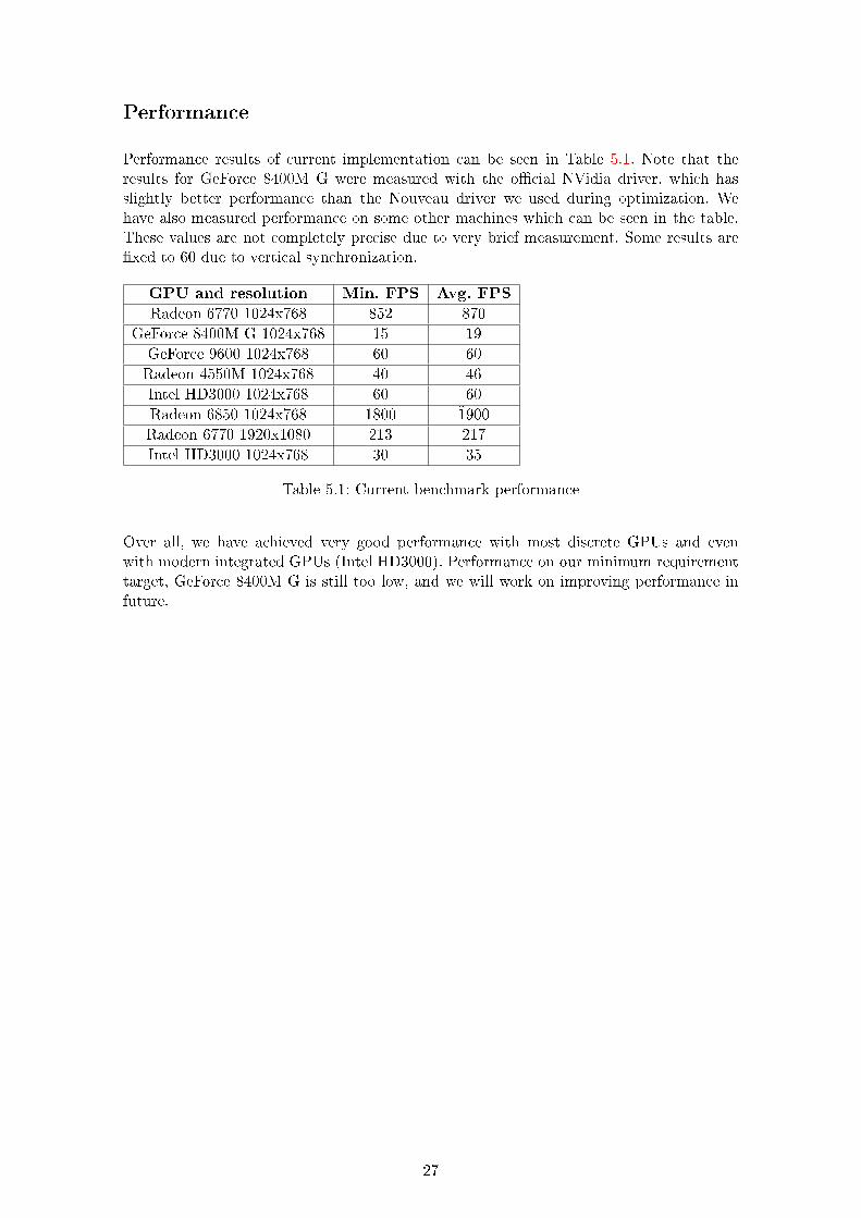
Performance
Performance results of current implementation can be seen in Table 5.1. Note that theresults for GeForce 8400M G were measured with the official NVidia driver, which hasslightly better performance than the Nouveau driver we used during optimization. Wehave also measured performance on some other machines which can be seen in the table.These values are not completely precise due to very brief measurement. Some results arefixed to 60 due to vertical synchronization.
GPU and resolution Min. FPS Avg. FPS
Radeon 6770 1024x768 852 870
GeForce 8400M G 1024x768 15 19
GeForce 9600 1024x768 60 60
Radeon 4550M 1024x768 40 46
Intel HD3000 1024x768 60 60
Radeon 6850 1024x768 1800 1̃900
Radeon 6770 1920x1080 213 217
Intel HD3000 1024x768 30 35
Table 5.1: Current benchmark performance
Over all, we have achieved very good performance with most discrete GPUs and evenwith modern integrated GPUs (Intel HD3000). Performance on our minimum requirementtarget, GeForce 8400M G is still too low, and we will work on improving performance infuture.
27

6 Conclusion
We have presented a method to achieve real-time 3D-like lighting in 2D graphics, and im-plemented a basic open-source pre-renderer tool capable of creating sprites for our lightingmodel. The pre-renderer still has some shortcomings, however:
∘ Only single-mesh models are supported.
∘ Animations are not supported.
∘ Every image is written to a separate file; there are no sprite sheets.
All of these features will have to be implemented in future for use in our future projects,but they are not directly related to lighting.
A basic lighting demo is also implemented, with diffuse lighting based on the Blinn-Phongmodel. However, due to hardware limitations, only a fixed number of lights is supported.Specular lighting is not implemented to increase performance on old hardware; it might beimplemented in future as an optional feature for (relatively) modern machines.
In future we plan to focus on light source virtualization (to work around the fixed lightcount) and possibly extensions to the light model such as self-shadowing and HDR.
There are also many options for further work; e.g. ways to represent pre-rendered datamore efficiently and alternative 2D lighting models.
Bibliography
[1] James F. Blinn. Models of light reflection for computer synthesized pictures. SIGG-
RAPH Comput. Graph., 11(2):192–198, July 1977.
[2] James F. Blinn. Simulation of wrinkled surfaces. SIGGRAPH Comput. Graph.,12(3):286–292, August 1978.
[3] P. Cignoni, C. Montani, R. Scopigno, and C. Rocchini. A general method for preservingattribute values on simplified meshes. In Proceedings of the conference on Visualization
’98, VIS ’98, pages 59–66, Los Alamitos, CA, USA, 1998. IEEE Computer Society Press.
[4] Mark Harris and Ian Buck. Gpu flow-control idioms. In Matt Pharr, editor, GPU Gems
2, pages 547–555. Addison-Wesley, 2005.
[5] Bui Tuong Phong. Illumination for computer generated pictures. Commun. ACM,18(6):311–317, June 1975.
[6] Video game costs [online]. [Retrieved 2013-04-17] Available on the internet:http://vgsales.wikia.com/wiki/Video_game_costs
[7] Westwood Studios. 1999. Command & Conquer: Tiberian Sun (computer game)
[8] Appeal. 1999. Outcast (computer game)
[9] Westwood Studios. 2000. Command & Conquer: Red Alert 2 (computer game)
[10] Markus Persson. 2009. Minecraft (computer game)
28

[11] Interplay Entertainment. 1997. Fallout (computer game)
[12] Maxis. 2003. SimCity4 (computer game)
[13] BioWare. 1998. Baldur’s Gate (computer game)
[14] D-Grafix Design. 2006. SpriteForge. [online] [Retrieved 2013-04-17]Available on the internet: http://www.d-grafix.com/?page=spriteforge
[15] TheGameCreators. SpriteMe. [online] [Retrieved 2013-04-17] Available on the internet:http://www.thegamecreators.com/?m=view_product&id=2301
[16] D programming language [online]. [Retrieved 2013-04-24] Available on the internet:http://dlang.org
[17] Derelict [online]. [Retrieved 2013-04-24] Available on the internet:https://github.com/aldacron/Derelict3
[18] SDL (Simple DirectMedia Layer) [online]. [Retrieved 2013-04-24] Available on theinternet: http://libsdl.org
[19] David Herberth. Gl3n [online]. [Retrieved 2013-04-24] Available on the internet:http://dav1dde.github.io/gl3n/
[20] ApiTrace [online]. [Retrieved 2013-04-24] Available on the internet:http://apitrace.github.io/
[21] GeForce 8400M G benchmarks [online].[Retrieved 2013-04-24] Available on the inter-net: http://www.notebookcheck.net/NVidia-GeForce-8400M-G.3710.0.html
[22] Jim Scott. Packing Lightmaps [online]. [Retrieved 2013-04-25] Available on the inter-net: http://www.blackpawn.com/texts/lightmaps/default.html
29