Embed Size (px)
Citation preview
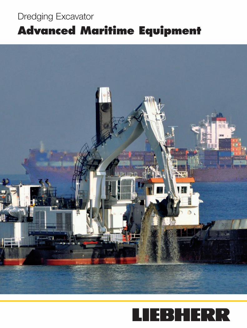
Dredging Excavator
Advanced Maritime Equipment
Dredging Excavator2
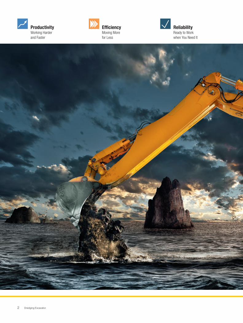
Productivity Working Harder and Faster
Efficiency Moving More for Less
Reliability Ready to Workwhen You Need It
Dredging Excavator 3
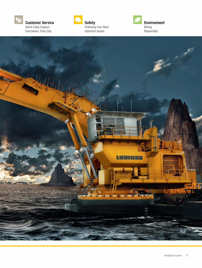
Customer Service World-Class Support,Everywhere, Every Day
SafetyProtecting Your MostImportant Assets
EnvironmentMining Responsibly
Dredging Excavator4
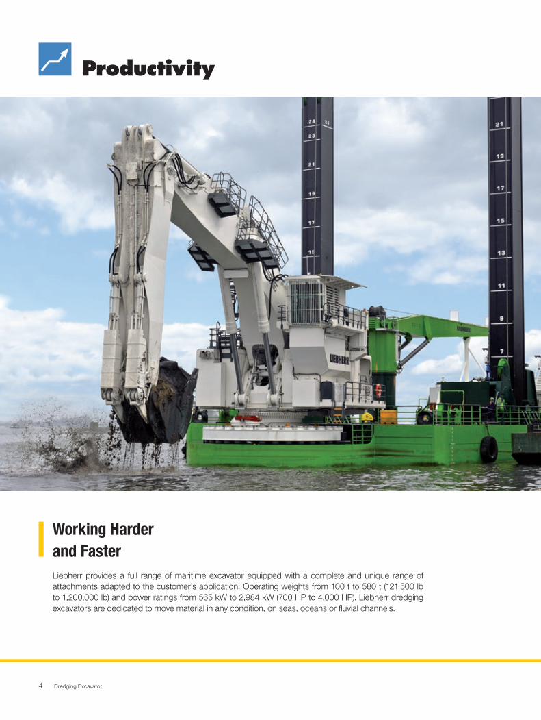
Productivity
Liebherr provides a full range of maritime excavator equipped with a complete and unique range of attachments adapted to the customer’s application. Operating weights from 100 t to 580 t (121,500 lb to 1,200,000 lb) and power ratings from 565 kW to 2,984 kW (700 HP to 4,000 HP). Liebherr dredging excavators are dedicated to move material in any condition, on seas, oceans or fluvial channels.
Working Harder and Faster
Dredging Excavator 5
Hydraulic Dredging Control SystemThe power of the hydraulic technology combined with the high precision from the electronic control contribute to pro-mote energy optimization. The high pressure of the hydraulic excavator system can be used by the barge to offer a unique-ly powerful hydraulic source.
Optimized Cycle TimesThe Liebherr dredging excavator is equiped with a Close-Loop Swing Circuit. Contrary to machines using open hy-draulic circuits, this enables the maximum swing torque whilst retaining the full oil flow for the attachment movement. The use of an independent swing circuit results in faster arm motions even during swing movements contributing to faster cycle times. The mode selector enables the operator to ad-just the machine power to match the application for the best performances.
High Digging ForcesDesigned for high-performing mechanical force distribution, the production-tailored attachment delivers high digging and lifting forces. Integrating Liebherr made cylinders, the Liebherr dredging excavator attachment ensures the highest crowd and breakout forces to perform even in the most de-manding and intensive job conditions.
Precise Machine MotionsLiebherr dredging excavators design integrates the Litronic Plus electronic control system to allow for easy control even when simultaneous movements are required. The patented Liebherr electronic damping system provides controlled end-cushioning for smooth attachment motions.
Engineeredfor Maritime Applications
Performanceand Accuracy
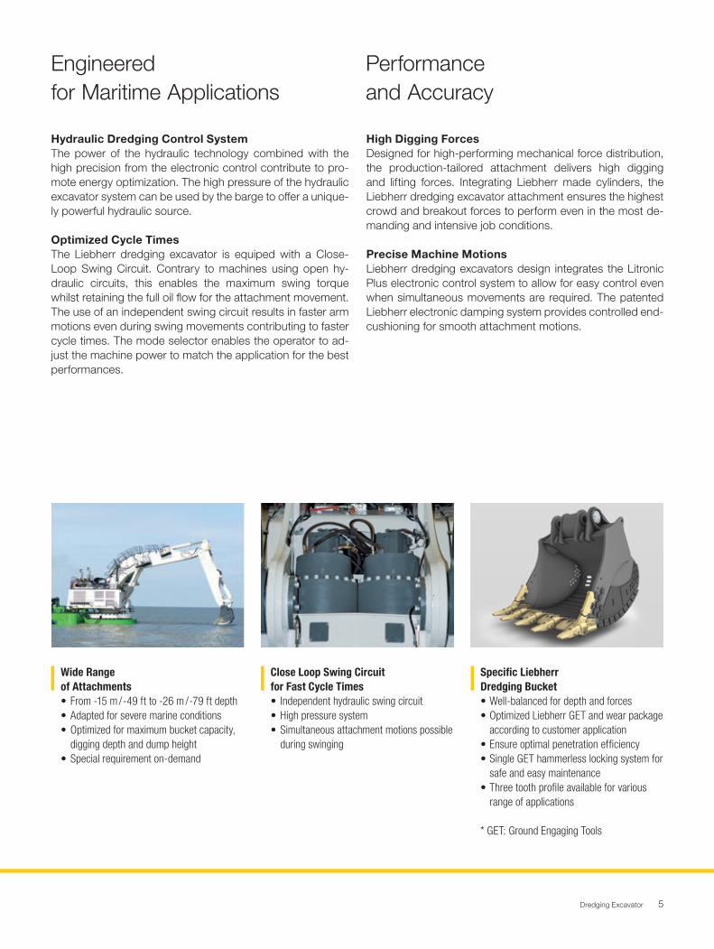
Wide Range of Attachments• From -15 m / -49 ft to -26 m / -79 ft depth• Adapted for severe marine conditions• Optimized for maximum bucket capacity,
digging depth and dump height• Special requirement on-demand
Close Loop Swing Circuitfor Fast Cycle Times• Independent hydraulic swing circuit• High pressure system• Simultaneous attachment motions possible
during swinging
Specific LiebherrDredging Bucket • Well-balanced for depth and forces • Optimized Liebherr GET and wear package according to customer application • Ensure optimal penetration efficiency • Single GET hammerless locking system for safe and easy maintenance • Three tooth profile available for various range of applications
* GET: Ground Engaging Tools
Dredging Excavator6
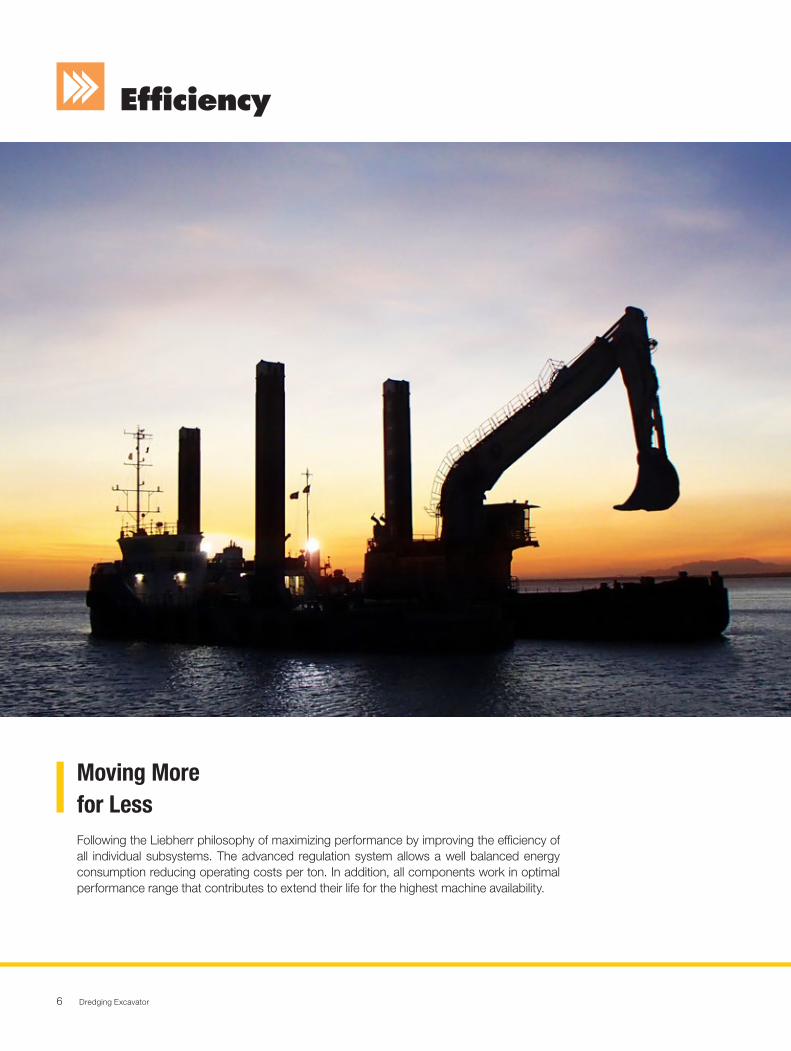
Efficiency
Following the Liebherr philosophy of maximizing performance by improving the efficiency of all individual subsystems. The advanced regulation system allows a well balanced energy consumption reducing operating costs per ton. In addition, all components work in optimal performance range that contributes to extend their life for the highest machine availability.
Moving More for Less
Dredging Excavator 7
Pontoon Hydraulic Oil SupplyAssuming hydraulic excavators and pontoon vessels are fully integrated systems, hydraulic powerpacks supply hydraulic oil for pontoon vessel consumers through the hydraulic ex-cavator rotary connection.
Independent Cooling SystemOil and water cooling fans are independent and electronically managed. The on-demand cooling control enables to maxi-mize available power for the working process. This technolo-gy contributes to maintain sustainable temperature of all the hydraulic components extending their life.
Litronic PlusThe Liebherr-patented Litronic Plus system consists of an in-telligent power management system specially developed to optimize electrical, mechanical and hydraulic power distribu-tion. This system encourages fuel efficiency and energy sav-ings while ensuring peak subsystem performance according to immediate working requirements.
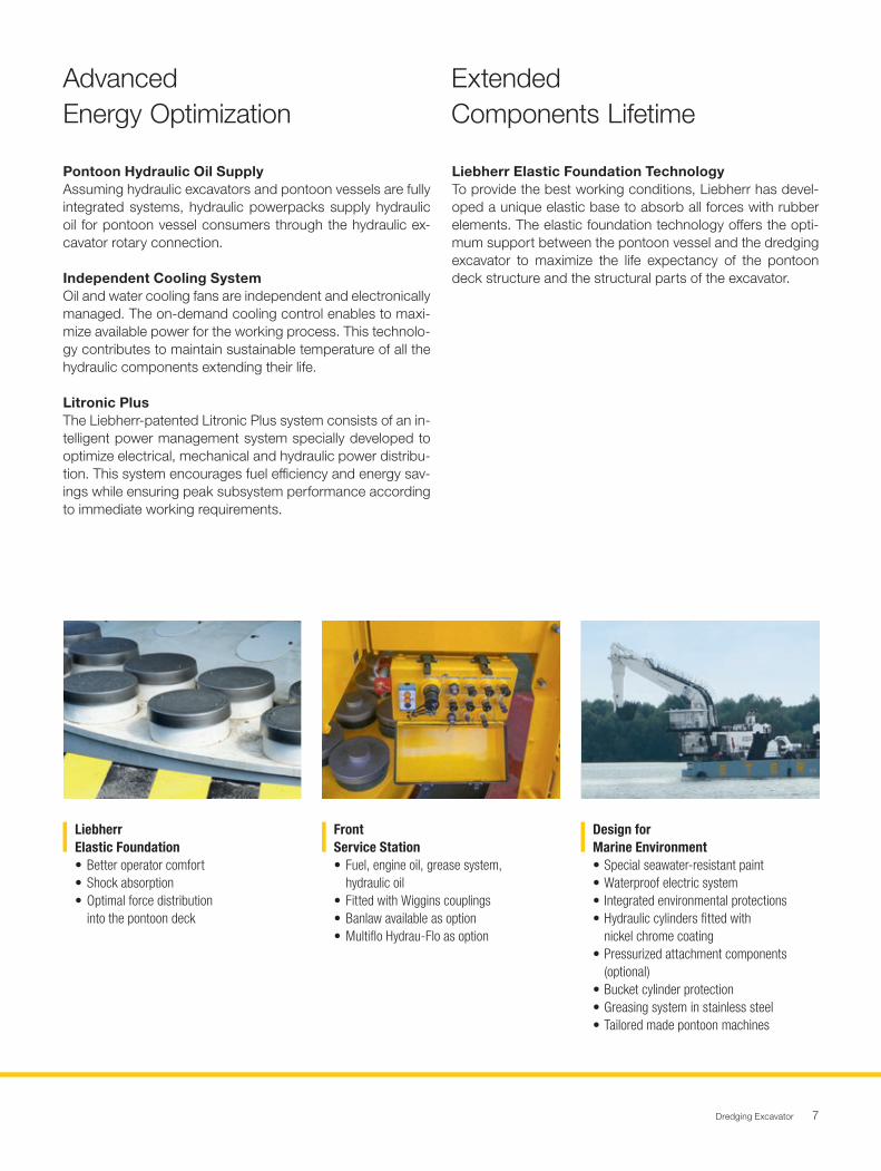
Liebherr Elastic Foundation TechnologyTo provide the best working conditions, Liebherr has devel-oped a unique elastic base to absorb all forces with rubber elements. The elastic foundation technology offers the opti-mum support between the pontoon vessel and the dredging excavator to maximize the life expectancy of the pontoon deck structure and the structural parts of the excavator.
AdvancedEnergy Optimization
ExtendedComponents Lifetime
Liebherr Elastic Foundation• Better operator comfort• Shock absorption• Optimal force distribution
into the pontoon deck
FrontService Station• Fuel, engine oil, grease system,
hydraulic oil• Fitted with Wiggins couplings• Banlaw available as option• Multiflo Hydrau-Flo as option
Design forMarine Environment • Special seawater-resistant paint• Waterproof electric system• Integrated environmental protections• Hydraulic cylinders fitted with nickel chrome coating• Pressurized attachment components (optional)• Bucket cylinder protection• Greasing system in stainless steel • Tailored made pontoon machines
Dredging Excavator8
Reliability
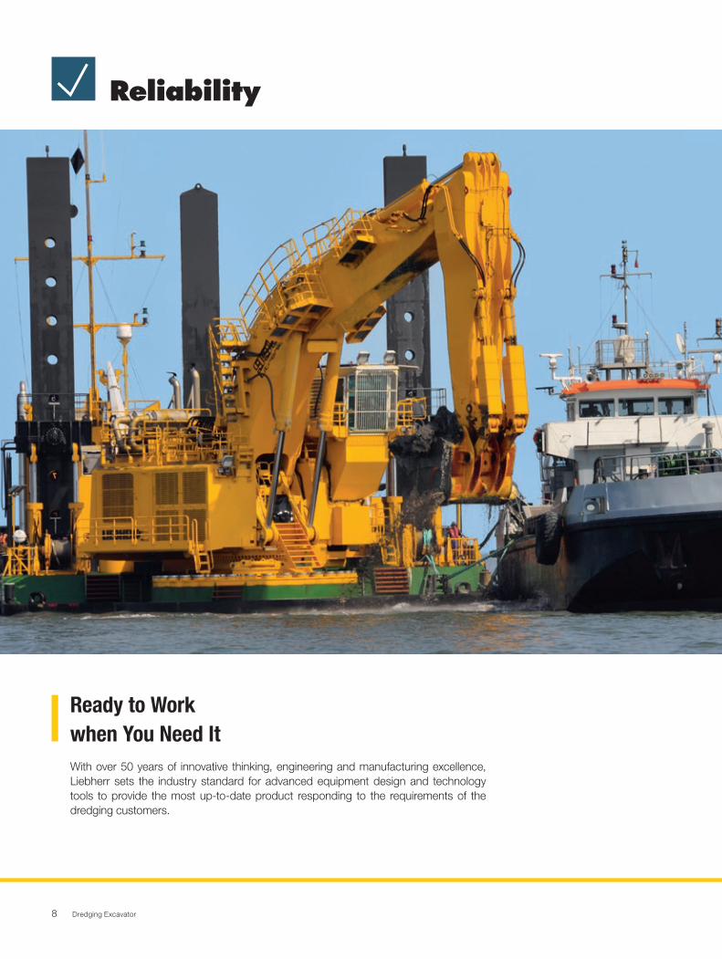
With over 50 years of innovative thinking, engineering and manufacturing excellence, Liebherr sets the industry standard for advanced equipment design and technology tools to provide the most up-to-date product responding to the requirements of the dredging customers.
Ready to Workwhen You Need It
Dredging Excavator 9
Liebherr Component IntegrationAs an OEM, Liebherr has built a solid reputation for its de-velopment and production of high quality strategic mining components. The Liebherr dredging excavators integrate ro-bust and reliable mining optimized components that are de-veloped, manufactured and controlled by Liebherr ensuring reliability and high performance for the entire machine.
Advanced Hydraulic Oil FiltrationThe hydraulic oil filtration systems remove fluid contaminants to offer the highest rate of hydraulic components durabili-ty. To maintain oil quality, all return hydraulic oil flow goes through a fine filtration system (15 / 5 μm) and oil tank is sized to considerably extend the time between service intervals.
Quality Management Continuous ImprovementLiebherr quality begins during machine design and simula-tions. Liebherr meets the highest standards for special selec-tions of steels and casting materials. Based on the expertise of certified internal auditors and a highly qualified workforce, all manufacturing process steps are devised to provide the most comprehensive control, monitoring and traceability. Liebherr-Mining Equipment Colmar SAS is ISO 9001 certified.
Liebherr sales engineer support during the decision-making stage guarantees that the customised product choice per-fectly matches customer requirements. To ensure customer satisfaction, the Liebherr products are available in a range of specific configurations. For example, to upgrade the machine for the cold climate environment, to adapt the attachment for an specific application or to increase safety and comfort of the operator. With more than 150 engineers dedicated to develop mining and maritime excavators, Liebherr offers tai-lored-made solution to meet the clients requirements.
Quality:the Liebherr Trademark
Suit CustomerRequirements
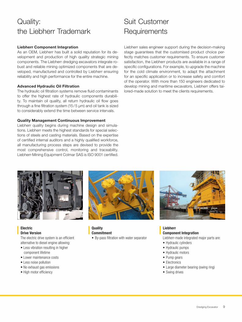
Electric Drive VersionThe electric drive system is an efficientalternative to diesel engine allowing:• Less vibration resulting in higher
component lifetime• Lower maintenance costs• Less noise pollution• No exhaust gas emissions• High motor efficiency
QualityCommitment• By-pass filtration with water separator
LiebherrComponent Integration Liebherr-made integrated major parts are:• Hydraulic cylinders• Hydraulic pumps• Hydraulic motors• Pump gears• Electronics• Large diameter bearing (swing ring)• Swing drives
Dredging Excavator10
Customer Service
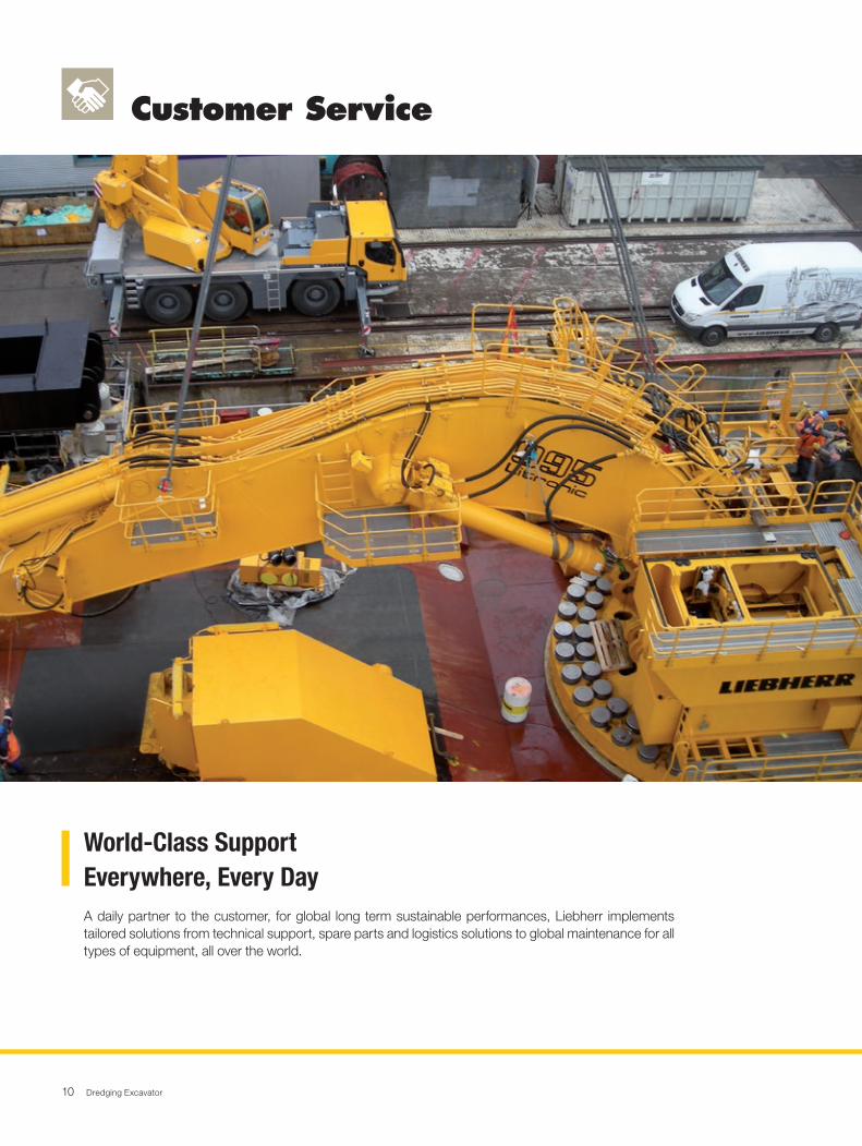
A daily partner to the customer, for global long term sustainable performances, Liebherr implements tailored solutions from technical support, spare parts and logistics solutions to global maintenance for all types of equipment, all over the world.
World-Class SupportEverywhere, Every Day
Dredging Excavator 11
Customer Service
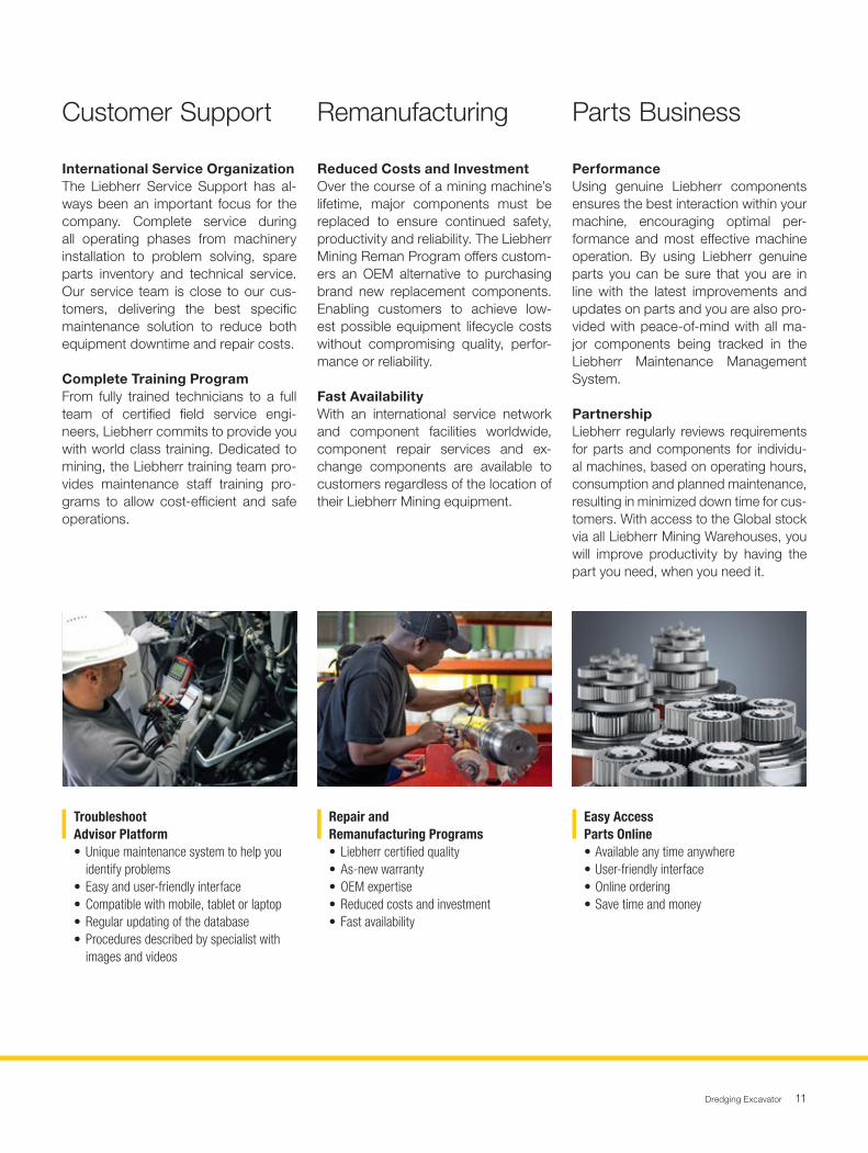
International Service OrganizationThe Liebherr Service Support has al-ways been an important focus for the company. Complete service during all operating phases from machinery installation to problem solving, spare parts inventory and technical service. Our service team is close to our cus-tomers, delivering the best specific maintenance solution to reduce both equipment downtime and repair costs.
Complete Training ProgramFrom fully trained technicians to a full team of certified field service engi-neers, Liebherr commits to provide you with world class training. Dedicated to mining, the Liebherr training team pro-vides maintenance staff training pro-grams to allow cost-efficient and safe operations.
Reduced Costs and InvestmentOver the course of a mining machine’s lifetime, major components must be replaced to ensure continued safety, productivity and reliability. The Liebherr Mining Reman Program offers custom-ers an OEM alternative to purchasing brand new replacement components. Enabling customers to achieve low-est possible equipment lifecycle costs without compromising quality, perfor-mance or reliability.
Fast AvailabilityWith an international service network and component facilities worldwide, component repair services and ex-change components are available to customers regardless of the location of their Liebherr Mining equipment.
PerformanceUsing genuine Liebherr components ensures the best interaction within your machine, encouraging optimal per-formance and most effective machine operation. By using Liebherr genuine parts you can be sure that you are in line with the latest improvements and updates on parts and you are also pro-vided with peace-of-mind with all ma-jor components being tracked in the Liebherr Maintenance Management System.
PartnershipLiebherr regularly reviews requirements for parts and components for individu-al machines, based on operating hours, consumption and planned maintenance, resulting in minimized down time for cus-tomers. With access to the Global stock via all Liebherr Mining Warehouses, you will improve productivity by having the part you need, when you need it.
Customer Support Remanufacturing Parts Business
Troubleshoot Advisor Platform• Unique maintenance system to help you
identify problems• Easy and user-friendly interface• Compatible with mobile, tablet or laptop• Regular updating of the database• Procedures described by specialist with
images and videos
Repair andRemanufacturing Programs• Liebherr certified quality• As-new warranty• OEM expertise• Reduced costs and investment• Fast availability
Easy AccessParts Online • Available any time anywhere• User-friendly interface• Online ordering• Save time and money
Dredging Excavator12
Safety
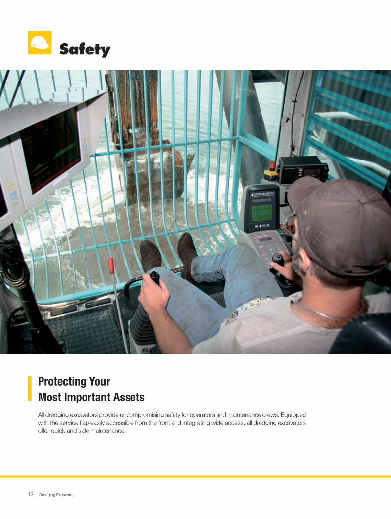
All dredging excavators provide uncompromising safety for operators and maintenance crews. Equipped with the service flap easily accessible from the front and integrating wide access, all dredging excavators offer quick and safe maintenance.
Protecting Your Most Important Assets
Dredging Excavator 13
Safety
Safety-First Cab DesignThe extra-large dredging cab offers ideal working conditions. Designed with a one-piece windscreen, the cab supplies large panoramic windows providing an outstanding visibil-ity over the whole equipment. Two outside cameras allow a 360° view around the equipment. Long-distance lighting allows the operator to properly view his area of work for the most efficient loading.
Secure MaintenanceAll components have been located allowing effortless in-spection and replacement. Numerous service lights are strategically located in the service areas to sustain suitable maintenance conditions, day or night. Emergency stops have been strategically placed in the cab, engine compartment and at the front service station. The Liebherr dredging exca-vators eliminate hazards to ensure a safe environment for the service staff during maintenance.
Automatic Fire Suppression SystemThe Liebherr dredging excavators can be equipped with a fully integrated fire suppression, employing a dual agent solu-tion to prevent and protect the machine. The fire suppression system has both automatic and manual release capabilities, emergency stop devices are strategically located on the ma-chine to be easily accessible in any case by the operator.
Defences to the Initiation of FireThe engine compartment integrates a bulkhead wall that separates the engine from the hydraulic pumps. This reduc-es the risk of hydraulic oil entering the engine compartment. The turbochargers and exhaust systems are heat shielded, and all the hydraulic hoses are made from a highly resistant material to prevent the risk of fires.
Safety-FirstWorking Conditions
EfficientMachine Protection
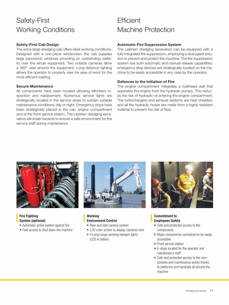
Fire Fighting System (optional)• Automatic active system against fire• Fast access to shut down the machine
WorkingEnvironment Control• Rear and side camera system• LCD color screen to display cameras view• 4 Long-range working halogen lights
(LED in option)
Commitment toEmployees Safety • Safe and protected access to the
components• Major components centralized to be easily accessible• Front service station• E-stops located for the operator and
maintenance staff• Safe and protected access to the com-
ponents and maintenance points thanks to platforms and handrails all around the machine
Dredging Excavator14
Environment
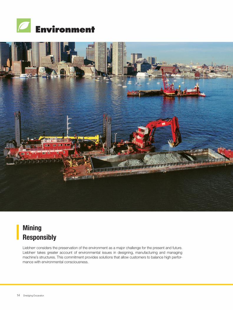
Liebherr considers the preservation of the environment as a major challenge for the present and future. Liebherr takes greater account of environmental issues in designing, manufacturing and managing machine’s structures. This commitment provides solutions that allow customers to balance high perfor-mance with environmental consciousness.
MiningResponsibly
Dredging Excavator 15
Environment
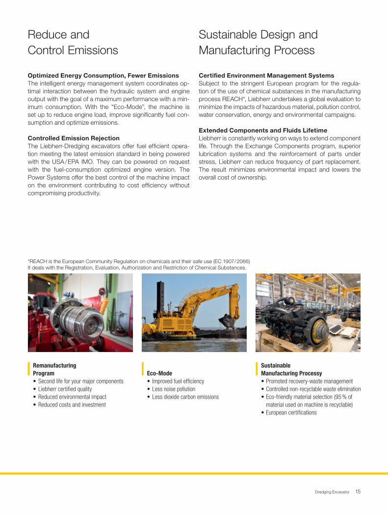
Optimized Energy Consumption, Fewer EmissionsThe intelligent energy management system coordinates op-timal interaction between the hydraulic system and engine output with the goal of a maximum performance with a min-imum consumption. With the “Eco-Mode”, the machine is set up to reduce engine load, improve significantly fuel con-sumption and optimize emissions.
Controlled Emission RejectionThe Liebherr-Dredging excavators offer fuel efficient opera-tion meeting the latest emission standard in being powered with the USA / EPA IMO. They can be powered on request with the fuel-consumption optimized engine version. The Power Systems offer the best control of the machine impact on the environment contributing to cost efficiency without compromising productivity.
Certified Environment Management SystemsSubject to the stringent European program for the regula-tion of the use of chemical substances in the manufacturing process REACH*, Liebherr undertakes a global evaluation to minimize the impacts of hazardous material, pollution control, water conservation, energy and environmental campaigns.
Extended Components and Fluids LifetimeLiebherr is constantly working on ways to extend component life. Through the Exchange Components program, superior lubrication systems and the reinforcement of parts under stress, Liebherr can reduce frequency of part replacement. The result minimizes environmental impact and lowers the overall cost of ownership.
Reduce andControl Emissions
Sustainable Design andManufacturing Process
Remanufacturing Program• Second life for your major components• Liebherr certified quality• Reduced environmental impact• Reduced costs and investment
Eco-Mode• Improved fuel efficiency• Less noise pollution• Less dioxide carbon emissions
SustainableManufacturing Processy • Promoted recovery-waste management• Controlled non-recyclable waste elimination• Eco-friendly material selection (95 % of material used on machine is recyclable)• European certifications
*REACH is the European Community Regulation on chemicals and their safe use (EC 1907/ 2066)It deals with the Registration, Evaluation, Authorization and Restriction of Chemical Substances.
Dredging Excavator16
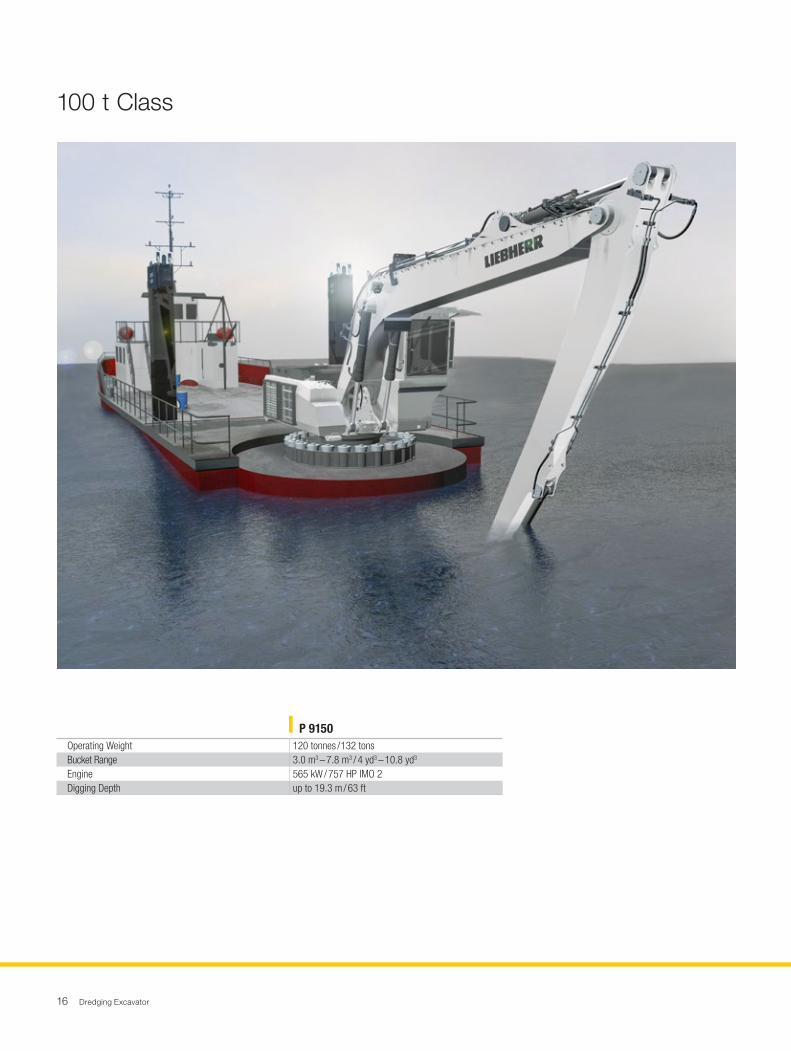
100 t Class
P 9150Operating Weight 120 tonnes / 132 tonsBucket Range 3.0 m3 – 7.8 m3 / 4 yd3 – 10.8 yd3
Engine 565 kW / 757 HP IMO 2Digging Depth up to 19.3 m / 63 ft
Dredging Excavator 17
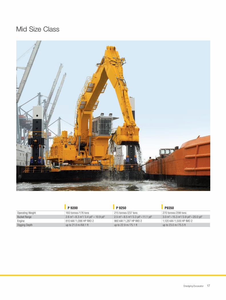
Mid Size Class
P 9200 P 9250 P9350Operating Weight 160 tonnes / 176 tons 215 tonnes / 237 tons 270 tonnes / 298 tonsBucket Range 2.6 m3 – 8.3 m3 / 3.4 yd3 – 10.9 yd3 2.5 m3 – 8.5 m3 / 3.3 yd3 – 11.1 yd3 3.0 m3 – 15.3 m3 / 3.9 yd3 – 20.0 yd3
Engine 810 kW / 1,086 HP IMO 2 960 kW / 1,287 HP IMO 2 1,120 kW / 1,500 HP IMO 2Digging Depth up to 21.0 m / 68.1 ft up to 22.9 m / 75.1 ft up to 23.0 m / 75.5 ft
Dredging Excavator18
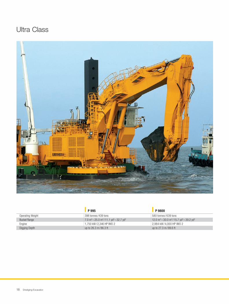
Ultra Class
P 995 P 9800Operating Weight 398 tonnes / 439 tons 580 tonnes / 639 tonsBucket Range 7.0 m3 – 25.0 m3 / 11.1 yd3 – 32.7 yd3 12.0 m3 – 30.0 m3 / 15.7 yd3 – 39.2 yd3
Engine 1,750 kW / 2,346 HP IMO 2 2,984 kW / 4,000 HP IMO 2Digging Depth up to 26.3 m / 86.3 ft up to 27.3 m / 89.6 ft
Dredging Excavator 19
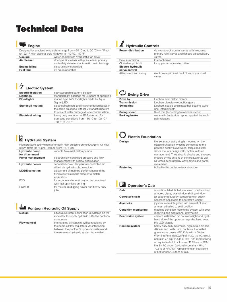
Swing DriveDrive by Liebherr axial piston motorsTransmission Liebherr planetary reduction gearsSwing ring Liebherr, sealed single race ball bearing swing
ring, internal teethSwing speed 0 – 6 rpm (according to machine model)Parking brake wet multi-disc brakes, spring applied, hydrauli-
cally released
Pontoon Hydraulic Oil SupplyDesign a hydraulic rotary connection is installed on the
excavator to supply hydraulic oil to the pontoon consumers
Flow control the required oil capacity will be regulated by the pump oil flow regulators. An interfacing between the pontoon’s hydraulic system and the excavator hydraulic system is provided
Electric SystemElectric isolation easy accessible battery isolationLightings standard light package for 24 hours of operationFloodlights marine type 24 V floodlights made by Aqua
Signal (LED)Standstill heating electrical cabinets and instrumentation boxes in
the cabin equipped with 24 V standstill heaters to prevent water damage due to condensation
Electrical wiring heavy duty execution in IP65 standard for operating conditions from – 50 °C to 100 °C / – 58 °F to 212 °F
Hydraulic SystemHigh pressure safety filters after each high pressure pump (200 μm), full flow return filters (15 / 5 μm), leak oil filters (15 / 5 μm)Hydraulic pump for attachment
variable flow axial piston pumps
Pump management electronically controlled pressure and flow management with oil flow optimisation
Hydraulic cooler separated cooler, temperature controlled fan driven via hydraulic piston motors
MODE selection adjustment of machine performance and the hydraulics via a mode selector to match application
ECO for economical operation (can be combined with fuel optimized setting)
POWER for maximum digging power and heavy duty jobs
EngineDesigned for ambient temperature range from – 20 °C up to 50 °C / – 4 °F up to 122 °F (with optional cold kit down to – 40 °C / – 40 °F)Cooling water-cooled with hydrostatic fan driveAir cleaner dry-type air cleaner with pre-cleaner, primary
and safety elements, automatic dust dischargeEngine idling electronically controlledFuel tank 26 hours operation
Hydraulic ControlsPower distribution via monoblock control valves with integrated
primary relief valves and flanged on secondary valves
Flow summation to attachmentClosed-loop circuit for uppercarriage swing driveElectro-hydraulic servo controlAttachment and swing electronic optimized control via proportional
valves
Elastic FoundationDesign the excavator swing ring is mounted on the
elastic foundation which is connected to the pontoon deck via oversized, torque resistant shock mounts designed for optimum force management. They absorb shocks and stresses created by the actions of the excavator as well as forces generated by wave action and barge movement
Fastening bolted to the pontoon deck structure
Operator’s CabCab sound insulated, tinted windows. Front window
armored glass, side window sliding windowOperator’s seat air suspended, body-contoured with shock
absorber, adjustable to operator’s weightJoysticks joystick levers integrated into armrest of seat,
armrest adjusted to seat positionCondition monitoring machine condition monitoring system with error
reporting and operational informationRear vision system camera installation on counterweight and right-
hand side of the uppercarriage displayed over the LCD- display
Heating system heavy duty, fully automatic, high output air con-ditioner and heater unit, contains fluorinated greenhouse gases HFC 134a with a Global Warming Potential (GWP) of 1430, the AC circuit contains 7.5 kg / 16.5 lb of HFC-134 representing an equivalent of 10.7 tonnes / 11.6 tons of CO2, the 2nd AC circuit (optional) contains 4.8 kg / 10.6 lb of HFC-134 representing an equivalent of 6.9 tonnes / 7.6 tons of CO2
Technical Data
20 Dredging Excavator
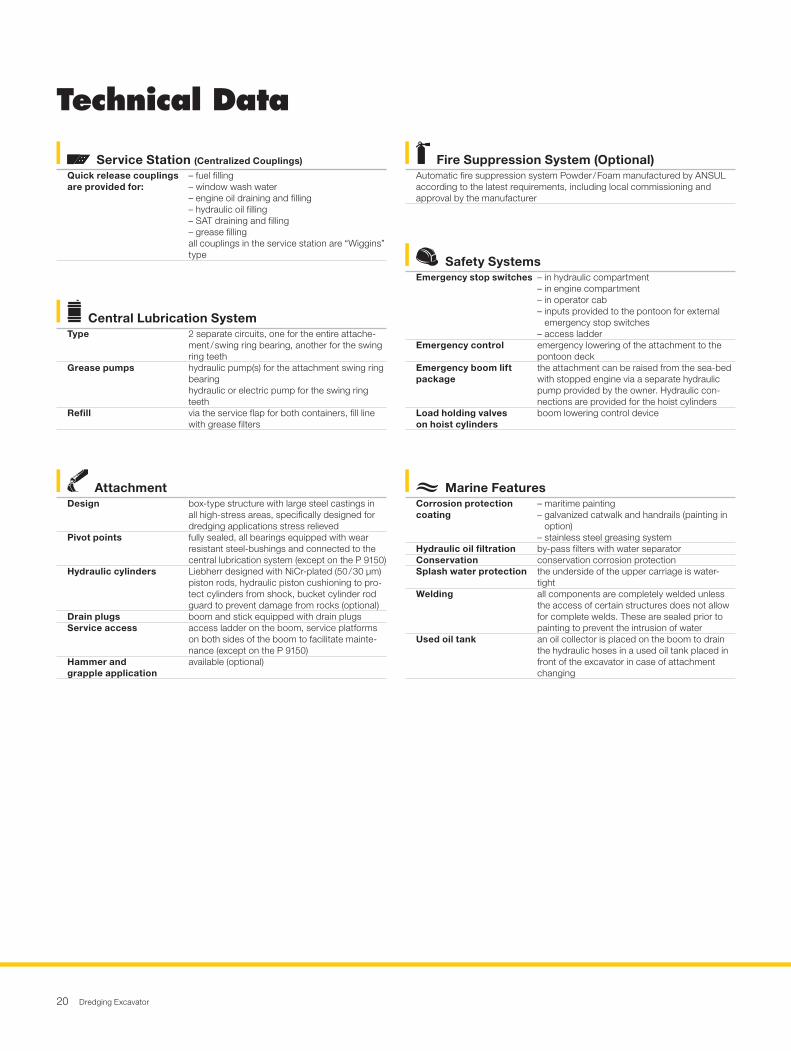
Marine FeaturesCorrosion protection coating
– maritime painting– galvanized catwalk and handrails (painting in
option)– stainless steel greasing system
Hydraulic oil filtration by-pass filters with water separatorConservation conservation corrosion protectionSplash water protection the underside of the upper carriage is water-
tightWelding all components are completely welded unless
the access of certain structures does not allow for complete welds. These are sealed prior to painting to prevent the intrusion of water
Used oil tank an oil collector is placed on the boom to drain the hydraulic hoses in a used oil tank placed in front of the excavator in case of attachment changing
Safety SystemsEmergency stop switches – in hydraulic compartment
– in engine compartment– in operator cab– inputs provided to the pontoon for external
emergency stop switches– access ladder
Emergency control emergency lowering of the attachment to the pontoon deck
Emergency boom lift package
the attachment can be raised from the sea-bed with stopped engine via a separate hydraulic pump provided by the owner. Hydraulic con-nections are provided for the hoist cylinders
Load holding valves on hoist cylinders
boom lowering control device
AttachmentDesign box-type structure with large steel castings in
all high-stress areas, specifically designed for dredging applications stress relieved
Pivot points fully sealed, all bearings equipped with wear resistant steel-bushings and connected to the central lubrication system (except on the P 9150)
Hydraulic cylinders Liebherr designed with NiCr-plated (50 / 30 μm) piston rods, hydraulic piston cushioning to pro-tect cylinders from shock, bucket cylinder rod guard to prevent damage from rocks (optional)
Drain plugs boom and stick equipped with drain plugsService access access ladder on the boom, service platforms
on both sides of the boom to facilitate mainte-nance (except on the P 9150)
Hammer and grapple application
available (optional)
Central Lubrication SystemType 2 separate circuits, one for the entire attache-
ment / swing ring bearing, another for the swing ring teeth
Grease pumps hydraulic pump(s) for the attachment swing ring bearinghydraulic or electric pump for the swing ring teeth
Refill via the service flap for both containers, fill line with grease filters
Fire Suppression System (Optional)Automatic fire suppression system Powder / Foam manufactured by ANSUL according to the latest requirements, including local commissioning and approval by the manufacturer
Service Station (Centralized Couplings)
Quick release couplings are provided for:
– fuel filling– window wash water– engine oil draining and filling– hydraulic oil filling– SAT draining and filling– grease fillingall couplings in the service station are “Wiggins” type
Technical Data
Dredging Excavator 21
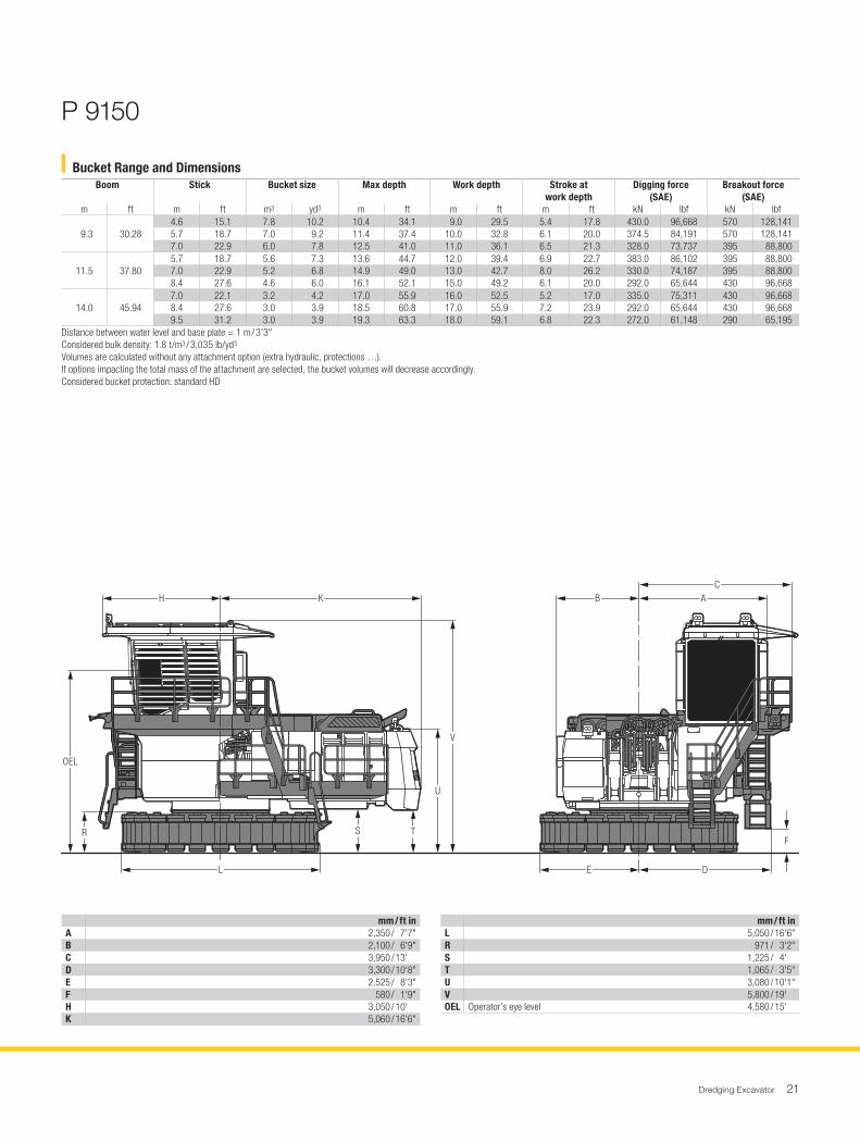
Bucket Range and DimensionsBoom Stick Bucket size Max depth Work depth Stroke at
work depthDigging force
(SAE)Breakout force
(SAE)m ft m ft m3 yd3 m ft m ft m ft kN lbf kN lbf
9.3 30.284.6 15.1 7.8 10.2 10.4 34.1 9.0 29.5 5.4 17.8 430.0 96,668 570 128,1415.7 18.7 7.0 9.2 11.4 37.4 10.0 32.8 6.1 20.0 374.5 84,191 570 128,1417.0 22.9 6.0 7.8 12.5 41.0 11.0 36.1 6.5 21.3 328.0 73,737 395 88,800
11.5 37.805.7 18.7 5.6 7.3 13.6 44.7 12.0 39.4 6.9 22.7 383.0 86,102 395 88,8007.0 22.9 5.2 6.8 14.9 49.0 13.0 42.7 8.0 26.2 330.0 74,187 395 88,8008.4 27.6 4.6 6.0 16.1 52.1 15.0 49.2 6.1 20.0 292.0 65,644 430 96,668
14.0 45.947.0 22.1 3.2 4.2 17.0 55.9 16.0 52.5 5.2 17.0 335.0 75,311 430 96,6688.4 27.6 3.0 3.9 18.5 60.8 17.0 55.9 7.2 23.9 292.0 65,644 430 96,6689.5 31.2 3.0 3.9 19.3 63.3 18.0 59.1 6.8 22.3 272.0 61,148 290 65,195
Distance between water level and base plate = 1 m / 3'3"Considered bulk density: 1.8 t/m3 / 3,035 lb/yd3
Volumes are calculated without any attachment option (extra hydraulic, protections …).If options impacting the total mass of the attachment are selected, the bucket volumes will decrease accordingly.Considered bucket protection: standard HD
OEL
R S T
U
V
F
E D
AH K BC
M0037L
P 9150
mm / ft inA 2,350 / 7'7"B 2,100 / 6'9"C 3,950 / 13' D 3,300 / 10'8"E 2,525 / 8'3"F 580 / 1'9"H 3,050 / 10' K 5,060 / 16'6"
mm / ft inL 5,050 / 16'6"R 971 / 3'2"S 1,225 / 4' T 1,065 / 3'5"U 3,080 / 10'1"V 5,800 / 19' OEL Operator’s eye level 4,580 / 15'

22 Dredging Excavator
Bucket Range and DimensionsBoom Stick Bucket size Max depth Work depth Stroke at
work depthDigging force
(SAE)Breakout force
(SAE)m ft m ft m3 yd3 m ft m ft m ft kN lbf kN lbf
14.0 45.11 5.0 16.4 8.3 10.9 14.0 48.2 12.0 39.4 5.6 21.7 566 127,242 466 104,761 6.7 23.3 7.0 9.2 15.4 53.1 14.0 49.2 6.9 22.1 474 106,559 514 115,552 8.5 36.1 5.9 7.7 17.2 59.0 16.0 52.5 7.3 27.9 390 87,675 514 115,552
16.0 52.50 6.7 21.1 5.2 6.8 17.3 59.0 16.0 52.5 6.4 21.3 474 106,559 514 115,552 8.5 27.1 4.2 5.5 19.0 65.3 18.0 59.0 6.5 25.3 395 88,800 522 117,35010.1 33.1 3.7 4.8 20.5 69.1 19.0 65.7 9.1 21.1 345 77,559 544 122,296
18.0 59.00 6.7 23.3 3.5 4.6 18.8 64.7 18.0 59.0 5.0 17.4 487 109,482 568 127,691 8.5 27.1 3.0 3.9 20.5 70.6 19.0 62.3 8.3 30.2 407 91,497 593 133,31210.1 33.1 2.6 3.4 22.0 74.9 21.0 68.1 7.3 28.2 356 80,032 622 139,831
Distance between water level and base plate = 1 m / 3'3"Considered bulk density: 1.8 t/m3 / 3,035 lb/yd3
Volumes are calculated without any attachment option (extra hydraulic, protections …).If options impacting the total mass of the attachment are selected, the bucket volumes will decrease accordingly.Considered bucket protection: standard HD
P 9200
OEL
R
S T
U
V
E D
AH K BC
M0038L
mm / ft inA 3,400 / 11'6"B 2,430 / 7'9"C 4,150 / 13'6"D 3,560 / 11'7"E 2,975 / 9'8"H 3,080 / 10'1"K 5,800 / 19'
mm / ft inL 6,295 / 20'6"R 750 / 2'5"S 1,350 / 4'4"T 1,290 / 4'2"U 3,570 / 11'7"V 6,530 / 21'4"OEL Operator’s eye level 5,350 / 15'5"
Dredging Excavator 23
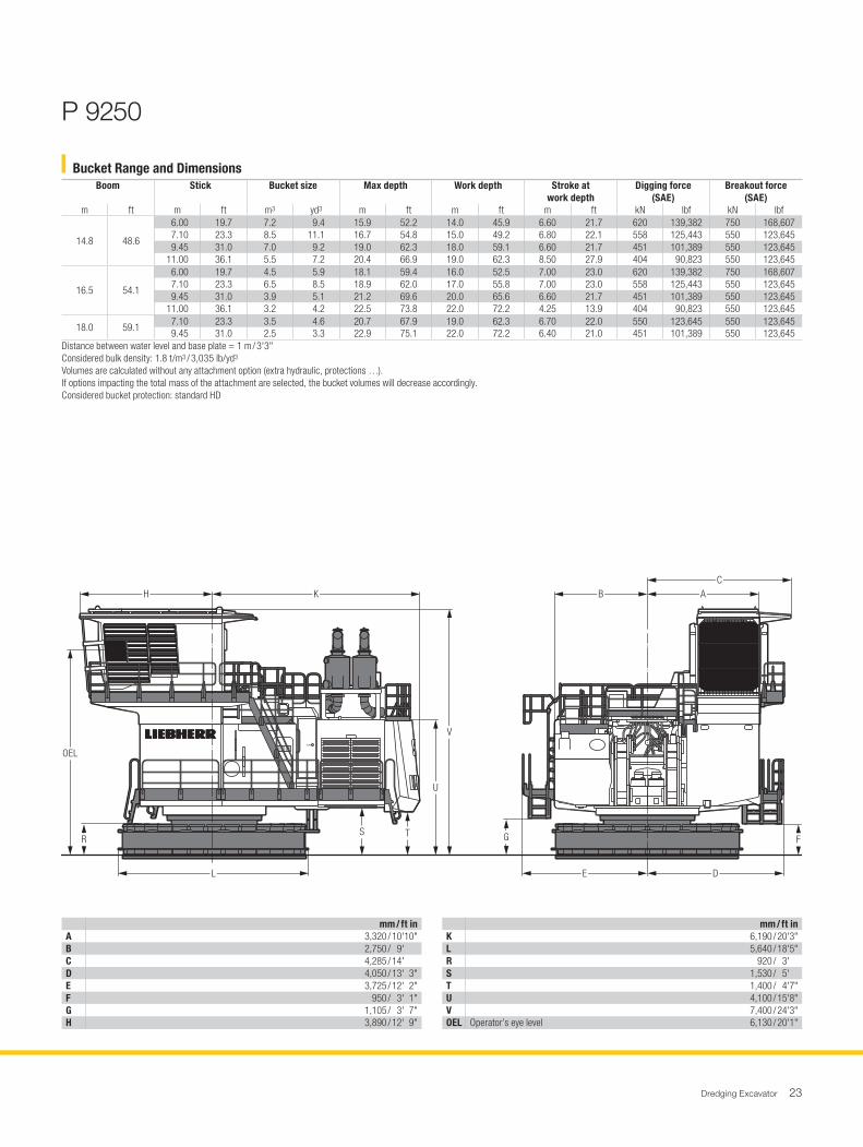
mm / ft inA 3,320 / 10'10"B 2,750 / 9' C 4,285 / 14' D 4,050 / 13' 3"E 3,725 / 12' 2"F 950 / 3' 1"G 1,105 / 3' 7"H 3,890 / 12' 9"
mm / ft inK 6,190 / 20'3"L 5,640 / 18'5"R 920 / 3' S 1,530 / 5' T 1,400 / 4'7"U 4,100 / 15'8"V 7,400 / 24'3"OEL Operator’s eye level 6,130 / 20'1"
Bucket Range and DimensionsBoom Stick Bucket size Max depth Work depth Stroke at
work depthDigging force
(SAE)Breakout force
(SAE)m ft m ft m3 yd3 m ft m ft m ft kN lbf kN lbf
14.8 48.6
6.00 19.7 7.2 9.4 15.9 52.2 14.0 45.9 6.60 21.7 620 139,382 750 168,607 7.10 23.3 8.5 11.1 16.7 54.8 15.0 49.2 6.80 22.1 558 125,443 550 123,645 9.45 31.0 7.0 9.2 19.0 62.3 18.0 59.1 6.60 21.7 451 101,389 550 123,64511.00 36.1 5.5 7.2 20.4 66.9 19.0 62.3 8.50 27.9 404 90,823 550 123,645
16.5 54.1
6.00 19.7 4.5 5.9 18.1 59.4 16.0 52.5 7.00 23.0 620 139,382 750 168,607 7.10 23.3 6.5 8.5 18.9 62.0 17.0 55.8 7.00 23.0 558 125,443 550 123,645 9.45 31.0 3.9 5.1 21.2 69.6 20.0 65.6 6.60 21.7 451 101,389 550 123,64511.00 36.1 3.2 4.2 22.5 73.8 22.0 72.2 4.25 13.9 404 90,823 550 123,645
18.0 59.1 7.10 23.3 3.5 4.6 20.7 67.9 19.0 62.3 6.70 22.0 550 123,645 550 123,645 9.45 31.0 2.5 3.3 22.9 75.1 22.0 72.2 6.40 21.0 451 101,389 550 123,645
Distance between water level and base plate = 1 m / 3'3"Considered bulk density: 1.8 t/m3 / 3,035 lb/yd3
Volumes are calculated without any attachment option (extra hydraulic, protections …).If options impacting the total mass of the attachment are selected, the bucket volumes will decrease accordingly.Considered bucket protection: standard HD
H
G
E D
B AC
F
L
R
OEL
S
R0124.02
T
U
V
K
P 9250
24 Dredging Excavator
mm / ft inA 2,950 / 9' 8"B 3,505 / 11' 5"C 4,530 / 14'10"D 3,745 / 12' 3"E 3,745 / 12' 3"F 925 / 3' G 925 / 3' H 4,190 / 13' 8"
mm / ft inK 6,400 / 20'11"L 6,560 / 21' 6"R 925 / 3' S 1,680 / 5' 6"T 1,455 / 4' 9"U 4,655 / 15' 8"V 7,700 / 25' 3"OEL Operator’s eye level 6,625 / 21' 8"
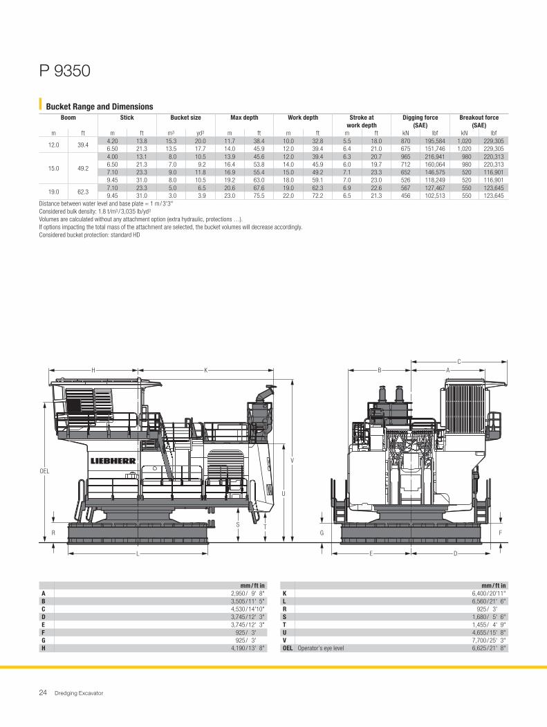
Bucket Range and DimensionsBoom Stick Bucket size Max depth Work depth Stroke at
work depthDigging force
(SAE)Breakout force
(SAE)m ft m ft m3 yd3 m ft m ft m ft kN lbf kN lbf
12.0 39.4 4.20 13.8 15.3 20.0 11.7 38.4 10.0 32.8 5.5 18.0 870 195,584 1,020 229,3056.50 21.3 13.5 17.7 14.0 45.9 12.0 39.4 6.4 21.0 675 151,746 1,020 229,305
15.0 49.2
4.00 13.1 8.0 10.5 13.9 45.6 12.0 39.4 6.3 20.7 965 216,941 980 220,3136.50 21.3 7.0 9.2 16.4 53.8 14.0 45.9 6.0 19.7 712 160,064 980 220,3137.10 23.3 9.0 11.8 16.9 55.4 15.0 49.2 7.1 23.3 652 146,575 520 116,9019.45 31.0 8.0 10.5 19.2 63.0 18.0 59.1 7.0 23.0 526 118,249 520 116,901
19.0 62.3 7.10 23.3 5.0 6.5 20.6 67.6 19.0 62.3 6.9 22.6 567 127,467 550 123,6459.45 31.0 3.0 3.9 23.0 75.5 22.0 72.2 6.5 21.3 456 102,513 550 123,645
Distance between water level and base plate = 1 m / 3'3"Considered bulk density: 1.8 t/m3 / 3,035 lb/yd3
Volumes are calculated without any attachment option (extra hydraulic, protections …).If options impacting the total mass of the attachment are selected, the bucket volumes will decrease accordingly.Considered bucket protection: standard HD
H
G
E D
B AC
F
L
R
OEL
S
R0126.02
T
U
V
K
P 9350
Dredging Excavator 25
H
G
E D
BA
C
F
L
R
OEL
S
R0125.02
T
U
V
K
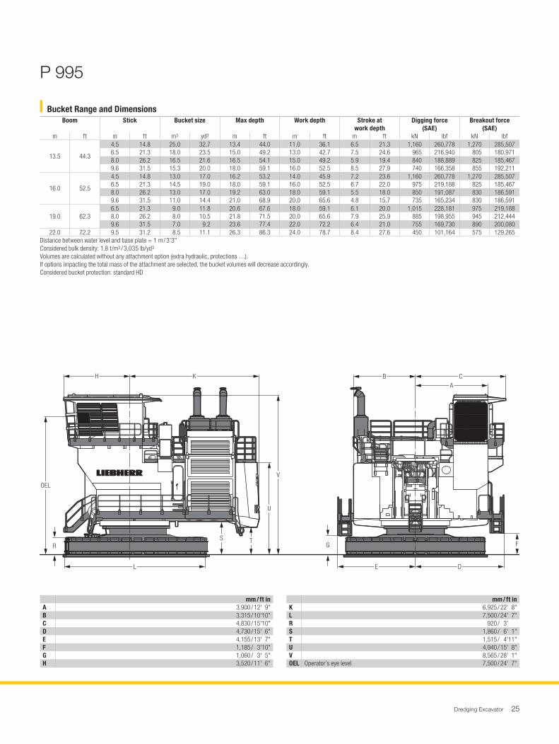
mm / ft inA 3,900 / 12' 9"B 3,315 / 10'10"C 4,830 / 15'10"D 4,730 / 15' 6"E 4,155 / 13' 7"F 1,185 / 3'10"G 1,060 / 3' 5"H 3,520 / 11' 6"
mm / ft inK 6,925 / 22' 8"L 7,500 / 24' 7"R 920 / 3' S 1,860 / 6' 1"T 1,515 / 4'11"U 4,940 / 15' 8"V 8,565 / 28' 1"OEL Operator’s eye level 7,500 / 24' 7"
Bucket Range and DimensionsBoom Stick Bucket size Max depth Work depth Stroke at
work depthDigging force
(SAE)Breakout force
(SAE)m ft m ft m3 yd3 m ft m ft m ft kN lbf kN lbf
13.5 44.3
4.5 14.8 25.0 32.7 13.4 44.0 11.0 36.1 6.5 21.3 1,160 260,778 1,270 285,5076.5 21.3 18.0 23.5 15.0 49.2 13.0 42.7 7.5 24.6 965 216,940 805 180,9718.0 26.2 16.5 21.6 16.5 54.1 15.0 49.2 5.9 19.4 840 188,889 825 185,4679.6 31.5 15.3 20.0 18.0 59.1 16.0 52.5 8.5 27.9 740 166,358 855 192,211
16.0 52.5
4.5 14.8 13.0 17.0 16.2 53.2 14.0 45.9 7.2 23.6 1,160 260,778 1,270 285,5076.5 21.3 14.5 19.0 18.0 59.1 16.0 52.5 6.7 22.0 975 219,188 825 185,4678.0 26.2 13.0 17.0 19.2 63.0 18.0 59.1 5.5 18.0 850 191,087 830 186,5919.6 31.5 11.0 14.4 21.0 68.9 20.0 65.6 4.8 15.7 735 165,234 830 186,591
19.0 62.36.5 21.3 9.0 11.8 20.6 67.6 18.0 59.1 6.1 20.0 1,015 228,181 975 219,1888.0 26.2 8.0 10.5 21.8 71.5 20.0 65.6 7.9 25.9 885 198,955 945 212,4449.6 31.5 7.0 9.2 23.6 77.4 22.0 72.2 6.4 21.0 755 169,730 890 200,080
22.0 72.2 9.5 31.2 8.5 11.1 26.3 86.3 24.0 78.7 8.4 27.6 450 101,164 575 129,265Distance between water level and base plate = 1 m / 3'3"Considered bulk density: 1.8 t/m3 / 3,035 lb/yd3
Volumes are calculated without any attachment option (extra hydraulic, protections …).If options impacting the total mass of the attachment are selected, the bucket volumes will decrease accordingly.Considered bucket protection: standard HD
P 995
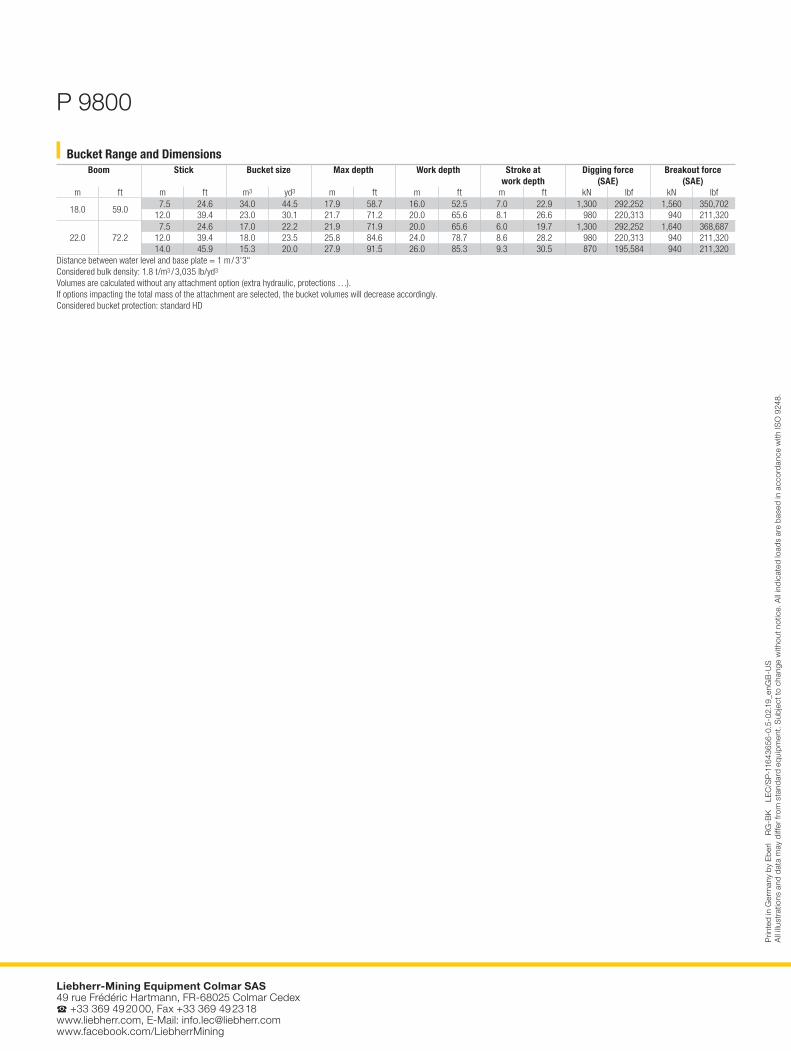
Bucket Range and DimensionsBoom Stick Bucket size Max depth Work depth Stroke at
work depthDigging force
(SAE)Breakout force
(SAE)m ft m ft m3 yd3 m ft m ft m ft kN lbf kN lbf
18.0 59.0 7.5 24.6 34.0 44.5 17.9 58.7 16.0 52.5 7.0 22.9 1,300 292,252 1,560 350,70212.0 39.4 23.0 30.1 21.7 71.2 20.0 65.6 8.1 26.6 980 220,313 940 211,320
22.0 72.2 7.5 24.6 17.0 22.2 21.9 71.9 20.0 65.6 6.0 19.7 1,300 292,252 1,640 368,68712.0 39.4 18.0 23.5 25.8 84.6 24.0 78.7 8.6 28.2 980 220,313 940 211,32014.0 45.9 15.3 20.0 27.9 91.5 26.0 85.3 9.3 30.5 870 195,584 940 211,320
Distance between water level and base plate = 1 m / 3'3"Considered bulk density: 1.8 t/m3 / 3,035 lb/yd3
Volumes are calculated without any attachment option (extra hydraulic, protections …).If options impacting the total mass of the attachment are selected, the bucket volumes will decrease accordingly.Considered bucket protection: standard HD
P 9800
Liebherr-Mining Equipment Colmar SAS 49 rue Frédéric Hartmann, FR-68025 Colmar CedexS +33 369 49 20 00, Fax +33 369 49 23 18www.liebherr.com, E-Mail: [email protected] www.facebook.com/LiebherrMining
Prin
ted
in G
erm
any
by E
berl
RG
-BK
LE
C/S
P-1
1643
656-
0.5-
02.1
9_en
GB
-US
A
ll ill
ustr
atio
ns a
nd d
ata
may
diff
er fr
om s
tand
ard
equi
pmen
t. S
ubje
ct to
cha
nge
with
out n
otic
e. A
ll in
dica
ted
load
s ar
e ba
sed
in a
ccor
danc
e w
ith IS
O 9
248.