Embed Size (px)
DESCRIPTION
Lecture Notes
Citation preview
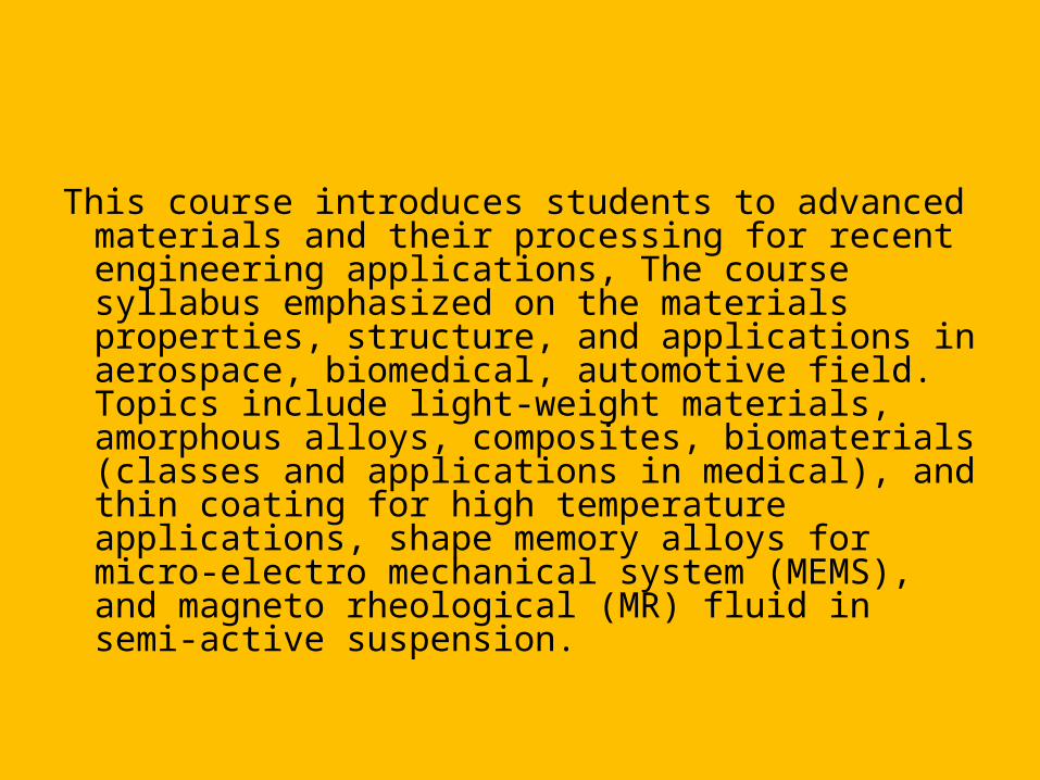
This course introduces students to advanced materials and their processing for recent engineering applications, The course syllabus emphasized on the materials properties, structure, and applications in aerospace, biomedical, automotive field. Topics include light-weight materials, amorphous alloys, composites, biomaterials (classes and applications in medical), and thin coating for high temperature applications, shape memory alloys for micro-electro mechanical system (MEMS), and magneto rheological (MR) fluid in semi-active suspension.
COURSE OUTCOME
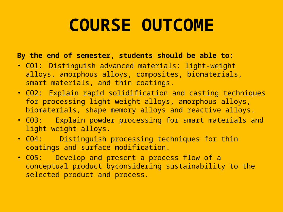
By the end of semester, students should be able to:• CO1: Distinguish advanced materials: light-weight alloys,
amorphous alloys, composites, biomaterials, smart materials, and thin coatings.
• CO2: Explain rapid solidification and casting techniques for processing light weight alloys, amorphous alloys, biomaterials, shape memory alloys and reactive alloys.
• CO3: Explain powder processing for smart materials and light weight alloys.
• CO4: Distinguish processing techniques for thin coatings and surface modification.
• CO5: Develop and present a process flow of a conceptual product byconsidering sustainability to the selected product and process.
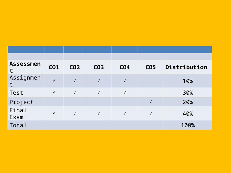
Assessment
CO1 CO2 CO3 CO4 CO5 Distribution
Assignment
√ √ √ √ 10%
Test √ √ √ √ 30%Project √ 20%Final Exam √ √ √ √ √ 40%Total 100%
Topic Contents
• Introduction.• Materials Science and Engineering• Classification of Materials• Explain definition and types of advanced
materials and brief history of engineering materials revolution.
• Explain significance of advanced materials for aerospace and biomedical applications, high thermal resistance. and sensor development.
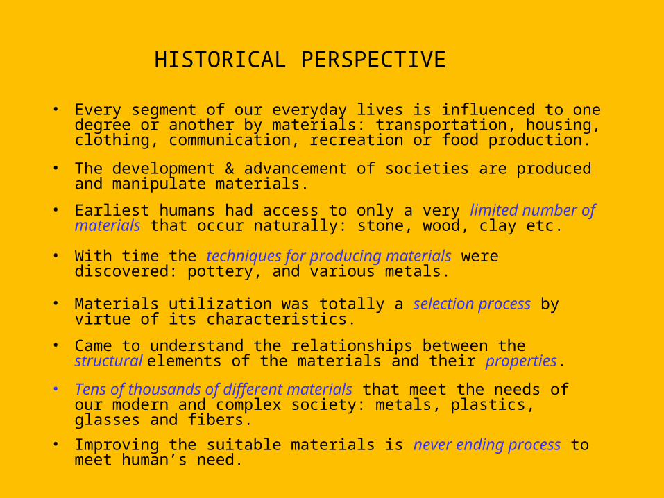
HISTORICAL PERSPECTIVE
• Every segment of our everyday lives is influenced to one degree or another by materials: transportation, housing, clothing, communication, recreation or food production.
• The development & advancement of societies are produced and manipulate materials.
• Earliest humans had access to only a very limited number of materials that occur naturally: stone, wood, clay etc.
• With time the techniques for producing materials were discovered: pottery, and various metals.
• Materials utilization was totally a selection process by virtue of its characteristics.
• Came to understand the relationships between the structural elements of the materials and their properties.
• Tens of thousands of different materials that meet the needs of our modern and complex society: metals, plastics, glasses and fibers.
• Improving the suitable materials is never ending process to meet human’s need.
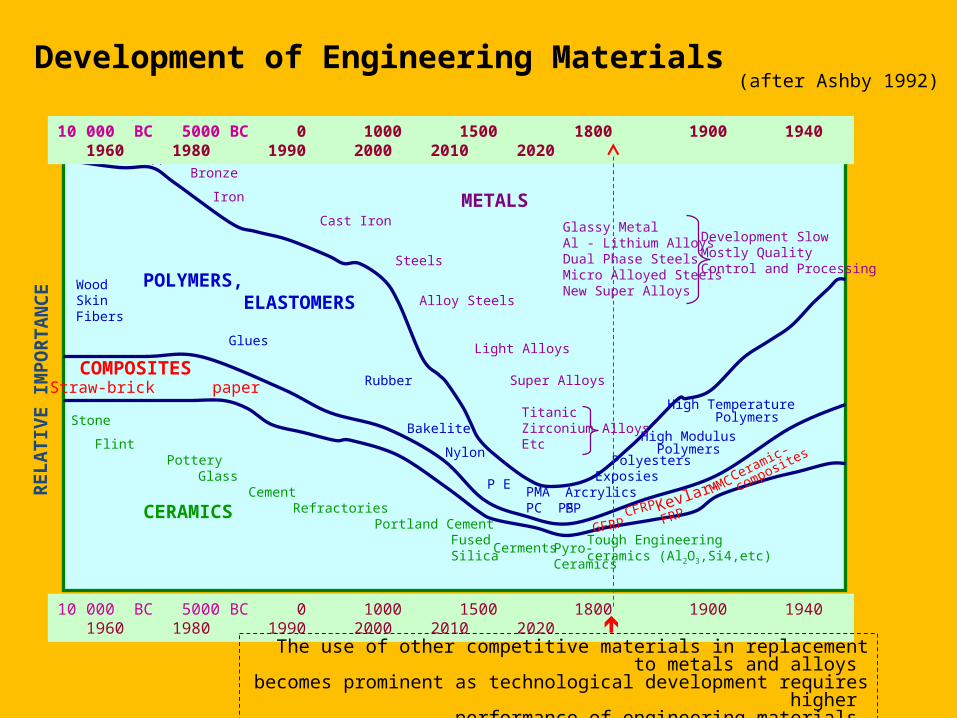
Development of Engineering Materials(after Ashby 1992)
RELA
TIVE
IMPO
RTAN
CE
DATE (Year)10 000 BC 5000 BC 0 1000 1500 1800 1900 1940 1960 1980 1990 2000 2010 2020
METALS
POLYMERS, ELASTOMERS
COMPOSITES
CERAMICS
Straw-brick paper
GFRPCFRPKevlar-
FRP
MMC
Gold CopperBronze
Iron
Cast Iron
Steels
Alloy Steels
Light Alloys
Super Alloys
TitanicZirconiumEtc
Alloys
Glassy MetalAl - Lithium AlloysDual Phase SteelsMicro Alloyed SteelsNew Super Alloys
Development SlowMostly QualityControl and Processing
WoodSkinFibers
Glues
Rubber
Bakelite
Nylon
P E PMAPC PS
ArcrylicsPP
ExposiesPolyesters
High Modulus Polymers
High Temperature PolymersStone
Flint Pottery
GlassCement
RefractoriesPortland Cement
FusedSilica Cerments Pyro-
Ceramics
Tough Engineeringceramics (Al2O3,Si4,etc)
10 000 BC 5000 BC 0 1000 1500 1800 1900 1940 1960 1980 1990 2000 2010 2020
Ceramic-
composites
The use of other competitive materials in replacement to metals and alloys becomes prominent as technological development requires higher
performance of engineering materials
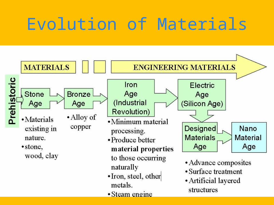
Evolution of Materials
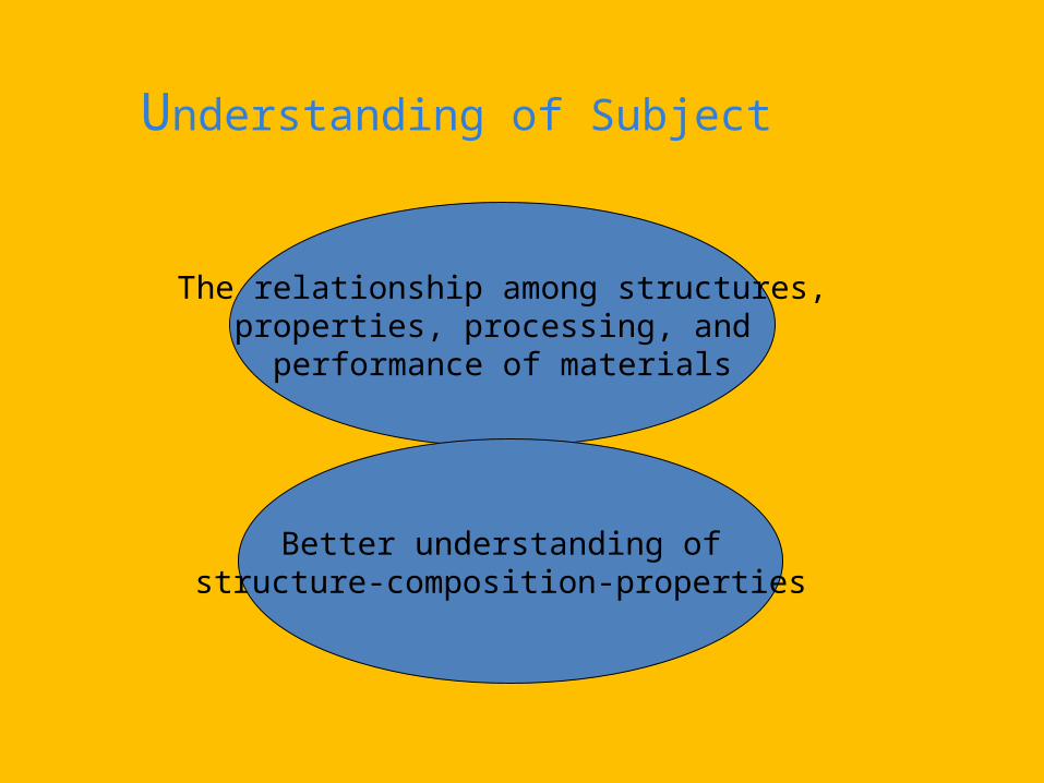
Understanding of Subject
The relationship among structures,properties, processing, and
performance of materials
Better understanding of structure-composition-properties
© 2003 B
rooks/Cole Publishing / T
homson L
earning™
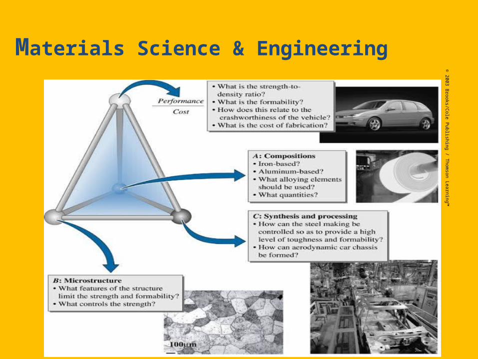
Materials Science & Engineering
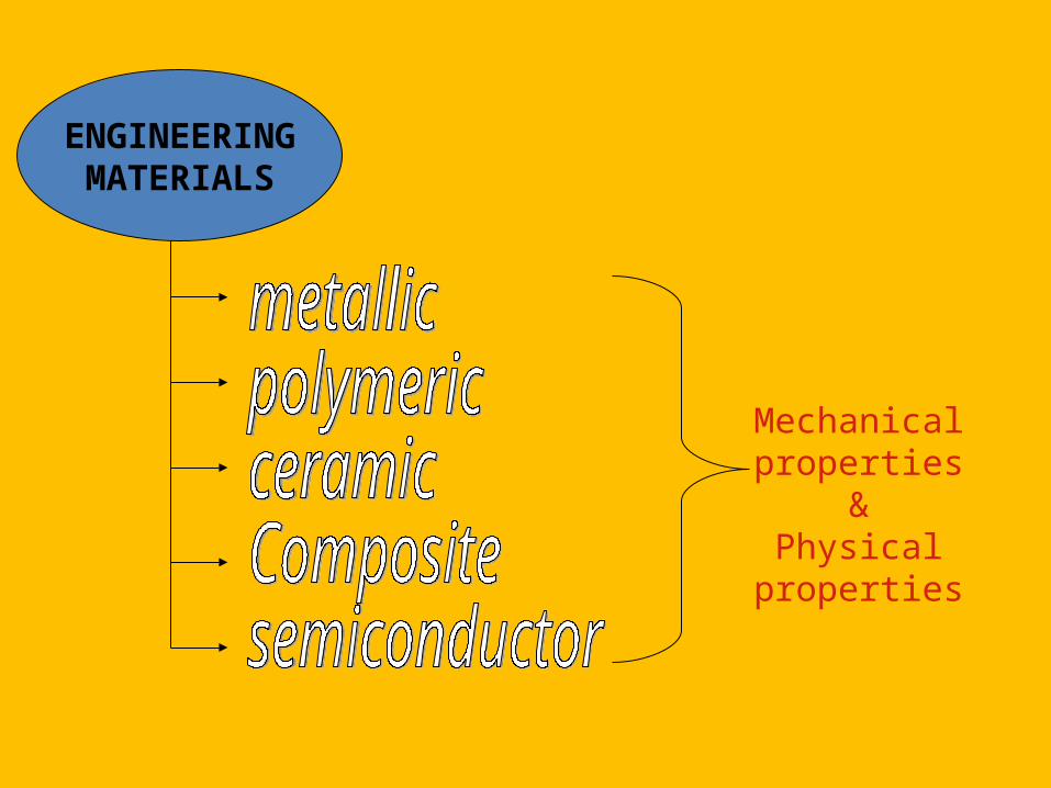
ENGINEERINGMATERIALS
Mechanical properties
&Physical
properties
Properties of Materials
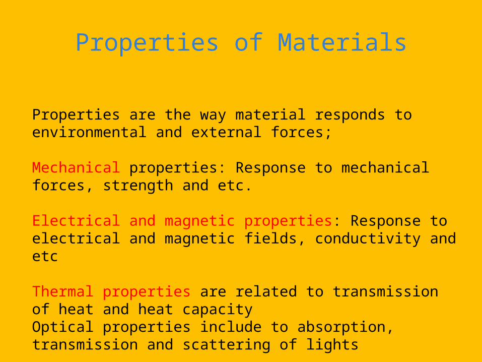
Properties are the way material responds to environmental and external forces;
Mechanical properties: Response to mechanical forces, strength and etc.
Electrical and magnetic properties: Response to electrical and magnetic fields, conductivity and etc
Thermal properties are related to transmission of heat and heat capacityOptical properties include to absorption, transmission and scattering of lights
Chemical stability in contact with environment – corrosion resistance
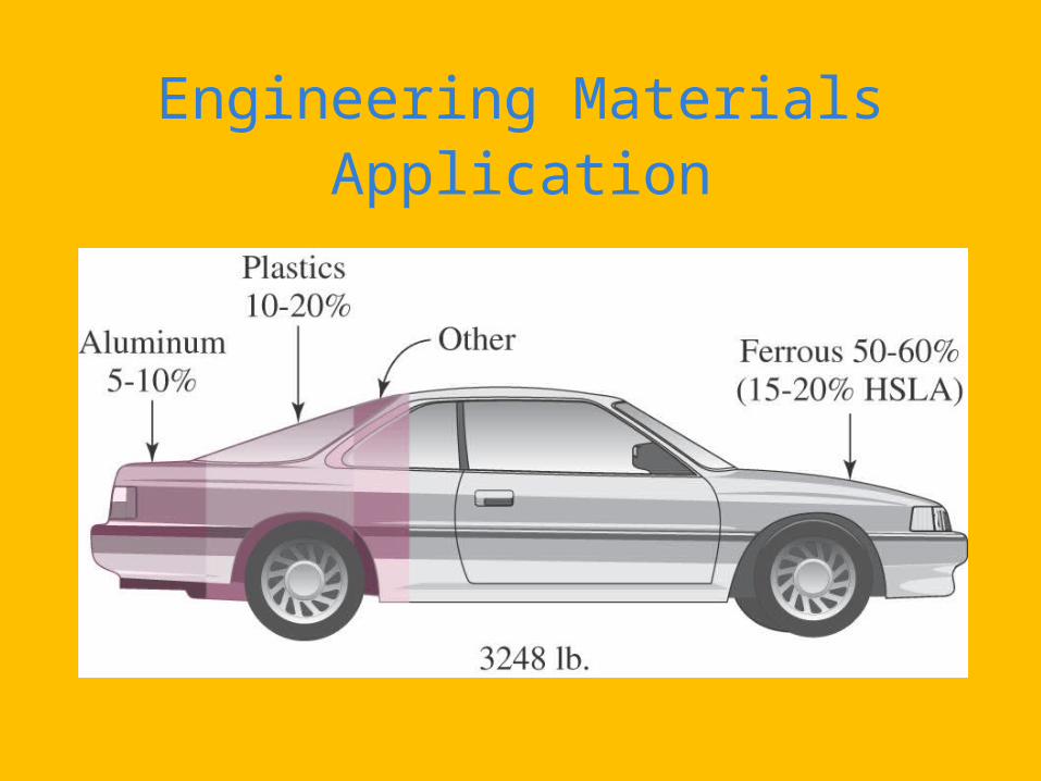
Engineering Materials Application
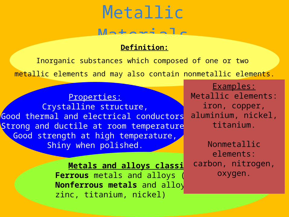
Metallic MaterialsDefinition:
Inorganic substances which composed of one or two
metallic elements and may also contain nonmetallic elements.
Properties:Crystalline structure,
Good thermal and electrical conductors,Strong and ductile at room temperature,
Good strength at high temperature,Shiny when polished.
Metals and alloys classification:Ferrous metals and alloys (steels, cast irons)Nonferrous metals and alloys (aluminium, copper, zinc, titanium, nickel)
Examples:Metallic elements:
iron, copper, aluminium, nickel, titanium.
Nonmetallic elements:carbon, nitrogen, oxygen.
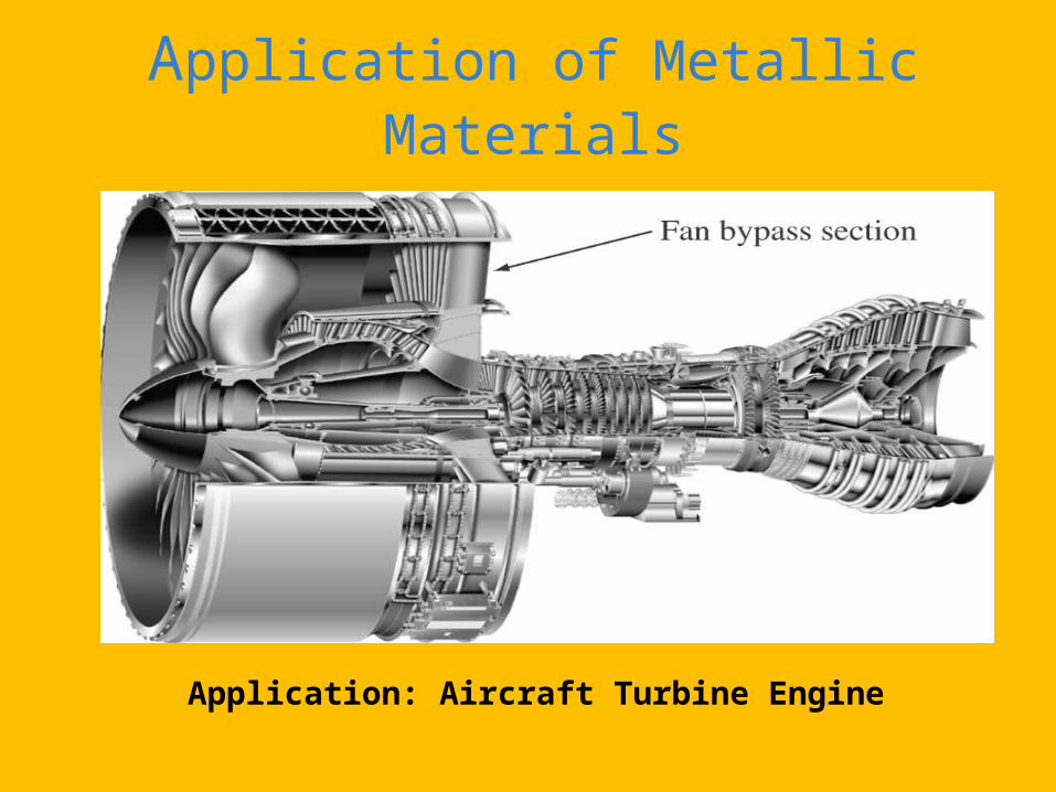
Application of Metallic Materials
Application: Aircraft Turbine Engine
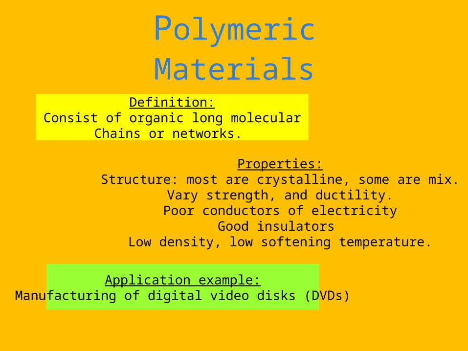
Polymeric Materials
Definition:Consist of organic long molecular
Chains or networks.
Properties:Structure: most are crystalline, some are mix.
Vary strength, and ductility.Poor conductors of electricity
Good insulators Low density, low softening temperature.
Application example:Manufacturing of digital video disks (DVDs)
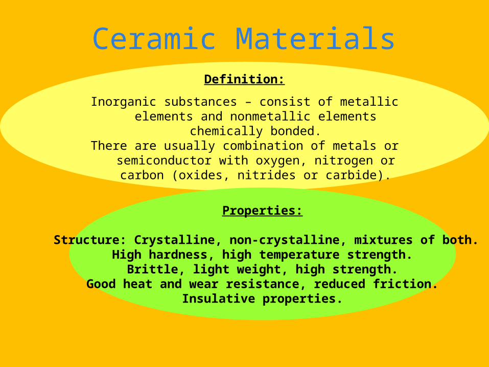
Ceramic Materials
Definition:
Inorganic substances – consist of metallic elements and nonmetallic elements chemically bonded.
There are usually combination of metals or semiconductor with oxygen, nitrogen or carbon (oxides, nitrides or carbide).
Properties:
Structure: Crystalline, non-crystalline, mixtures of both.High hardness, high temperature strength.
Brittle, light weight, high strength.Good heat and wear resistance, reduced friction.
Insulative properties.
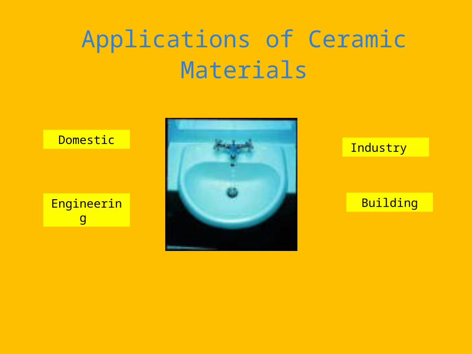
Applications of Ceramic Materials
Domestic
Engineering Building
Industry
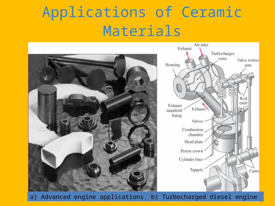
Applications of Ceramic Materials
a) Advanced engine applications. b) Turbocharged diesel engine
Composite Materials
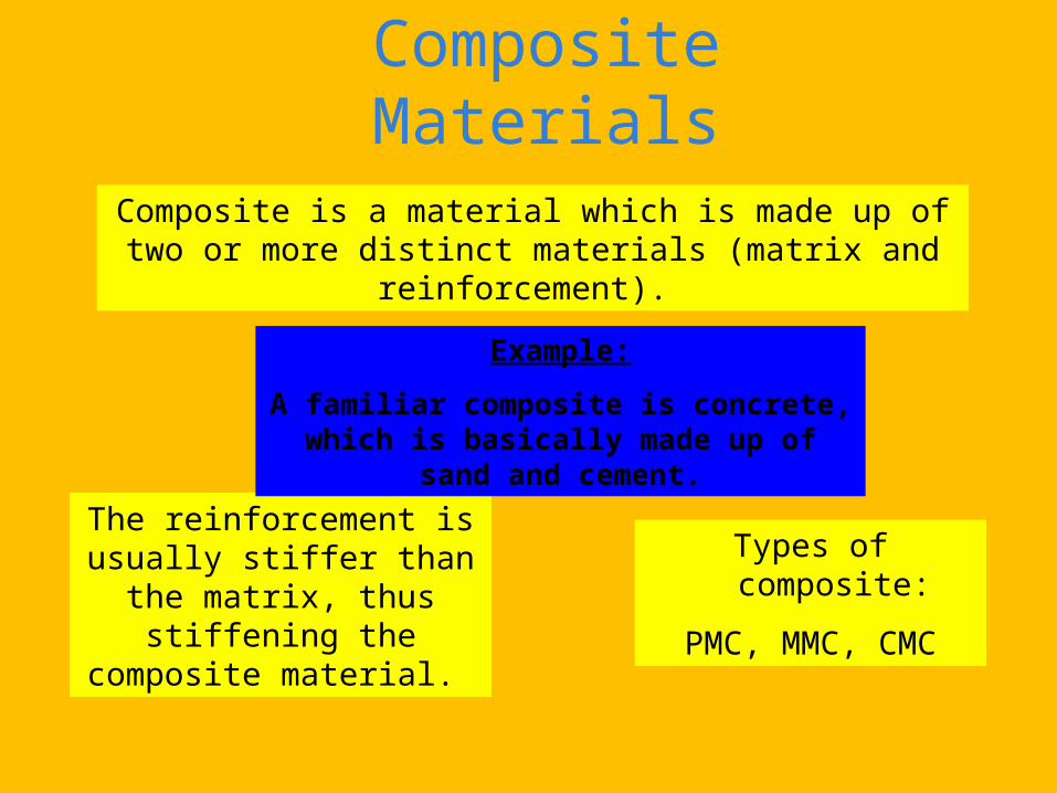
Composite is a material which is made up of two or more distinct materials (matrix and reinforcement).
Types of composite:
PMC, MMC, CMC
The reinforcement is usually stiffer than the matrix, thus
stiffening the composite material.
Example:
A familiar composite is concrete, which is basically made up of sand and cement.
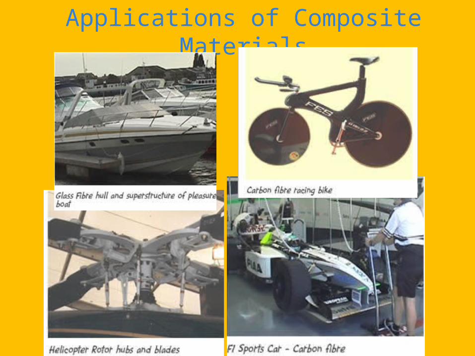
Applications of Composite Materials
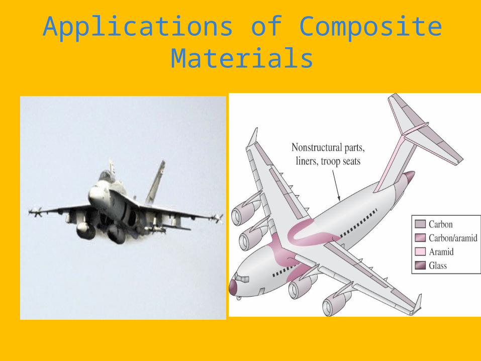
Applications of Composite Materials
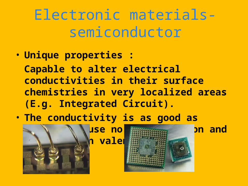
Electronic materials-semiconductor
• Unique properties : Capable to alter electrical conductivities in their surface chemistries in very localized areas (E.g. Integrated Circuit).
• The conductivity is as good as metals because no free electron and the electron valence is full.
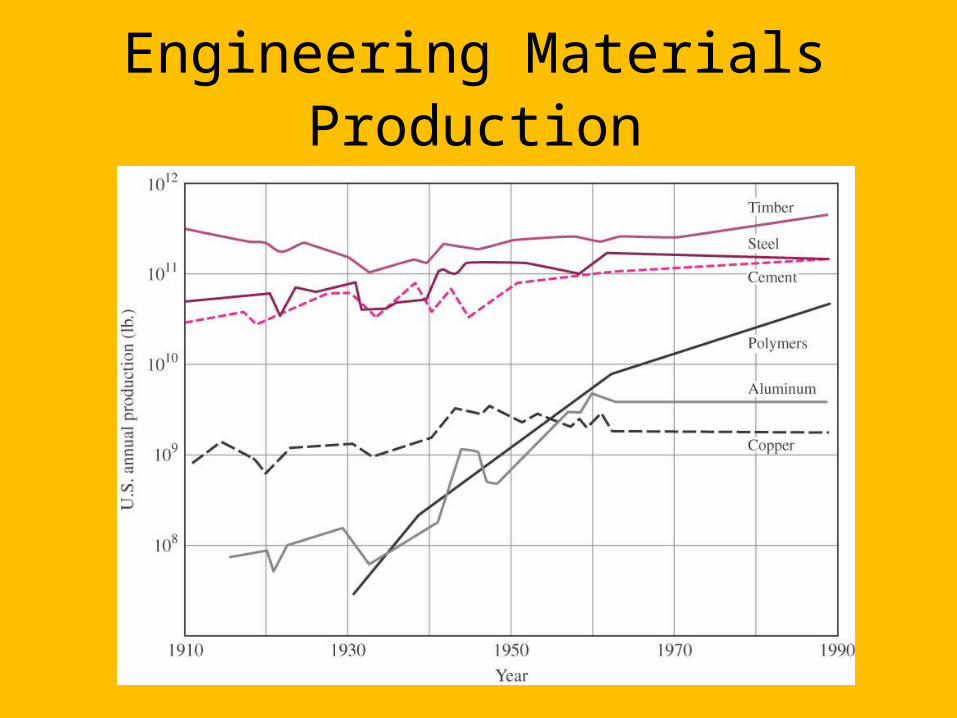
Engineering Materials Production

Engineering Materials Usage
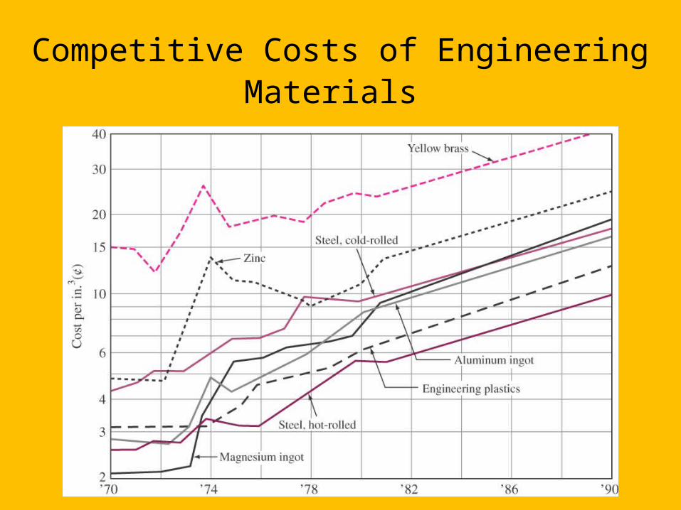
Competitive Costs of Engineering Materials
WHAT IS AN ADVANCED MATERIAL?
There are many different definitions of advanced materials and they have become so commonly used that most tend to assume that advanced materials are just materials. For a physical scientist considers that advanced materials could just as easily have been “Polymers”, for these are some of the most versatile advanced materials in use today and often are confused as plastics by many people.
WHAT IS AN ADVANCED MATERIAL?
Some scholars define advanced materials as those that involve knowledge (and creation of materials) at the molecular and/or atomic scale for the purpose of advancing technology and improving the human experience. These might be materials such as tiny carbon nanotubes that are being used in new types of X-ray tubes that are more efficient and safer than those now in use at airports and in doctor’s offices. These are also new coatings and methods of manufacturing of Teflon, which is an example of a polymer material made with chemical processing methods that causes much less pollution and is “environmentally friendly”. Other possibilities include materials used in new diagnostic methods such as those for medical biopsies.
WHAT IS AN ADVANCED MATERIAL?
Advanced materials research involves discoveries of fundamental principles of Chemistry, Mathematics and Physics that can be applied to control the molecular-level properties of new materials, and then fashioning materials and/or nanostructures for real-life applications. It involves knowing the conditions under which a material will be used and identifying candidate materials for this purpose.

WHAT IS AN ADVANCED MATERIAL?
There is always a real need for better materials and/or nanostructures - the issue is how much better and at what cost. An applied scientist, with a particular application in mind, will scour lists of known materials and/or nanostructures looking for one that meets his or her needs. If existing materials are unsuitable, the applied and basic scientist must work together to develop new materials and/or nanostructures. This synergism between what is available and what needs to be developed reflects the important and complementary roles of the basic and applied sciences in Materials Science. Neither one takes precedence over the other. Rather, they work hand-in-hand to fulfill our ever-growing need for new materials.
ADVANCED MATERIALS:
• Materials that are utilized in high-technology application• High-tech, a device or product that operates or functions using
relatively intricate and sophisticated principles• Electronic equipment, computers, fiber optic systems, spacecraft,
aircraft, and military rocketry.• They might be of all material types whose properties have been
enhanced or newly developed
Materials of the Future
A. SMART MATERIALS
A group of new and state of the art materials now being developed that will have a significant influence on many technologies.
Smart implies the ability to sense charges in environments and then respond to the changes in predetermined manners-traits that are also found in living organisms.
Component of smart materials (or system):• Some type of sensor (detect an input signal)• An actuator (perform a responsive and adaptive function)
Materials of the Future
B. NANOTECHNOLOGY
To understand the chemistry and physics of materials by studying large and complex structures to investigate the fundamental building blocks of these structures that are smaller and simpler. “Top-down” sciences
By SPM (scanning probe microscopes) permits to observe the individual atoms and molecules, and it has become possible to manipulate and move atoms and molecules to form new structures, thus, design new materials that are built from simple atomic level constituents (i.e. “materials by design”)
It enables to carefully arrange atoms to develop mechanical, electrical, magnetic, and other properties. “Bottom-up” sciences called nanotechnology.
Nano = 10-9, nanotechnology < 100 nm equivalent 500 atom diameters
Modern Materials Needs
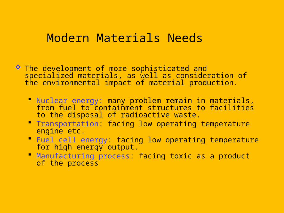
The development of more sophisticated and specialized materials, as well as consideration of the environmental impact of material production.
Nuclear energy: many problem remain in materials, from fuel to containment structures to facilities to the disposal of radioactive waste.
Transportation: facing low operating temperature engine etc. Fuel cell energy: facing low operating temperature for high energy
output. Manufacturing process: facing toxic as a product of the process
Modern Materials Needs
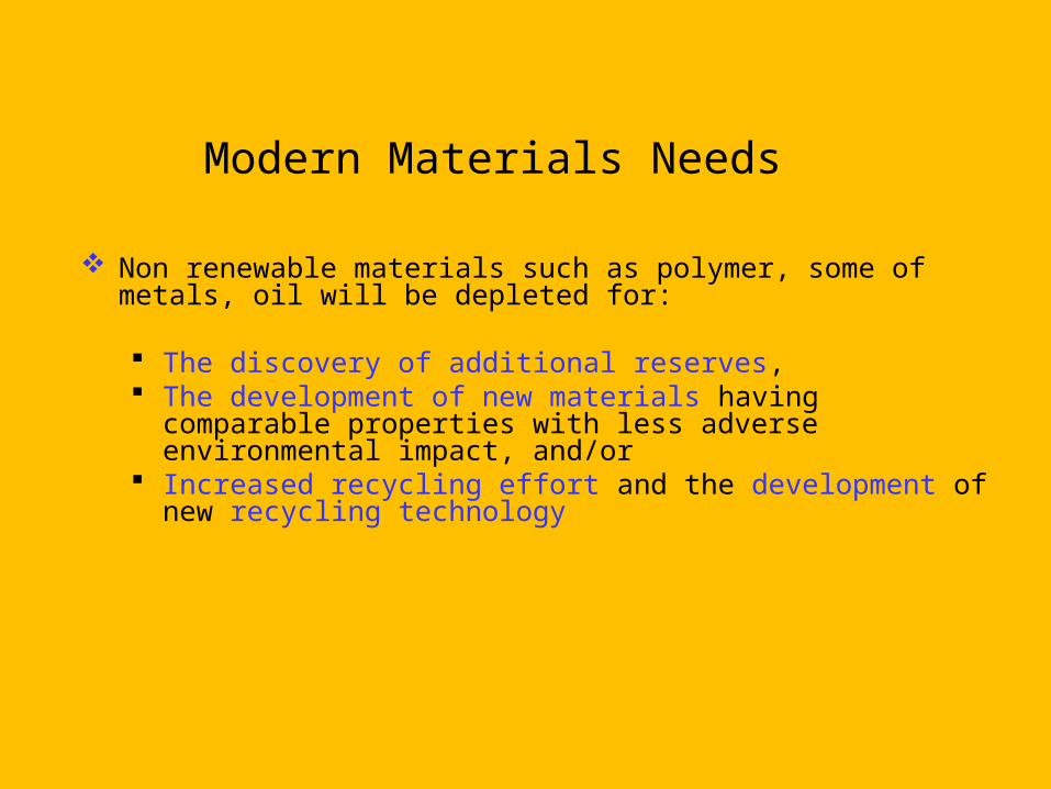
Non renewable materials such as polymer, some of metals, oil will be depleted for:
The discovery of additional reserves, The development of new materials having comparable properties
with less adverse environmental impact, and/or Increased recycling effort and the development of new recycling
technology
36
The Materials Selection Process
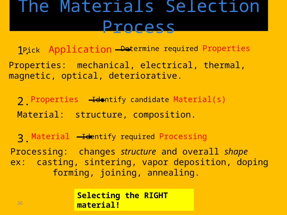
1. Pick Application Determine required Properties
Processing: changes structure and overall shapeex: casting, sintering, vapor deposition, doping forming, joining, annealing.
Properties: mechanical, electrical, thermal,magnetic, optical, deteriorative.
Material: structure, composition.2. Properties Identify candidate Material(s)
3. Material Identify required Processing
Selecting the RIGHT material!
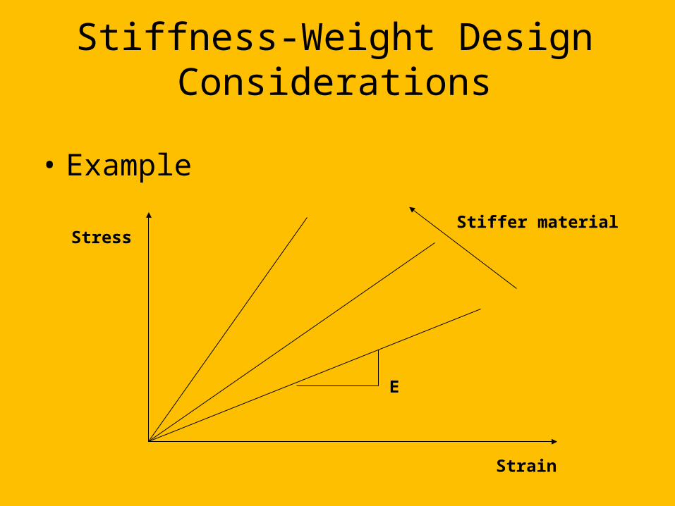
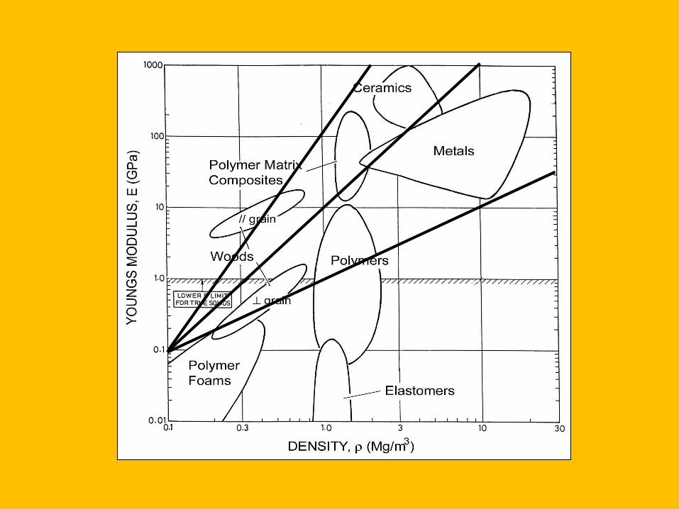
Stiffness-Weight Design Considerations
• Example
Strain
Stress
E
Stiffer material
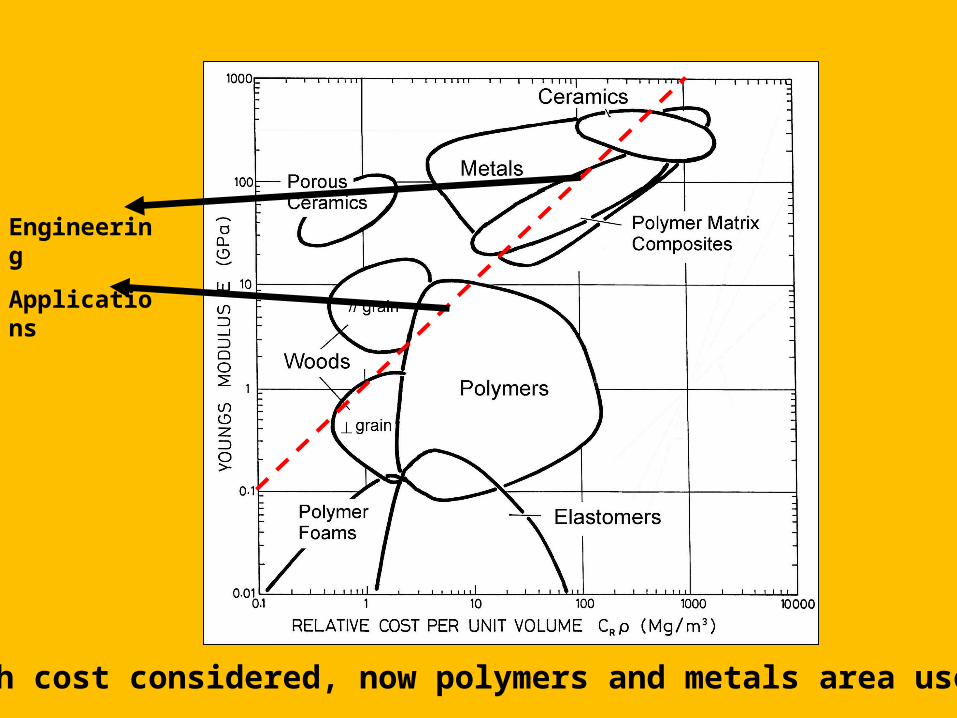
With cost considered, now polymers and metals area useful!
Engineering
Applications
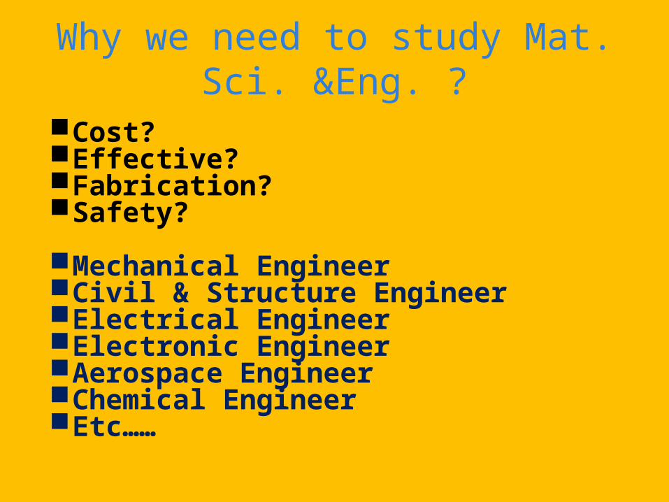
Why we need to study Mat. Sci. &Eng. ?
Cost?Effective?Fabrication?Safety?
Mechanical EngineerCivil & Structure EngineerElectrical EngineerElectronic EngineerAerospace EngineerChemical EngineerEtc……
U. Thomann 21:3715 41
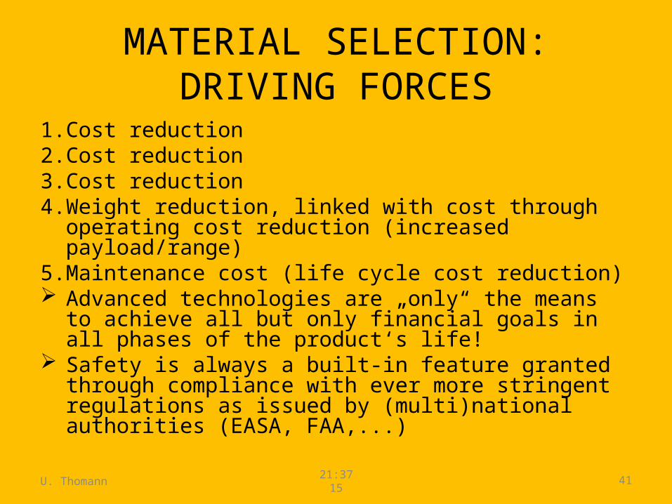
MATERIAL SELECTION: DRIVING FORCES
1. Cost reduction2. Cost reduction3. Cost reduction4. Weight reduction, linked with cost through operating cost
reduction (increased payload/range)5. Maintenance cost (life cycle cost reduction) Advanced technologies are „only“ the means to achieve all
but only financial goals in all phases of the product‘s life! Safety is always a built-in feature granted through
compliance with ever more stringent regulations as issued by (multi)national authorities (EASA, FAA,...)
U. Thomann 21:3715 42
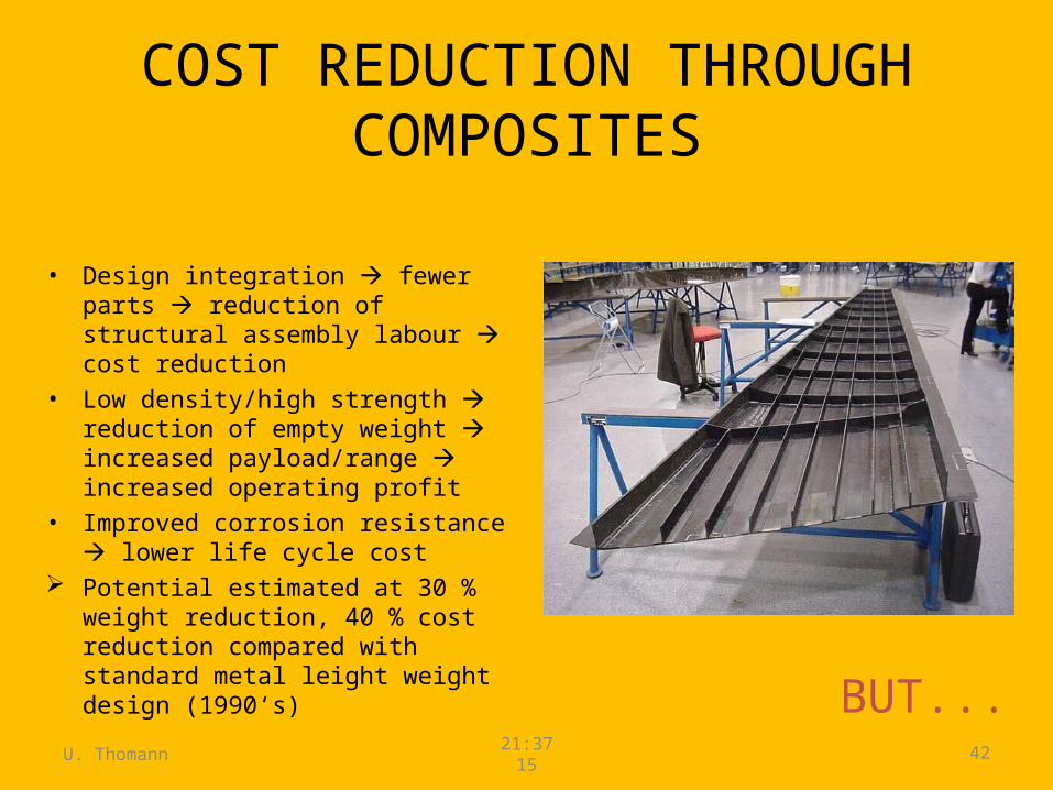
COST REDUCTION THROUGH COMPOSITES
• Design integration fewer parts reduction of structural assembly labour cost reduction
• Low density/high strength reduction of empty weight increased payload/range increased operating profit
• Improved corrosion resistance lower life cycle cost
Potential estimated at 30 % weight reduction, 40 % cost reduction compared with standard metal leight weight design (1990‘s) BUT...
U. Thomann 21:3715 43
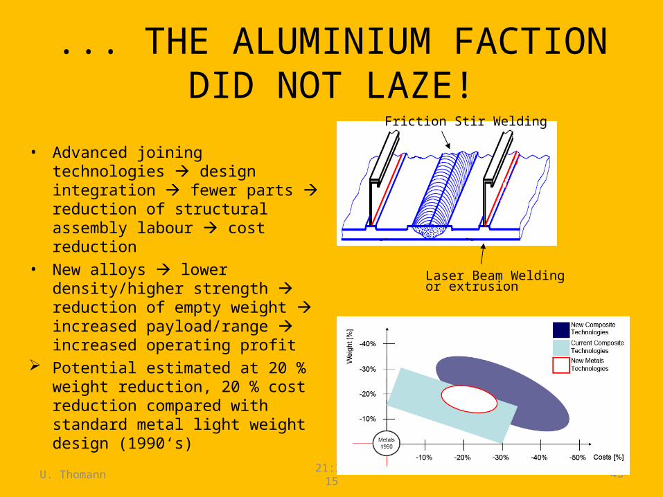
... THE ALUMINIUM FACTION DID NOT LAZE!
• Advanced joining technologies design integration fewer parts reduction of structural assembly labour cost reduction
• New alloys lower density/higher strength reduction of empty weight increased payload/range increased operating profit
Potential estimated at 20 % weight reduction, 20 % cost reduction compared with standard metal light weight design (1990‘s)
Friction Stir Welding
Laser Beam Weldingor extrusion
U. Thomann 21:3715 44
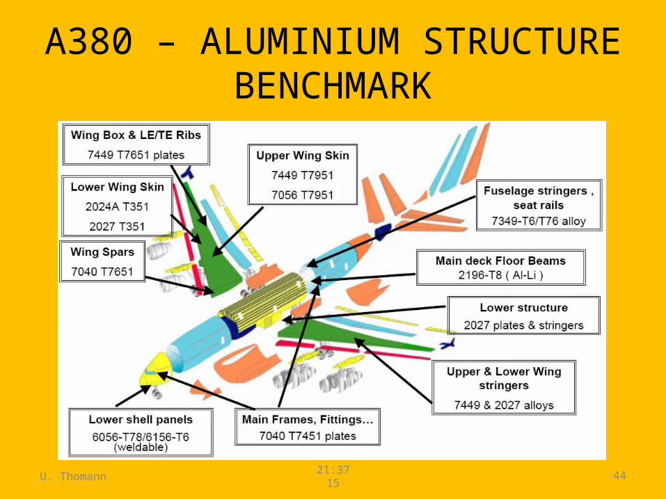
A380 – ALUMINIUM STRUCTURE BENCHMARK

U. Thomann 21:3715 45
AIRFRAME MATERIALS: PAST, PRESENT, FUTURE
Com
posi
te w
eigh
t pe
rcen
tage
Tendency:• More composite materials• Tailored matieral mix to improve over all systems performance

EXAMPLES OF MATERIAL SELECTIONS (OR REFUSALS)
INTERNAL REFERENCE: MP-00-MI-10-061, ISSUE 1

U. Thomann 21:3715 47
EFFICIENCY IMPROVEMENT THROUGH ADVANCED MATERIAL TECHNOLOGIES
• Higher combustion temperatures yield higher thermodynamic efficiency and thus lower fuel consumption
• Today‘s technology with single crystal nickel alloys and oxide dispersioned strengthened (ODS) super alloys with bleed air cooling cannot provide the required step change in fuel consumption
„New“ high temperature/high strength materials along with new design concepts required Ceramic matrix composites
max
ambientmax
T
TT
U. Thomann 21:3715 48
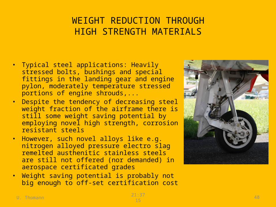
WEIGHT REDUCTION THROUGHHIGH STRENGTH MATERIALS
• Typical steel applications: Heavily stressed bolts, bushings and special fittings in the landing gear and engine pylon, moderately temperature stressed portions of engine shrouds,...
• Despite the tendency of decreasing steel weight fraction of the airframe there is still some weight saving potential by employing novel high strength, corrosion resistant steels
• However, such novel alloys like e.g. nitrogen alloyed pressure electro slag remelted austhenitic stainless steels are still not offered (nor demanded) in aerospace certificated grades
• Weight saving potential is probably not big enough to off-set certification cost
U. Thomann 21:3715 49
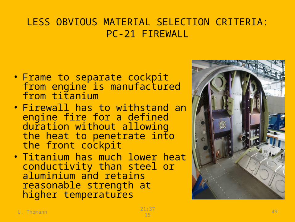
LESS OBVIOUS MATERIAL SELECTION CRITERIA:PC-21 FIREWALL
• Frame to separate cockpit from engine is manufactured from titanium
• Firewall has to withstand an engine fire for a defined duration without allowing the heat to penetrate into the front cockpit
• Titanium has much lower heat conductivity than steel or aluminium and retains reasonable strength at higher temperatures
U. Thomann 21:3715 50
ELASTOMERS
• Still the best material to cope with excessive wear experienced by the tires is natural rubber!
• O-ring seals and flexible hoses: make sure to select the right material depending on media to be sealed against or flowing through:– Chloroprene withstands fuel but not ozone and UV light– Isoprene is easy with ozone und UV light but not with fuel or hydraulic fluids– Nitrile butadiene rubber (NBR) happily swims in hydraulic fluids but should not be
exposed to ambient air with ozone and UV light– Fluoropolymer rubbers are expensive but cope with almost every environment,
even at somewhat elevated temperatures
U. Thomann 21:3715 51
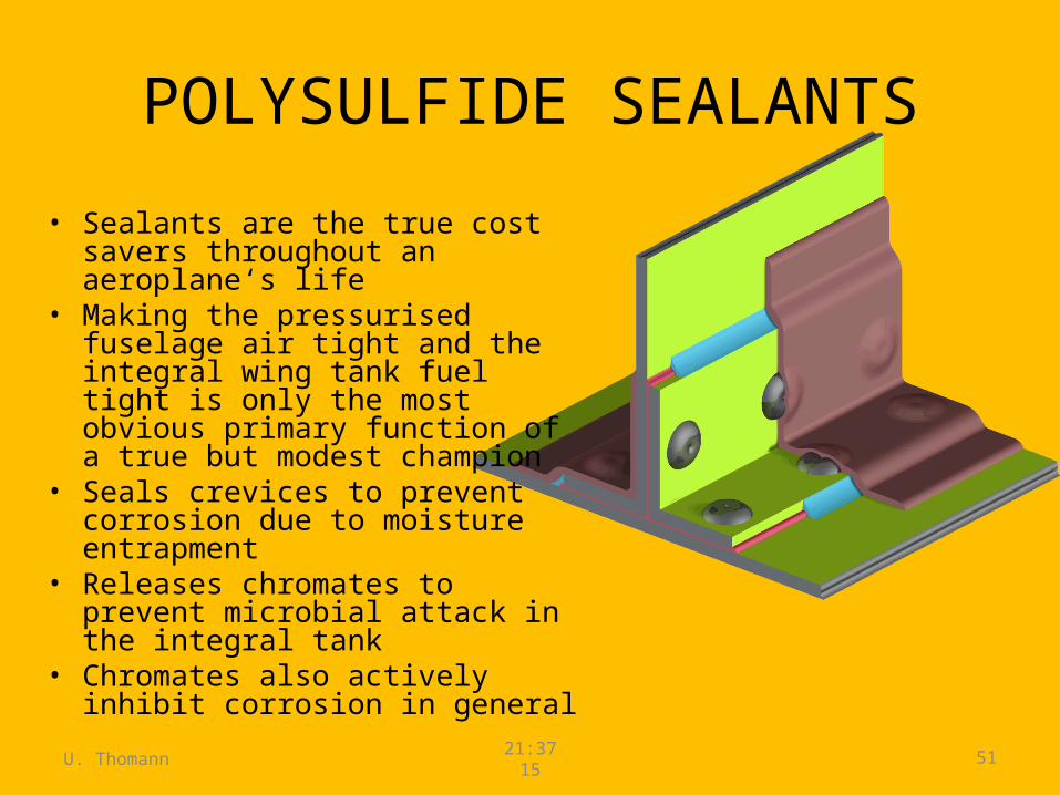
POLYSULFIDE SEALANTS
• Sealants are the true cost savers throughout an aeroplane‘s life
• Making the pressurised fuselage air tight and the integral wing tank fuel tight is only the most obvious primary function of a true but modest champion
• Seals crevices to prevent corrosion due to moisture entrapment
• Releases chromates to prevent microbial attack in the integral tank
• Chromates also actively inhibit corrosion in general
U. Thomann 21:3715 52
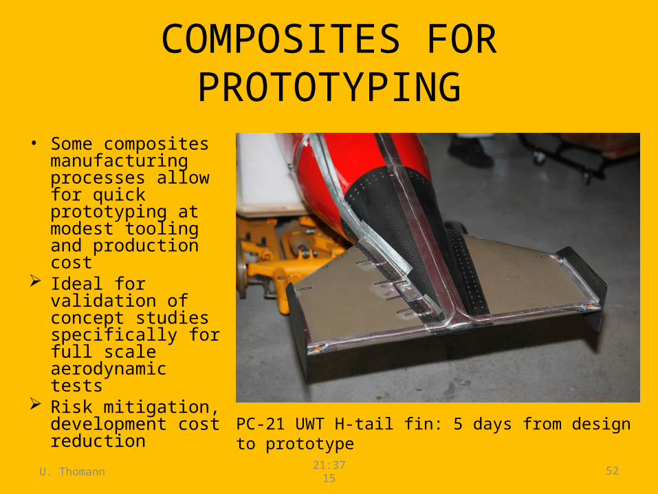
COMPOSITES FOR PROTOTYPING
• Some composites manufacturing processes allow for quick prototyping at modest tooling and production cost
Ideal for validation of concept studies specifically for full scale aerodynamic tests
Risk mitigation, development cost reduction
PC-21 UWT H-tail fin: 5 days from design to prototype

A SPOTLIGHT ON COMPOSITES:BENEFITS AND CHALLENGES
INTERNAL REFERENCE: MP-00-MI-10-061, ISSUE 1
U. Thomann21:3715 54
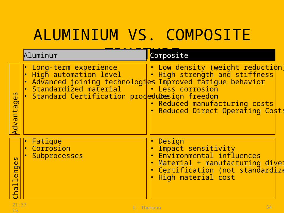
ALUMINIUM VS. COMPOSITE TRUCTURE
Adva
ntag
es
Aluminum
Chal
leng
es
Composite
• Long-term experience• High automation level• Advanced joining technologies• Standardized material • Standard Certification procedure
• Low density (weight reduction)• High strength and stiffness • Improved fatigue behavior• Less corrosion• Design freedom• Reduced manufacturing costs• Reduced Direct Operating Costs
• Fatigue• Corrosion • Subprocesses
• Design• Impact sensitivity• Environmental influences• Material + manufacturing diversity• Certification (not standardized mat.)• High material cost
U. Thomann 21:3715 55
IMPROVED CORROSION RESISTANCE – ONLY HALF OF THE TRUTH!
• Yes, by and large carbon fibre composites are pretty much unaffected by corrosive environments, but...
• ... aluminium alloys are even more affected when in direct contact with carbon fibres due to extreme electrochemical potential difference between carbon and aluminium
Cadmium plated stainless steel/nickel fasteners needed: More expensive heavier than aluminium fasteners
More titanium in direct contact with carbon fibre composites employed: More expensive raw material and more complex production processes than
aluminium Similar specific strength/stiffness as aluminium
U. Thomann 21:3715 56
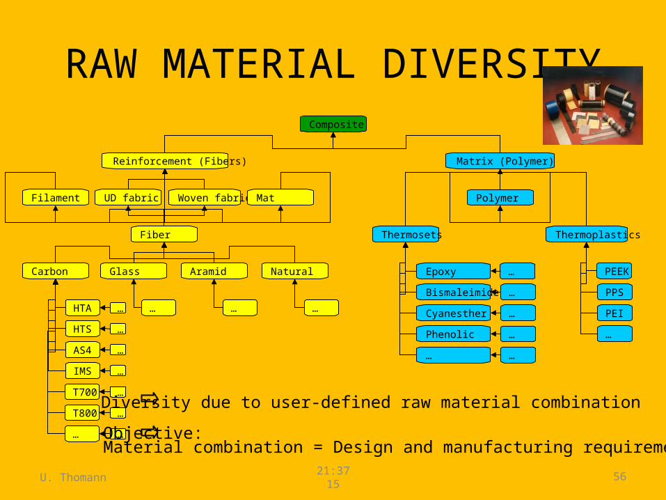
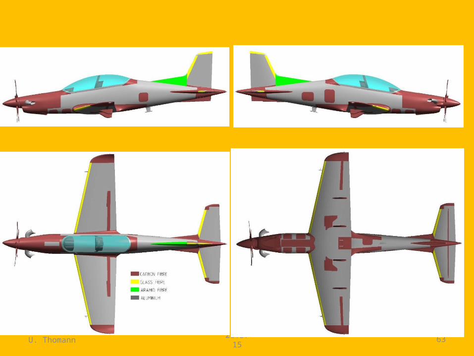
RAW MATERIAL DIVERSITYComposite
Reinforcement (Fibers)
Fiber
Carbon
Thermosets
Polymer
Matrix (Polymer)
Glass Aramid
Thermoplastics
Cyanesther
Epoxy
Bismaleimide
Phenolic
…
…
IMS
AS4
HTA
T800
UD fabric Woven fabric Mat
Natural
Filament
…
PPS
PEI
PEEK
HTS
T700
… … ……
…
…
…
…
…
…
…
…
…
…
…
Diversity due to user-defined raw material combination
Objective:Material combination = Design and manufacturing requirements
U. Thomann 21:3715 57
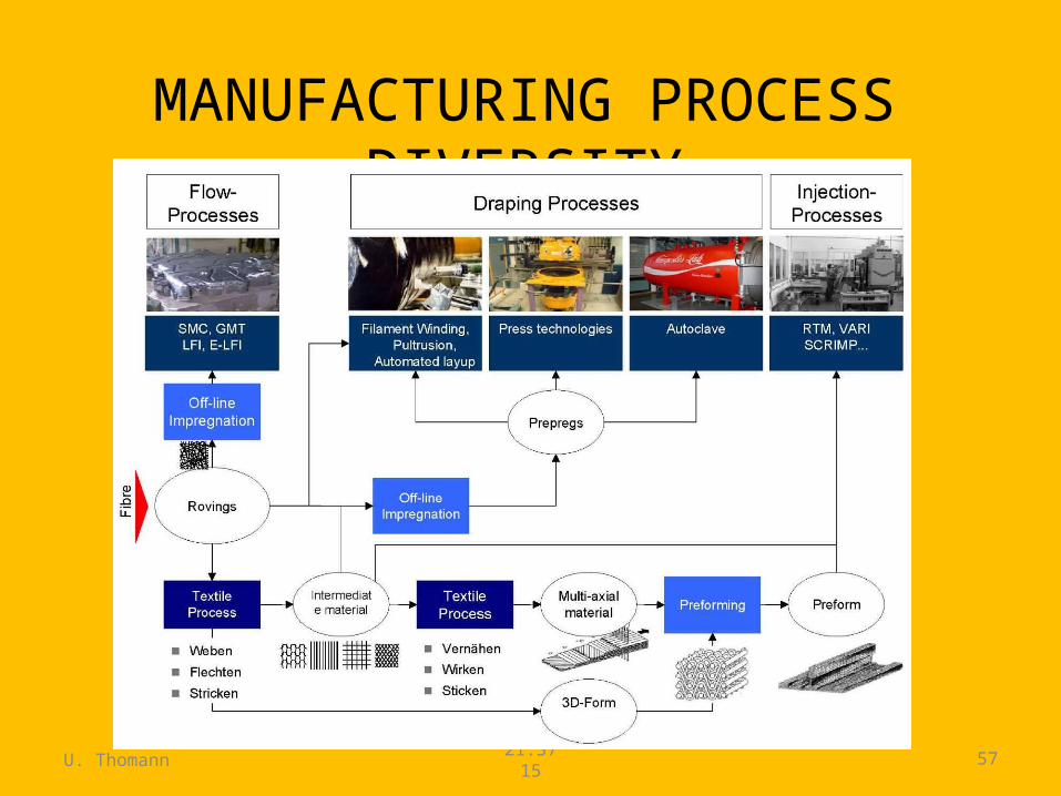
MANUFACTURING PROCESS DIVERSITY
U. Thomann 21:3715 58
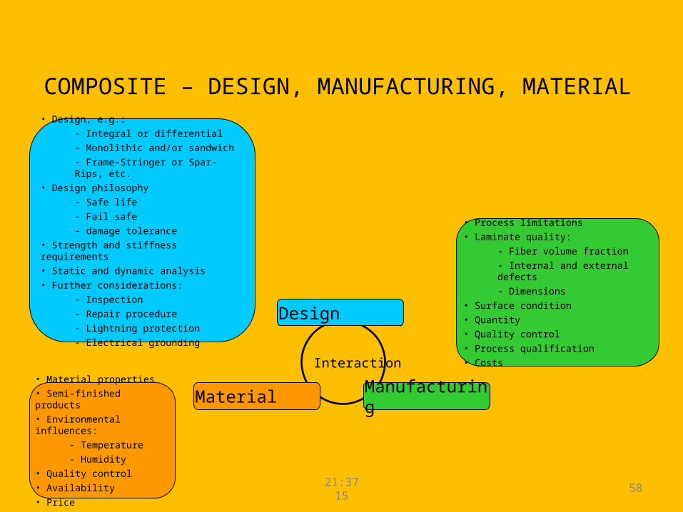
COMPOSITE – DESIGN, MANUFACTURING, MATERIAL
Interaction
Manufacturing
Design
Material
• Process limitations• Laminate quality:
- Fiber volume fraction- Internal and external defects- Dimensions
• Surface condition• Quantity• Quality control• Process qualification• Costs
• Design, e.g.:- Integral or differential- Monolithic and/or sandwich- Frame-Stringer or Spar-Rips, etc.
• Design philosophy- Safe life- Fail safe- damage tolerance
• Strength and stiffness requirements• Static and dynamic analysis• Further considerations:
- Inspection- Repair procedure - Lightning protection- Electrical grounding
• Material properties• Semi-finished products• Environmental influences:
- Temperature- Humidity
• Quality control• Availability• Price
U. Thomann 21:3715 59
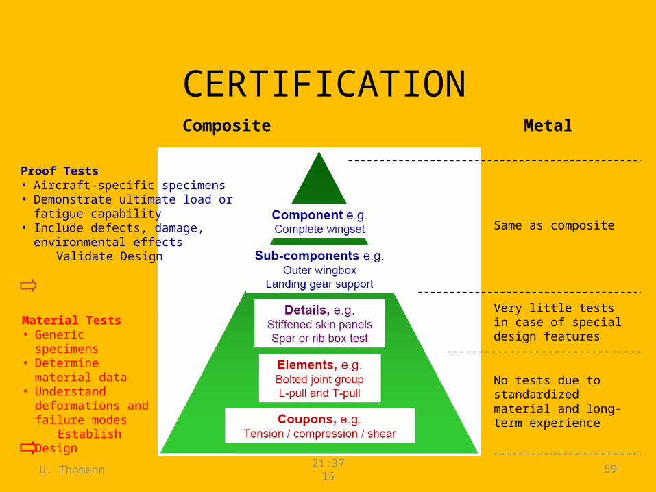
CERTIFICATIONComposite Metal
Material Tests• Generic specimens• Determine material
data• Understand
deformations and failure modes
Establish Design
Proof Tests• Aircraft-specific specimens• Demonstrate ultimate load or fatigue
capability• Include defects, damage, environmental
effects Validate Design
No tests due to standardized material and long-term experience
Very little tests in case of special design features
Same as composite
U. Thomann 21:3715 60
CERTIFICATION
E.g. coupons tests:• Mechanical properties, e.g.:
– Laminate: Strength and stiffness etc. in tension, compression and shear.– Engineering data: Strength in tension and compression with and without holes; bearing
strength; Compression After Impact strength• Physical properties, e.g.:
– Density, glass transition temperature Tg, volume fraction, cured ply thickness• Environmental influences, e.g.:
– From -55°C to +55°C OAT in dry and wet conditions– Contaminations (hydraulic fluid, jet fuel, solvents, paint stripper)
• Requirements for storage, handling, processing, machining etc. Data must be established by means of a qualification programme for each specific composite
material.

U. Thomann 21:3715 61
• Raw material testing– Physical and chemical tests– Mechanical coupons tests
• Manufacturing control– Process control
• Component testing– Visual inspection– Dimension and weight control– Ultrasonic inspection– Mechanical test of coupons which accompanied the curing process
QUALITY CONTROL
U. Thomann 21:3715 62
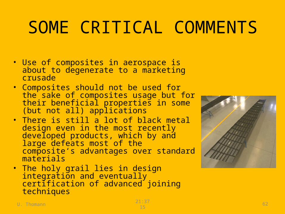
SOME CRITICAL COMMENTS
• Use of composites in aerospace is about to degenerate to a marketing crusade
• Composites should not be used for the sake of composites usage but for their beneficial properties in some (but not all) applications
• There is still a lot of black metal design even in the most recently developed products, which by and large defeats most of the composite‘s advantages over standard materials
• The holy grail lies in design integration and eventually certification of advanced joining techniques
U. Thomann 21:3715 63
U. Thomann 21:3715 64
SUMMARY• Deep knowledge of the present state of the art in each
class of materials is essential• There is no right or wrong material selection; it is
rather a complex decision making process depending on– OEM’s design and manufacturing skill and experience level– Requirements– Balance of value and cost
• Mastering the art of selecting the best performing material for any given purpose of application is really at the core of the successful design of an aerospace vehicle

Advanced Machining Processes
Chemical MillingPhotochemical BlankingElectrochemical MachiningPulsed Electrochemical MachiningElectrochemical GrindingElectrical-Discharge MachiningElectrical-Discharge GrindingElectrical-Discharge Wire CuttingLaser-Beam MachiningElectron Beam MachiningPlasma Arc CuttingWater Jet MachiningAbrasive Water Jet MachiningAbrasive Jet Machining
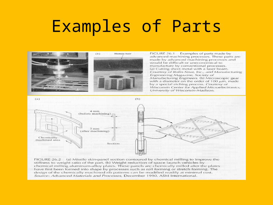
Examples of Parts
Chemical Milling
Produces shallow cavities on a workpiece, usually to reduce weight
The area affected by the chemical reagent is controlled by masking or by partial immersion
Chemical Milling
Chemical Milling
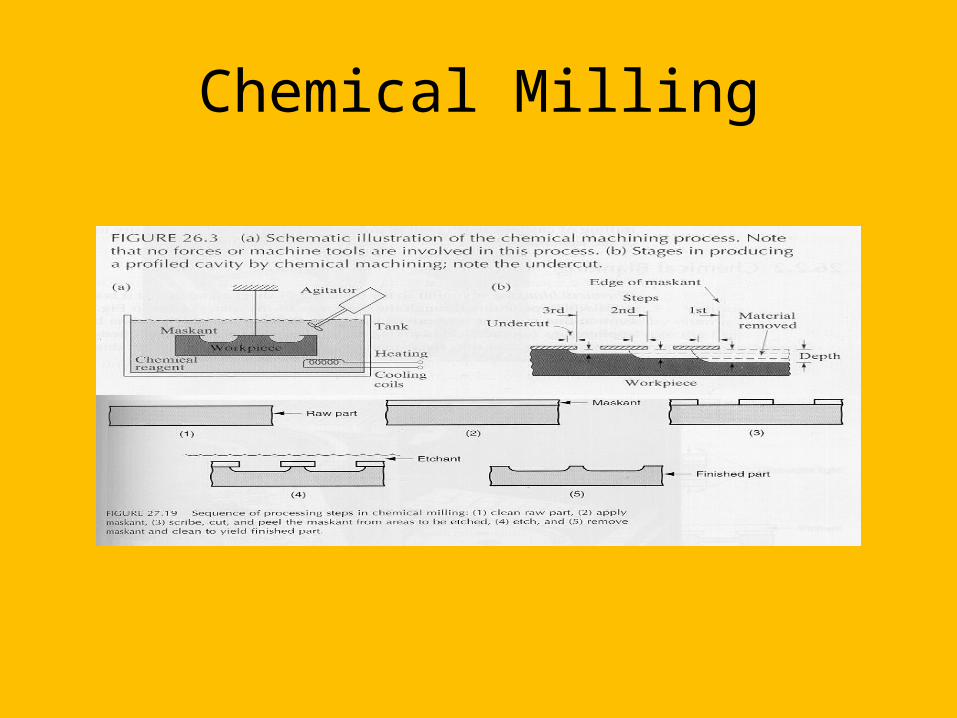
Procedure:1. Relieve residual stresses to prevent warping2. Clean the material surface3. Apply masking material4. Remove the masking on regions that require etching5. Apply the reagents6. Wash the part7. Remove remaining masking8. Additional finishing or chemical milling procedures
may be used
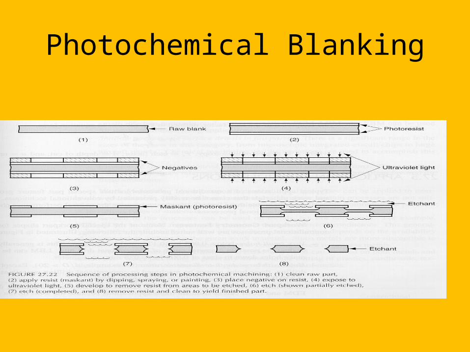
Photochemical Blanking
Uses chemicals and photographic processes to remove material, usually from a thin sheet
Can produce complex shapes on metals as thin as .0025 mm without forming burrs
Photochemical Blanking
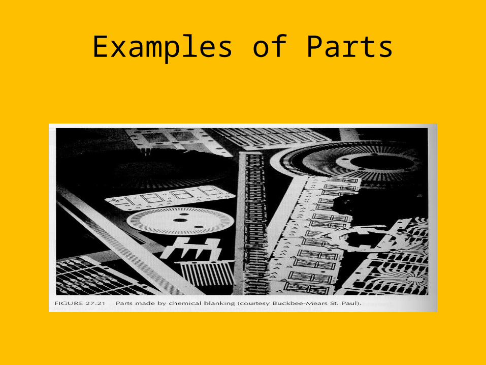
Examples of Parts
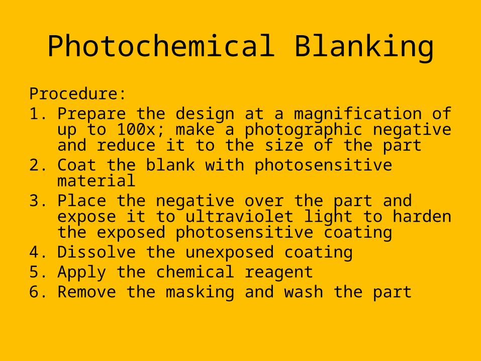
Photochemical BlankingProcedure:1. Prepare the design at a magnification of up to
100x; make a photographic negative and reduce it to the size of the part
2. Coat the blank with photosensitive material3. Place the negative over the part and expose it to
ultraviolet light to harden the exposed photosensitive coating
4. Dissolve the unexposed coating5. Apply the chemical reagent6. Remove the masking and wash the part
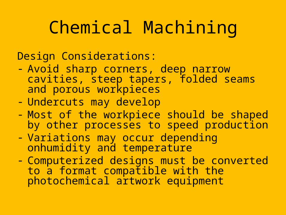
Chemical MachiningDesign Considerations:- Avoid sharp corners, deep narrow cavities, steep
tapers, folded seams and porous workpieces- Undercuts may develop- Most of the workpiece should be shaped by other
processes to speed production- Variations may occur depending onhumidity and
temperature- Computerized designs must be converted to a format
compatible with the photochemical artwork equipment
Electrochemical Machining
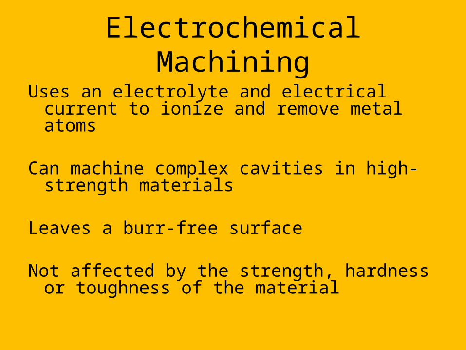
Uses an electrolyte and electrical current to ionize and remove metal atoms
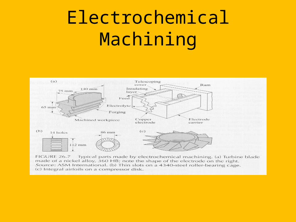
Can machine complex cavities in high-strength materials
Leaves a burr-free surface
Not affected by the strength, hardness or toughness of the material
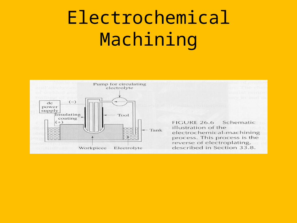
Electrochemical Machining
Electrochemical Machining

Electrochemical Machining
Design Considerations:- The electrolyte erodes away sharp profiles- It is difficult to control electrolyte flow;
irregular cavities may not be formed accurately
- Allow for small taper in holes made this way

Pulsed Electrochemical Machining
A form of electrochemical machining; the current is pulsed to eliminate the need for high electrolyte flow
Improves fatigue life of the part
Electrochemical Grinding
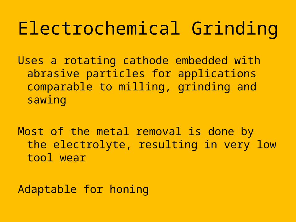
Uses a rotating cathode embedded with abrasive particles for applications comparable to milling, grinding and sawing
Most of the metal removal is done by the electrolyte, resulting in very low tool wear
Adaptable for honing

Electrochemical Grinding
Electrochemical Grinding
Design Considerations:(in addition to those for electrochemical
machining)- Avoid sharp inside radii- Flat surfaces to be ground should be narrower
than the width of the grinding wheel
Electrical-Discharge Machining
Uses a shaped electrode and electric sparks to remove metal; discharges sparks at about 50-500 kHz
A dielectric (nonconductive) fluid removes debris and acts as an insulator until the potential difference is high enough
Can be used on any material that conducts electricity
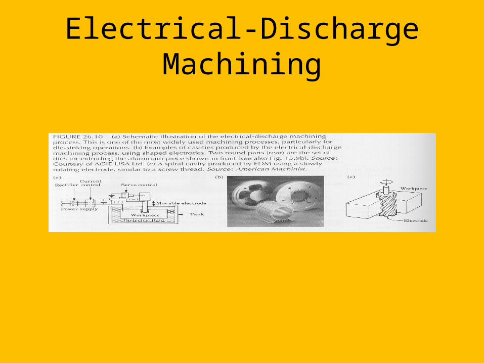
Electrical-Discharge Machining
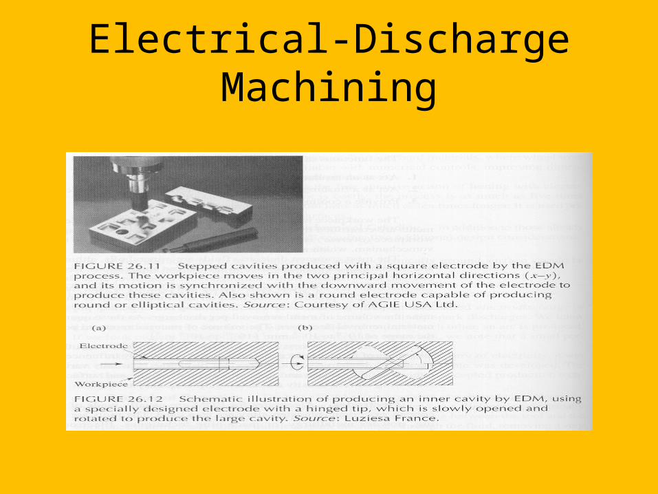
Electrical-Discharge Machining
Electrical-Discharge Machining
Design Considerations:- Design parts so that the electrodes can be
made economically- Avoid deep slots and narrow openings- Do not require very fine surface finish- Most of the material removal should be done
by other processes to speed production
Electrical-Discharge Grinding
The grinding wheel lacks abrasives and removes material by electrical discharges
Can be combined with electrochemical grinding
Can be used for sawing, in which the saw has no teeth
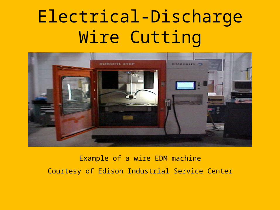
Electrical-Discharge Wire Cutting
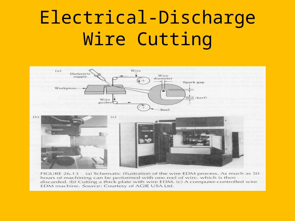
The wire moves through the workpiece like a band saw, removing material by electrical discharge
Dielectric fluid is applied to the work area
The wire is generally used only once; it is inexpensive
Electrical-Discharge Wire Cutting
Electrical-Discharge Wire Cutting
Example of a wire EDM machine
Courtesy of Edison Industrial Service Center

Electrical-Discharge Wire Cutting
Example of a wire EDM machine
Courtesy of Edison Industrial Service Center
Electrical-Discharge Wire Cutting
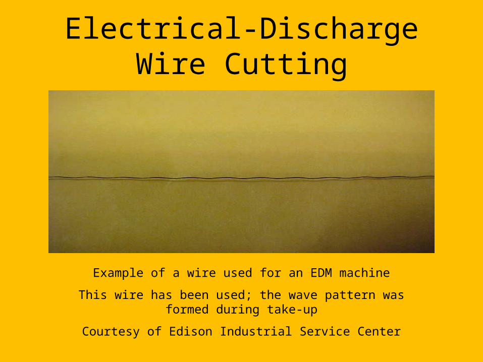
Example of a wire used for an EDM machine
This wire has been used; the wave pattern was formed during take-up
Courtesy of Edison Industrial Service Center
Electrical-Discharge Wire Cutting
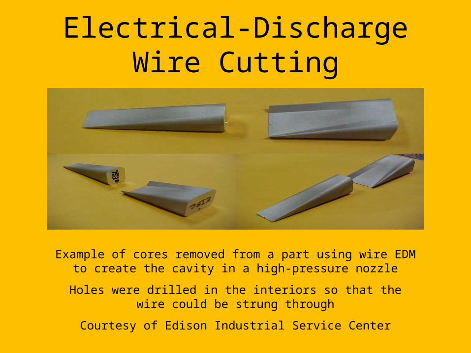
Example of cores removed from a part using wire EDM to create the cavity in a high-pressure nozzle
Holes were drilled in the interiors so that the wire could be strung through
Courtesy of Edison Industrial Service Center
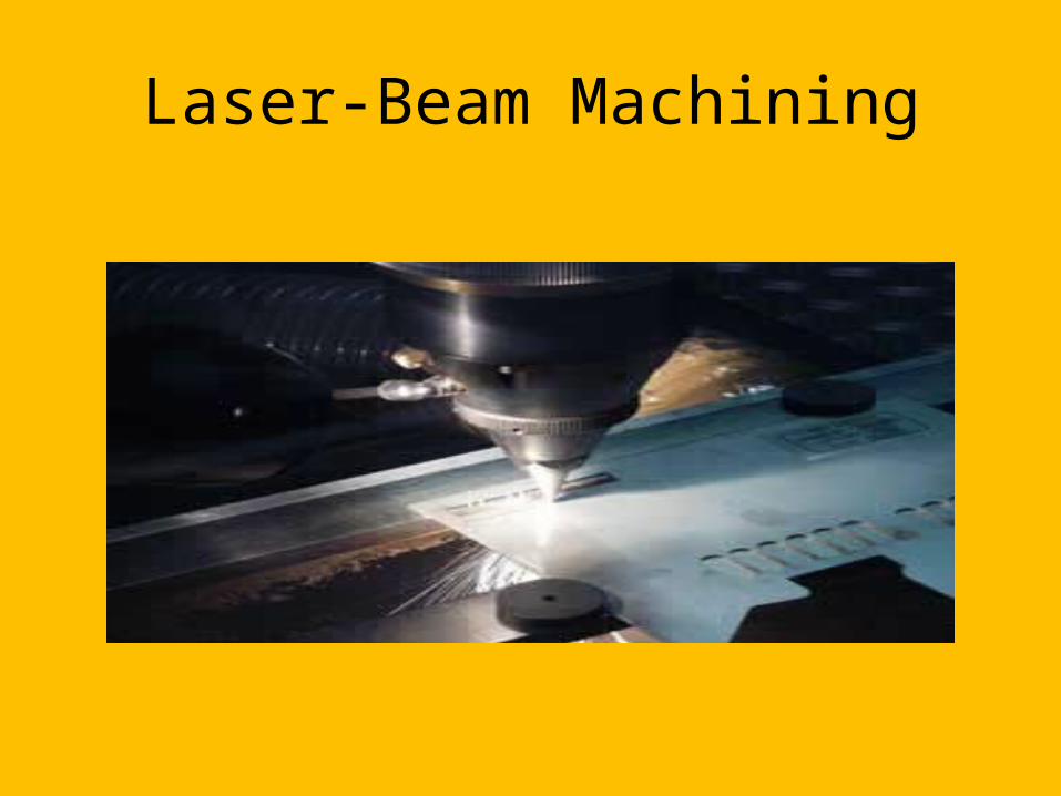
Laser-Beam Machining
Uses a concentrated beam of light to vaporize part of the workpiece
Usually produces a rough surface with a heat-affected zone
Can cut holes as small as .005 mm with depth/diameter ratios of 50:1

Laser-Beam Machining
Laser-Beam Machining
Laser-Beam Machining
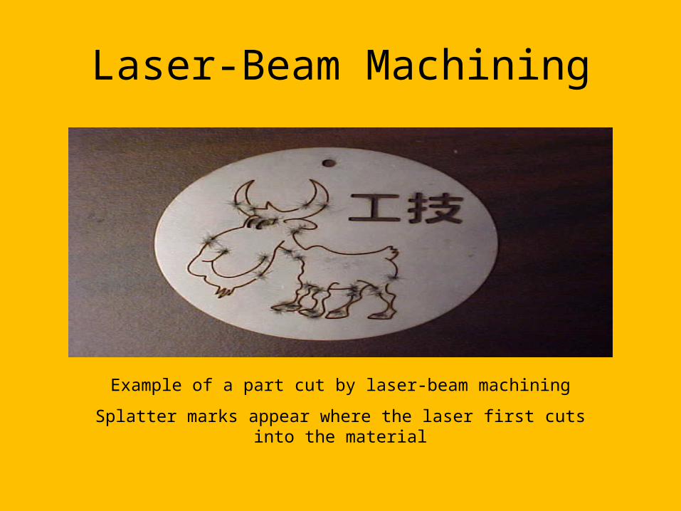
Example of a part cut by laser-beam machining
Splatter marks appear where the laser first cuts into the material
Laser-Beam Machining
Design Considerations:- Non-reflective workpiece surfaces are
preferable- Sharp corners are difficult to produce; deep
cuts produce tapers- Consider the effects of high temperature on
the workpiece material
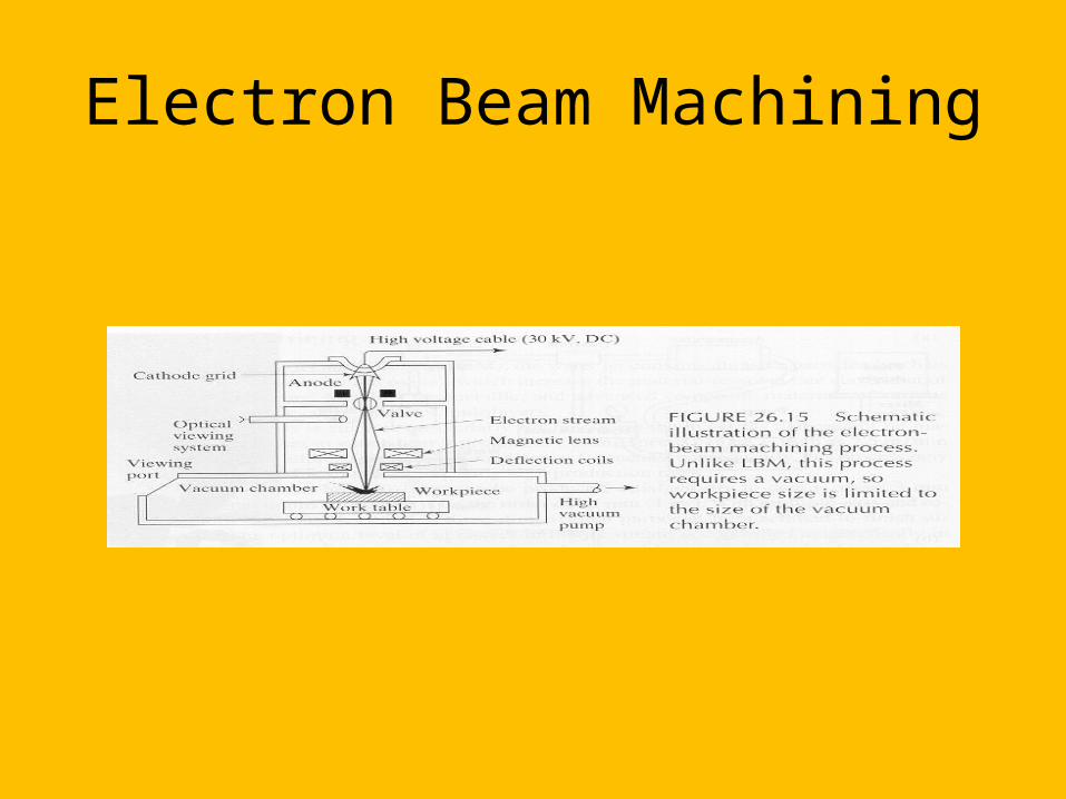
Electron Beam Machining
Vaporizes material using electrons accelerated to 50-80% the speed of light
Produces finer surface finish and narrower cut width than other thermal cutting processes
Requires a vacuum; generates hazardous X rays
Electron Beam Machining
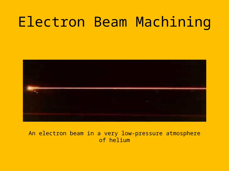
Electron Beam Machining
An electron beam in a very low-pressure atmosphere of helium
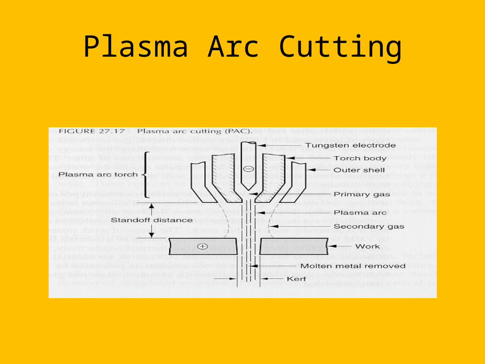
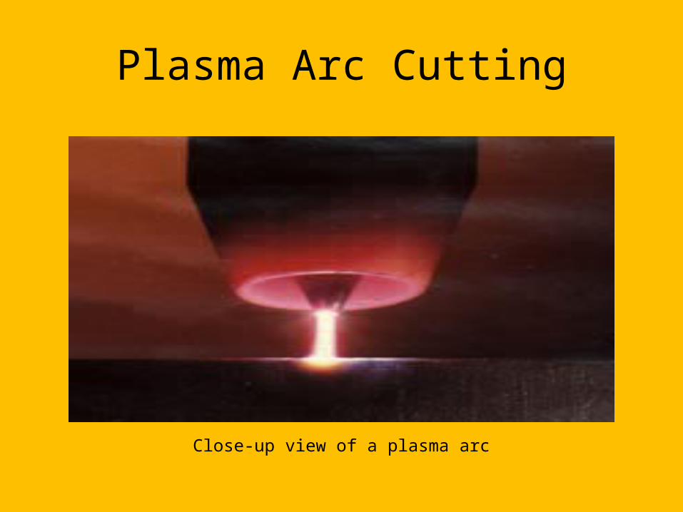
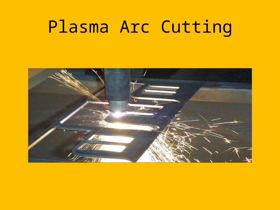
Plasma Arc Cutting
Uses plasma (ionized gas) to rapidly vaporize material
Material removal rates are much higher than those for laser beam machining and electron beam machining; produces good surface finish and thin cut width
Plasma Arc Cutting

Plasma Arc Cutting
Close-up view of a plasma arc
Plasma Arc Cutting
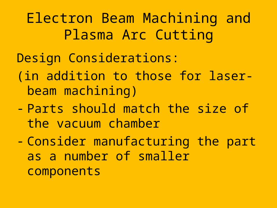
Electron Beam Machining and Plasma Arc Cutting
Design Considerations:(in addition to those for laser-beam machining)- Parts should match the size of the vacuum
chamber- Consider manufacturing the part as a number
of smaller components
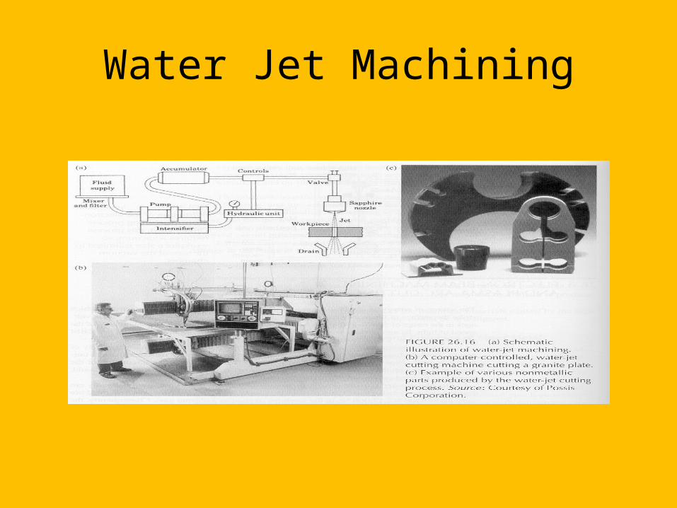
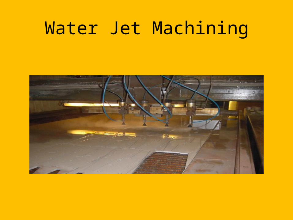
Water Jet Machining
A pressurized jet of water cuts a groove in the material
Effective for many nonmetallic materials
Cuts can be started at any location; does not produce heat; produces very little burring
Water Jet Machining
Water Jet Machining
Abrasive Water Jet Machining
The water jet contains abrasive particles; this increases the material removal rate
Can cut metallic, nonmetallic, and advanced composite materials
Suitable for heat-sensitive materials

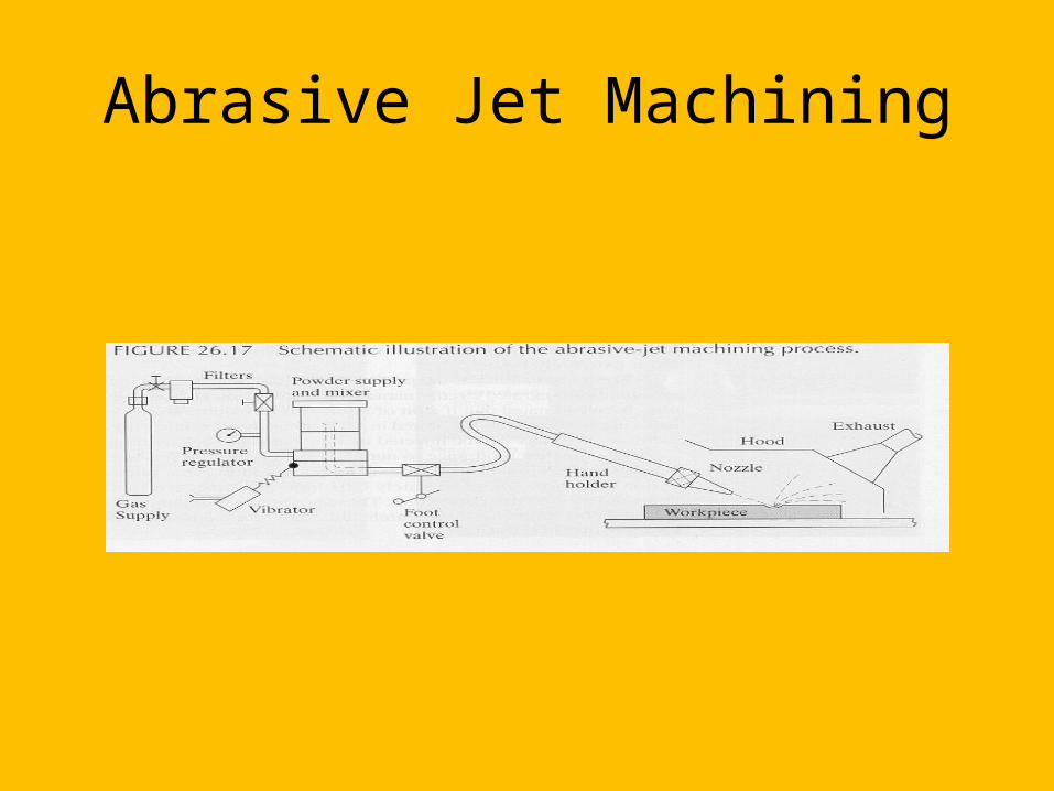
Abrasive Jet Machining
A high-speed jet of dry air, nitrogen or carbon dioxide carries abrasive particles
Good for cutting hard or brittle materials
Can be used for deburring, cleaning, or removing oxides or surface films
Abrasive Jet Machining

Summary
Advanced machining processes offer alternatives where conventional procedures would be insufficient or uneconomical