Embed Size (px)
Citation preview
Advanced Modeling of Electro Motor load
ByKabenla Armah
Supervisor: Jerome JouffroyCo-supervisor: Søren Top
Content
Introduction Modeling method Results Conclusion
Introduction
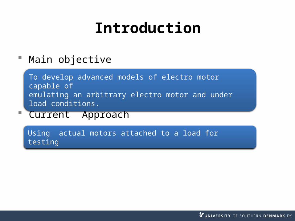
Main objective
Current Approach
To develop advanced models of electro motor capable ofemulating an arbitrary electro motor and under load conditions.
Using actual motors attached to a load for testing
Introduction
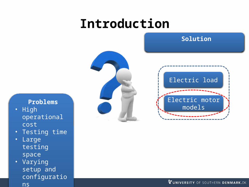
Problems• High
operational cost
• Testing time• Large testing
space• Varying setup
and configurations
Solution
Electric load
Electric motor models
Emulator
Introduction
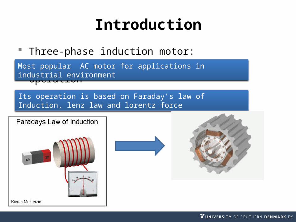
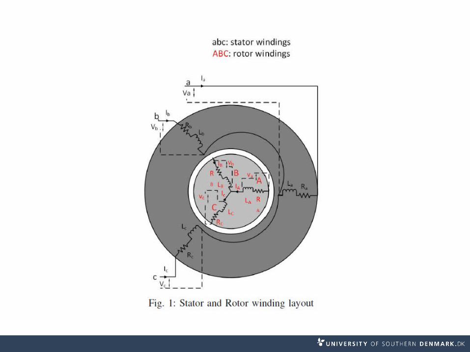
Three-phase induction motor:
OperationMost popular AC motor for applications in industrial environment
Its operation is based on Faraday’s law of Induction, lenz law and lorentz force
Introduction
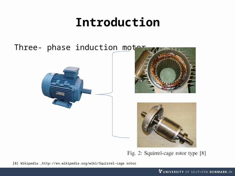
Three- phase induction motor
[8] Wikipedia ,http://en.wikipedia.org/wiki/Squirrel-cage rotor
Introduction
A recap of existing literature tells us [1]-[9]
8 equations needed Reduced number of equations using(DQO
transformation matrix) Balanced system
Problem Unbalanced systems
Modeling Method
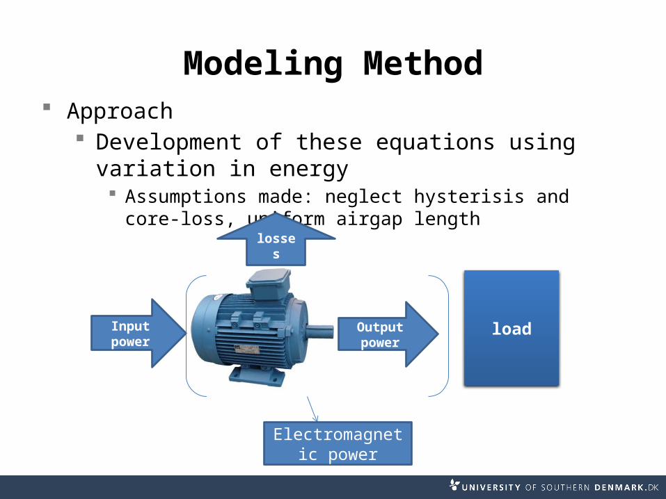
Modeling Method Approach
Development of these equations using variation in energy Assumptions made: neglect hysterisis and core-loss,
uniform airgap length
Input power
Output power
losses
load
Electromagnetic power
Modeling Method
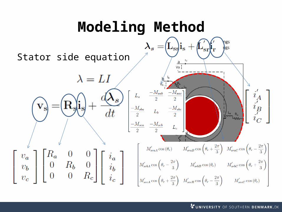
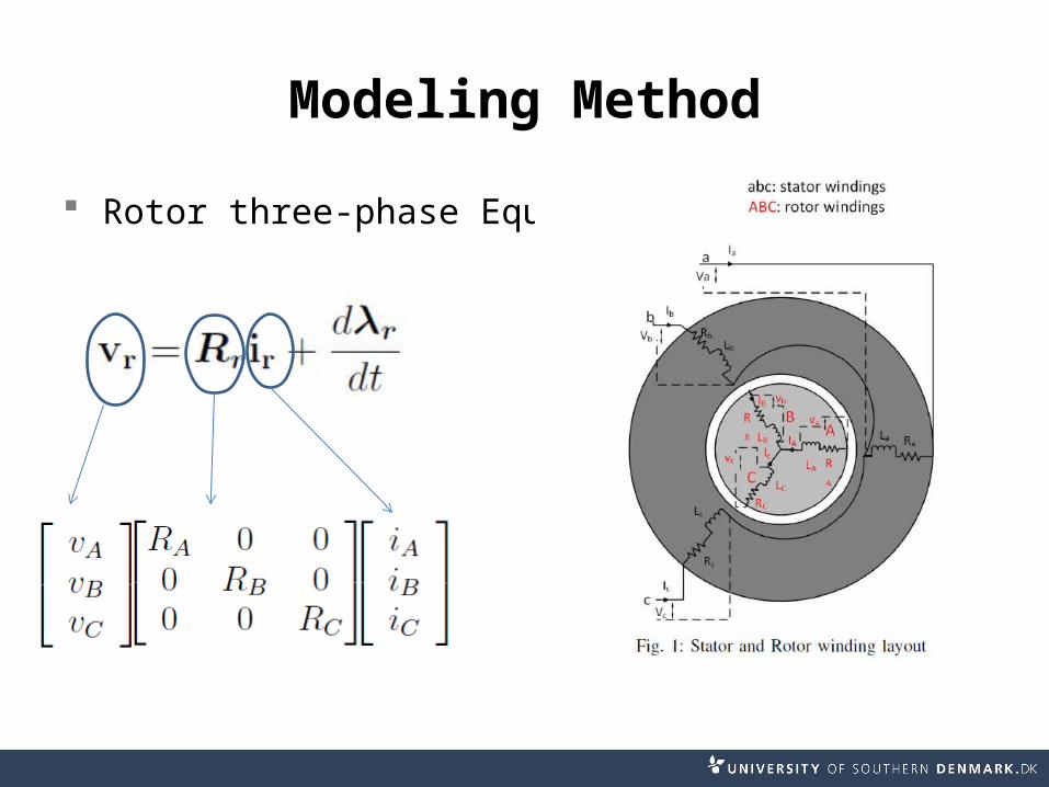
Stator side equation:
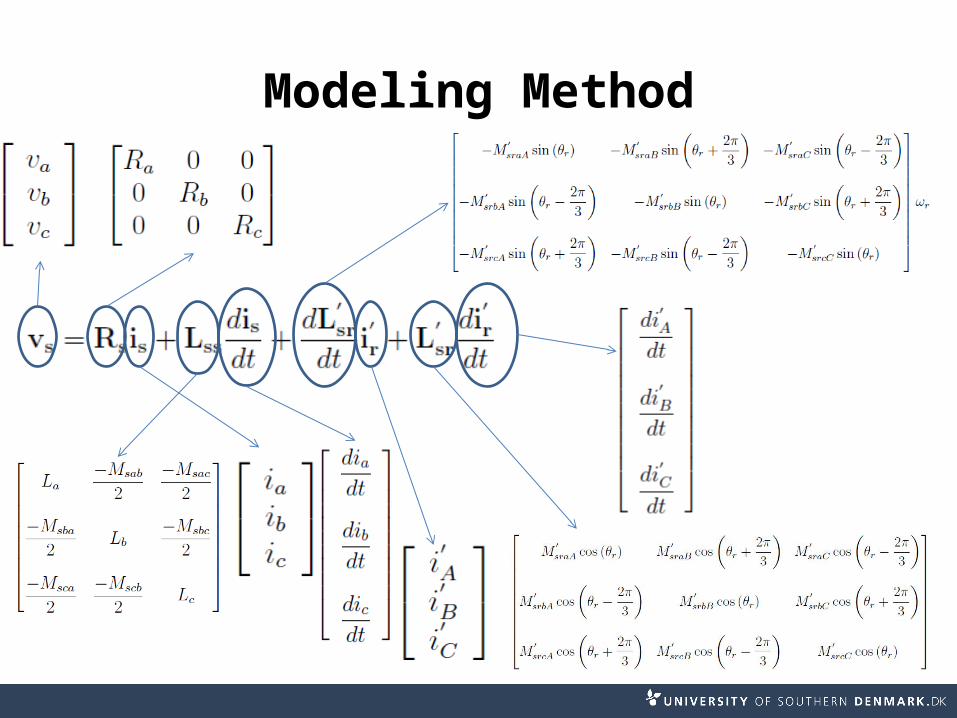
Modeling Method
Modeling Method
0
Modeling Method
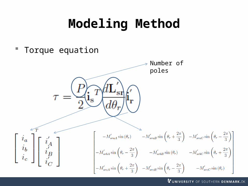
Torque equation
Number of poles
Modeling Method
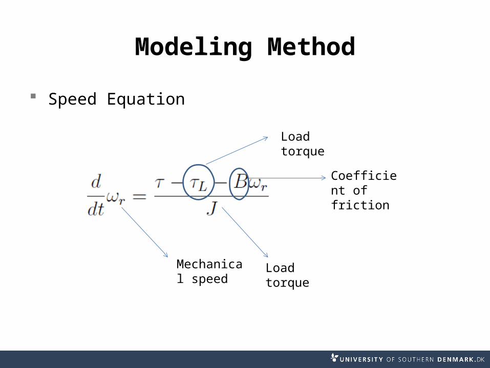
Speed Equation
Load torque
Coefficient of friction
Mechanical speed
Load torque

Results
Results
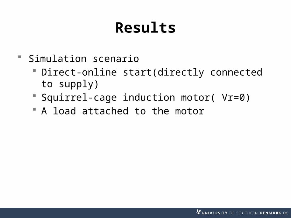
Simulation scenario Direct-online start(directly connected to
supply) Squirrel-cage induction motor( Vr=0) A load attached to the motor

Results
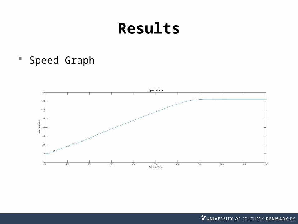
Case 1 Balanced system
Results
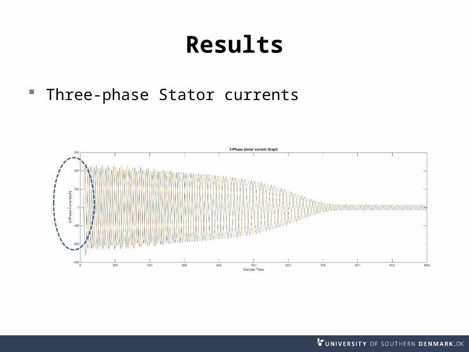
Three-phase Stator currents
Results
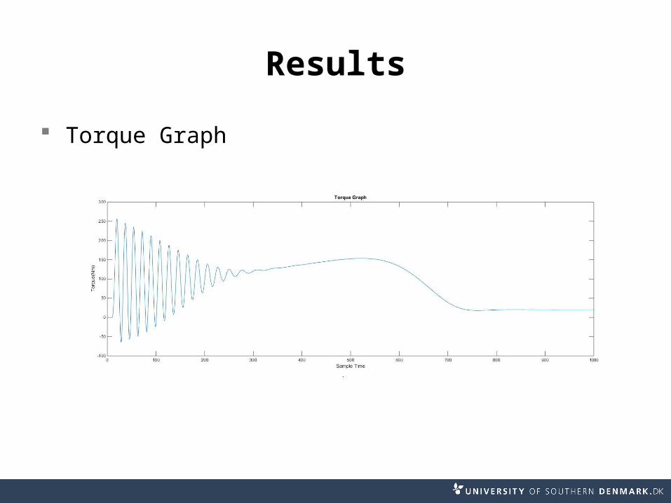
Torque Graph
Results
Speed Graph
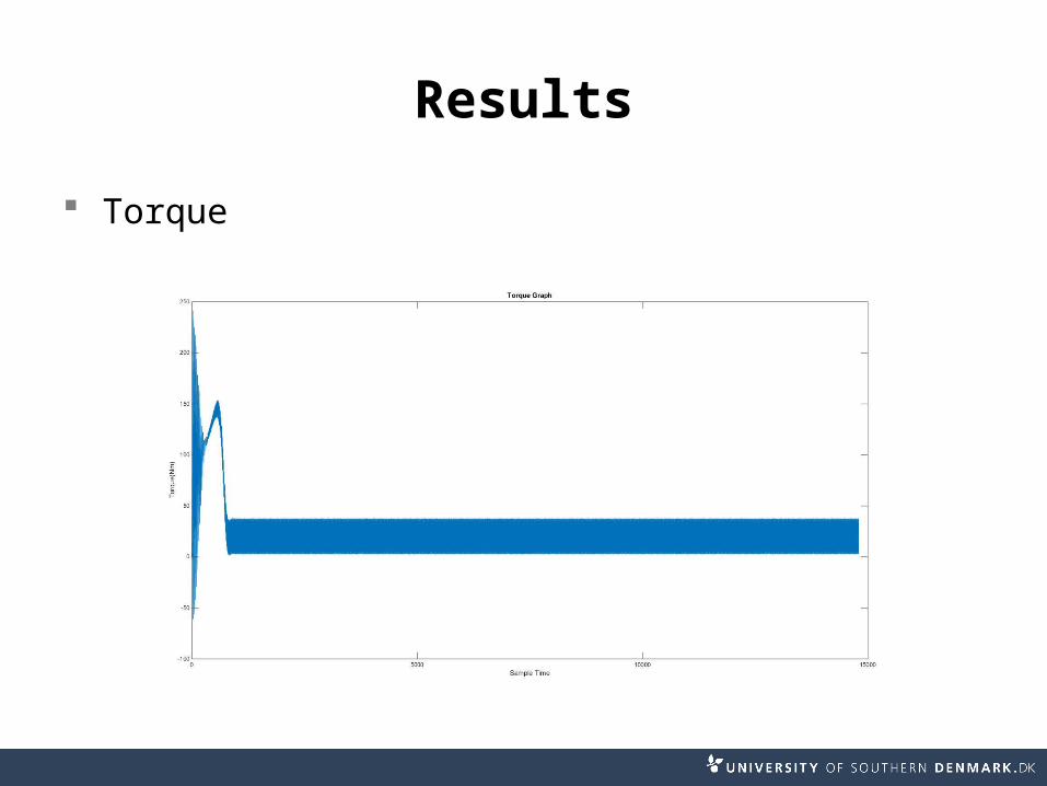
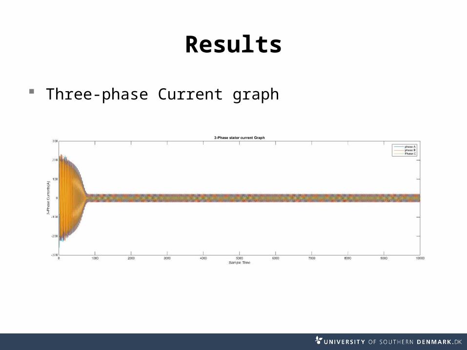
Results Case 2
Voltage imbalance (single phase)
Results
Torque
Results
Three-phase Current graph
Results
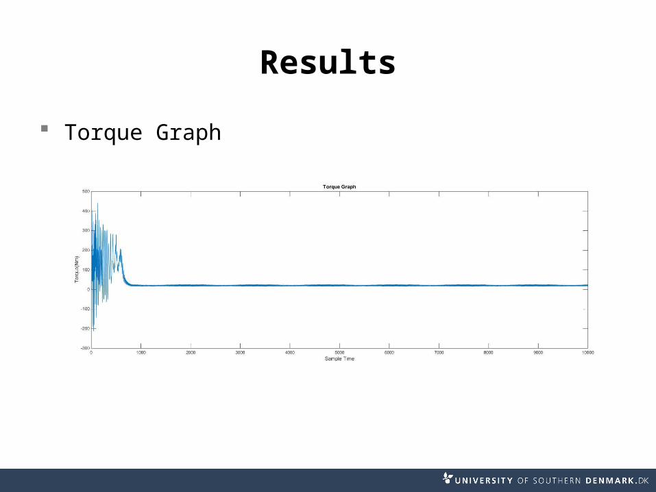
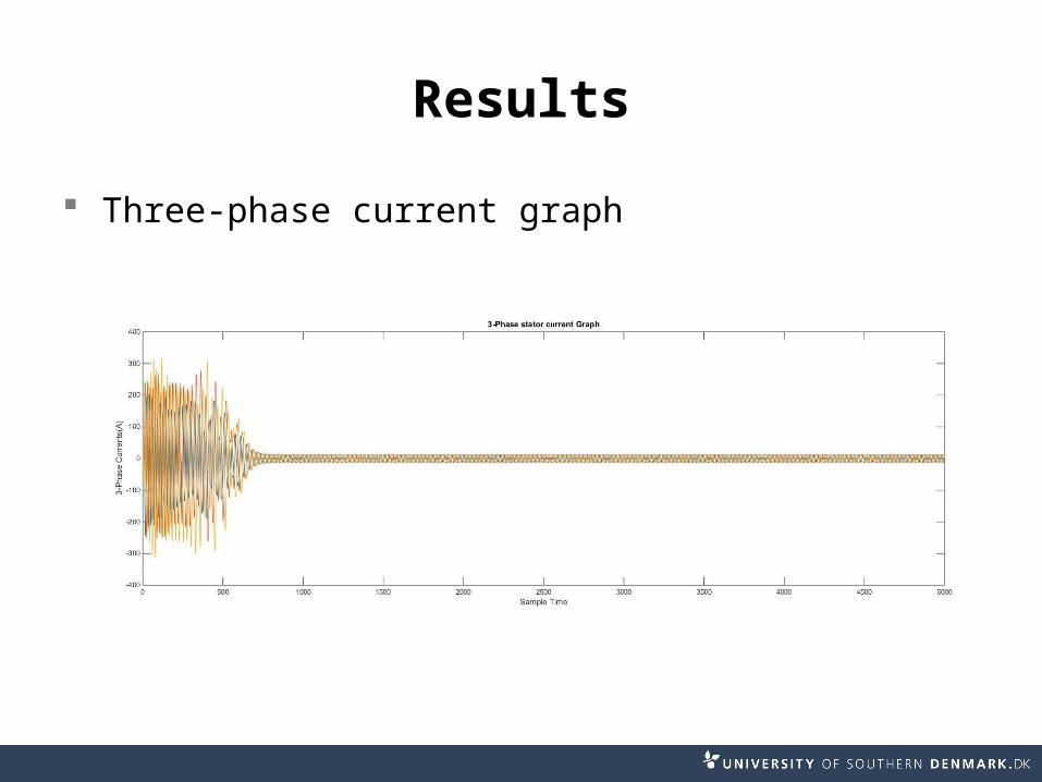
Case 2 Inter-turn short-circuit (Stator Phase A )
Results
Torque Graph
Results
Three-phase current graph
Conclusion
This model Demonstrate the behaviour of the induction
motor under balanced conditions More flexibility in varying parameters to
demonstrate system imbalance

Thank you
References
[1] Dal Y. Ohm, ”Dynamic Model of Induction Motors For Vector Control”, Drivetech, Inc., Blacksburg, Virginia. [2] P.C.Sen,”Principles of Electric Machines and Power Electronics, 2nd Edition”: Wiley, 1996. [3] Erickson, Robert W., Maksimovic, Dragan,”Fundamentals of Power Electronics,2nd Edition”: Springer
2001. [4] A. M. Trzynadlowski, The Field Orientation Principle in Control of Induction Motors :Kluwer Academic
Publishers, 1994. [5] Benot Robyns, Bruno Francois, Philippe Degobert and Jean Paul Hautier,”Vector Control of Induction
Machines, Desensitisation and Optimisation Through Fuzzy Logic”:Springer, 2012. [6] R. J. Lee, P. Pillay and R. G. Harley,” D,Q Reference Frames for the Simulation of Induction Motors”,
Electric Power Systems Research, 8 pp. 15 -26, 1984/85. [7] Chee-Mun Ong,”Dynamic Simulation of Electric Machinery, Using Matlab/Simulink”:Prentice Hall, 1997. [8] Wikipedia ,”http://en.wikipedia.org/wiki/Squirrel-cage rotor” [9] Nidec Corporation,”http://www.nidec.com/en-NA/technology/motor/basic/00026/” [10] TMEIC, ”https://www.tmeic.com/Southeast%20Asia/732-Energy%20Savings%20Wound%20Rotor
%20Induction%20Motor%20Savings- 374” [11] Hsin-Jang Shieh and Kuo-Kai Shyu, ”Nonlinear Sliding-Mode Torque Control with Adaptive Backstepping
Approach for Induction Motor Drive”,IEEE Transactions on Industrial electronics: VOL.46, NO.2, APRIL 1999.
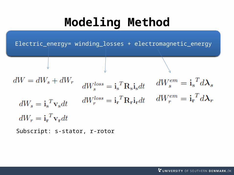
Electric_energy= winding_losses + electromagnetic_energy
Modeling Method
Subscript: s-stator, r-rotor
Modeling Method
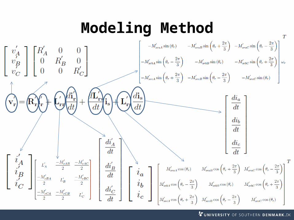
Rotor three-phase Equation: