Embed Size (px)
Citation preview
F AD A08I 327 OFFICE OF THE CHIEF OF NAVAL OPERATIONS WASHINGTON DC F/6 1/3ADVANCED NAVAL VEHICLES CONCEPTS EVALUATION (ANVCE). POINT DESI--ETC(U)JAN 77
UNCLASSIFIED OPNAV"WPOO5
"REV
C NL
EIIIIIh......flf f l, f',fl
EN END
* f f,70

CLAStPIZATION 01 TN!S PAGE (Wh.en 0.. E..tcr.d)_ _ _ _ _ _ _ _ ___
REPRTRZAD:"STRUCC rl.REPRT DOCUMENTATION PAGE sEFOR COMPLETING F.. GOVT ACCESSI . CIDIrENT'S CATALOG Nuw3FeR
WP 005((c))7 T. TTLE (r Su b t e!.-) S. TYPE OF RC,
"& PEIO.) covE"EO
Point Design Description Working PaperS. PERFORMINS ORO. REPORT NUM3BE,
3 . PERFORM!NG ORGANIZATION NAME=
AND ADDRESS 10. PROGRAMW ELE.MENT. PROJEC T. TASK
LIOAREA & WORK UNIT 'jMBER$
.Washington, D.C. 2035031. CONTROLLiNO OFFICE- NA ' A.i: ADOR ES S I" .RO A EL T. R C
-
3 11 Janumy 1977
,14 N-Ift.er t t:3,. n Of/i¢e) I5 SECu-R:TY CLASS (o this repor)
UnclassifiedISd. DECL ASSFI CATION 'OwGRAOING
SCH EDULE
act IS. DISTRIBU.iTION STATEME"iT (o! tH., R.Poet)
Unlimited and approved for Public release.
~DCI
19 SUPPLEMENTARY NOrES
19. KEY WORDS (Continue an pss &iJe if necessary mid identity by bock nucbet)
esAgnanced Naval Vehicle toncepts h A Surface VehicleEvaluation Point Design FormatANOMParametrics and Point Designs, Ar ehicle.... .
This Working Pawe describes the content and format for theWVQB'ointdesign reports. It applies to both Air and Surface Vehicles, Once theparametric design process and state-of-the-art summaries have been com-pleted, it is necessary to focus on a specific design (i.e., some Opointfout of the range of parametric design curves) so that meaningful evalua-tion can be made in three specific areas, namely Military Worth, TedmnicalRisk Assessment and Cost. This Working Paper provides the specific listing
DD 1473 ,O,9 f1o OF I NOV6S IS OBSOLETEUSII
SECURITY CLASSIICATION OP THIS PAGE (Wten Det Enteenwd

SICU~iTY CLASSIFICATICN OF THIS PAGE(W7u, f~ta RMIOV90
20. (cont.)
of products required for the Point Design to be pursued to the FeasibilityDesign Level of Detail.
SCUP4TV CLAS.SIFICAI$Ok' Of TIS PAOL Ef"?-f Li

AVANCED NAVAL VEHICLES CONCEPTS EVALUATION /# (ANVCE)1
POINT DESIGN DESCRIPTIONo
K~INGPAER, 05
REVISION C .
11 JanW ]077
NTIS A&
N~~7I~IIU~'II~flnmnounced
Justifiaation.
By_, __
Distribution/
Availability Codes
Avail and/orDist. special
Advanced Naval Vehicles Concepts EvaluationRoom 812 1300 Wilson Boulevard Arlington, VA 22209
TEL (202)697-1091
80 2 27 146 1

TABLE OF CONTENTS
Page1.0 INTRODUCTION ........ ...................
2.0 VEHICLE GENERAL DESCRIPTION .... .......... ..
2.1 Principal Characteristics ..........
2.2 Performance ....... ..................
2.3 Subsystem Descriptions ..... .............
2.4 Survivability & Vulnerability ............
3.0 LOGISTICS CONSIDERATIONS ..... ..............
3.1 Reliability and Availability ..............
3.2 Maintenance Concept ..... ..............
3.3 Overhaul Concept ...... ................
3.4 Supply Support Concept ..... .............
4.0 TECHNICAL RISK ASSESSMENT .... ...............
APPENDIX A: DESIGN PROCESS ...... ..............
A.1 Approach ........ ....................
A.2 Design Criteria ...... ................
A.3 Design Philosophy ...... ..............
A.4 Trade-Off Studies ...... ..............
i

1
1.0 INTRODUCTION
This Working Paper describes the content and format forthe ANVCE point design reports. It applies to both Air andSurface Vehicles. Once the parametric design process andstate-of-the-art summaries have been completed, it isnecessary to focus on a specific design (i.e., some "point"out of the range of parametric design curves) so that meaning-ful evaluation can be made in three specific areas, namelyMilitary Worth, Technical Risk Assessment and Cost. Thelevel of detail necessary in pursuing a design varies greatlywith the available state-of-the-art, the need for detail andthe real world constraints of cost and time. The designprocess follows fairly well-known phases and is basically thesame whether one is concerned with either Air or Surfacevehicles. Typically the design process proceeds fromConceptual Design Phase, Preliminary Design Phase and on intothe Contract Design Phase. Various documents are availablefor describing the level of detail; one such document usedhere for reference is by Spaulding & Johnson.* For thepurposes of the ANVCE Project it has been taken, consideringall constraints, that the Point Design shall be pursuedessentially to the Feasibility Design stage within theConceptual Design Phase described in the cited Spaulding &Johnson document. This Working Paper provides the specificlisting of products required for the Point Design to bepursued to the Feasibility Design Level of Detail. Thedesign is to be documented in the format provided in thisWorking Paper. A separate report is to be used for eachPoint Design.
2.0 VEHICLE GENERAL DESCRIPTION
This section is to provide in as concise a form as possiblea complete description of the vehicle. Design philosophy,trade studies, etc, are to be contained in Appendix A.
NOTE: Using ANVCE WP-002 "Definition of Terms" as aguide both English and Metric units shall be used indescribing the vehicle.
2.1 PRINCIPAL CHARACTERISTICS
This section shall summarize the principal characteristicsof the vehicle in numerical form. No graphs are to bepresented in this section. While it is difficult to
"Management of Ship Design at the Naval Ship EngineeringCenter (NAVSEC)" by K.B. Spaulding Jr. and A.F. Johnsonpresented at 12th Annual Technical Symposium 1975, ASEWashington, D.C.
1
rI
standardize on a format that would apply to all Air andSurface vehicles, the general format of Table 1 shall befollowed.
The following Table provides the format and many ofthe key overall characteristics needed to describe thevehicle. If the line item does not apply, leave it out;if any important descriptive characteristic is missing,put it in. This list is provided as a guide to emphasizewhere the overall capabilities of the vehicle are to bedescribed. The detailed variations of the performancefeatures along with the vehicle subsystem description areto be provided in Sections 2.2 and 2.3.
In addition to the Table which provides the principalcharacteristics of the vehicle, the following top leveldrawings shall be provided:
(a) General Arrangement Drawings (Inboard Profileand Deck Plans)
(b) Three-view drawing showing positions andidentification of weapons and sensors.
These drawings are to be of sufficient detail to giveoverall dimensions and location of major items (e.g.,location of bulkheads but not furniture).
2.2 VEHICLE PERFORMANCE
The various curves and tables which describe thevehicle's performance should be grouped in this section.For convenience and consistency among the various conceptsthe performance of each vehicle shall be presented in thefollowing sub-sections.
2.2.1 THRUST, DRAG AND POWER
The thrust and drag characteristics of the vehicleshall be summarized here. The following curves shall beprovided as appropriate. All data should be quoted forthe full load displacement (surface vehicles) and takeoffgross weight (air vehicles)
(a) Drag/weight ratio vs speed As a functionof significant
(b) Thrust/weight ratio vs speedwave height
(c) Propulsive efficiency vs speed
2

I. TABU IPRINCIPAL CHAACrDU.ISTICS
Operation *......................... In ten words or less a briefdescription of the intendedmdssion or operation for thovehicle
Dimnsions .................. ........
Length..............................Deam (or span where appropriate) ....Cushion Depth (or strut length).Cushion Area ..................Cushion Pressure (or Wing Loading ....
where appropriate).
Poer Plants
Propulsion Engines .................. Number and TypePropulsors .......................... Number and TypeLift Engines ....................... Number and Type where applicableLift Fans ........................... Number and Type where applicable
Systems
Crew and Complement ................. Number and TypeFuel ................................ Weight and Volume Tankage
Electrical .......................... "Ten words or less" description(include capacity of system whenknown)
Hydraulic .......................... . "Ten words or less" description(include capacity of system whenS known)
Steering ............................ "Ten words or less" drescription(include capacity of systcm whenknown)
Other Auxiliary Systems ............. "Ten words or less" description
(include capacity of system when -known)
Speciel Systems (e.g. OLC. HAS$..)... "Ten words or less" description(include capacity of system whenknown)
Weights
full Load Weight (Displacement) .....tepty Weight ........................Fuel ................................Other Loads .........................
Nobility Performance Sumary
Ma. Speed (Calm Water) .............Mn. Speed (xx metres sig. wave height)Hump Msrgin (in what wave height) ....lest Range Speed (Calm Water) .......lest Rafts Speed (Sig. Wave height)..Climb Speed ........................Rate of Climb .....................T.O. Distance (Calm & Rough Water)...Time to accelerate to cruise speed ..TIlme to accelerate to ma. speed ....Time to decelerate ..................Stopping Distance .................. .
turming radius at speed ...........Altitude limits ....................
2~a .............................ZM4deaM6e...........................
cmbet System "
Atmet ............................ Nimber and type (include launcher,
fire control and number of reloads)SOno. .... Um.. ..... Nuber an typeCemmwld and Control..................TypeSecondary Vehicles *o......d...W. Number and type
This Table has been written essentially for Surfece Vehicles (exceptfe some obvious line items) and is meant to be indicative of thevehicle characteristics. Gas containment volume (for LTA); foil spanai strut d.pth (for hydrooli) etc. are obvious additions forether vehicles. Coinnn sense should prevail here on the line item*.3.
I
The speed range shall be from zero speed to maximumspeed. The thrust/weight curves are to be provided foravailable ratings for the engines; e.g., maximum continuous,maximum intermittent. For consistency the thrust curves areto be presented for a standard 590 F (150 C) day and a 800 F(26.70 C) day. For air vehicles, the curves are to bepresented for both sea level and some specified operatingaltitude as appropriate.
For those vehicles that require additional power(other than electrical and auxiliary systems power) forthe vehicle concept to function, the additional presentationis required
WV(d)-P vs speed
where !, is as defined in ANVCE WP-002 and includes liftpower, PBLC power and ride control power.
The components of drag and power are to be includedin the curves or provided in a separate plot for clarity.
For surface vehicles, the following derived curves
are required B
(e) Maximum sustained speed vs significant wave height.
A discussion should be provided indicating thecondition which limits the speed (e.g., added drag, motion,structural loading, etc.).
These envelopes are to be included for all modes inmulti-modal vehicles (e.g., foilborne, hullborne, on-cushion,off-cushion).
For air vehicles, the following derived envelopes areto be included
(f) Maximum sustained speed vs altitude. B
For WIG craft a combination of (e) and (f) may berequired to describe the performance.
4
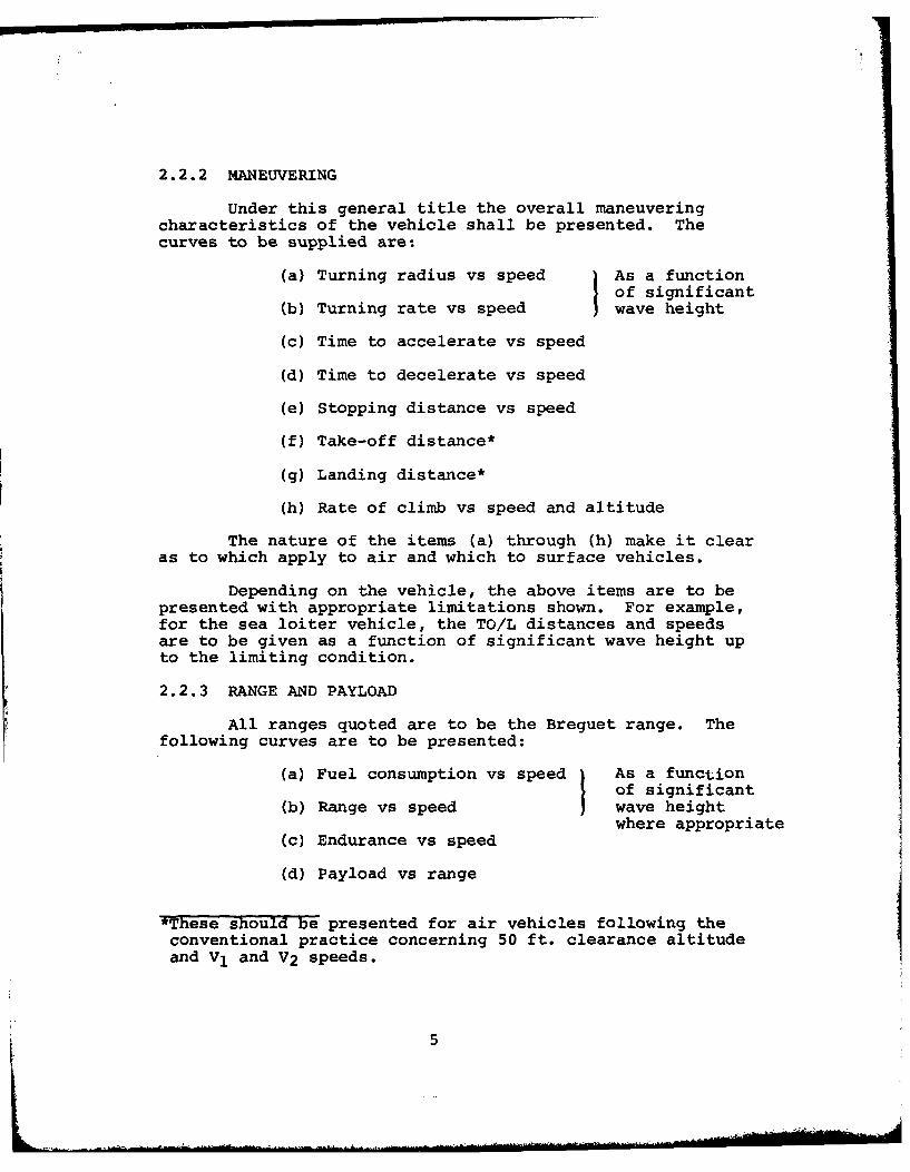
2.2.2 MANEUVERING
Under this general title the overall maneuveringcharacteristics of the vehicle shall be presented. Thecurves to be supplied are:
(a) Turning radius vs speed As a functionof significant
(b) Turning rate vs speed wave height
(c) Time to accelerate vs speed
(d) Time to decelerate vs speed
(e) Stopping distance vs speed
(f) Take-off distance*
(g) Landing distance*
(h) Rate of climb vs speed and altitude
The nature of the items (a) through (h) make it clear
as to which apply to air and which to surface vehicles.
Depending on the vehicle, the above items are to bepresented with appropriate limitations shown. For example,for the sea loiter vehicle, the TO/L distances and speedsare to be given as a function of significant wave height upto the limiting condition.
2.2.3 RANGE AND PAYLOAD
All ranges quoted are to be the Breguet range. Thefollowing curves are to be presented:
(a) Fuel consumption vs speed As a functionof significant
(b) Range vs speed wave heightwhere appropriate
(c) Endurance vs speed
(d) Payload vs range
*These should be presented for air vehicles following theconventional practice concerning 50 ft. clearance altitudeand V1 and V2 speeds.
5

For consistency, the fuel consumption shall bepresented as nautical miles/ton (and kilometers/metric ton)of fuel consumed.
Limitations of power ratings and weather are to beincluded in any such payload-range curves. Payload-rangecurves should assume a direct weight tradeoff betweenfuel and payload.
Wherever possible, conversion values to time-onstation and endurance are to be given, e.g., what is therange of the VSTOL sea loiter if it makes so many TO&Lon water?
2.2.4 WEIGHT AND VOLUME SUMMARY
This section shall contain the complete descriptionof the weight and volume breakdown of the vehicle in asmuch detail as is available at the feasibility designstate. Pending further discussion relative to anydifferences between air and surface vehicles, the shipwork breakdown structure (SWBS) as defined in NAVSHIPS0900-039-9010 shall be used for the presentation of allweights for the ANVCE Project.
For consistency, the weight summary shall bepresented in the format shown in Table 2a and the volumesummary shall be presented in the format shown in Table 2b.
For Feasibility Design, it is sufficient to provideinformation to the "hundred digit" lever only as shown.The one exception is in the lift system (Group 567)because of the particular interest in that sub-category.
2.2.5 STABILITY
The purpose of this section is to present the overallstability characteristics of the vehicle, rather thandetailed treatment of equations of motion. The items ofconcern relate to whether the vehicle is statically anddynamically stable in its operating modes, the vehicle'smotion characteristics, especially in bad weather, andits damage stability characteristics (which apply to bothsurface vehicles and those air vehicles required to sit onthe water).
6
I ' 1&- - I
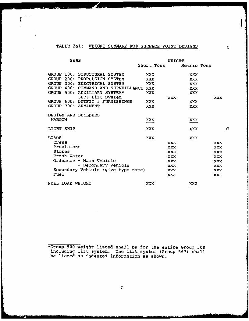
TABLE 2al: WEIGHT SUMMARY FOR SURFACE POINT DESIGNS C
SWBS WEIGHTShort Tons Metric Tons
GROUP 100: STRUCTURAL SYSTEM XXX XXXGROUP 200: PROPULSION SYSTEM XXX XXXGROUP 300: ELECTRICAL SYSTEM XXX XXXGROUP 400: COMMAND AND SURVEILLANCE XXX XXXGROUP 500: AUXILIARY SYSTEM* XXX XXX
567: Lift System xxx xxxGROUP 600: OUTFIT & FURNISHINGS XXX XXXGROUP 700: ARMAMENT XXX XXX
DESIGN AND BUILDERSMARGIN XXX XXX
LIGHT SHIP XXX XXX C
LOADS XXX XXXCrews xxx xxxProvisions xxx xxxStores xxx xxxFresh Water xxx xxxOrdnance - Main Vehicle xxx xxx
- Secondary Vehicle xxx xxxSecondary Vehicle (give type name) xxx xxxFuel xxx xxx
FULL LOAD WEIGHT XXX XXX
*Group 500 weight listed shall be for the entire Group 500including lift system. The lift system (Group 567) shallbe listed as indented information as shown.
7

TABLE 2a2: WEIGHT SUMMARY FOR AIR POINT DESIGNS C
WEIGHT
Short Tons Metric Tons
structure XXX XXXPropulsion Group XXX XXXElectrical Group XXX XXXAvionics (Incl. NAV and IC) XXX XXX
Navigation and Interior Comm. XXX XXXAuxiliary Systems XXX XXXFurnishings and Equipment Group XXX XXXArmament XXX XXXLight Vehicle(without margin) XX XXXMargin (10% Light Vehicle) XXX XXXLight Vehicle(with Margin) XXX XXX
LOADSCrew and Effects XXX XXXProvisions XXX XXXStores XXX XXXFresh Water XXX XXXDisposable Ordnance & Sensors XXX XXXSecondary Vehicle XXX XXXRPV Fuel XXX XXXVehicle Fuel XXX XXXTotal Loads XX XXX
Take Off Gross Weight XXX XXX
Payload XXX XXX
T -®-9+ 08+ G +0+)
Useful Load XXX XXX
Empty Weight XXX XXX
7a

TABLE 2b: VOLUME SUMMARY
Internal VolumeFunction (Cubic Meters)
Main Propulsion (including mainmachinery box, uptakes, shafting) XXX
Lift System XXX
Personnel (including living,messing and all personnel support andstorage) XXX
Auxiliary and Electrical (machineryspaces other than main propulsionand lift outside main machinery box) XXX
Payload (internal volume only) XXX
Other (including passageways, maintenancespaces and all other spaces not includedin above) XXX
Total Enclosed Volume XXX
8

TABLE 2bl: VOLUME SUMMARY FOR AIR POINT DESIGNS C
Function Internal Volume(Cubic Meters)
Propulsion XXX
Auxiliary and Electrical XXX
Personnel (including living, messing XXXand all personnel support and stowage)
Payload (internal volume only) XXX
Tankage XXX
Other (including passageways, maintenance XXXspace and all other spaces notincluded in above)
Total Enclosed Volume XXX
8a
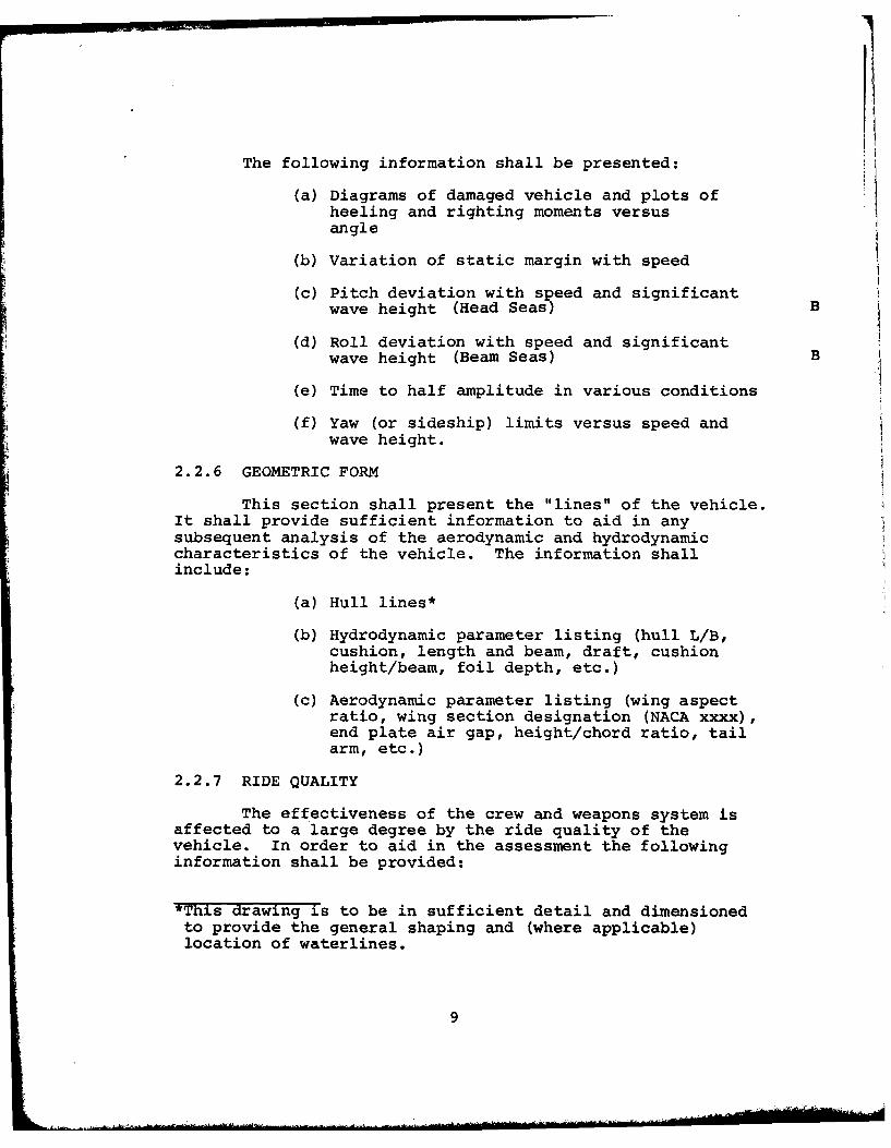
The following information shall be presented:
(a) Diagrams of damaged vehicle and plots ofheeling and righting moments versusangle
(b) Variation of static margin with speed
(c) Pitch deviation with speed and significantwave height (Head Seas) B
(d) Roll deviation with speed and significant
wave height (Beam Seas) B
(e) Time to half amplitude in various conditions
(f) Yaw (or sideship) limits versus speed andwave height.
2.2.6 GEOMETRIC FORM
This section shall present the "lines" of the vehicle.It shall provide sufficient information to aid in anysubsequent analysis of the aerodynamic and hydrodynamiccharacteristics of the vehicle. The information shallinclude:
(a) Hull lines*
(b) Hydrodynamic parameter listing (hull L/B,cushion, length and beam, draft, cushionheight/beam, foil depth, etc.)
(c) Aerodynamic parameter listing (wing aspectratio, wing section designation (NACA xxxx),end plate air gap, height/chord ratio, tailarm, etc.)
2.2.7 RIDE QUALITY
The effectiveness of the crew and weapons system isaffected to a large degree by the ride quality of thevehicle. In order to aid in the assessment the followinginformation shall be provided:
*This drawing is to be in sufficient detail and dimensionedto provide the general shaping and (where applicable)location of waterlines.
9
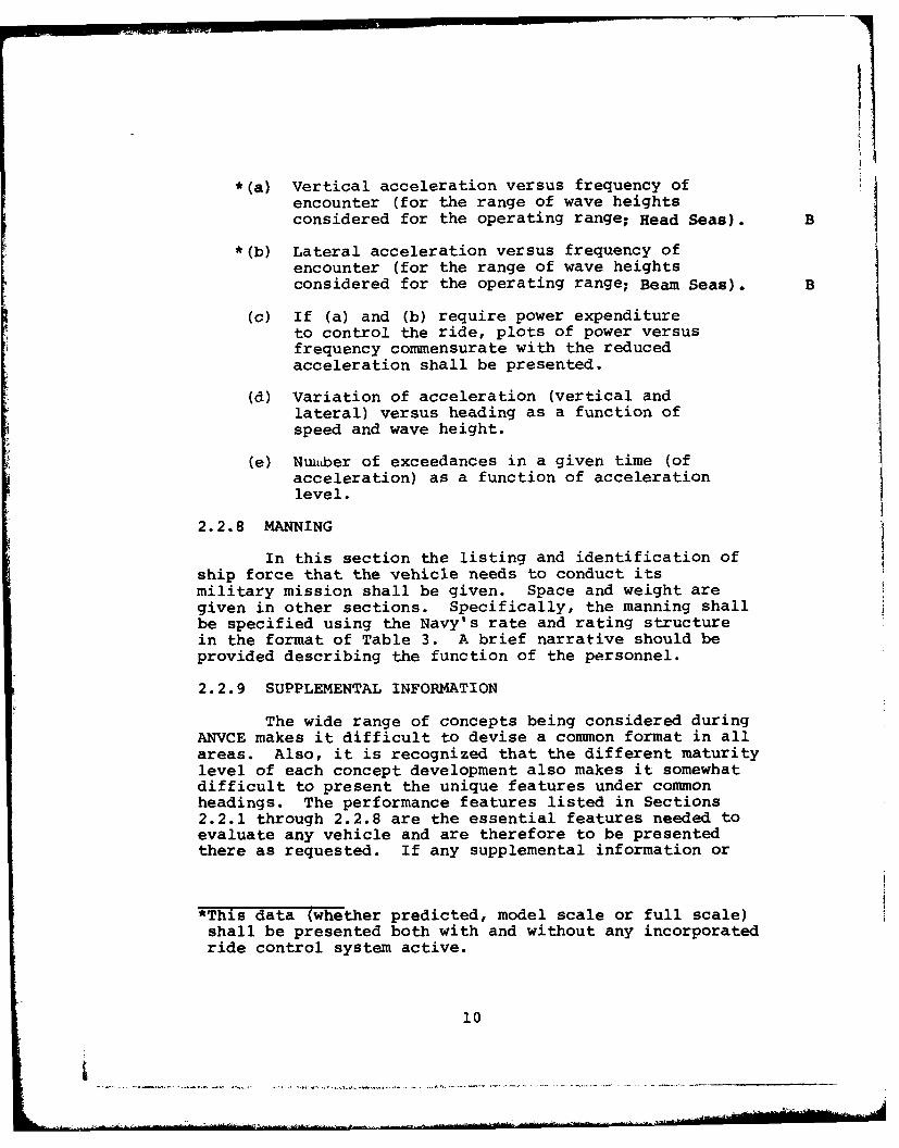
*(a) Vertical acceleration versus frequency ofencounter (for the range of wave heightsconsidered for the operating range; Head Seas). B
*(b) Lateral acceleration versus frequency ofencounter (for the range of wave heightsconsidered for the operating range; Beam Seas). B
(c) If (a) and (b) require power expenditureto control the ride, plots of power versusfrequency commensurate with the reducedacceleration shall be presented.
(d) Variation of acceleration (vertical andlateral) versus heading as a function ofspeed and wave height.
(e) Nuiaber of exceedances in a given time (ofacceleration) as a function of accelerationlevel.
2.2.8 MANNING
In this section the listing and identification of
ship force that the vehicle needs to conduct itsmilitary mission shall be given. Space and weight aregiven in other sections. Specifically, the manning shallbe specified using the Navy's rate and rating structurein the format of Table 3. A brief narrative should beprovided describing the function of the personnel.
2.2.9 SUPPLEMENTAL INFORMATION
The wide range of concepts being considered duringANVCE makes it difficult to devise a common format in allareas. Also, it is recognized that the different maturitylevel of each concept development also makes it somewhatdifficult to present the unique features under commonheadings. The performance features listed in Sections2.2.1 through 2.2.8 are the essential features needed toevaluate any vehicle and are therefore to be presentedthere as requested. If any supplemental information or
*This data (whether predicted, model scale or full scale)shall be presented both with and without any incorporatedride control system active.
10
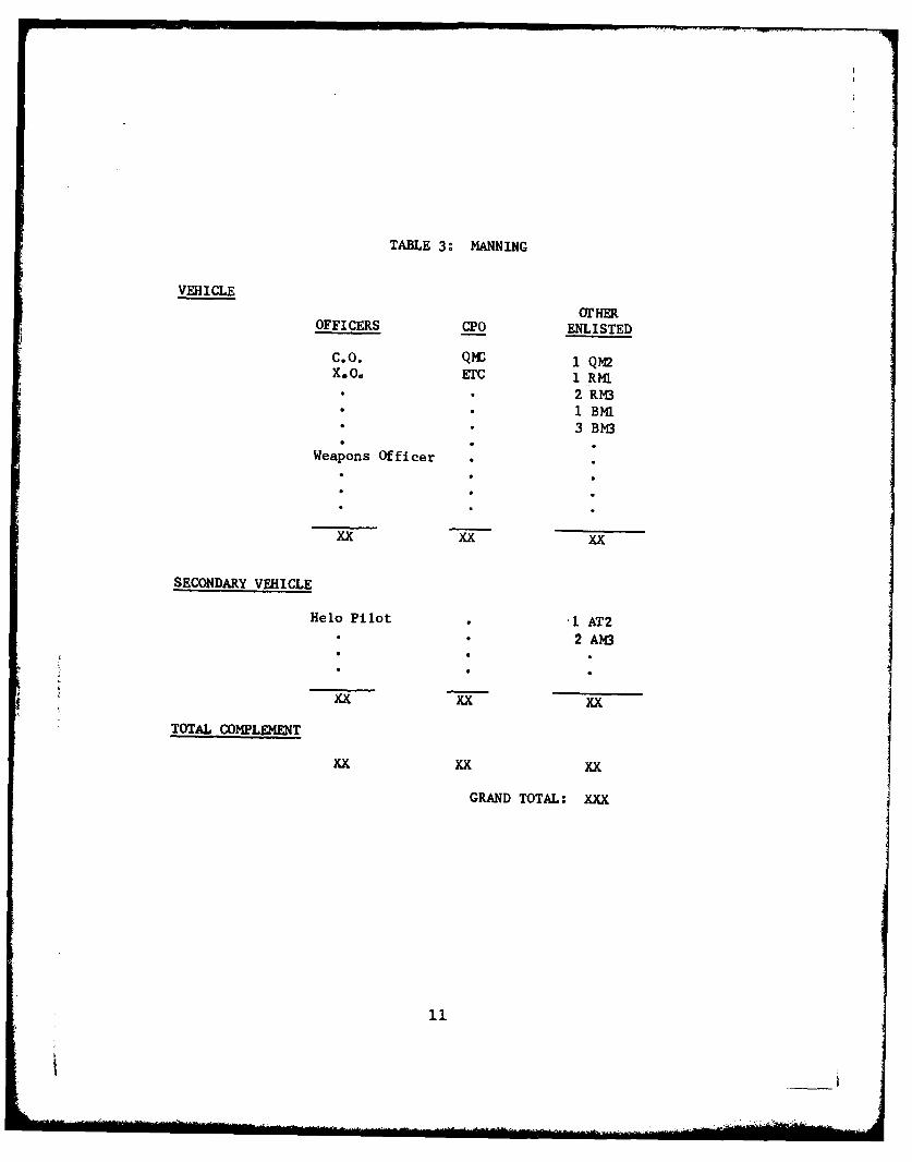
TABLE 3: MANNING
VEHICLE
OTHEROFFICERS CPO ENLISTED
C.O. Qmc 1 qmX6O0 ETC 1 RKl
• • 2 RM3S•1 BMI* 3 BM3
Weapons Officer
xx xx xx
SECONDARY VEHICLE
Helo Pilot .1 AT2S•2 AM3
xx xx xx
TOTAL COMPLEMENT
xxxx xx
GRAND TOTAL: XXx
11

unique features of a particular vehicle need to beemphasized or brought to the attention of the ANVCEProject for specific consideration such information isto be grouped in this section for proper identification.
2.3 SHIP SUBSYSTEM DESCRIPTIONS
The capabilities of the vehicle in terms of itsperformance and overall features shall be provided insection 2.2. This major section of the PointDesign Description shall be restricted to the internalsubsystem descriptions. These descriptions shall com-prise both concise narrative and supporting drawings.
2.3.1 STRUCTURE
The following shall be provided to describe thestructure of the vehicle:
(a) A two to three page summary description ofthe key features of the structure identifyingtype of material(s), method of construction,method of production (aerospace, shipbuilding,other).
(b) A general structural arrangement drawingshowing main components and type of con-struction. Where possible, dimensions andsizes should be given (e.g., thin-gaugealuminum requiring special skills in fabri-cation or thick-sheet construction allowinglesser quality control).*
(c) Sketches (not necessarily to scale)illustrating key features of the structuralarrangement (e.g., how a porous compositeBLC surface on a wing will be integratedwith remainder of metal structure).
(d) Rough estimates of percentage weight break-down of major elements of structure withinthe Group 100 weight estimate (e.g., whatpercentage is aluminum, what percentage iscomposite, etc.).
*Note that in the case of hydrofoils only a generalnotation of struts and foils is needed here. Thecorresponding structural information for these areprovided in the section on Lift Systems in accordancewith the SWBS.
12
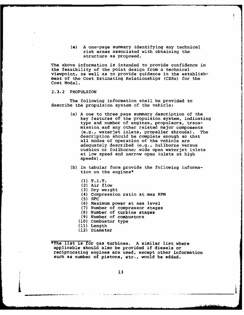
(e) A one-page summary identifying any technicalrisk areas associated with obtaining thestructure as proposed.
The above information is intended to provide confidence inthe feasibility of the point design from a technicalviewpoint, as well as to provide guidance in the establish-ment of the Cost Estimating Relationships (CERs) for theCost Model.
2.3.2 PROPULSION
The following information shall be provided todescribe the propulsion system of the vehicle:
(a) A one to three page summary description of thekey features of the propulsion system, indicatingtype and number of engines, propulsors, trans-mission and any other related major components(e.g., waterjet inlets, propeller shrouds). Thedescription should be complete enough so thatall modes of operation of the vehicle areadequately described (e.g., hullborne versuscushion or foilborne; wide open waterjet inletsat low speed and narrow open inlets at highspeeds).
(b) In tabular form provide the following informa-tion on the engines*
(1) T.I.T.(2) Air flow(3) Dry weight(4) Compression ratio at max RPM(5) SFC(6) Maximum power at sea level(7) Number of compressor stages(8) Number of turbine stages(9) Number of combustors
(10) Combustor type(11) Length(12) Diameter
*The list is for gas turbines. A similar list whereapplicable should also be provided if diesels orreciprocating engines are used, except other informationsuch as number of pistons, etc., would be added.
13
I _ _ _ _I_ _ _ _
I
(c) A general arrangement drawing showing themain components and their location within thevehicle. Where possible, dimensions, sizes,and other key information should be shown(e.g., RPM of transmission at various pointsfrom engine to propulsor).
(d) A tabulation of the characteristics of the mainelements such as:
(1) Waterjet Pump (give size, power,specific speed, etc).
(2) Propeller (give diameter, number of blades,disc loading, power absorption, etc.).
(3) Nuclear reactor (give type, specific weight,temperatures, etc.).
(4) Transmission (power levels, RPM type ofgear boxes, etc.).
(e) Sketches (not necessarily to scale) illustratingkey features of the propulsion system (e.g.,demister schemes, reactor schematic, inletdoors).
(f) Rough estimates of percentage weight breakdownof major elements of propulsion within Group200 (e.g., what percentage is engines, trans-mission, propulsors).
(g) A one-page summary identifying any technicalrisk areas associated with obtaining thepropulsion scheme.
As in the case of structure, the above information guidesthe establishment of confidence in the Cost EstimatingRelationships (CERs) for the Cost Model.
2.3.3 ELECTRICAL SYSTEM
The following shall be provided to describe theelectrical system of the vehicle:
(a) A one to two page summary description of thekey features of the electrical system,identifying type of system (e.g., gas turbinedriven generator) and type of components(shipboard wiring or aircraft aluminum wiring,etc.).
14
(b) A general schematic showing main componentsand mode of operation.
(c) A general arrangement drawing showing locationof componenets in the vehicle.
(d) A tabulation of key information such asfrequency, power levels and redundancy factors.
(e) Rough estimates of percentage weight breakdownof major components with Group 300 (e.g., whatpercentage is wiring, what percentage isgenerator set, etc.).
(f) A one-page summary identifying any risk areasassociated with the electrical system asproposed, (e.g., are components availabletoday or are special lightweight generatorsrequired to be developed).
2.3.4 COMMAND, CONTROL AND COMMUNICATION (C3)
(a) A list of equipment for command, control,communications functions.
(b) A table listing weight and volume for C3
subsystems, and weight for IC and navigationfunctions.
(c) A general arrangement drawing showing thelocation of the C3 system major componentswithin the vehicle.
(d) A one-page summary identifying any risk areasassociated with the C3 system.
(e) An identification either by drawing, tabulationor statement as to how much of the systemsrelated to the vehicle functions as a plat-form and how much is related to the militaryoperation functions. (Information to beprovided by component identification andpercentage weight and volume.)
2.3.5 AUXILIARY SYSTEM
The presentation of information in this section isto be presented in two parts, viz:
15
i _ __
i_

2.3.5.1 Auxiliary System Less Lift System2.3.5.2 Lift System
In this manner, proper accounting can be kept pertainingto weight, cost and risk assessment.
2.3.5.1 AUXILIARY SYSTEM LESS LIFT SYSTEM
The following information shall be provided todescribe the HVAC, hydraulic, pneumatic, steering, etc.,systems onboard the vehicle:
(a) General arrangement drawings of each of the mainauxiliary systems showing location of majorcomponents.
(b) An identification by tabular format of the basiccharacteristics of the major components (e.g.,3000 psi hydraulic pumps and motors, 10 gallonreservoirs; etc.).
(c) A rough estimate of the percentage weight ofeach major auxiliary system comprising the totalweight of Group 500 (less Group 567).
(d) A one-page summary identifying any risk areasassociated with the above referenced auxiliarysystem.
2.3.5.2 LIFT SYSTEM
The lift systems as defined in Group 567 include theengines, fans and skirt systems for ACV and SES; the strutand foil systems for hydrofoils and for the purposes ofANVCE shall include any BLC systems for the air vehicles.It shall also include any ride control systems incorporatedinto the vehicle.
For those vehicles that make use of integrated systems(e.g., an ACV or SES takes power off the propulsion enginein Group 200 to drive the lift system here in Group 567or an air vehicle that bleeds power from the propulsionengine to drive a BLC pump to improve the lift system) aslightly different treatment is required. For the purposesof ANVCEthe presentation of information shll be separatedinto either Group 200 or Group 567 according to where theactual system is also separated. For example, if in thecase of an ACV the drive system for lift system is takenfrom the propulsion engine than the engine (and its
16
I
description) shall be presented in Group 200 and thedrive, fan and skirt system shall be presented in Group567. It is believed that this rule will fit all proposedsystems and will provide a logical identification.*Accordingly, the following information shall be provided:
(a) A one to two page summary description of keyfeatures of the lift system and its method ofoperation (passive skirts, anti-bounce bags,incidence control, blowing or sucking BLC,etc.).
(b) A general arrangement drawing showing the completelift system (with the interface shown forintegrated systems).
(c) Line drawings of major components such as skirtgeometry, skirt and foil sizes in sufficientdetail to identify main dimensions (finger height,bag radius, foil span, skirt length, etc.).
(d) Tabulation of key parameters for the lift system(e.g., fan diameter, RPM, skirt material weights,engine characteristics (if not already given inGroup 200), foil aspect ratio and span, skirt andfoil material, etc.).
(e) A rough estimate of the percentage weight of eachmajor component of the lift system within Group 567.
(f) A one-page summary identifying any risk areasassociated with the above referenced lift systems.
2.3.6 OUTFIT AND FURNISHINGS
The following information shall be provided:
(a) A one to two page summary describing the keyfeatures of the O&F system.
(b) A general arrangement drawing (by deck if necessary)to show the location of all manned areas in thevehicle.
(c) A rough estimate of the percentage weight of eachmajor component of the O&F system.
*For WIG vehicles, if the end plate is passive it is to beincluded in Group 100, if it is active it is to be includedin Group 567.
17

(d) A one-page summary identifying any risk areas
associated with the above referenced O&F system.
2.3.7 COMBAT SYSTEM
The following information shall be provided:
(a) A one to three page summary describing the keyfeatures of the combat system (weapons, firecontrol, sensors, etc.).
(b) If necessary, a drawing such as an inboard profileto further amplify the location of the weapons andsensors as shown on three-view drawing providedin Section 2.1(b).
(c) A tabulation of the weight and volume characteristicsof all weapons and sensors carried. (Data to beextracted from the ANVCE, Combat System Data Sheets(Vols 1 and 2) of 30 June 1976).
(d) A statement of weight compatible with those of
Table 2 but identifying,
(1) Combat System Weight(2) Military Payload
The intent here is to clearly identify that weight which is"removable" from the vehicle and that which is "integrated"with the other vehicle systems. ANVCE Working Paper WP-002,"Definitions of Terms" provides the necessary definitionof the pertinent items.
(e) A one to two page summary identifying any riskareas associated with the Combat System, payingparticular attention to any limitations incurredby the characteristics of the vehicle (e.g.,vehicle angular motion, accelerations andvibrations).
2.4 SURIVIVABILITY AND VULNERABILITY
The question of the survivability and vulnerabilityof advanced naval vehicles is an important one and twokey areas need to be addressed. These areas are (a)Signature and (b) Hardness. Accordingly, the following
18
information is to be provided for evaluation. It isrecognized that at the feasibility design state of aryvehicle the amount of detail that can be provided insuch areas is not over-abundant, in which case theinformation is to be in the category of "best available."
2.4.1 SIGNATURE CHARACTERISTICS
Signatures shall be provided for the estimated "worsecase" aspect angle. The estimated "worse case" aspectangle shall be specified.
(a) Radar Cross-Section (.3-18 GHz)
In addition, list any potential techniques for cross-section reduction.
(b) Microwave Signature
(c) Infrared Signature
In addition, list any potential techniques for signaturereduction (e.g., glint, aerodynamic, exhaust).
(d) Visibility
Probability for unaided visual detection at 5 nmin 15+ nm visibility conditions. In addition, listany potential techniques for signature reduction.
(e) Acoustic Signature
The acoustic information needed pertains to bothairborne and waterborne generated noise. For those vehiclesthat are likely to generate both forms of roise, informa-tion is required in both areas. For airbone noise thereference level shall be the cruise speed threshold range(in meters) for 45 db sound pressure level in 250 Hz octaveband. For waterborne noise the target strength for activedetection in db intensity shall be referenced to theincident signal at 1 yd from the acoustic center.
The noise signature is to be provided as follows:
10kts 50kts 80kts 120ktsIntensity of highest line (0-100Hz).. xx xx xx xxIntensity of highest line (Ol00Hz).. xx xx xx xxIntensity of 1/3 octave band-(2kHz).. xx xx xx xx
Does this vehicle have a distinctive line spectra?Is the acoustic signature highly directional?What is the potential for signature reduction?
19I _ _ _ _ _ _ _ _ _ _

2.4.2 HARDNESS
The following information shall be provided todescribe the protective features incorporated into thecraft:
(a) A description of the survivability/vulnerabilityconsiderations made to bear with the arrangementsof components/equipment. This has to do withredundancy, separation, and minimization ofexposure. Schematic drawings shall be providedas necessary.
(b) A description of the armor provided against con-ventional weapons, together with a drawing showingarmor locations and components protected.
(c) A statement of the level of shock hardness (keelshock factors for underwater explosions) adoptedfor equipment. The hardness shall be given forboth hull-borne and foil- or bubble-borneconditions of the craft. A listing of shock-hardened equipment shall be provided. Alsoprovided shall be a listing of equipment forwhich risks or difficulties are expected inobtaining shock hardness, together with a summaryassessment of these.
(d) A description of the protection provided againstblast/heat from onboard guns and missiles.
(e) A description of the systems adopted for controlof fire and flooding, together with an assessmentof their effectiveness after weapons inflicteddamage to the vessel. Schematic drawings shallbe provided as appropriate.
(f) A description of the passive fire protectionfeatures adopted and the reasons for theirselection. Schematic drawings shall be providedas appropriate.
(g) Curves showing kill probabilities (probability ofinactivation given hit) for the following threats:
o anti-ship missileo medium to large projectileo 30 Cal projectileo torpedoo mine
20
3.0 LOGISTIC CONSIDERATIONS
Due to the novel characteristics of many of theadvanced naval vehicles it is important to identify anypeculiar logistics related requirements and to identifywhether they incur a reduction or an increase incurrent logistics support activities within the U.S.Navy. This logistics information is required for thecost model and for the understanding of the operationalconcept. The information should be expressed in concisestatements (with any clarifying sketches). If at allpossible, this section should be limited to not morethan five pages of text.
In addition, information is rquired concerning thereliability and availability of the vehicle. Thisinformation is required for both the military worth andcost models. While the accuracy of such information isdifficult to assess at the Feasibility Study level, asmuch use as possible should be made of data from similarprograms to obtain estimates of pertinent parameters.These estimates are essential to provide guidance forcost analysis and input to other related areas includingthe impact of availability, maintenance concepts, andsupport requirements on force planning.
3.1 RELIABILITY AND AVAILABILITY
(a) Provide estimates of reliability and availabilityconsistent with the planned utilization and themaintenance and support concepts of the vehicle.
(b) Provide a ship system availability block diagramand an availability block diagram for each of themajor subsystems.
(c) For the major component blocks in the subsystemblock diagrams, provide estimates for the MTBF(Mean-Time-Between-Failure) and the MTTR (Mean-Time-To-Repair
3.2 MAINTENANCE CONCEPT
Describe the resources necessary to implement theprescribed maintenance concepts. Ensure that significantrequirements for all areas of ILS (less overhaul and supplysupport which are treated below) are identified so that
21
these resources can be included in the total forcestructure associated with the vehicle and incorporatedin life cycle costing. Specifically identify supportfeatures which are not standard Navy methodologies orare estimated to be in excess of those provided to aconventional vehicle. Resources addressed should includebut are not limited to:
(a) Shipyard facility requirements.
(b) Depot level maintenance requirements.
(c) Tenders/repair ships/floating drydocks/host shipsor other afloat intermediate maintenancefacilities.
(d) Shorebased intermediate maintenance facilities.
(e) Special organizational level maintenancerequirements.
(f) For the above major impact on support facilitiesand other support features should be identifiedand described. These include such things as:
o Land-based test facilitieso Unusual drydock or pierside configurationso Unusual manning, training, or personnel
movement approacheso New or unique support technologieso New or unique packaging, handling, storage,
and transportation featureso Equipment (rotatable) poolso Designated equipment repair facilitieso Modularity
3.3 OVERHAUL CONCEPT
Describe the overhaul approach including scheduling,facilities, pipeline requirements for modular replacement,and the like. Ensure that requirements affecting lifecycle costing are identified and fully described.Specifically identify features which are new or unique.Items addressed should include:
(a) Scheduling
(b) Pipeline requirements
22

(c) Shipyard or other overhaul facility requirementsincluding unusual drydock or pierside con-figurations
(d) Land-based test or other facilities
(e) Interfaces with the maintenance program describedabove.
3.4 SUPPLY SUPPORT CONCEPT
Describe the resources necessary to implement theprescribed supply support concept. Ensure that significantsupply support requirements, such as new or uniqueservice force capabilities, are identified. Supply supportfeatures which will impact life cycle costing must befully described. Items to be addressed include:
(a) Additions or modifications to Mobile Logistic
Support Force ships (e.g., new design tenders,repair, or host ships).
(b) Unique shore facilities, e.g., land-based testsites, specialized port facilities, or advancedbases.
(c) Unique replenishment techniques.
(d) Unique supply support procedures.
4.0 TECHNICAL RISK ASSESSMENT
A onc page summary shall be provided in concisestatement(s) form of each of the risk areas, provided inmore detail in the Section 2.3 descriptions.
23
-f- ~ - .- ~
APPENDIX A
DESIGN PROCESS
It is to be recognized that the Point Designs willbe arrived at from different technology bases and designdata bases. It is also expected that different standards,criteria and assumptions will be used because of thedifferent program offices and other Navy organizationsinvolved e.g., structural safety factors between differentvehicles are not the same, weight margins are frequentlydifferent and different ambient conditions are assumedin quoting engine performance.
The ANVCE Project is gradually evolving a set of con-sistency information that is to be used where practical"across the board". Two such documents that contain suchinformation are ANVCE WP-002 "Definitions of Terms" andthis document. A format for presentation of the specificinformation on the Point Design is contained within thebody of this document. As a further aid to making properevaluation of a Point Design some insight is needed intothe design approach, criteria, philosophl and trade studiesneed in arriving at such a design. This Appendix is tocollect in summary form those pieces of information neededto identify the source of data and design process used.
A.1 APPROACH
For a basic vehicle configuration and the major sub-systems, several methods of establishing characteristicsexist. They may be classified into three groups, viz:
(a) Scaling - projection of characteristics based onrationing up or down from a chosen vehicle.
(b) Modification - developing of characteristicsbased on small changes to an existing vehicle.
(c) Synthesis - development of characteristicsbased on design data, parametric analysis andtheoretical investigations.
The approach used for the particular Point Designpresented shall be identified and presented in conciseform.
A-1
_ _ _ _ _ _ _
A.2 DESIGN CRITERIA
Those pertinent design criteria, standards andassumptions used in the Point Design shall be providedin the following areas. Use tabular forms or referencesas appropriate.
(a) Hull Structuree.g., design stresses, material properties,
minimum guage.
(b) Propulsione.g., transmission losses, thrust margin, salt
injestion, ducting losses.
(c) Electrical Plante.g., growth margin, power factor, redundancy.
(d) Command and Surveillancee.g., sensor interface, space requirements.
(e) Auxiliary Systemse.g., material properties
(f) Lift Systeme.g., transmission losses, material properities,
skirt wear, design stress.
(g) Outfit and Furnishingse.g., fire loading, space growth, hot or cold
bunks, habitability standards,
(h) Armamente.g., arcs of fire limits, magazine special
requirements
(i) Loadse.g., crew weight allowances, stores weight
allowances, helo fueling requirements.
(j) Weight Marginse.g., design, builders, contract design, GFM,
future growth, service life.
(k) Vehiclee.g., safety requirements, damage stability.
A-2

(1) Manninge.g., conditions of readiness, human factors.
(m) Performancee.g., hump margin, T.O/L margin.
A.3 DESIGN PHILOSOPHY
Present a concise description of the design philosophyused in designing the vehicle. The design philosophyshall describe the guidance used by the designer inmaing trade-off designs e.g., minimize cost, maximizedperformance.
A.4 TRADE-OFF STUDIES
Present a concise description of the main trade-offstudies which were performed under the following headings:
(a) Configuration - examples might be partial lengthvs full length sidehull (SES), single strut vstwin strut (SWATH) and candard vs airplane(hydrofoil).
(b) Subsystem - examples might be diesel vs gasturbine, propeller vs waterjet, 400 Hz vs60 Hz.
(c) Performance - examples might be optimizing forcruise speed with a dash speed capability vsoptimize for maximum speed.
While no page limit is given for this Appendix, it isemphasized that what is sought is a concise description ofthe major elements rather than a design manual.
A-3