Embed Size (px)
Citation preview

Advanced Power SystemsAdvanced Power Systems
November 4, 2010, Rev 1

Syracuse UniversitySyracuse UniversityTurbine Powered
Data Center
David R. Blair, P.E.David R. Blair, P.E.November 4, 2010

Serious Growth in Data Center Energy Requirements
Data centers in the U.S. consume over 62 billion kWh annually.annually.Annual energy cost exceeds 4.5 billion dollars.If current trends continue that usage could double byIf current trends continue that usage could double by 2012. Data centers consume 30 times more power per p psquare foot than a standard office building.

This could lead to
Energy Use Expected to Double
This could lead to…Increased energy costs for business and governmentIncreased emissions including greenhouse gasesIncreased emissions, including greenhouse gases, from electricity generation Increased strain on the existing power grid to meet the increased electricity demand, resulting in:
BlackoutsBBrownoutsRolling Blackouts
Increased capital costs for expansion of data centerIncreased capital costs for expansion of data center capacity and construction of new data centers.

Data Center Energy Use
PUE = 2 = Total PowerPUE = 2 = IT Equipment Power
27%
50%
Facility Cooling
Other
IT Equipment
23%
IT Equipment

Tri‐Generation Strategy (CCHP)
Electricity
Natural Gas
Heating
Cooling

Tri Gen Strategy…on‐site produced power that is:
• Reliable
p p
Reliable
• Energy Efficient
O ti l• Operational
• Environmentally Friendly

ReliabilityReliability

Mi i C iti l A li tiMission Critical Applications
Information TechnologyCommunicationTransportationDefense

For Mission Critical the Electric Grid:
• Is Not Reliable Enough
• Is Vulnerable– Storms
– Equipment FailureEquipment Failure
– Terrorist Attack
• Requires Back up Solutions• Requires Back‐up Solutions
• Has Environmental Issues

Traditional Back‐up Solution
• Double Conversion UPS
• BatteriesBatteries
• Stand‐by Generator

Traditional Solution
Optional UPS or
MainSwitch
Utility
TransferSwitch
Mission Critical Load
Rectifier
Non-CriticalLoad
Gas Turbines
Battery
• Continuous power by Grid
Battery
• Continuous power by Grid
• Stand‐Generator is stopped
• Upon loss of grid power, UPS carries load up to capacity limits of storage battery
d• Stand‐By Generator auto starts
• Transfer switch moves to Stand‐By power position
• UPS rides through mode transition

T i G ti S l ti
• Tri generation advantage
Tri Generation Solution
• Tri generation advantage
• Continuous on‐site power
• Grid is redundant power
• Optionsp– Traditional UPS
– Hybrid UPSHybrid UPS
• Other thoughts

Continuous On‐Site Power
Electricity
Natural Gas
Heating
Cooling

Continuous On‐Site Power
Optional UPS or
MainSwitch
IsolationSwitch
Gas Turbines
Mission Critical Load
DMC
UPS or Rectifier
Non-CriticalLoad
Battery
Utility
• Continuous power by Grid and Turbines
• Turbines operating in grid connected mode
Critical LoadLoad
Battery
Turbines operating in grid connected mode
• Turbines follow UL1741 Protocol
• Upon loss of grid power, turbines auto stop, and then auto re‐start in stand alone mode
• DMC provides automatic isolation
• UPS rides through mode transition

Hybrid UPS
MainSwitch
Capstone “patented”
Hybrid UPS Turbines
Critical BusUtility Bus
Mission Non-Critical
Utilityy
Critical LoadLoad
Battery
• Standard UPS Mode with Turbines stopped
• Turbines operating in efficiency mode
• Turbines operating in emergency modeTurbines operating in emergency mode
• Upon loss of grid power, turbines auto start
• Mission Critical Load is powered at all times and isolated from grid disturbance

Capstone Hybrid UPS Turbine
Data Center
Utility Service Bus
Mission Critical
Efficiency Mode –
Turbine is operatingTurbine is operating
17
Capstone Hybrid UPS Turbine
UPS Mode = Conventional Double Conversion UPS
Utility Service Bus
Data CenterData CenterMission Critical
UPS Mode –
T bi i OFFTurbine is OFF
18

Capstone Hybrid UPS Turbine
Utility Service Bus
Data CenterMission Critical
Emergency Mode –Turbine is operatingTurbine is operating
PROPRIETARY AND CONFIDENTIAL BHP Energy Solutions, Ltd19

Energy EfficiencyEnergy Efficiency

Consider l l d bElectric Power supplied by
the Gridthe Grid

Electric power supplied by the gridElectric power supplied by the grid is 30% efficient at point of use

Useable Thermal Energy is not delivered
100
Useable Thermal Energy is not delivered to consumer
INPU
T10
0% ELECTRICALOUTPUT 29 7%
USEFUL ENERGY74.2%
INPU
T10
0% ELECTRICALOUTPUT 29 7%
USEFUL ENERGY74.2%
100 Units
LOSSES25.8%
OUTPUT 29.7%
LOSSES25.8%
OUTPUT 29.7%
35 Units
OTHER LOSSES 4.8% EXHAUST
LOSSES 21%THERMALOUTPUT
44.5%
OTHER LOSSES 4.8% EXHAUST
LOSSES 21%THERMALOUTPUT
44.5%30 UnitsDelivered

Heat Recovery Reduces Primary Energy Usage185 kW
Useful Energy
120 kW Heat
65 kW Electric
185 kW185 kW Useful Energy
185 kW Useful Energy
39 kW Losses
161 kW Losses
CHP224 kW of Fuel
Traditional Approach346 kW of Fuel
‐‐33% Reduction in Primary Energy‐‐

Tri‐Generation (CCHP)
Electricity
Natural Gas
Heating
Cooling

Titan 250
40C200 C1000
TA 100R MT250
Capstone is best value under 5 MW in a comparison of Electrical Efficiency 3
PGT16PGT20
PGT25
SGT 400SGT 600
Titan 130
Titan 250
34
36
38 TA 100R MT250
OP16‐3B GPB15D
GPB30D GPB60D
GPB70D GPB80D%)
C200C1000
GPB30 BPB70
GPB80GPB180
GE10‐1SGT100
SGT200SGT‐500
SGT‐600
Taurus 60
Taurus 65
Taurus 70
Mars 100
30
32
GPB70D GPB80D
GPB180D GE10‐1
PGT16 PGT20
PGT25 SGT 100
Electrical Grid
ficie
ncy
(%
TA100RMT250
OP16
GPB15
GPB60
Centaur 40
Centaur 50
26
28
PGT25 SGT‐100
SGT‐200 SGT‐300
SGT‐400 SGT‐500
SGT 600 Saturn 20ctric
al E
ff
Saturn 20
20
22
24SGT‐600 Saturn 20
Taurus 60 Taurus 65
Taurus 70 Centaur 40
Centaur 50 Mars 100
Elec
20
0 5 10 15 20 25 30
Power Output (MW)
Centaur 50 Mars 100
Titan 130 Titan 250
Capstone Elliot Ingersoll Rand OPRAH Kawasaki General Electric Siemens Solar
3 Data and results are based on publicly available information from manufacturers and except for Capstone’s products not from Capstone testsData and results are based on publicly available information from manufacturers and except for Capstone s products, not from Capstone tests.

Capstone Technology95 U.S. Technology Patents
Air bearing technologyOne moving partNo coolants oils or greaseNo coolants, oils or grease
Flexible and economic technologyFlexible configurationgLightweight & small footprintMulti‐fuel capability
C t Ad tCapstone AdvantagesLow total cost of ownershipUltra low emissionsHigh reliability
Spring
Foilg y
Shaft

C65 C200 C1000C65 C200 C1000

Hot Water Technology OptionsIntegratedExternal Heat Exchanger g
Heat Exchangerg
Model: C65

Heat Recovery Module ElementsHeat Recovery Module
CHP Control Board
Heat Exchanger Core and Internal Exhaust Ducting
Diverter ActuatorExhaust Ducting

Exhaust is Just Hot Air 1• Specific Heat Essentially Constantp y
• Energy Proportional to Temperature
Specific Heat of Air
1
1.2
kg-K
]
0 4
0.6
0.8
c He
at [k
J/k
0
0.2
0.4
0 100 200 300 400
Spec
ific
0 100 200 300 400
Temperature [C]
1 Steve Gillette, Capstone Turbine CorporationSteve Gillette, Capstone Turbine Corporation

Direct ExhaustDirect ExhaustHeat
ApplicationApplication
Turbine Exhaust Heat replaces gas burners in furniture drying process

The Heat Triangle 2
C65 ExampleC65 Example
600 588F
400
500
erat
ure
[F]
200
300
haus
t Tem
pe
0
100
0 100 200 300 400
Exh
164kW
2 C65 Performance Tech Ref (410048) @ ISO Conditions
Thermal Power [kW]

Direct Exhaust Example 1• 200F 120kW Recovered Energy gy
500
600
F]
588F
C65300
400m
pera
ture
[F
100
200
Exha
ust T
em
0
100
0 100 200 300 400
E
120kW 164kW
Thermal Power [kW]
1 Steve Gillette, Capstone Turbine Corporation
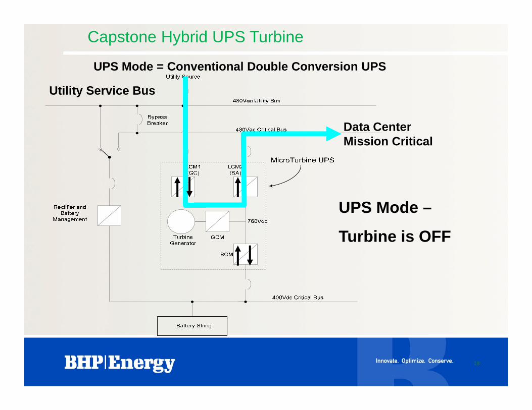
H t W tHot Water Production
using Turbine E h t H tExhaust Heat
Recovery(Integral HRM
shown in photo)

Turn Heat into ColdAbsorption Chiller
Hot Water Fired Direct Exhaust Fired
Chilled Chilled WaterWaterAbsorption Absorption
ChillerChillerHeat Heat
ExchangerExchangerAbsorption Absorption
ChillerChiller Chilled Chilled WaterWaterHot WaterHot Water
F lF l MicroturbineMicroturbine
Exhaust
ElectricityElectricityMi t biMi t bi
Hot WaterHot Water
FuelFuel ElectricityElectricityMicroturbineMicroturbineFuelFuel ElectricityElectricityMicroturbineMicroturbine

100 tonHot Water Fired (Single Effect)
Vapor Absorption p pTechnology

Direct Exhaust FiredDirect Exhaust FiredDouble Effect ChillerDouble Effect Chiller
5kW5kWWasteWaste
260kW Heat Rejection260kW Heat Rejection
100kW100kWChilled WaterChilled Water
Absorption Absorption ChillerChiller
65kW65kWEl t i itEl t i it
MicroturbineMicroturbine
160kW Exhaust160kW Exhaust
230kW230kWFuelFuel
ElectricityElectricity

Chilled Water (Double Effect)
Direct Exhaust Fired, Double Effect Vapor Absorption Technology

OperationOperation

Data Center Energy Use
PUE = 2 = Total PowerPUE = 2 = IT Equipment Power
27%
50%
Facility Cooling
Other
IT Equipment
23%
IT Equipment

Thermal Host• Green Data CenterGreen Data Center
– Essential Electric Power and CoolingNon Essential Loads– Non-Essential Loads
• Seek a “Thermal Host” opportunityf C– Part of or adjacent to Data Center
– Optimize turbine operation– Heating and Cooling Load– Electric Power Load

Optimize dispatch schedule using thermal hostOptimize dispatch schedule using thermal host
Direct Exhaust FiredDouble Effect Chiller
Optimize dispatch schedule using thermal hostOptimize dispatch schedule using thermal host
5kW5kWWasteWaste
260kW Heat Rejection260kW Heat Rejection
Double Effect Chiller
Th l H t
Cooling
100kW
100kW100kWChilled WaterChilled Water
Absorption Absorption ChillerChillerData Center
Thermal Host100kW
65kW65kWMicroturbineMicroturbine
160kW Exhaust160kW Exhaust
230kW230kWFuelFuel
65kW65kWElectricityElectricity

Multiple units optimize efficiency
30
35
20
25
y (%
)
15
Effic
ienc
y
Load Share Efficiency
5
10 Typical Turbine Efficiency
00 100 200 300 400 500 600 700 800 900 1000
Power (kW)
48

Capstone and LEED
Part 1: Sustainable SitesUp to 2 points
Part 3: Energy and AtmosphereUp to 10 pointsUp to 10 points
Part 4: Materials and ResourcesUp to 2 points
Part 5: Indoor Environmental QualityUp to 2 points
Part 6: Innovation and Design ProcessUp to 4 points

CertificationsCertificationsStandard Description Benefit
UL 2200 E i G t S t E dit B ildi A lUL 2200 Engine Generator Sets Expedites Building Approval (e.g. NYC)
UL 1741/IEEE 1547.1 Inverters for Utility Grid Simplifies UtilityyConnection
p yInterconnection (e.g. CA Rule 21, NY)
CARB California Air Resources Board DG Standard
Eliminates or simplifies air permittingBoard DG Standard permitting

Environmentally FriendlyEnvironmentally Friendly
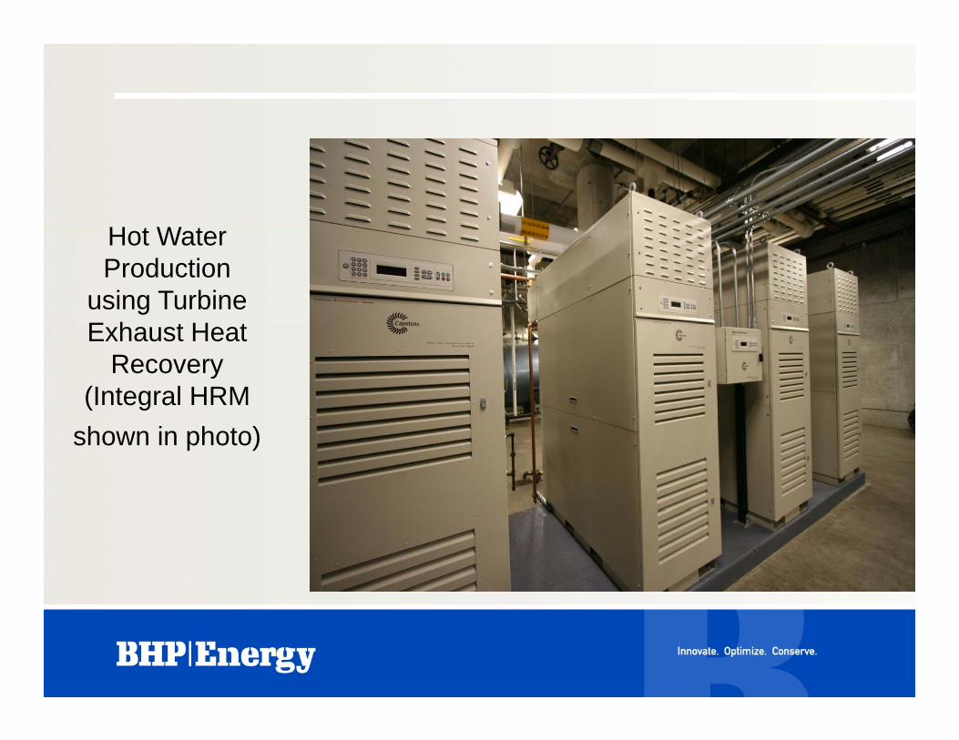
Emissions: Capstone C60‐ICHP vs. utility power & boiler
US EPA Data on Power Plant Emissions Pounds/MWh
0 771.2
1.5
O2
(tons
)
13.5
0.77
CO
13.5
0.026.0
SO2
ToledoNational av.C60 ICHP
3.45.3
NO
x
C60-ICHP
0.15
N
Source: US EPA and US DOE, see notes page for specific references, p g p

Environmentally Friendly
CO2 (lbs/MW) NOx (lbs/MWh)
2500
3000
4
5
6
NOx (lbs/MWh)
0
500
1000
1500
20002885
11350
1
2
3
46
0.15
Nox (lbs)
0
Traditional Green Data Center
61% Reduction 98% ReductionT diti l
Traditional Capstone Turbines
Traditional-Coal Power Plant-Centrifugal Chiller (5.44 COP)Source: EPA Power Profiler
ASHRAE 90.1 2004
Source: US EPA Environmental Technology Verification Test

Proof of Concept

Th G D tThe Green Data Center at Syracuse
University
IntroductionIntroduction– Syracuse University and IBM develop
advanced data centeradvanced data center– IBM contributes equipment and services
NYSERDA d f di– NYSERDA awards funding– Advanced Tech Integrator – BHP Energy
A hit t VIP St t– Architect – VIP Structures– E / M Engineer – Towne Engineering

Facility System Integration
G T bi (C t b d)• Gas Turbines (Capstone based)
– Inverter Based
– Super Clean Exhaust
99% U ti
ReliaFlex™
– > 99% Uptime
• Chilled Water Modules
– Exhaust Fired
H W M d l
Experience
• Hot Water Modules
– Domestic or building heating
• Control System
R M i i
Knowledge– Remote Monitoring
– BMS Interface
• Installation Services
ld Credibility– Design Build
– Single Source Responsibility
Credibility

ObjectivesObjectives– Reduce energy consumption by 50% (IBM)
A hi 60% b tt ffi i– Achieve 60% or better energy efficiency (NYSERDA)D l “b t ti ” it i i “ t– Develop “best practices” criteria, i.e. “system modeling”Integrate and demonstrate multiple– Integrate and demonstrate multiple technologies

Reduce Energy Use by 50%Reduce Energy Use by 50%– Recover energy expended to generate
electric power (CCHP)electric power (CCHP)– Use recovered energy not electricity for
cooling and heatingcooling and heating– Cool equipment directly with chilled water
rather than only cooling the room airrather than only cooling the room air– Use water side economizer and cooling
tower methodstower methods– Avoid power conversion loss

Key FeaturesKey Features– Tri-Generation (CCHP)
Ad d IBM t h l i– Advanced IBM technologies– “Patented” Capstone Hybrid UPS Turbine
AC and DC power distribution– AC and DC power distribution– Thermal Host– Cooling Tower / Water Side Heat Exchangerg g– Propane – Air Back-up Fuel– N+1 x 2 Redundancy– Battery System– Turbines replace traditional UPS

Three Features to ConsiderThree Features to Consider– Advanced Technology Integration– Operating Strategy– Mission Critical Innovation

Ad d T h l I t tiAdvanced Technology IntegrationIntegral Power Plant (CCHP)– Integral Power Plant (CCHP)
– Server Cooling TechnologiesAC and DC Power Distribution– AC and DC Power Distribution

Integral Power Plant (CCHP)
Electricity
Natural Gas
Heating
Cooling

Integral Power Plant (CCHP)

Energy recovery

Directly cooled servers

z196
Liquid Cooled Equipment
z196
p6 - 575
idataplex
19 inch rack serversrack servers

Thermal Imaging – Before and After

AC Power Distribution

DC Power Distribution

Operating Strategy– Turbine in Efficiency Mode (or Emergency
Mode if Grid Fails)– Optimize dispatch schedule
• Data Center PrimaryTh l h t S d• Thermal host Secondary
– Optimum Cooling W t id i• Water side economizer
• Cooling Tower Water when favorable• Exhaust heat driven chillerExhaust heat driven chiller
– Schedule reduced conversion loss

Optimize dispatch schedule Optimize dispatch schedule usingusing thermal hostthermal host
Direct Exhaust Fired
using using thermal hostthermal host
5kW5kW 260kW Heat Rejection260kW Heat Rejection
Double Effect ChillerCooling
WasteWaste
100kW100kWAbsorption Absorption
ChillerChillerData Center
Thermal Host100kW
100kW100kWChilled WaterChilled Water
160kW Exhaust160kW Exhaust
230kW230kWFuelFuel
65kW65kWElectricityElectricity
MicroturbineMicroturbine
Mission Critical Innovation
– Replace traditional UPS– Alternative Back-up SystemsAlternative Back up Systems
• Storage Battery• Utility Grid• Propane - Air
– “Patented” Capstone Hybrid UPS Turbine

Hybrid UPSHybrid UPSMainSwitch
Capstone “patented”
Hybrid UPS Turbines
Critical BusUtility Bus
Mission Non-Critical
Utilityy
Critical LoadLoad
Battery
• Standard UPS Mode with Turbines stopped
• Turbines operating in efficiency mode
• Turbines operating in emergency modeTurbines operating in emergency mode
• Upon loss of grid power, turbines auto start
• Mission Critical Load is powered at all times and isolated from grid disturbance

Tri Gen Strategy…on‐site produced power that is:
• Reliable
p p
Reliable
• Energy Efficient
O ti l• Operational
• Environmentally Friendly

Advanced Power SystemsAdvanced Power Systems
November 4, 2010 Rev 1