Embed Size (px)
Citation preview
Advanced Radioand Radar
Part 5Radar
IntroductionAs World War II approached,
scientists and the military were keen to find a method of detecting aircraft
outside the normal range of eyes and ears.
They found one, and at first called it
Radio Detection Finding (RDF), then changed it to
RAdio Detection And Ranging(RADAR).
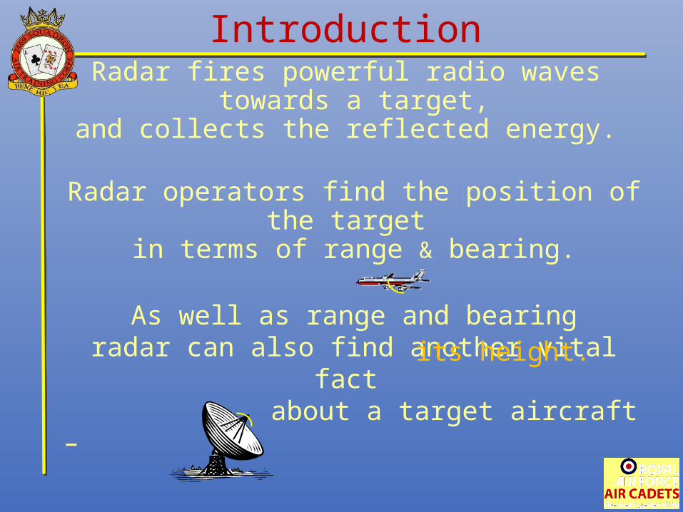
Radar fires powerful radio waves towards a target,
and collects the reflected energy.
Radar operators find the position of the target in terms of range & bearing.
As well as range and bearingradar can also find another vital fact
about a target aircraft –
Introduction
its height.
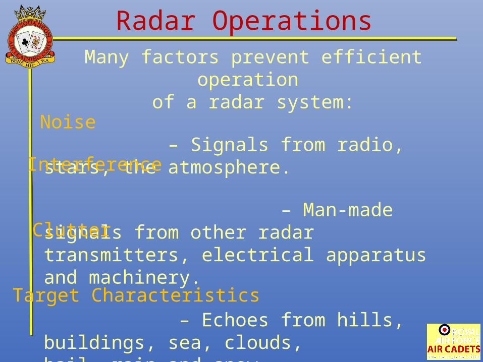
Radar OperationsMany factors prevent efficient operation
of a radar system:
– Signals from radio, stars, the atmosphere.
– Man-made signals from other radartransmitters, electrical apparatus and machinery.
– Echoes from hills, buildings, sea, clouds,hail, rain and snow.
– Shape and composition have an effect on its echo.
Noise
Interference
Clutter
Target Characteristics
Radar OperationsMany factors prevent efficient operation
of a radar system:
Noise
Interference
Clutter
Target Characteristics
Much of this can be reduced
by electronic techniques
Types of RadarThere are basically two different types of radar,
Primary and Secondary.
Primary Radar relies solely on the energy that it has generated and radiated,
being reflected back from the target – i.e. an echo.
Secondary Radar has some co-operation from the target –
the target generates its own ‘em’ radiation.
Primary RadarPrimary radar systems may be found in
ground, air, ship or space platforms, and are used in roles such as:
Surveillance (including weather)Early Warning
NavigationGround Mapping (from space or aircraft)
Guidance ControlTarget Detection and TrackingTerrain Following/Avoidance
Collision Avoidance and Altitude MeasurementAir Traffic Control
Primary RadarRadars operate in 2 different modes:
Pulse-Modulated Radar (pulsed)
and Continuous Wave Radar (CW).
They operate in the Ultra High Frequency (UHF) or Super High Frequency (SHF) bands.
This frequency depends on the radar function –
Long range search radaroperates on a relatively low frequency (UHF)
while a weapons system fire control radarwill operate at a very high frequency (SHF)
Primary Radar
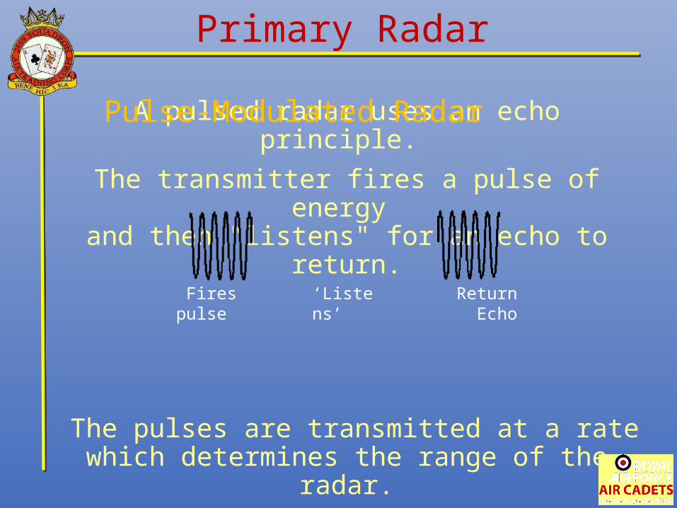
A pulsed radar uses an echo principle.
The transmitter fires a pulse of energy and then "listens" for an echo to return.
The pulses are transmitted at a rate which determines the range of the radar.
This is called the Pulse Repetition Frequency (PRF).
Fires pulse ‘Listens’ Return Echo
Pulse-Modulated Radar
Primary Radar
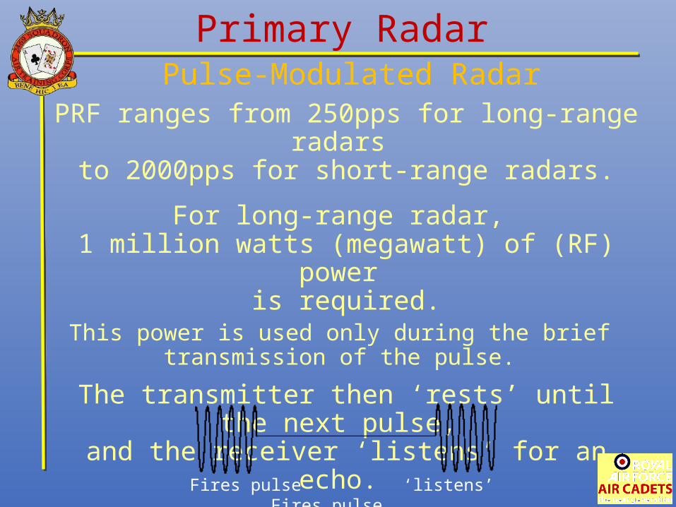
PRF ranges from 250pps for long-range radars to 2000pps for short-range radars.
For long-range radar, 1 million watts (megawatt) of (RF) power
is required.This power is used only during the brief
transmission of the pulse.
The transmitter then ‘rests’ until the next pulse, and the receiver ‘listens’ for an echo.
Fires pulse ‘listens’ Fires pulse
Pulse-Modulated Radar
Primary Radar
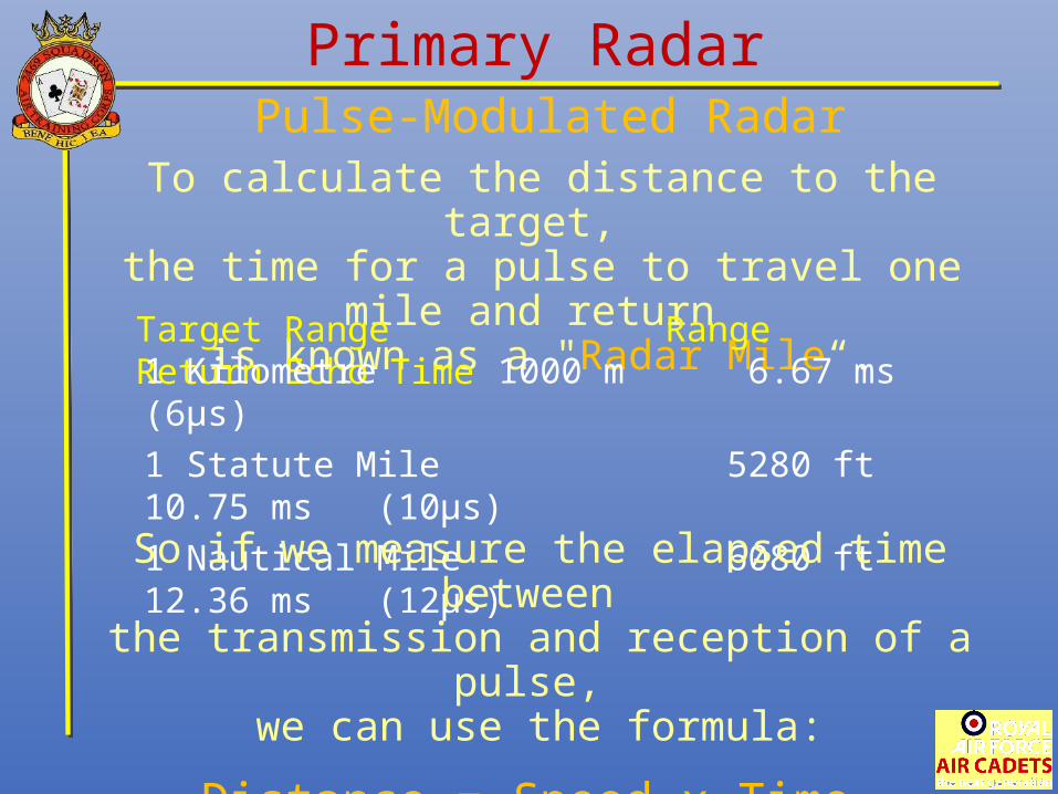
To calculate the distance to the target, the time for a pulse to travel one mile and return
is known as a "Radar Mile“.
Target Range Range Return Echo Time1 Kilometre 1000 m 6.67 ms (6μs)
1 Statute Mile 5280 ft 10.75 ms (10μs)
1 Nautical Mile 6080 ft 12.36 ms (12μs)
So if we measure the elapsed time between the transmission and reception of a pulse,
we can use the formula:
Distance = Speed x Time
Pulse-Modulated Radar
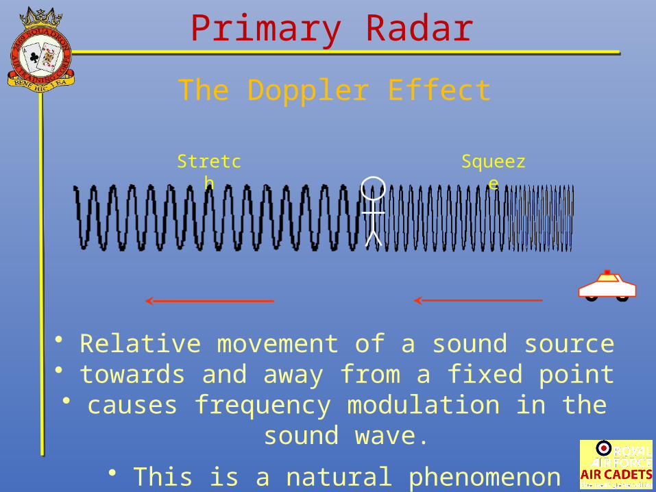
• Relative movement of a sound source • towards and away from a fixed point
• causes frequency modulation in the sound wave.
• This is a natural phenomenon
SqueezeStretch
Primary Radar
The Doppler Effect
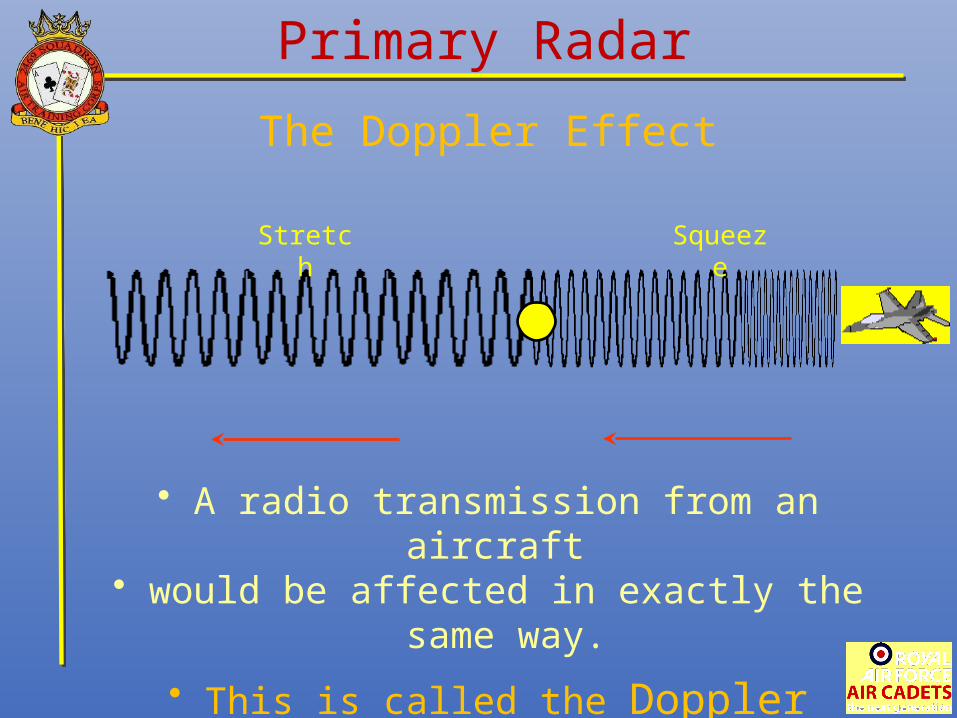
• A radio transmission from an aircraft • would be affected in exactly the same
way.
• This is called the Doppler Effect.
SqueezeStretch
Primary Radar
The Doppler Effect
Primary RadarContinuous Wave Radar (CW)
There are two basic types of CW radar.
Continuous Wave Doppler(CW Doppler)
and
Frequency-Modulated Continuous Wave(FMCW).
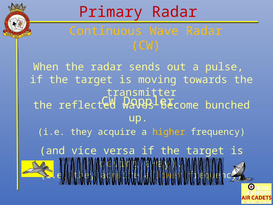
Primary RadarContinuous Wave Radar (CW)
When the radar sends out a pulse, if the target is moving towards the transmitter
the reflected waves become bunched up. (i.e. they acquire a higher frequency)
(and vice versa if the target is moving away).(i.e. they acquire a lower frequency)
CW Doppler
Primary RadarContinuous Wave Radar (CW)
The radar equipment is able to detect these small changes in frequency shifts
and so determine the target’s velocity(speed and direction)
with respect to the transmitter.
A similar system is used by traffic police with their "speed gun".
This is called the Doppler Effect.
CW Doppler
Frequency-Modulated CW Radar
is a short range measuring radarcapable of determining distance.
It is often used as a “radar altimeter” to measure the exact height
during the landing procedure of aircraft, and as early-warning radar,
and proximity sensors.
Primary RadarContinuous Wave Radar (CW)
Frequency-Modulated CW Radar
The signal is transmitted over a fixed band, and made to vary in frequency
in a controlled cyclic manner with respect to time.
By measuring the frequency of the returning echo it is possible to calculate the time interval elapsed
since that frequency was transmitted, and thus the target’s range.
Primary RadarContinuous Wave Radar (CW)
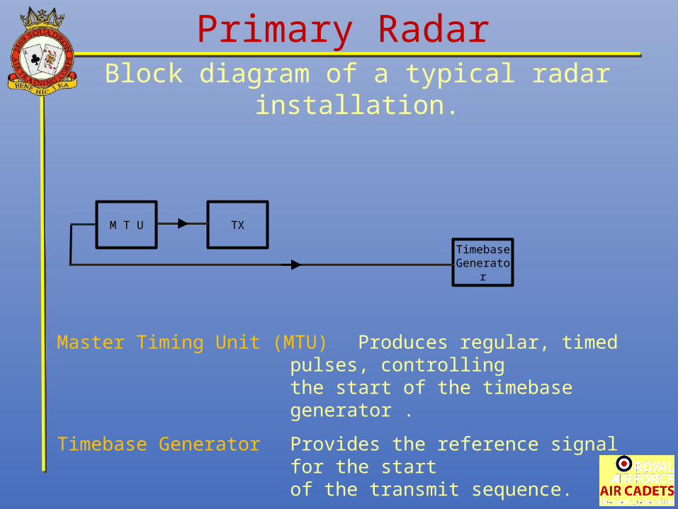
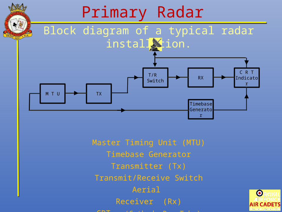
Primary RadarBlock diagram of a typical radar installation.
Master Timing Unit (MTU) Produces regular, timed pulses, controllingthe start of the timebase generator .
Timebase Generator Provides the reference signal for the start of the transmit sequence.
Transmitter (Tx) Produces high energy RF pulses in therange of 400 MHz to 40GHz.
TXM T U
TimebaseGenerator
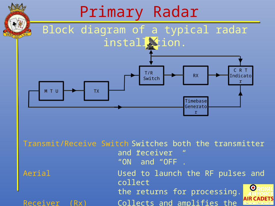
Primary RadarBlock diagram of a typical radar installation.
Transmit/Receive Switch Switches both the transmitter and receiver“ON” and “OFF”.
Aerial Used to launch the RF pulses and collectthe returns for processing.
Receiver (Rx) Collects and amplifies the returning echoesand produces video pulses to the display.
CRT (Cathode Ray Tube) Displays targets to the operator.
RXT/R
Switch
TXM T U
TimebaseGenerator
C R T Indicator
Primary RadarBlock diagram of a typical radar installation.
Master Timing Unit (MTU)
Timebase Generator
Transmitter (Tx)
Transmit/Receive Switch
Aerial
Receiver (Rx)
CRT (Cathode Ray Tube)
T/R Switch
TXM T U
RX
TimebaseGenerator
C R T Indicator
Secondary RadarIt is vital to know the identity of aircraft
displayed on an air traffic controller’s screen.
Identification Friend or Foe (IFF)is such a method.
Aircraft are fitted with a transmitter/receiver(transponder)
which resubmits a reply signal to an interrogating transmitter/receiver
(interrogator).
IFF equipment is specifically for military use, the civilian version is called SSR,
Secondary Surveillance Radar
Secondary RadarThe IFF/SSR systems can obtain
specific information from an aircraft.
The aircraft is interrogated on 1030 MHz using coded pulses or modes.
The aircraft responds on 1090 MHz using a standard system of codes.
There are 3 modes in use:
Mode 1 Military Aircraft Identify
Mode 2 Military Mission Identify
Mode 3 A) Common Military/Civilian Aircraft IdentifyB) Civil IdentifyC) Height Encoded Data
Secondary RadarIFF/SSR systems provide Air Traffic with
information about particular aircraft – far exceeding that of primary radar.
The types of information available are: Aircraft height
The aircraft can also send emergency information such as:
Loss of radio communications (code 7600)
Hijack (code 7500)
SOS (code 7700)
Direction,
Speed and Type of aircraft.(direct from aircraft’s altimeter)
Secondary RadarThe main advantages of
IFF/SSR over primary radar are:
a. No clutter problems (i.e. unwanted returns from rain clouds and mountains)
since transmitter and receiver operate on different frequencies.
b. Increased range with less transmitted power, as the radio waves only have to travel one way.
c. More information from each target.
d. Ability to use wide bandwidth receivers.
Check of UnderstandingWhat does RADAR stand for?
Radio direction and ranging
Ranging and direction radio
Ranging and detection radio
Radio detection and ranging

Check of UnderstandingRadar detects a target by calculating its . . .
Height, Range and Azimuth
Bearing, Height and Size
Height, Range and Velocity
Bearing, Height and Range

Check of UnderstandingIn this diagram
What does the block ‘T’ represent?
Rx Unit
Timebase Generator
Tx Unit
Master Timing Unit

A technique for minimising clutter in a radar system is:
Reduced by electronic techniques
Increased use of the PRF
Reduction of aerial scanning speed
Increased electronic countermeasures
Check of Understanding
What is the time used in rough calculations when working in Nautical miles?
10μs
1μs
6μs
Check of Understanding
12μs
Transmits waves which vary in frequency at a controlled rate
Is designed to detect targets at the longest possible range
Receives no co-operation from the target and relies upon reflection only
Utilises the change in frequency of reflected waves
Check of UnderstandingThe definition of a primary radar is one which:
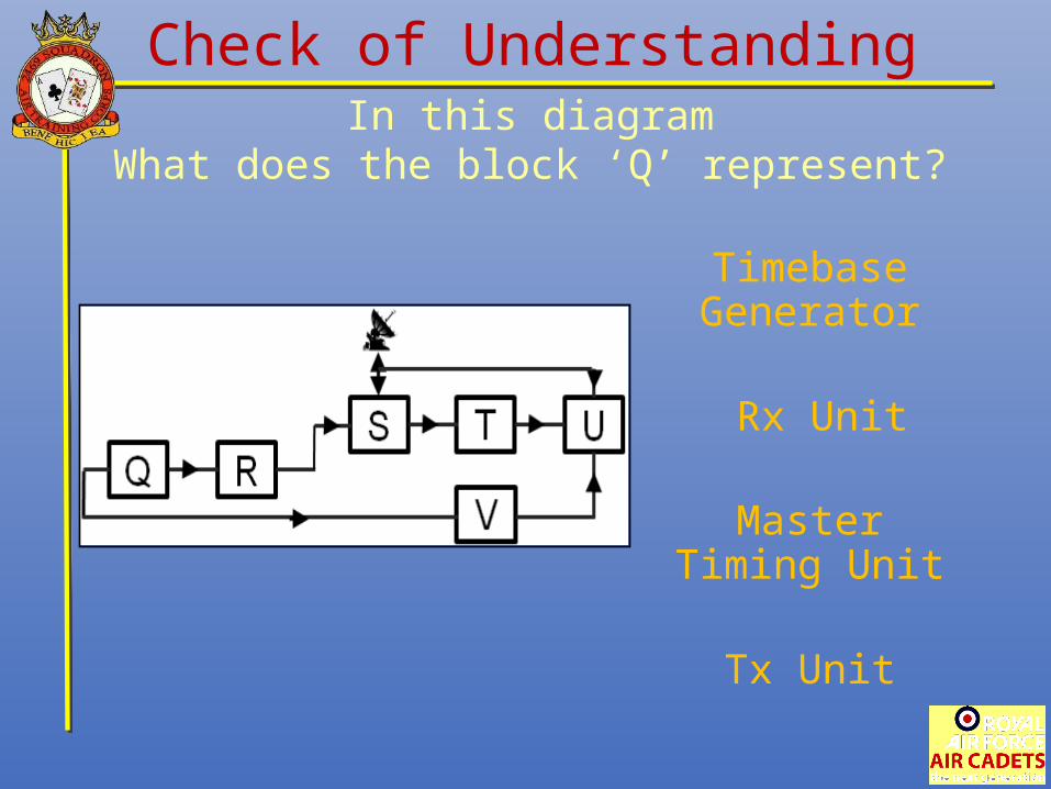
Check of UnderstandingIn this diagram
What does the block ‘Q’ represent?
Rx Unit
Timebase Generator
Tx Unit
Master Timing Unit
If a radar energy wave hits a target and returns with a frequency increase,
what effect is being used?
Pulsed Frequency
Demodulation
Frequency Modulation
Check of Understanding
Doppler
If the frequency of a reflected wave of a doppler radar decreases slightly,
What is the target doing?
Climbing towards the radar
Approaching
Descending towards the radar
Check of Understanding
Moving away
6μs
10μs
15μs
12μs
Check of UnderstandingWhat is the time unit
used in rough calculations when working in statue miles?

Tx Unit
Master Timing Unit
T/R Switch
Rx Unit
Check of UnderstandingIn this diagram
What does the block ‘S’ represent?
Check of UnderstandingThe unit in a secondary radar
which re-transmits the signals is called the . . .
Transmit-receive switch
Interrogator
Coding Unit
Transponder

Carrier Wave
Cyclic Wave
Continuous Wave
Inter-pulsed Wave
Check of UnderstandingWhich of the following
is a type of Primary Radar?
Speed of Target
Clutter
Height of Target
Frequency
Check of UnderstandingWhich of these factors
affects radar performance?

In this diagramWhat does the block ‘V’ represent?
CRT Indicator
Timebase Generator
Tx Unit
Rx Unit
Check of Understanding

What does SSR stand for?
Secondary surveillance radar
Single side radar
Single surveillance radar
Secondary side radar
Check of Understanding
Check of UnderstandingWhat is IFF used for?
Tells the pilot how many passengers are on board.
Alerts ATC of the direction of flight.
Tells other pilots your aircraft is airworthy.
Tells everyone you are friendly.
A pulse radar calculates the target rangeby using what?
Time between thetransmitted pulses
A pulse long enoughto reach the target
A pulse strong enough to reach the target
Check of Understanding
Time between transmission and receipt of the pulse

Tx Unit
Master Timing Unit
T/R Switch
Rx Unit
Check of UnderstandingIn this diagram
What does the block ‘R’ represent?
Check of UnderstandingSecondary Radar is defined as a system . . .
Where the target reflects the transmitted energy
Which operates when the primary radar fails
Where the target absorbs the transmitted energy
Where the target respondswith its own echo
What is the purpose of a timebase generator in a radar installation?
Used to launch the pulses and collect them on return
Synchronises the T/R Switch
Provides a reference signal for the receiver unit
Check of Understanding
Provides a reference signal to start the transmit sequence

A radar using doppler effectcalculates the targets velocity
by measuring what?
Frequency shift
Pulse return time
Return pulse length
Change of position
Check of Understanding
Which of these statements applies to an SSR receiver?
Single frequency
Multiband
Narrow bandwidth
Wide bandwidth
Check of Understanding

In this diagramWhat does the block ‘U’ represent?
CRT Indicator
Timebase Generator
Tx Unit
Rx Unit
Check of Understanding
Loss of radio Communication
SOS
Height
Highjack
Check of UnderstandingIn SSR usage,
what does the code 7700 mean?
What information is given out with Mode 3C in SSR?
Military identity
Height encoded data
Aircraft type
Civil identity
Check of Understanding
In a radar installation,what does the Master Timing Unit do?
Demodulates the frequency for the CDT display
Switches the timebase generator on and off
Produces pulses at the required level to drive the aerial
Check of Understanding
Controls the start of the transmitter and the timebase generator
Advanced Radioand Radar
End of Presentation