Embed Size (px)
Citation preview
ADVANCED SUBSIDIARY (AS)General Certifi cate of Education
2019
Time1 hour, plus your additional time allowance.
Instructions to CandidatesWrite your Centre Number and Candidate Number in the spaces provided at the top of this page.Answer both questions in either Section A , B or C.
Information for CandidatesThe total mark for this paper is 40.
Figures in brackets printed at the end of each question indicate the marks awarded to each question or part question.
Technology and DesignAssessment Unit AS 1
assessingSystems and Control or
Product Design
[STE12]THURSDAY 16 MAY, AFTERNOON
11858.04 MV18
Centre Number
Candidate Number
MV18
Section A
Electronic and Microelectronic Control Systems
Answer both questions in this section.
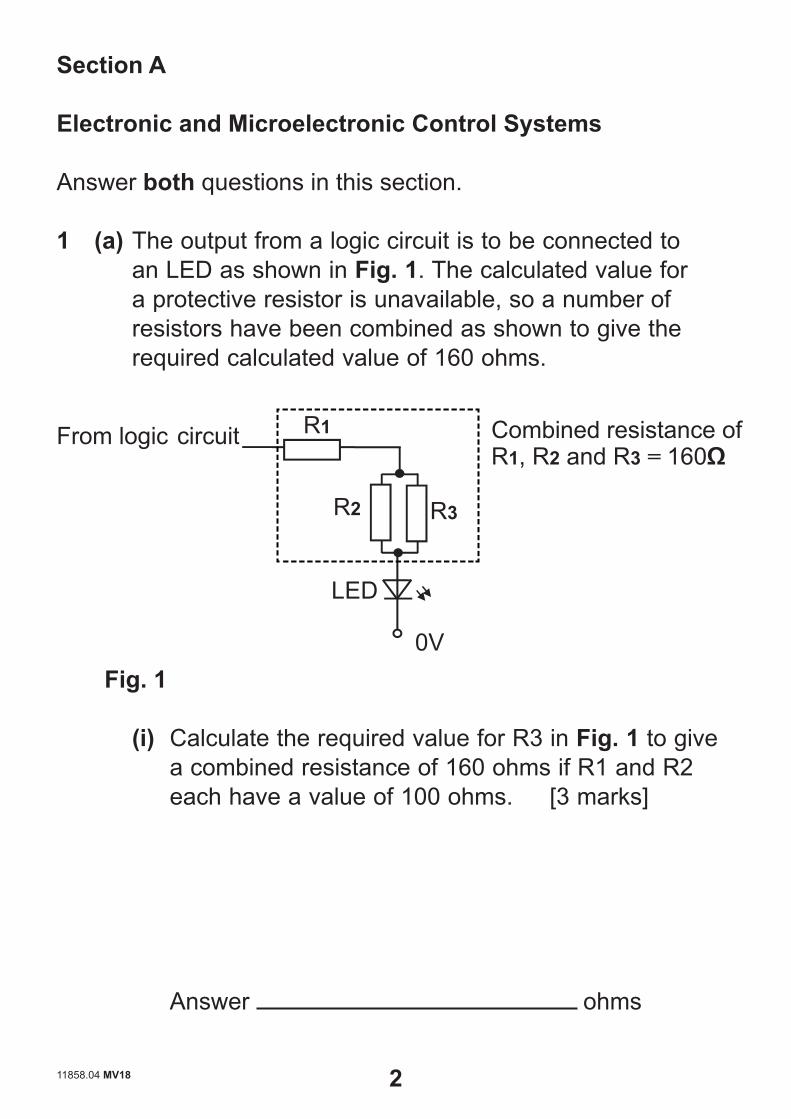
1 (a) The output from a logic circuit is to be connected to an LED as shown in Fig. 1. The calculated value for a protective resistor is unavailable, so a number of resistors have been combined as shown to give the required calculated value of 160 ohms.
From logic circuit
LED
0V
R1
R2 R3
Combined resistance of R1, R2 and R3 = 160Ω
Fig. 1
(i) Calculate the required value for R3 in Fig. 1 to give a combined resistance of 160 ohms if R1 and R2 each have a value of 100 ohms. [3 marks]
Answer ohms
11858.04 MV18 2 [Turn over

(ii) Calculate the total maximum power in mW that could be dissipated by the resistors R1, R2 and R3 in Fig. 1
if the LED operates at a forward voltage of 2 volts. Assume the voltage from the logic circuit is 6V, the combined resistance of R1, R2 and R3 is 160 ohms and they each have a stated tolerance of +/– 10%.
[3 marks]
Answer mW
11858.04 MV18 3 [Turn over
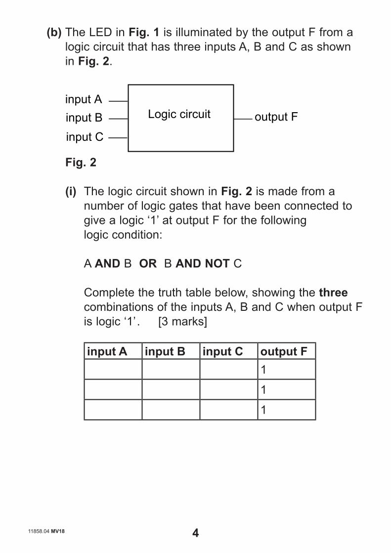
(b) The LED in Fig. 1 is illuminated by the output F from a logic circuit that has three inputs A, B and C as shown in Fig. 2.
input A input B input C
Logic circuit output F
Fig. 2
(i) The logic circuit shown in Fig. 2 is made from a number of logic gates that have been connected to give a logic ‘1’ at output F for the following
logic condition:
A AND B OR B AND NOT C
Complete the truth table below, showing the three combinations of the inputs A, B and C when output F is logic ‘1’ . [3 marks]
input A input B input C output F
1
1
1
11858.04 MV18 4 [Turn over

(ii) Using the appropriate gate symbols, draw a logic circuit to fulfil the logic condition stated in part (b)(i).
[3 marks]
(iii) The input to a logic circuit consists of a SPDT micro
switch and a resistor. Complete the circuit diagram in Fig. 3 below to enable a logic ‘1’ at the input when the micro switch is moved to terminal 3 and a
‘logic 0’ when moved to terminal 2. [2 marks]
1
6V
0V
input SPDT micro switch
2 3
Logic circuit
Fig. 3
11858.04 MV18 5 [Turn over
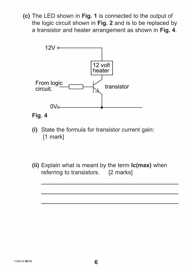
(c) The LED shown in Fig. 1 is connected to the output of the logic circuit shown in Fig. 2 and is to be replaced by a transistor and heater arrangement as shown in Fig. 4.
12 volt heater
12V
0V
From logic circuit. transistor
Fig. 4
(i) State the formula for transistor current gain: [1 mark]
(ii) Explain what is meant by the term Ic(max) when referring to transistors. [2 marks]
11858.04 MV18 6 [Turn over

(iii) If the resistance of the heater shown in Fig. 4 is 25 ohms and the transistor base current is 2mA, calculate the gain required for the transistor and choose an appropriate transistor from one of the
four types shown in the table in Fig. 5. [2 marks for gain, 1 mark for transistor]
Transistor lc(max) hfeType A 1.2A 100Type B 600mA 200Type C 500mA 300Type D 400mA 400
Fig. 5
Gain required =
Chosen transistor type =
11858.04 MV18 7 [Turn over
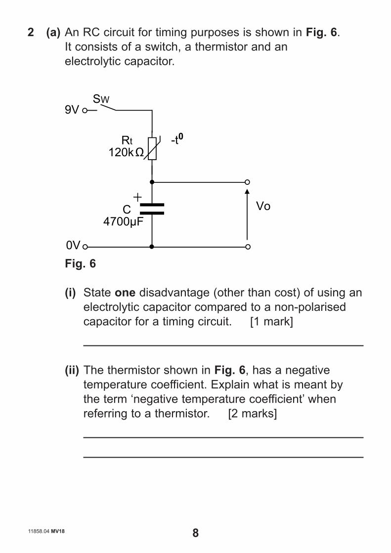
2 (a) An RC circuit for timing purposes is shown in Fig. 6. It consists of a switch, a thermistor and an electrolytic capacitor.
SW 9V
Rt120kΩ
-t0
C 4700μF
Vo
0V Fig. 6
(i) State one disadvantage (other than cost) of using an electrolytic capacitor compared to a non-polarised capacitor for a timing circuit. [1 mark]
(ii) The thermistor shown in Fig. 6, has a negative temperature coefficient. Explain what is meant by the term ‘negative temperature coefficient’ when referring to a thermistor. [2 marks]
11858.04 MV18 8 [Turn over
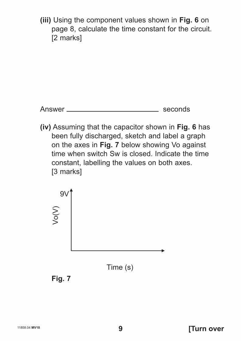
(iii) Using the component values shown in Fig. 6 on page 8, calculate the time constant for the circuit.
[2 marks]
Answer seconds
(iv) Assuming that the capacitor shown in Fig. 6 has been fully discharged, sketch and label a graph on the axes in Fig. 7 below showing Vo against time when switch Sw is closed. Indicate the time constant, labelling the values on both axes.[3 marks]
Vo(
V)
Time (s)
9V
Fig. 7
11858.04 MV18 9 [Turn over
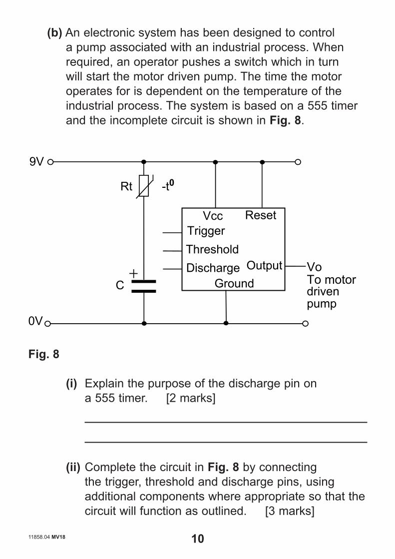
(b) An electronic system has been designed to control a pump associated with an industrial process. When required, an operator pushes a switch which in turn will start the motor driven pump. The time the motor operates for is dependent on the temperature of the industrial process. The system is based on a 555 timer and the incomplete circuit is shown in Fig. 8.
-t0Rt
Vcc
DischargeThreshold Trigger
Ground
Reset
Output C
0V
9V
Vo To motor driven pump
Fig. 8
(i) Explain the purpose of the discharge pin on a 555 timer. [2 marks]
(ii) Complete the circuit in Fig. 8 by connecting the trigger, threshold and discharge pins, using additional components where appropriate so that the circuit will function as outlined. [3 marks]
11858.04 MV18 10 [Turn over
(iii) Calculate the resistance of the thermistor Rt in Fig. 8 if the time period of the output Vo is 7.48 seconds and the value of C is 100μF. Assume the circuit is complete. [3 marks]
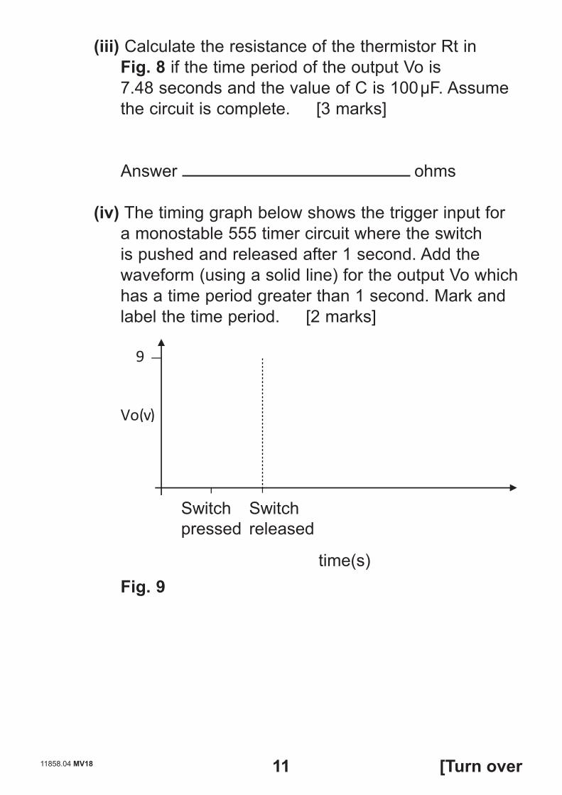
Answer ohms (iv) The timing graph below shows the trigger input for
a monostable 555 timer circuit where the switch is pushed and released after 1 second. Add the waveform (using a solid line) for the output Vo which has a time period greater than 1 second. Mark and label the time period. [2 marks]
Switch released
Vo (v)
9
time(s)
Switchpressed
Fig. 9
11858.04 MV18 11 [Turn over
(v) State one safety issue to consider when testing low voltage electronic systems in an educational environment and suggest one procedure that could be implemented to prevent injury associated with
the issue. [1 mark for each]
Safety issue
Procedure
11858.04 MV18 12 [Turn over

Blank Page
(Questions continue overleaf)
11858.04 MV18 13 [Turn over

Section B
Mechanical and Pneumatic Control Systems
Answer both questions in this section.
3 Fig. 10 shows an incomplete conveyor belt system which incorporates both mechanical and pneumatic components. Packages activate the air bleed as they move past on the conveyor belt.
Pulley W
Motor
Conveyor Belt
Air Bleed
Pulley Q Not to Scale
Package
A
Fig. 10
11858.04 MV18 14 [Turn over

(a) Name the activation method at three port valve A. [1 mark]
(b) To prevent slipping, the belt connecting Pulley Q and Pulley W is to be fitted with a self-adjusting jockey wheel. Using an annotated sketch, draw the main features of this mechanical component. [3 marks]
11858.04 MV18 15 [Turn over

(c) Valve A, shown in Fig. 10 on page 14, forms part of the incomplete pneumatic circuit shown in Fig. 11. Add any necessary additional components to Fig. 11 to enable speed control of the outstroke of the double acting cylinder following a delay in time after valve A has been activated. [4 marks]
12
5 3
4 2
1
14 A
B C
E D
Fig. 11
(d) Add any necessary additional components to Fig. 11 to enable the double acting cylinder to instroke following activations at B OR C OR D AND NOT E. [5 marks]
11858.04 MV18 16 [Turn over

(e) Pulley W, shown in Fig. 10, is attached to the motor shaft using a key and keyway. Using an annotated sketch, show the main features of this fixing method.
[3 marks]
(f) The double acting cylinder, shown in Fig. 11, operates with an air pressure of 0.5 N/mm2, produces a force of 100N during the outstroke and a force of 74.88N during the instroke. Calculate the piston rod radius. Please assume π = 3.14. [4 marks]
Answer mm 11858.04 MV18 17 [Turn over
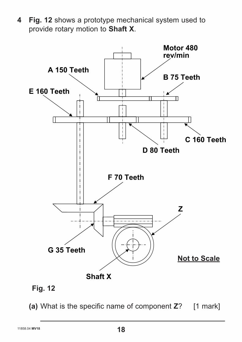
4 Fig. 12 shows a prototype mechanical system used to provide rotary motion to Shaft X.
Shaft X
C 160 Teeth D 80 Teeth
E 160 Teeth
Motor 480 rev/min
F 70 Teeth
G 35 Teeth
B 75 Teeth A 150 Teeth
Z
Fig. 12
(a) What is the specific name of component Z? [1 mark]
Not to Scale
11858.04 MV18 18 [Turn over
(b) Calculate the velocity ratio between A and G.[4 marks]
Answer
(c) Calculate the number of teeth required on Z to enable it to rotate at 8 rev/min if E rotates at 144 rev/min.[3 marks]
Answer
11858.04 MV18 19 [Turn over
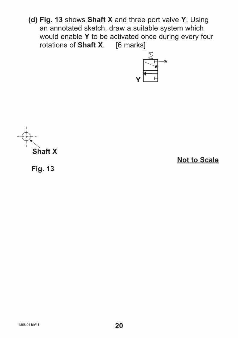
(d) Fig. 13 shows Shaft X and three port valve Y. Using an annotated sketch, draw a suitable system which would enable Y to be activated once during every four rotations of Shaft X. [6 marks]
Shaft X
Y
Not to Scale Fig. 13
11858.04 MV18 20 [Turn over

(e) Fig. 14 shows an incomplete pneumatic circuit incorporating valve Y as shown in Fig. 13. Complete the pneumatic circuit to enable both cylinders T and U to outstroke following an activation at Y. When Y is not activated, the cylinders should return to their instroke positions. Please note that no further three or five port valves are available for use. [6 marks]
2 4 14
15 3
Y
Cylinder T
Cylinder U
Fig. 14
11858.04 MV18 21 [Turn over

Section C
Product Design
Answer both questions in this section.
5 Fig. 15 below shows the dilemma that many city cyclists face as they attempt to explore their surroundings whilst consuming a cup of coffee on the go. A handlebar coffee cup holder that is easy to install and use could provide the cyclist with a possible solution.
Fig. 15
(a) When generating ideas for a handlebar coffee cup holder, designers employed the technique of thought showers.
State two specific characteristics associated with thought showers. [2 marks]
1.
2.
11858.04 MV18 22 [Turn over
(b) One concept that emerged from the thought showers was the idea to produce a holder manufactured from carbon fibre reinforced plastic (CFRP).
(i) State two specific properties associated with CFRP which would make it suitable for the holder.
[2 marks]
1.
2.
(ii) State one main specific reason why CFRP may not
be a suitable material for the holder. [1 mark]
(c) When producing the coffee cup holder, employee and consumer safety had to be given careful consideration.
Distinguish between employee and consumer safety. [2 marks]
11858.04 MV18 23 [Turn over

11858.04 MV18 24 [Turn over
(d) The handlebar coffee cup holders are to be mass-produced.
Briefly outline two main characteristics associated with mass production. [2 marks]
1.
2.
(e) After discussing the intellectual property rights of the
new design for the handlebar coffee cup holder, the design team decided to apply for a registered design.
Briefly outline three different characteristics associated with a registered design. [3 marks]
1.
2.
3.

Blank Page
(Questions continue overleaf)
11858.04 MV18 25 [Turn over
11858.04 MV18 26 [Turn over
(f) An important part of the design process for any company is to undertake a product review.
Explain what is meant by a product review. [2 marks]
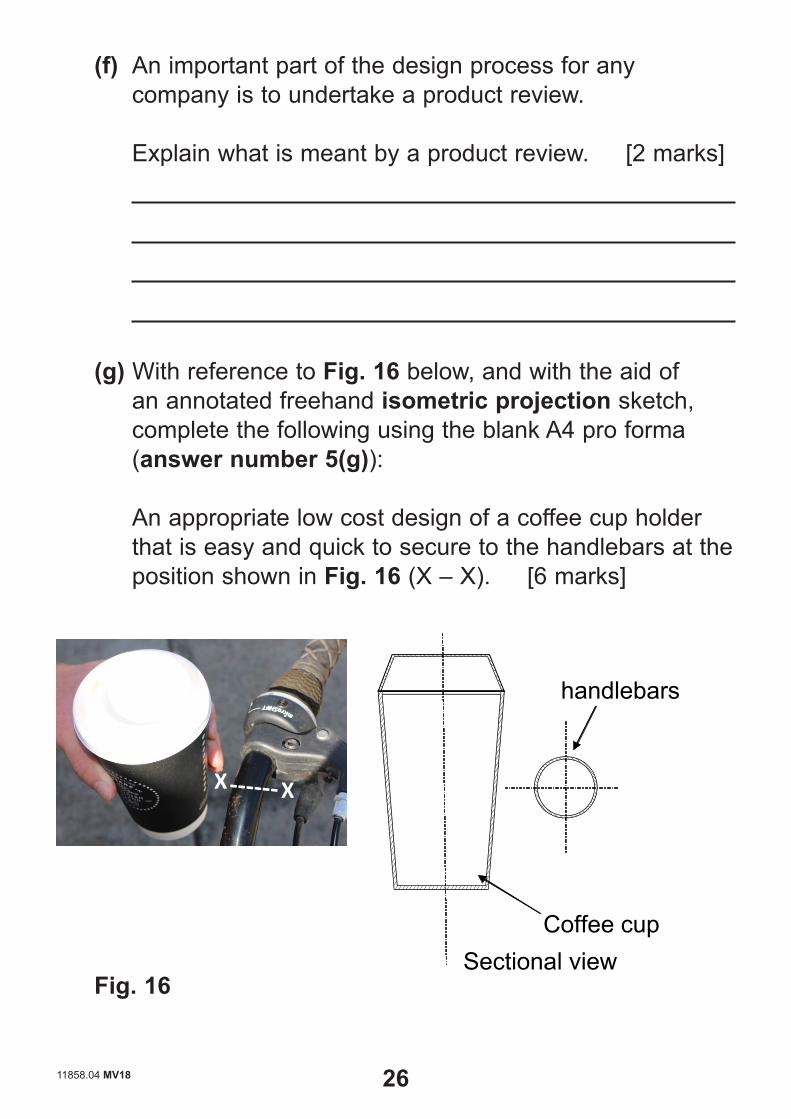
(g) With reference to Fig. 16 below, and with the aid of an annotated freehand isometric projection sketch, complete the following using the blank A4 pro forma (answer number 5(g)):
An appropriate low cost design of a coffee cup holder that is easy and quick to secure to the handlebars at the position shown in Fig. 16 (X – X). [6 marks]
X
handlebars
Coffee cupSectional view
X X
Fig. 16

11858.04 MV18 27 [Turn over
A4
pro
form
a an
swer
pag
e (a
nsw
er n
umbe
r 5(g
))
11858.04 MV18 28 [Turn over
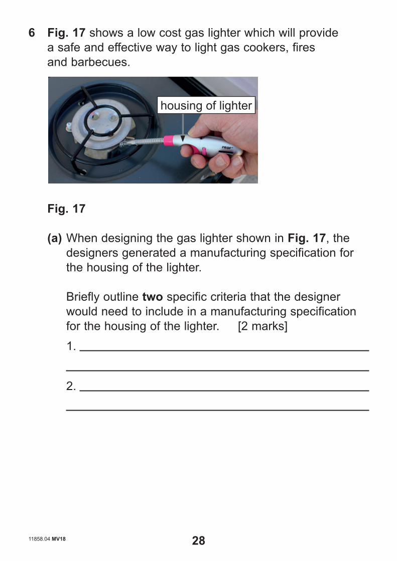
6 Fig. 17 shows a low cost gas lighter which will provide a safe and effective way to light gas cookers, fires and barbecues.
housing of lighter
Fig. 17
(a) When designing the gas lighter shown in Fig. 17, the designers generated a manufacturing specification for the housing of the lighter.
Briefly outline two specific criteria that the designer would need to include in a manufacturing specification for the housing of the lighter. [2 marks]
1.
2.

11858.04 MV18 29 [Turn over
(b) A 2D model of the gas lighter is to be laser cut from acrylic. With the use of an annotated sketch, explain the process of laser cutting which could be used to cut the model of the gas lighter. [5 marks]
(c) Prior to production of the gas lighter, a work order was created. Briefly outline what is meant by a work order.
[1 mark]
(d) When producing the gas lighter, the requirements of the Trade Descriptions Act had to be considered.
Briefly outline two main requirements of the Trade Descriptions Act that the gas lighter company would need to comply with when deciding upon the information for the packaging. [2 marks]
1.
2.
11858.04 MV18 30 [Turn over
(e) It may be argued that the design of the gas lighter shown in Fig. 17 has not been influenced by cultural or social change to the same extent as many other specific products.
(i) With reference to a suitable specific product of your
choice, outline one main social change and explain what influence this has had on its design.
Social change [1 mark]
Explanation [2 marks]
(ii) With reference to a suitable specific product of your choice, outline one main cultural change and explain what influence this has had on its design.
Cultural change [1 mark]
Explanation [2 marks]

11858.04 MV18 31 [Turn over
Blank Page
(Questions continue overleaf)
11858.04 MV18 32 [Turn over
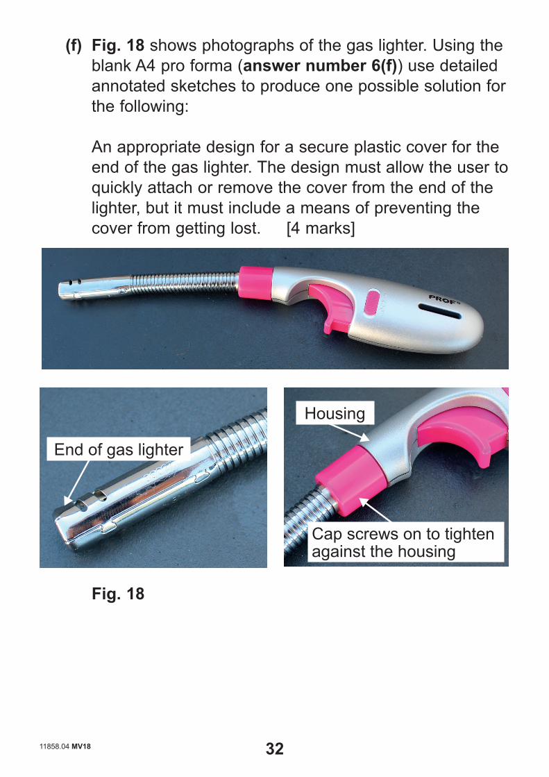
(f) Fig. 18 shows photographs of the gas lighter. Using the blank A4 pro forma (answer number 6(f)) use detailed annotated sketches to produce one possible solution for the following:
An appropriate design for a secure plastic cover for the end of the gas lighter. The design must allow the user to quickly attach or remove the cover from the end of the lighter, but it must include a means of preventing the cover from getting lost. [4 marks]
Fig. 18
End of gas lighter
Housing
Cap screws on to tighten against the housing

11858.04 MV18 33
A4
pro
form
a an
swer
pag
e (a
nsw
er n
umbe
r 6(f)
)

This is the end of the question paper


11858.04 MV18
Permission to reproduce all copyright material has been applied for.In some cases, efforts to contact copyright holders may have been unsuccessful and CCEAwill be happy to rectify any omissions of acknowledgement in future if notifi ed.
For Examiner’s use only
Question Number Marks
123456
Total Marks
SOURCES:Q1(a) .....Source: CCEAQ1(b) .....Source: CCEAQ1(c) ......Source: CCEAQ2(a) .....Source: CCEAQ2(a)(iv) Source: CCEAQ2(b) .....Source: CCEAQ5 ..........Source: Principal ExaminerQ5(g) .....Source: Principal ExaminerQ6 ..........Source: Principal ExaminerQ6(f) ......Source: Principal Examiner
1st proof 5/4/19 GS