Embed Size (px)
Citation preview

2AEXTREMELY BROADBAND
OMNIS
A) VERTICALLY POLARIZED, RECEIVE ONLY
Our SAS series antennas are ideally suited for spectrum surveillance and spectrum management applications. These are extremely broadband, portable receive antennas designed specifically for accurate measurement of the vertical electric field intensity. Integral active networks provide outstanding performance over the entire frequency range of operation. This is performance normally associated with full-scale antennas many times larger. All SAS series antennas except for SAS-2 alpha antennas are supplied with protective radomes for outdoor use.
SAS-2 and SAS-2/SE antennas are designed for use in environmentally controlled chambers or test laboratories. The SAS-2 series antennas have an integrated, rechargeable power supply for stand -alone operation.
A gradual roll-off in the response below 10 kHz in SAS antennas prevents overload due to strong 60 Hz harmonics, in areas where man-made noise is a problem. Some SAS antennas can be modified for significantly larger overload protection when used in a high field environment (see available options for SAS-220).
SAS-230 series antennas covering 20 MHz to 3 GHz are available with high and low band preamplifiers which maybe bypassed remotely by integrated low loss coax switches. See separate datasheet for more details related to various options available for the SAS-230 antenna.
Remote and rack-mountable power supplies are also available for use with SAS antennas. These antennas can be modified for use with auto batteries for vehicle mounted applications.
SAS-11/E
SAS-220 ON A VEHICLE
SAS-220/CR in a mobile Spectrum Management System
Telephone Fax 1-301-937-8888 1-301-937-2796 (MD)1-877-ARA-SALE 1-781-829-4590 (MA) [email protected]
1 WWW.ARA-INC.COM
Advanced Test Equipment Rentalswww.atecorp.com 800-404-ATEC (2832)
®
Established 1981
Telephone Fax 1-301-937-8888 1-301-937-2796 (MD) [email protected] 1-877-ARA-SALE 1-781-829-4590 (MA)
2
2A EXTREMELY BROADBAND OMNIS
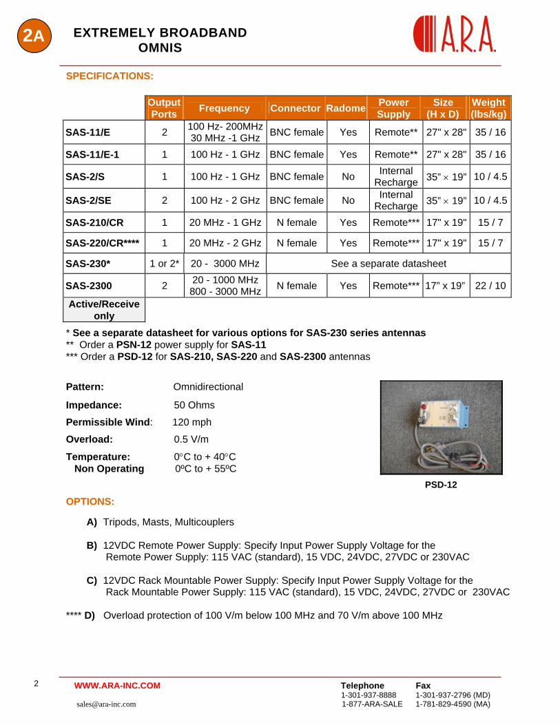
SPECIFICATIONS:
Output Ports Frequency Connector Radome Power
Supply Size
(H x D) Weight (lbs/kg)
SAS-11/E 2 100 Hz- 200MHz30 MHz -1 GHz BNC female Yes Remote** 27" x 28" 35 / 16
SAS-11/E-1 1 100 Hz - 1 GHz BNC female Yes Remote** 27" x 28" 35 / 16
SAS-2/S 1 100 Hz - 1 GHz BNC female No Internal Recharge 35” × 19” 10 / 4.5
SAS-2/SE 2 100 Hz - 2 GHz BNC female No Internal Recharge 35” × 19” 10 / 4.5
SAS-210/CR 1 20 MHz - 1 GHz N female Yes Remote*** 17" x 19" 15 / 7
SAS-220/CR**** 1 20 MHz - 2 GHz N female Yes Remote*** 17" x 19" 15 / 7
SAS-230* 1 or 2* 20 - 3000 MHz See a separate datasheet
SAS-2300 2 20 - 1000 MHz 800 - 3000 MHz N female Yes Remote*** 17” x 19” 22 / 10
Active/Receive only
* See a separate datasheet for various options for SAS-230 series antennas ** Order a PSN-12 power supply for SAS-11 *** Order a PSD-12 for SAS-210, SAS-220 and SAS-2300 antennas
Pattern: Omnidirectional
Impedance: 50 Ohms
Permissible Wind: 120 mph
Overload: 0.5 V/m
Temperature: 0°C to + 40°C Non Operating 0ºC to + 55ºC
PSD-12
OPTIONS:
A) Tripods, Masts, Multicouplers
B) 12VDC Remote Power Supply: Specify Input Power Supply Voltage for the Remote Power Supply: 115 VAC (standard), 15 VDC, 24VDC, 27VDC or 230VAC
C) 12VDC Rack Mountable Power Supply: Specify Input Power Supply Voltage for the Rack Mountable Power Supply: 115 VAC (standard), 15 VDC, 24VDC, 27VDC or 230VAC
**** D) Overload protection of 100 V/m below 100 MHz and 70 V/m above 100 MHz
WWW.ARA-INC.COM
2AEXTREMELY BROADBAND
OMNIS
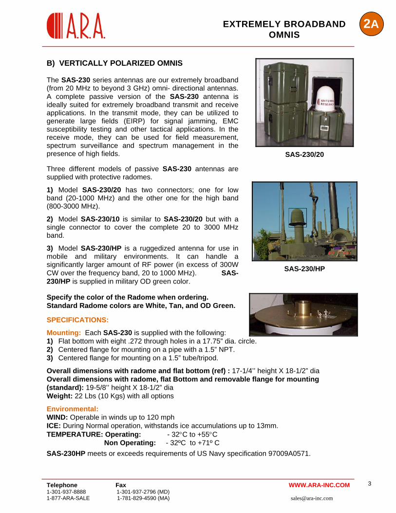
B) VERTICALLY POLARIZED OMNIS The SAS-230 series antennas are our extremely broadband (from 20 MHz to beyond 3 GHz) omni- directional antennas. A complete passive version of the SAS-230 antenna is ideally suited for extremely broadband transmit and receive applications. In the transmit mode, they can be utilized to generate large fields (EIRP) for signal jamming, EMC susceptibility testing and other tactical applications. In the receive mode, they can be used for field measurement, spectrum surveillance and spectrum management in the presence of high fields. Three different models of passive SAS-230 antennas are supplied with protective radomes.
1) Model SAS-230/20 has two connectors; one for low band (20-1000 MHz) and the other one for the high band (800-3000 MHz).
2) Model SAS-230/10 is similar to SAS-230/20 but with a single connector to cover the complete 20 to 3000 MHz band.
3) Model SAS-230/HP is a ruggedized antenna for use in mobile and military environments. It can handle a significantly larger amount of RF power (in excess of 300W CW over the frequency band, 20 to 1000 MHz). SAS-230/HP is supplied in military OD green color.
SAS-230/20
SAS-230/HP
Specify the color of the Radome when ordering.
Telephone Fax 1-301-937-8888 1-301-937-2796 (MD) 1-877-ARA-SALE 1-781-829-4590 (MA) [email protected]
3 WWW.ARA-INC.COM
Standard Radome colors are White, Tan, and OD Green. SPECIFICATIONS:
Mounting: Each SAS-230 is supplied with the following: 1) Flat bottom with eight .272 through holes in a 17.75” dia. circle. 2) Centered flange for mounting on a pipe with a 1.5” NPT. 3) Centered flange for mounting on a 1.5” tube/tripod.
Overall dimensions with radome and flat bottom (ref) : 17-1/4’’ height X 18-1/2” dia Overall dimensions with radome, flat Bottom and removable flange for mounting (standard): 19-5/8’’ height X 18-1/2” dia Weight: 22 Lbs (10 Kgs) with all options
Environmental: WIND: Operable in winds up to 120 mph ICE: During Normal operation, withstands ice accumulations up to 13mm. TEMPERATURE: Operating: - 32°C to +55°C Non Operating: - 32ºC to +71º C
SAS-230HP meets or exceeds requirements of US Navy specification 97009A0571.
Telephone Fax 1-301-937-8888 1-301-937-2796 (MD) [email protected] 1-877-ARA-SALE 1-781-829-4590 (MA)
4
2A EXTREMELY BROADBAND OMNIS
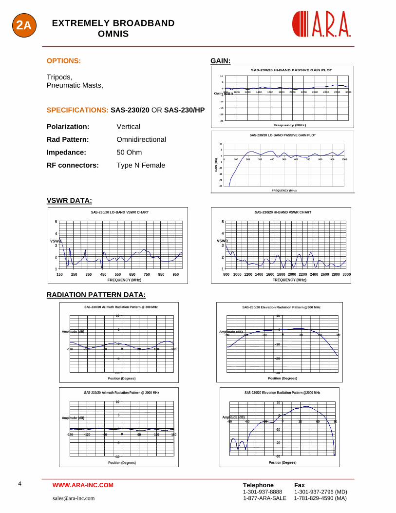
GAIN:
SAS-230/20 HI-BAND PASSIVE GAIN PLOT
-25
-20
-15
-10
-5
0
5
10
800 1000 1200 1400 1600 1800 2000 2200 2400 2600 2800 3000
Frequency (MHz
Gain (dBi)
)
OPTIONS: Tripods, Pneumatic Masts, SPECIFICATIONS: SAS-230/20 OR SAS-230/HP Polarization: Vertical
Rad Pattern: Omnidirectional
Impedance: 50 Ohm
RF connectors: Type N Female
SAS-230/20 LO-BAND PASSIVE GAIN PLOT
-25
-20
-15
-10
-5
0
5
10
0 100 200 300 400 500 600 700 800 900 1000
FREQUENCY (MHz)
GA
IN (d
Bi)
VSWR DATA:
SAS-230/20 HI-BAND VSWR CHART
1
2
3
4
5
800 1000 1200 1400 1600 1800 2000 2200 2400 2600 2800 3000FREQUENCY (MHz)
VSWR
SAS-230/20 LO-BAND VSWR CHART
1
2
3
4
5
150 250 350 450 550 650 750 850 950FREQUENCY (MHz)
VSWR
RADIATION PATTERN DATA:
SAS-230/20 Azimuth Radiation Pattern @ 300 MHz
-10
-5
0
5
10
-180 -120 -60 0 60 120 180
Position (Degrees)
Amplitude (dB)
SAS-230/20 Elevation Radiation Pattern @300 MHz
-30
-20
-10
0
10
-90 -60 -30 0 30 60 90
Position (Degrees)
Amplitude (dB)
SAS-230/20 Azimuth Radiation Pattern @ 2000 MHz
-10
-5
0
5
10
-180 -120 -60 0 60 120 180
Position (Degrees)
Amplitude (dB)
SAS-230/20 Elevation Radiation Pattern @2000 MHz
-30
-20
-10
0
10
-90 -60 -30 0 30 60 90
Position (Degrees)
Amplitude (dB)
WWW.ARA-INC.COM
2AEXTREMELY BROADBAND
OMNIS
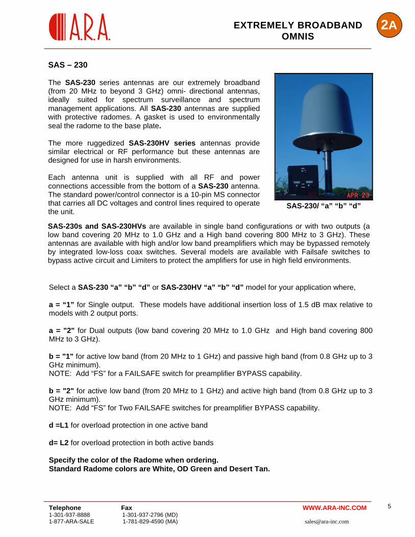
SAS-230s and SAS-230HVs are available in single band configurations or with two outputs (a low band covering 20 MHz to 1.0 GHz and a High band covering 800 MHz to 3 GHz). These antennas are available with high and/or low band preamplifiers which may be bypassed remotely by integrated low-loss coax switches. Several models are available with Failsafe switches to bypass active circuit and Limiters to protect the amplifiers for use in high field environments.
SAS-230/ “a” “b” “d”
SAS – 230 The SAS-230 series antennas are our extremely broadband (from 20 MHz to beyond 3 GHz) omni- directional antennas, ideally suited for spectrum surveillance and spectrum management applications. All SAS-230 antennas are supplied with protective radomes. A gasket is used to environmentally seal the radome to the base plate. The more ruggedized SAS-230HV series antennas provide similar electrical or RF performance but these antennas are designed for use in harsh environments. Each antenna unit is supplied with all RF and power connections accessible from the bottom of a SAS-230 antenna. The standard power/control connector is a 10-pin MS connector that carries all DC voltages and control lines required to operate the unit.
Select a SAS-230 “a” “b” “d” or SAS-230HV “a” “b” “d” model for your application where, a = “1” for Single output. These models have additional insertion loss of 1.5 dB max relative to models with 2 output ports. a = "2" for Dual outputs (low band covering 20 MHz to 1.0 GHz and High band covering 800 MHz to 3 GHz). b = "1" for active low band (from 20 MHz to 1 GHz) and passive high band (from 0.8 GHz up to 3 GHz minimum). NOTE: Add “FS” for a FAILSAFE switch for preamplifier BYPASS capability. b = "2" for active low band (from 20 MHz to 1 GHz) and active high band (from 0.8 GHz up to 3 GHz minimum). NOTE: Add “FS” for Two FAILSAFE switches for preamplifier BYPASS capability. d =L1 for overload protection in one active band d= L2 for overload protection in both active bands Specify the color of the Radome when ordering. Standard Radome colors are White, OD Green and Desert Tan.
Telephone Fax 1-301-937-8888 1-301-937-2796 (MD) 1-877-ARA-SALE 1-781-829-4590 (MA) [email protected]
5 WWW.ARA-INC.COM
2A EXTREMELY BROADBAND
OMNIS
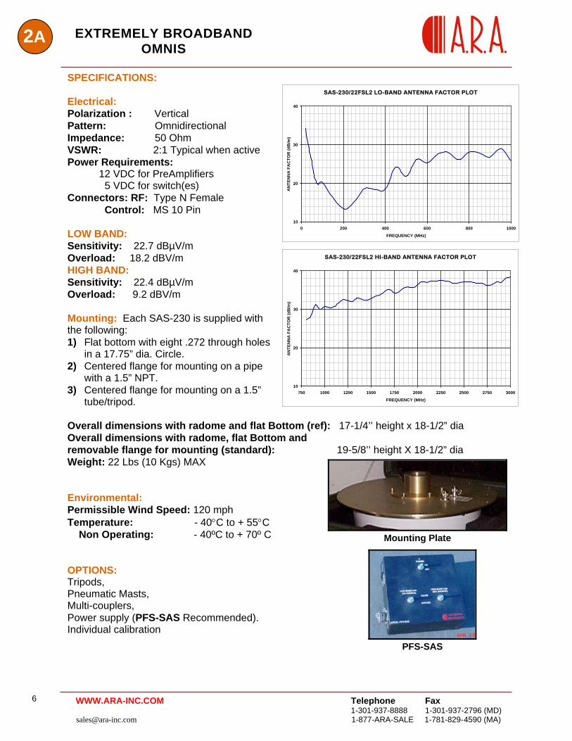
SPECIFICATIONS: SAS-230/22FSL2 LO-BAND ANTENNA FACTOR PLOT
10
20
30
40
0 200 400 600 800 1000FREQUENCY (MHz)
AN
TEN
NA
FA
CTO
R (d
B/m
)
Electrical: Polarization : Vertical Pattern: Omnidirectional Impedance: 50 Ohm VSWR: 2:1 Typical when active Power Requirements: 12 VDC for PreAmplifiers 5 VDC for switch(es) Connectors: RF: Type N Female Control: MS 10 Pin LOW BAND: Sensitivity: 22.7 dBµV/m
SAS-230/22FSL2 HI-BAND ANTENNA FACTOR PLOT
10
20
30
40
750 1000 1250 1500 1750 2000 2250 2500 2750 3000FREQUENCY (MHz)
AN
TEN
NA
FA
CTO
R (d
B/m
)
Overload: 18.2 dBV/m HIGH BAND: Sensitivity: 22.4 dBµV/m Overload: 9.2 dBV/m Mounting: Each SAS-230 is supplied with the following: 1) Flat bottom with eight .272 through holes
in a 17.75” dia. Circle. 2) Centered flange for mounting on a pipe
with a 1.5” NPT. 3) Centered flange for mounting on a 1.5”
tube/tripod. Overall dimensions with radome and flat Bottom (ref): 17-1/4’’ height x 18-1/2” dia Overall dimensions with radome, flat Bottom and removable flange for mounting (standard): 19-5/8’’ height X 18-1/2” dia Weight: 22 Lbs (10 Kgs) MAX
Mounting Plate
Environmental: Permissible Wind Speed: 120 mph Temperature: - 40°C to + 55°C Non Operating: - 40ºC to + 70º C
PFS-SAS
OPTIONS: Tripods, Pneumatic Masts, Multi-couplers, Power supply (PFS-SAS Recommended). Individual calibration
Telephone Fax 1-301-937-8888 1-301-937-2796 (MD) [email protected] 1-877-ARA-SALE 1-781-829-4590 (MA)
6 WWW.ARA-INC.COM
Telephone Fax 1-301-937-8888 1-301-937-2796 (MD) 1-877-ARA-SALE 1-781-829-4590 (MA) [email protected]
7
2AEXTREMELY BROADBAND OMNIS
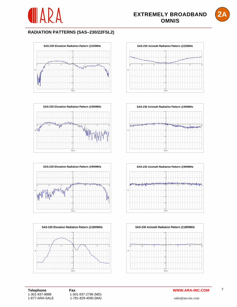
RADIATION PATTERNS (SAS–230/22FSL2)
SAS-230 Elevation Radiation Pattern @225MHz
-20
-15
-10
-5
0
5
10
-90 -60 -30 0 30 60 90
Degrees
dB
SAS-230 Azimuth Radiation Pattern @225MHz
-20
-15
-10
-5
0
5
10
-180 -120 -60 0 60 120 180
Degrees
dB
SAS-230 Elevation Radiation Pattern @450MHz
-20
-15
-10
-5
0
5
10
-90 -60 -30 0 30 60 90
Degrees
dB
SAS-230 Azimuth Radiation Pattern @450MHz
-20
-15
-10
-5
0
5
10
-180 -120 -60 0 60 120 180
Degrees
dB
SAS-230 Elevation Radiation Pattern @900MHz
-20
-15
-10
-5
0
5
10
-90 -60 -30 0 30 60 90
Degrees
dB
SAS-230 Azimuth Radiation Pattern @900MHz
-20
-15
-10
-5
0
5
10
-180 -120 -60 0 60 120 180
Degrees
dB
SAS-230 Elevation Radiation Pattern @1800MHz
-20
-15
-10
-5
0
5
10
-90 -60 -30 0 30 60 90
Degrees
dB
SAS-230 Azimuth Radiation Pattern @1800MHz
-20
-15
-10
-5
0
5
10
-180 -120 -60 0 60 120 180
Degrees
dB
WWW.ARA-INC.COM
2A EXTREMELY BROADBAND
OMNIS
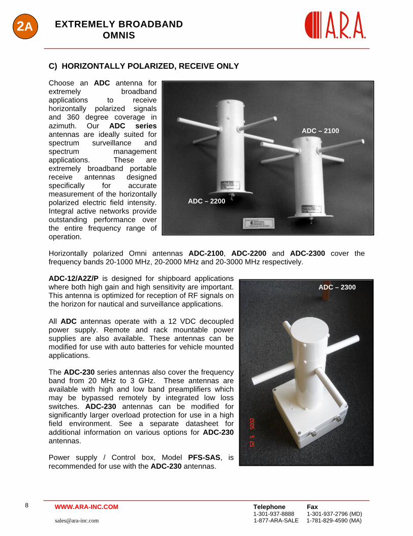
C) HORIZONTALLY POLARIZED, RECEIVE ONLY Choose an ADC antenna for extremely broadband applications to receive horizontally polarized signals and 360 degree coverage in azimuth. Our ADC series antennas are ideally suited for spectrum surveillance and spectrum management applications. These are extremely broadband portable receive antennas designed specifically for accurate measurement of the horizontally polarized electric field intensity. Integral active networks provide outstanding performance over the entire frequency range of operation.
ADC – 2100
ADC – 2200
Horizontally polarized Omni antennas ADC-2100, ADC-2200 and ADC-2300 cover the frequency bands 20-1000 MHz, 20-2000 MHz and 20-3000 MHz respectively. ADC-12/A2Z/P is designed for shipboard applications where both high gain and high sensitivity are important. This antenna is optimized for reception of RF signals on the horizon for nautical and surveillance applications.
Telephone Fax 1-301-937-8888 1-301-937-2796 (MD) [email protected] 1-877-ARA-SALE 1-781-829-4590 (MA)
8
All ADC antennas operate with a 12 VDC decoupled power supply. Remote and rack mountable power supplies are also available. These antennas can be modified for use with auto batteries for vehicle mounted applications. The ADC-230 series antennas also cover the frequency band from 20 MHz to 3 GHz. These antennas are available with high and low band preamplifiers which may be bypassed remotely by integrated low loss switches. ADC-230 antennas can be modified for significantly larger overload protection for use in a high field environment. See a separate datasheet for additional information on various options for ADC-230 antennas. Power supply / Control box, Model PFS-SAS, is recommended for use with the ADC-230 antennas.
ADC – 2300
WWW.ARA-INC.COM
EXTREMELY BROADBAND
OMNIS 2A
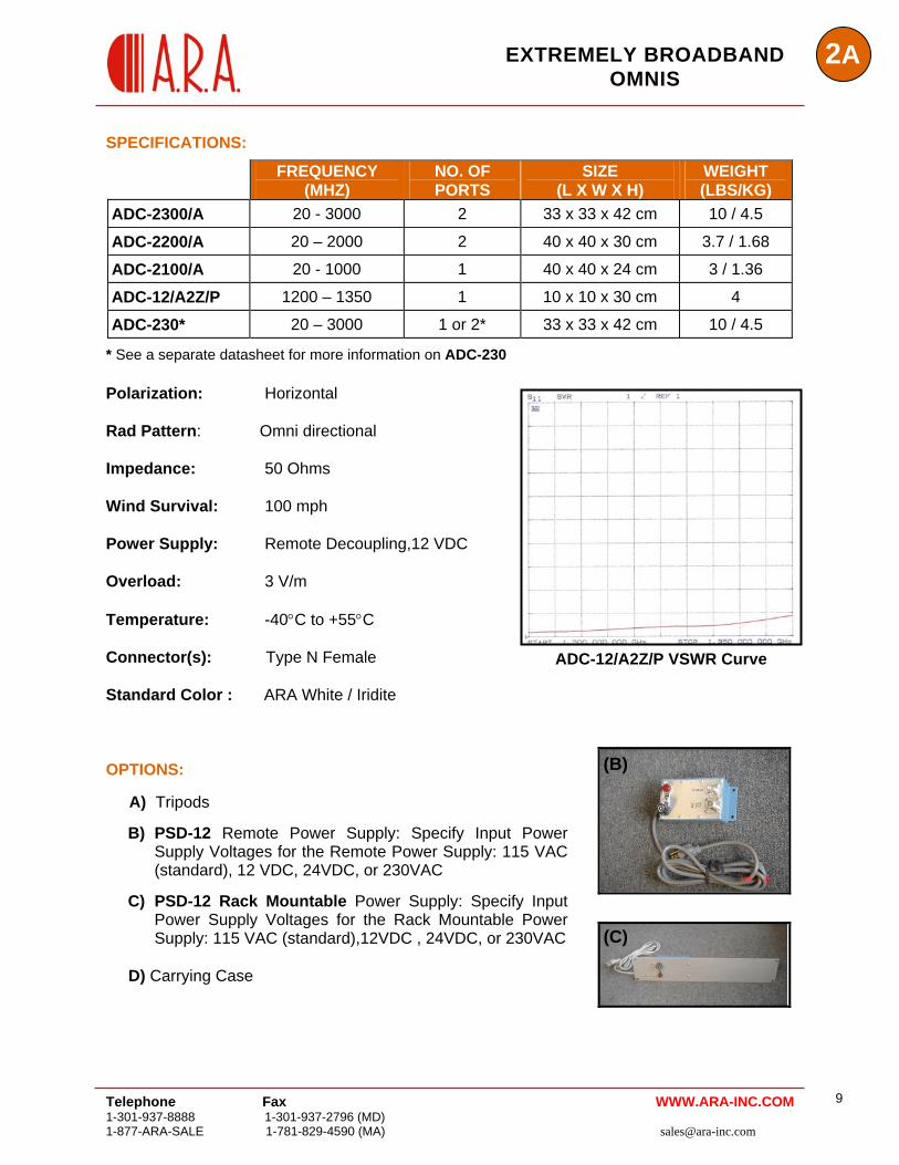
SPECIFICATIONS:
FREQUENCY (MHZ)
NO. OF PORTS
SIZE (L X W X H)
WEIGHT (LBS/KG)
ADC-2300/A 20 - 3000 2 33 x 33 x 42 cm 10 / 4.5
ADC-2200/A 20 – 2000 2 40 x 40 x 30 cm 3.7 / 1.68
ADC-2100/A 20 - 1000 1 40 x 40 x 24 cm 3 / 1.36
ADC-12/A2Z/P 1200 – 1350 1 10 x 10 x 30 cm 4
ADC-230* 20 – 3000 1 or 2* 33 x 33 x 42 cm 10 / 4.5
* See a separate datasheet for more information on ADC-230 Polarization: Horizontal
ADC-12/A2Z/P VSWR Curve
Rad Pattern: Omni directional Impedance: 50 Ohms Wind Survival: 100 mph Power Supply: Remote Decoupling,12 VDC Overload: 3 V/m Temperature: -40°C to +55°C Connector(s): Type N Female Standard Color : ARA White / Iridite
(C)
(B) OPTIONS:
A) Tripods
B) PSD-12 Remote Power Supply: Specify Input Power Supply Voltages for the Remote Power Supply: 115 VAC (standard), 12 VDC, 24VDC, or 230VAC
C) PSD-12 Rack Mountable Power Supply: Specify Input Power Supply Voltages for the Rack Mountable Power Supply: 115 VAC (standard),12VDC , 24VDC, or 230VAC
D) Carrying Case
9 Telephone Fax WWW.ARA-INC.COM
1-301-937-8888 1-301-937-2796 (MD) 1-877-ARA-SALE 1-781-829-4590 (MA) [email protected]
2A EXTREMELY BROADBAND
OMNIS
Telephone Fax 1-301-937-8888 1-301-937-2796 (MD) [email protected] 1-877-ARA-SALE 1-781-829-4590 (MA)
10
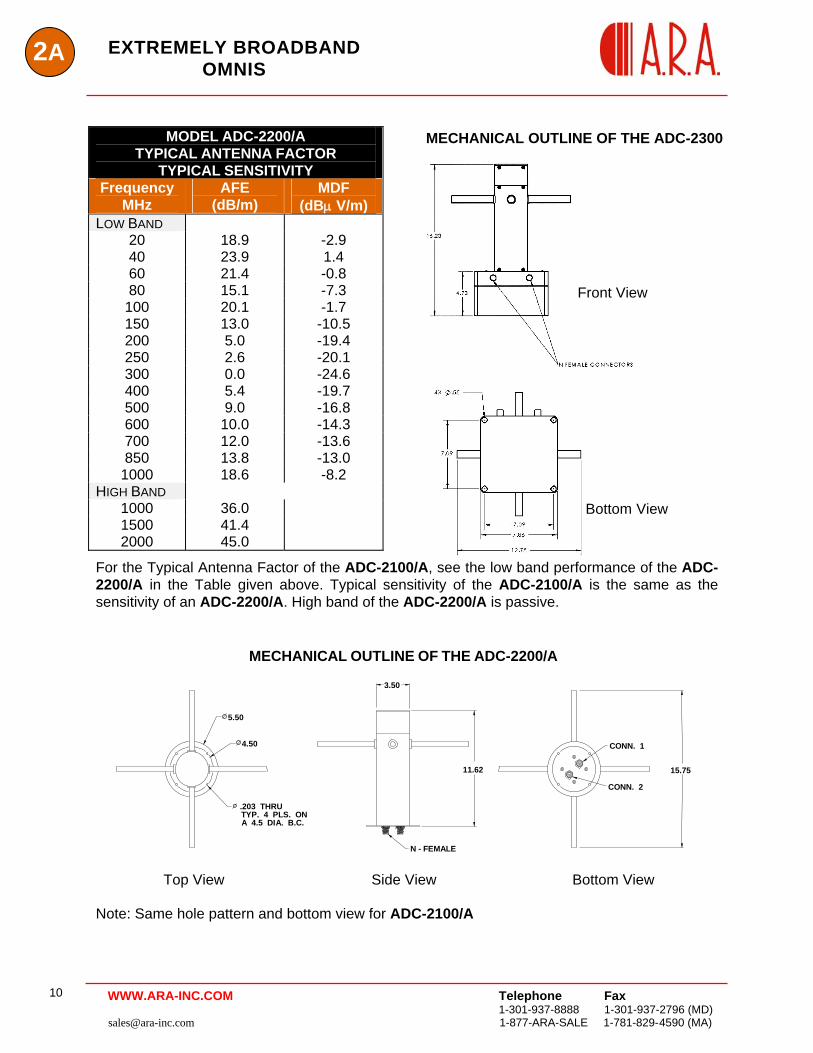
MODEL ADC-2200/A TYPICAL ANTENNA FACTOR
TYPICAL SENSITIVITY Frequency
MHz AFE
(dB/m) MDF
(dBμ V/m) LOW BAND
20 18.9 -2.9 40 23.9 1.4 60 21.4 -0.8 80 15.1 -7.3
100 20.1 -1.7 150 13.0 -10.5 200 5.0 -19.4 250 2.6 -20.1 300 0.0 -24.6 400 5.4 -19.7 500 9.0 -16.8 600 10.0 -14.3 700 12.0 -13.6 850 13.8 -13.0
1000 18.6 -8.2 HIGH BAND
1000 36.0 1500 41.4 2000 45.0
For the Typical Antenna Factor of the ADC-2100/A, see the low band performance of the ADC-2200/A in the Table given above. Typical sensitivity of the ADC-2100/A is the same as the sensitivity of an ADC-2200/A. High band of the ADC-2200/A is passive.
MECHANICAL OUTLINE OF THE ADC-2300
Bottom View
Front View
MECHANICAL OUTLINE OF THE ADC-2200/A
CONN. 1
CONN. 2
N - FEMALE CONNECTORS
15.7511.62
3.50
5.50
4.50
TYP. 4 PLS. ON A 4.5 DIA. B.C. .203 THRU
Top View Side View Bottom View
Note: Same hole pattern and bottom view for ADC-2100/A
WWW.ARA-INC.COM
Telephone Fax 1-301-937-8888 1-301-937-2796 (MD) 1-877-ARA-SALE 1-781-829-4590 (MA) [email protected]
11
2AEXTREMELY BROADBAND OMNIS
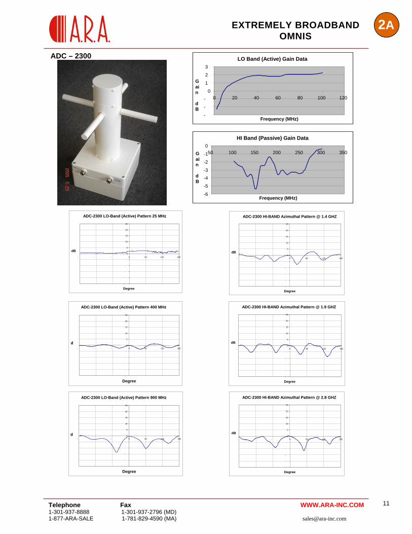
ADC – 2300
LO Band (Active) Gain Data 3
2Gain dB
1
00 20 40 60 80 100 120-
-
-Frequency (MHz)
HI Band (Passive) Gain Data 0
WWW.ARA-INC.COM
-6
-5
-4-3
-2
-150 100 150 200 250 300 350
Frequency (MHz)
Gain dB
ADC-2300 LO-Band (Active) Pattern 25 MHz
-
-
-
-
-
0
0
5
10 15 20 25
- - - 60 120 180
Degree
dB
ADC-2300 HI-BAND Azimuthal Pattern @ 1.4 GHZ25
20
15
10
5
dB 60 120 0
0- - - 180-
-
-
-
-
Degree
ADC-2300 LO-Band (Active) Pattern 400 MHz
-
-
-
-
-
0 5
10 15 20 25
- - - 120 1800 60
Degree
d
ADC-2300 HI-BAND Azimuthal Pattern @ 1.9 GHZ
-
-
-
-
-
0
5
10
15
20
25
- - - 0
dB 60 120 180
Degree
ADC-2300 LO-Band (Active) Pattern 900 MHz
-
-
-
-
-
0 5
10 15 20 25
- - - 120 1800 60
Degree
d
ADC-2300 HI-BAND Azimuthal Pattern @ 2.8 GHZ
-
-
-
-
-- - 120 180
gre
dB0
5
10
15
20
25
- 0 60
De e
2A EXTREMELY BROADBAND
OMNIS
Telephone Fax
1-301-937-8888 1-301-937-2796 (MD) [email protected] 1-877-ARA-SALE 1-781-829-4590 (MA)
12 WWW.ARA-INC.COM
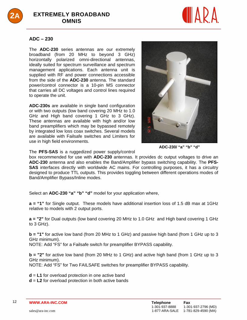
ADC – 230 The ADC-230 series antennas are our extremely broadband (from 20 MHz to beyond 3 GHz) horizontally polarized omni-directional antennas, ideally suited for spectrum surveillance and spectrum management applications. Each antenna unit is supplied with RF and power connections accessible from the side of the ADC-230 antenna. The standard power/control connector is a 10-pin MS connector that carries all DC voltages and control lines required to operate the unit. ADC-230s are available in single band configuration or with two outputs (low band covering 20 MHz to 1.0 GHz and High band covering 1 GHz to 3 GHz). These antennas are available with high and/or low band preamplifiers which may be bypassed remotely by integrated low loss coax switches. Several models are available with Failsafe switches and Limiters for use in high field environments. The PFS-SAS is a ruggedized power supply/control box recommended for use with ADC-230 antennas. It provides dc output voltages to drive an ADC-230 antenna and also enables the Band/Amplifier bypass switching capability. The PFS-SAS interfaces directly with worldwide AC mains. For controlling purposes, it has a circuitry designed to produce TTL outputs. This provides toggling between different operations modes of Band/Amplifier Bypass/Inline modes.
ADC-230/ “a” “b” “d”
Select an ADC-230 “a” “b” “d” model for your application where, a = “1” for Single output. These models have additional insertion loss of 1.5 dB max at 1GHz relative to models with 2 output ports. a = "2" for Dual outputs (low band covering 20 MHz to 1.0 GHz and High band covering 1 GHz to 3 GHz). b = "1" for active low band (from 20 MHz to 1 GHz) and passive high band (from 1 GHz up to 3 GHz minimum). NOTE: Add “FS” for a Failsafe switch for preamplifier BYPASS capability. b = "2" for active low band (from 20 MHz to 1 GHz) and active high band (from 1 GHz up to 3 GHz minimum). NOTE: Add “FS” for Two FAILSAFE switches for preamplifier BYPASS capability. d = L1 for overload protection in one active band d = L2 for overload protection in both active bands
2AEXTREMELY BROADBAND
OMNIS
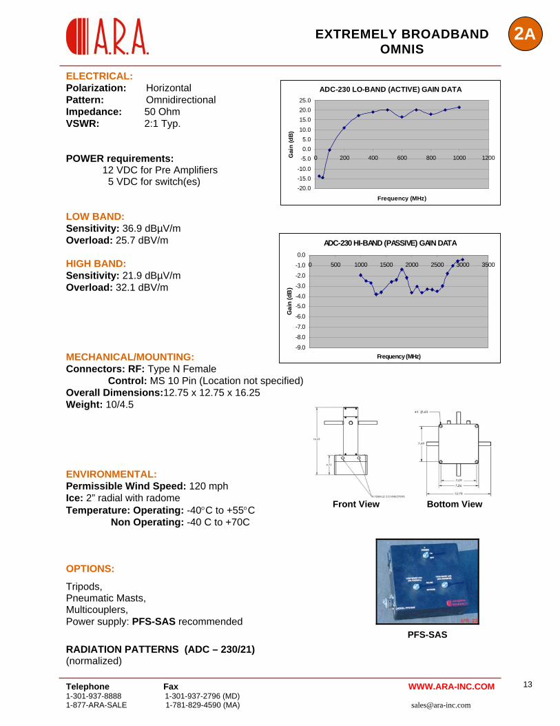
ELECTRICAL: ADC-230 LO-BAND (ACTIVE) GAIN DATA
-20.0-15.0-10.0
-5.00.05.0
10.0
15.020.025.0
0 200 400 600 800 1000 1200
Frequency (MHz)
Gai
n (d
B)
ADC-230 HI-BAND (PASSIVE) GAIN DATA
-9.0
-8.0
-7.0
-6.0
-5.0-4.0
-3.0
-2.0
-1.0
0.00 500 1000 1500 2000 2500 3000 3500
Frequency (MHz)
Gai
n (d
B)
Polarization: Horizontal Pattern: Omnidirectional Impedance: 50 Ohm VSWR: 2:1 Typ. POWER requirements: 12 VDC for Pre Amplifiers 5 VDC for switch(es) LOW BAND: Sensitivity: 36.9 dBµV/m Overload: 25.7 dBV/m HIGH BAND: Sensitivity: 21.9 dBµV/m Overload: 32.1 dBV/m MECHANICAL/MOUNTING: Connectors: RF: Type N Female Control: MS 10 Pin (Location not specified) Overall Dimensions:12.75 x 12.75 x 16.25 Weight: 10/4.5
Front View Bottom View
ENVIRONMENTAL: Permissible Wind Speed: 120 mph Ice: 2” radial with radome Temperature: Operating: -40°C to +55°C Non Operating: -40 C to +70C
PFS-SAS
OPTIONS:
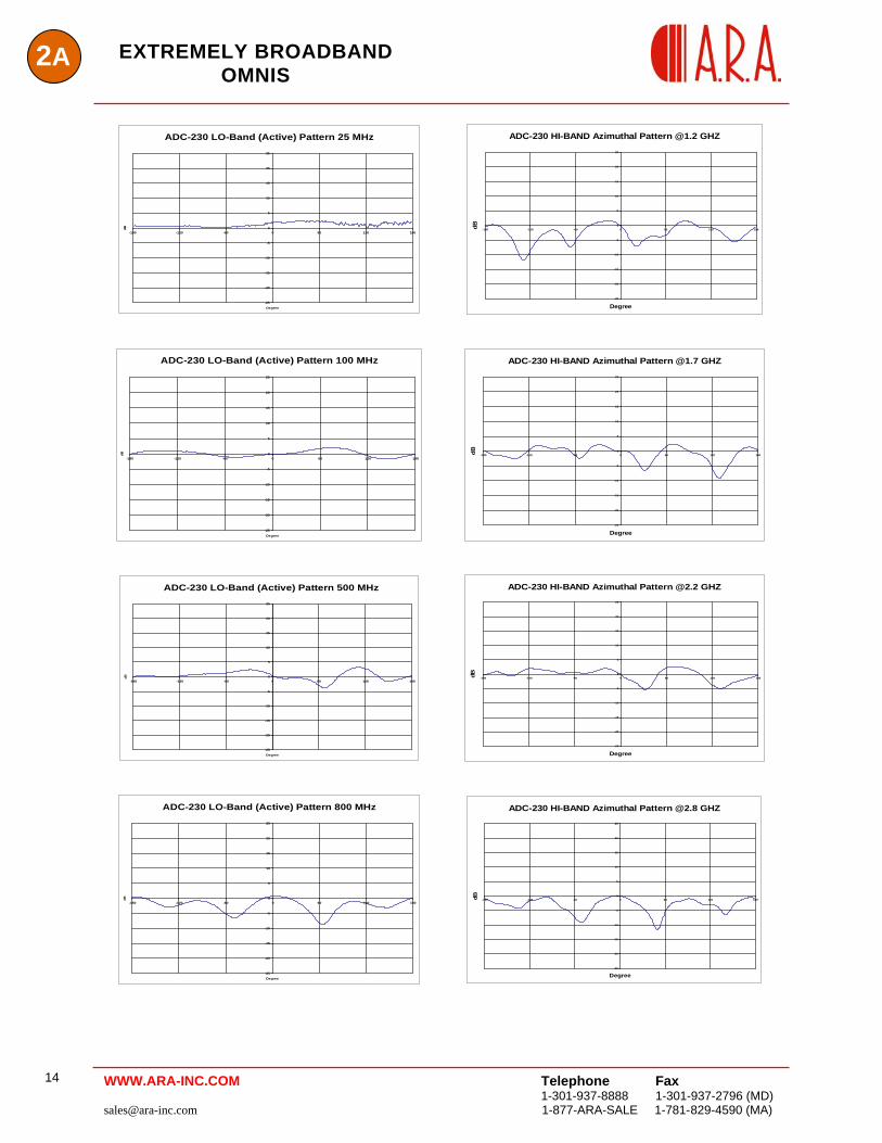
Tripods, Pneumatic Masts, Multicouplers, Power supply: PFS-SAS recommended RADIATION PATTERNS (ADC – 230/21) (normalized)
Telephone Fax 1-301-937-8888 1-301-937-2796 (MD) 1-877-ARA-SALE 1-781-829-4590 (MA) [email protected]
13WWW.ARA-INC.COM
Telephone Fax
1-301-937-8888 1-301-937-2796 (MD) [email protected] 1-877-ARA-SALE 1-781-829-4590 (MA)
14
2A EXTREMELY BROADBAND OMNIS
WWW.ARA-INC.COM
ADC-230 LO-Band (Active) Pattern 25 MHz
-25
-20
-15
-10
-5
0
5
10
15
20
25
-180 -120 -60 0 60 120 180
Degree
dB
ADC-230 HI-BAND Azimuthal Pattern @1.2 GHZ
-25
-20
-15
-10
-5
0
5
10
15
20
25
-180 -120 -60 0 60 120 180
Degree
dB
ADC-230 LO-Band (Active) Pattern 100 MHz
-25
-20
-15
-10
-5
0
5
10
15
20
25
-180 -120 -60 0 60 120 180
Degree
dB
ADC-230 HI-BAND Azimuthal Pattern @1.7 GHZ
-25
-20
-15
-10
-5
0
5
10
15
20
25
-180 -120 -60 0 60 120 180
Degree
dB
ADC-230 LO-Band (Active) Pattern 500 MHz
-25
-20
-15
-10
-5
0
5
10
15
20
25
-180 -120 -60 0 60 120 180
Degree
dB
ADC-230 HI-BAND Azimuthal Pattern @2.2 GHZ
-25
-20
-15
-10
-5
0
5
10
15
20
25
-180 -120 -60 0 60 120 180
Degree
dB
ADC-230 LO-Band (Active) Pattern 800 MHz
-25
-20
-15
-10
-5
0
5
10
15
20
25
-180 -120 -60 0 60 120 180
Degree
dB
ADC-230 HI-BAND Azimuthal Pattern @2.8 GHZ
-25
-20
-15
-10
-5
0
5
10
15
20
25
-180 -120 -60 0 60 120 180
Degree
dB
EXTREMELY BROADBAND VERTICALLY POLARIZED
2A
ANTENNAS
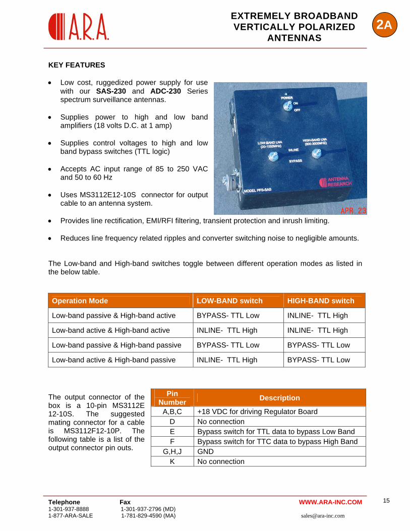
KEY FEATURES • Low cost, ruggedized power supply for use
with our SAS-230 and ADC-230 Series spectrum surveillance antennas.
Telephone Fax 1-301-937-8888 1-301-937-2796 (MD) 1-877-ARA-SALE 1-781-829-4590 (MA) [email protected]
15WWW.ARA-INC.COM
• Supplies power to high and low band
amplifiers (18 volts D.C. at 1 amp) • Supplies control voltages to high and low
band bypass switches (TTL logic) • Accepts AC input range of 85 to 250 VAC
and 50 to 60 Hz • Uses MS3112E12-10S connector for output
cable to an antenna system. • Provides line rectification, EMI/RFI filtering, transient protection and inrush limiting. • Reduces line frequency related ripples and converter switching noise to negligible amounts. The Low-band and High-band switches toggle between different operation modes as listed in the below table. Operation Mode LOW-BAND switch HIGH-BAND switch
Low-band passive & High-band active BYPASS- TTL Low INLINE- TTL High
Low-band active & High-band active INLINE- TTL High INLINE- TTL High
Low-band passive & High-band passive BYPASS- TTL Low BYPASS- TTL Low
Low-band active & High-band passive INLINE- TTL High BYPASS- TTL Low The output connector of the box is a 10-pin MS3112E 12-10S. The suggested mating connector for a cable is MS3112F12-10P. The following table is a list of the output connector pin outs.
Pin Number Description
A,B,C +18 VDC for driving Regulator Board D No connection E Bypass switch for TTL data to bypass Low Band F Bypass switch for TTC data to bypass High Band
G,H,J GND K No connection
2BBROADBAND OMNI
ANTENNAS
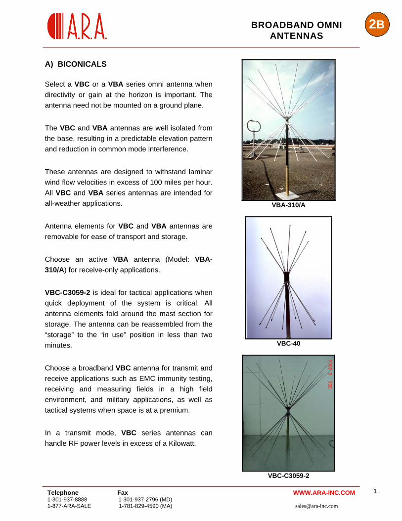
A) BICONICALS Select a VBC or a VBA series omni antenna when directivity or gain at the horizon is important. The antenna need not be mounted on a ground plane. The VBC and VBA antennas are well isolated from the base, resulting in a predictable elevation pattern and reduction in common mode interference. These antennas are designed to withstand laminar wind flow velocities in excess of 100 miles per hour. All VBC and VBA series antennas are intended for all-weather applications. Antenna elements for VBC and VBA antennas are removable for ease of transport and storage. Choose an active VBA antenna (Model: VBA-310/A) for receive-only applications. VBC-C3059-2 is ideal for tactical applications when quick deployment of the system is critical. All antenna elements fold around the mast section for storage. The antenna can be reassembled from the “storage” to the “in use” position in less than two minutes. Choose a broadband VBC antenna for transmit and receive applications such as EMC immunity testing, receiving and measuring fields in a high field environment, and military applications, as well as tactical systems when space is at a premium. In a transmit mode, VBC series antennas can handle RF power levels in excess of a Kilowatt.
VBA-310/A
VBC-40
VBC-C3059-2
Telephone Fax 1-301-937-8888 1-301-937-2796 (MD) 1-877-ARA-SALE 1-781-829-4590 (MA) [email protected]
1 WWW.ARA-INC.COM
2B BROADBAND OMNI
ANTENNAS
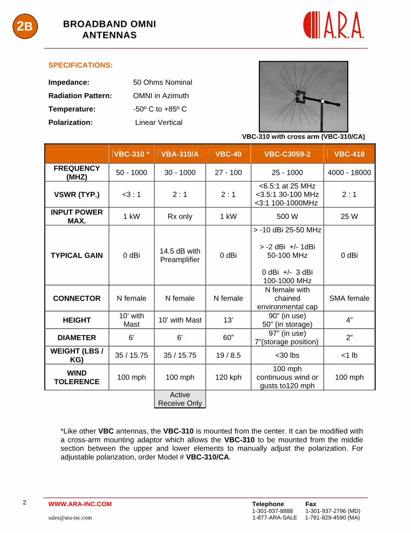
SPECIFICATIONS:
VBC-310 with cross arm (VBC-310/CA)
Impedance: 50 Ohms Nominal
Radiation Pattern: OMNI in Azimuth
Temperature: -50º C to +85º C
Polarization: Linear Vertical
VBC-310 * VBA-310/A VBC-40 VBC-C3059-2 VBC-418
FREQUENCY (MHZ) 50 - 1000 30 - 1000 27 - 100 25 - 1000 4000 - 18000
VSWR (TYP.) <3 : 1 2 : 1 2 : 1 <6.5:1 at 25 MHz
<3.5:1 30-100 MHz <3:1 100-1000MHz
2 : 1
INPUT POWER MAX. 1 kW Rx only 1 kW 500 W 25 W
TYPICAL GAIN 0 dBi 14.5 dB with Preamplifier 0 dBi
> -10 dBi 25-50 MHz
> -2 dBi +/- 1dBi 50-100 MHz
0 dBi +/- 3 dBi 100-1000 MHz
0 dBi
CONNECTOR N female N female N female N female with
chained environmental cap
SMA female
HEIGHT 10’ with Mast 10’ with Mast 13’ 90” (in use)
50” (in storage) 4”
DIAMETER 6’ 6’ 60” 97” (in use) 7”(storage position) 2”
WEIGHT (LBS / KG) 35 / 15.75 35 / 15.75 19 / 8.5 <30 lbs <1 lb
WIND TOLERENCE 100 mph 100 mph 120 kph
100 mph continuous wind or gusts to120 mph
100 mph
Active Receive Only
*Like other VBC antennas, the VBC-310 is mounted from the center. It can be modified with a cross-arm mounting adaptor which allows the VBC-310 to be mounted from the middle section between the upper and lower elements to manually adjust the polarization. For adjustable polarization, order Model # VBC-310/CA.
Telephone Fax
1-301-937-8888 1-301-937-2796 (MD) [email protected] 1-877-ARA-SALE 1-781-829-4590 (MA)
2 WWW.ARA-INC.COM
2BBROADBAND OMNI
ANTENNAS
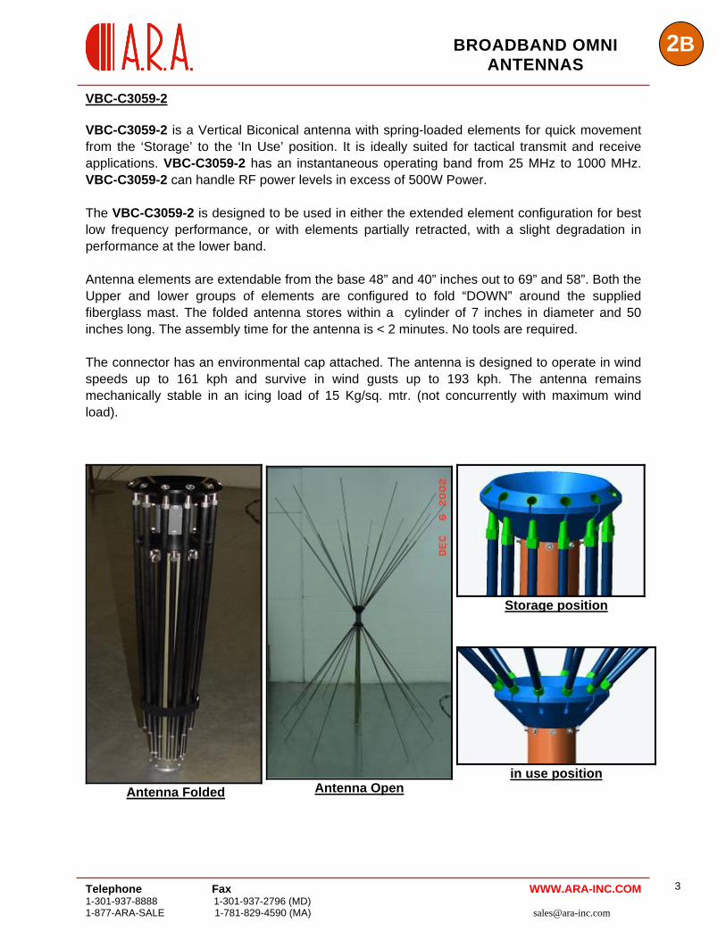
VBC-C3059-2 VBC-C3059-2 is a Vertical Biconical antenna with spring-loaded elements for quick movement from the ‘Storage’ to the ‘In Use’ position. It is ideally suited for tactical transmit and receive applications. VBC-C3059-2 has an instantaneous operating band from 25 MHz to 1000 MHz. VBC-C3059-2 can handle RF power levels in excess of 500W Power. The VBC-C3059-2 is designed to be used in either the extended element configuration for best low frequency performance, or with elements partially retracted, with a slight degradation in performance at the lower band. Antenna elements are extendable from the base 48” and 40” inches out to 69” and 58”. Both the Upper and lower groups of elements are configured to fold “DOWN” around the supplied fiberglass mast. The folded antenna stores within a cylinder of 7 inches in diameter and 50 inches long. The assembly time for the antenna is < 2 minutes. No tools are required. The connector has an environmental cap attached. The antenna is designed to operate in wind speeds up to 161 kph and survive in wind gusts up to 193 kph. The antenna remains mechanically stable in an icing load of 15 Kg/sq. mtr. (not concurrently with maximum wind load).
Storage position
Antenna Folded Antenna Open in use position
Telephone Fax 1-301-937-8888 1-301-937-2796 (MD) 1-877-ARA-SALE 1-781-829-4590 (MA) [email protected]
3 WWW.ARA-INC.COM
Telephone Fax
1-301-937-8888 1-301-937-2796 (MD) [email protected] 1-877-ARA-SALE 1-781-829-4590 (MA)
4
2B BROADBAND OMNI ANTENNAS
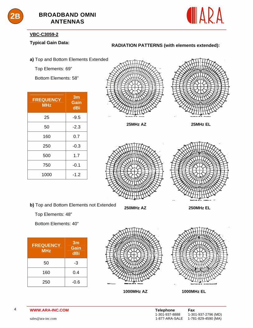
VBC-C3059-2
Typical Gain Data: RADIATION PATTERNS (with elements extended):
25MHz AZ 25MHz EL
a) Top and Bottom Elements Extended
Top Elements: 69”
Bottom Elements: 58”
WWW.ARA-INC.COM
250MHz AZ 250MHz EL
1000MHz AZ 1000MHz EL
FREQUENCY MHz
3m Gain dBi
25 -9.5
50 -2.3
160 0.7
250 -0.3
500 1.7
750 -0.1
1000 -1.2
b) Top and Bottom Elements not Extended
Top Elements: 48”
Bottom Elements: 40”
FREQUENCY MHz
3m Gain dBi
50 -3
160 0.4
250 -0.6
2BBROADBAND OMNI
ANTENNAS
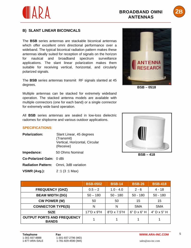
B) SLANT LINEAR BICONICALS
The BSB series antennas are stackable biconical antennas which offer excellent omni directional performance over a wideband. The typical biconical radiation pattern makes these antennas ideally suited for reception of signals on the horizon for nautical and broadband spectrum surveillance applications. The slant linear polarization makes them suitable for receiving vertical, horizontal, and circularly polarized signals. The BSB series antennas transmit RF signals slanted at 45 degrees. Multiple antennas can be stacked for extremely wideband operation. The stacked antenna models are available with multiple connectors (one for each band) or a single connector for extremely wide band operation. All BSB series antennas are sealed in low-loss dielectric radomes for shipborne and various outdoor applications. SPECIFICATIONS:
Polarization: Slant Linear, 45 degrees (Transmit)
Vertical, Horizontal, Circular (Receive)
Impedance: 50 Ohms Nominal
Co-Polarized Gain: 0 dBi
Radiation Pattern: Omni, 3dB variation
VSWR (Avg.): 2 :1 (3 :1 Max)
BSB – 0518
BSB – 418
BSB-0502 BSB-14 BSB-26 BSB-418
FREQUENCY (GHZ) 0.5 – 2 1.0 - 4.0 2 - 6 4 - 18
BEAM WIDTH (DG) 50 – 180 50 - 180 50 - 180 50 - 180 CW POWER (W) 50 50 15 15
CONNECTOR TYPE(S) N N SMA SMA SIZE 17”D x 9”H 8”D x 7.5”H 6” D x 6” H 4” D x 5” H
OUTPUT PORTS AND FREQUENCY BANDS 1 1 1 1
Telephone Fax 1-301-937-8888 1-301-937-2796 (MD) 1-877-ARA-SALE 1-781-829-4590 (MA) [email protected]
5 WWW.ARA-INC.COM
2B BROADBAND OMNI
ANTENNAS
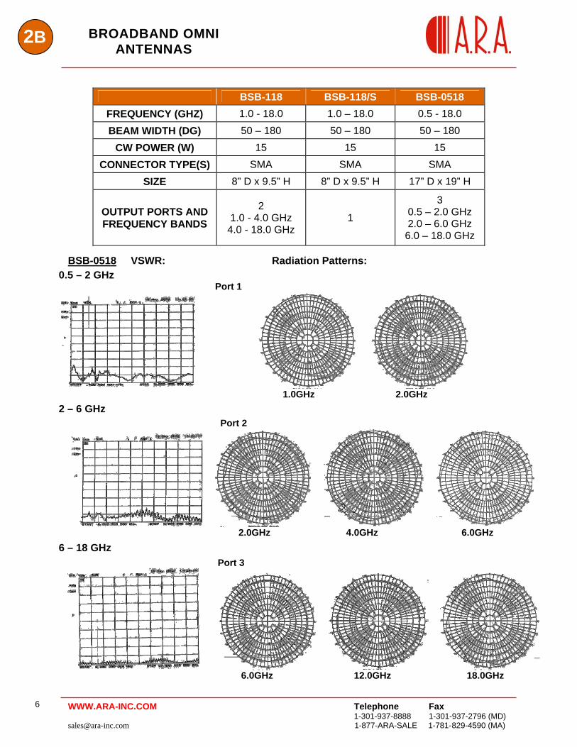
BSB-118 BSB-118/S BSB-0518 FREQUENCY (GHZ) 1.0 - 18.0 1.0 – 18.0 0.5 - 18.0 BEAM WIDTH (DG) 50 – 180 50 – 180 50 – 180
CW POWER (W) 15 15 15 CONNECTOR TYPE(S) SMA SMA SMA
SIZE 8” D x 9.5” H 8” D x 9.5” H 17” D x 19” H
OUTPUT PORTS AND FREQUENCY BANDS
2 1.0 - 4.0 GHz
4.0 - 18.0 GHz 1
3 0.5 – 2.0 GHz 2.0 – 6.0 GHz
6.0 – 18.0 GHz BSB-0518 VSWR: Radiation Patterns:
0.5 – 2 GHz Port 1
1.0GHz 2.0GHz 2 – 6 GHz Port 2
2.0GHz 4.0GHz 6.0GHz 6 – 18 GHz Port 3
6.0GHz 12.0GHz 18.0GHz
Telephone Fax
1-301-937-8888 1-301-937-2796 (MD) [email protected] 1-877-ARA-SALE 1-781-829-4590 (MA)
6 WWW.ARA-INC.COM
Telephone Fax 1-301-937-8888 1-301-937-2796 (MD) 1-877-ARA-SALE 1-781-829-4590 (MA) [email protected]
7
2BBROADBAND OMNI ANTENNAS
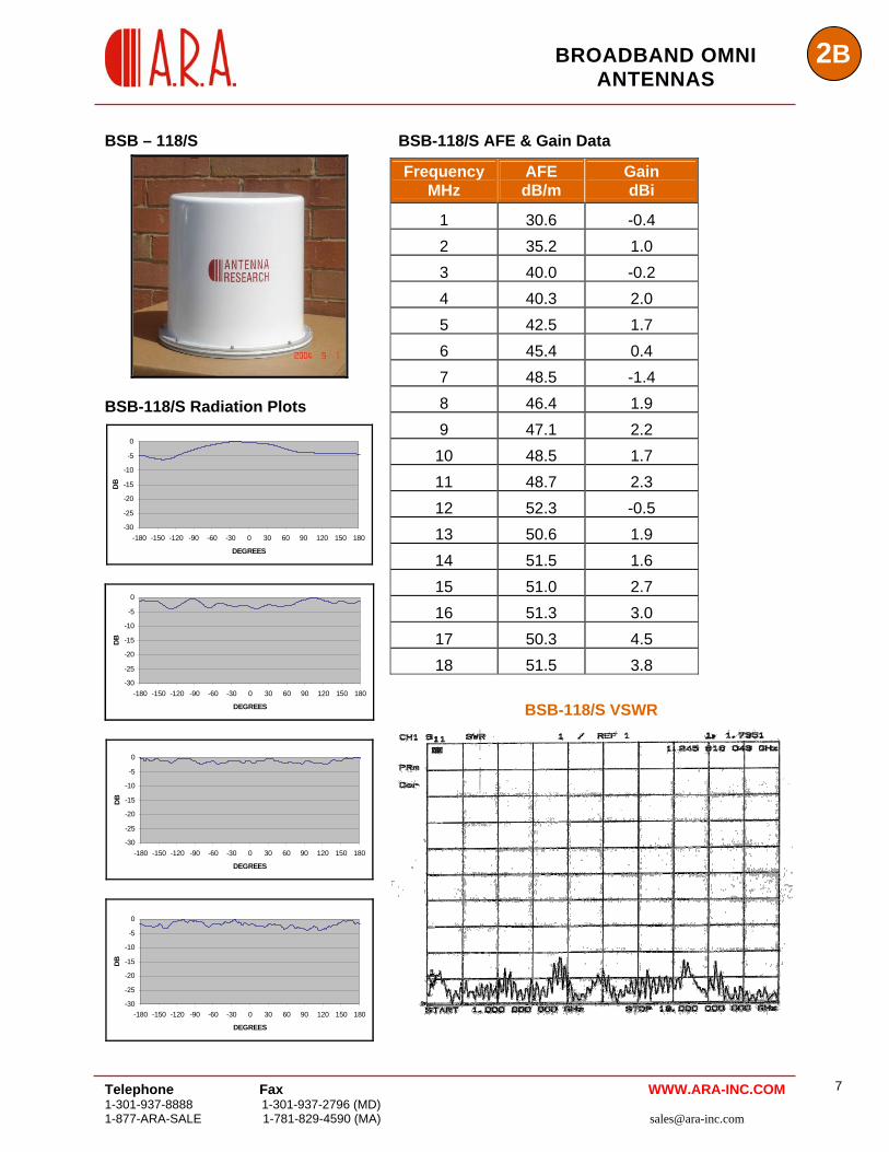
BSB – 118/S
BSB-118/S Radiation Plots
-30
-25
-20
-15
-10
-5
0
-180 -150 -120 -90 -60 -30 0 30 60 90 120 150 180
DEGREES
DB
-30
-25
-20
-15
-10
-5
0
-180 -150 -120 -90 -60 -30 0 30 60 90 120 150 180
DEGREES
DB
-30
-25
-20
-15
-10
-5
0
-180 -150 -120 -90 -60 -30 0 30 60 90 120 150 180
DEGREES
DB
-30
-25
-20
-15
-10
-5
0
-180 -150 -120 -90 -60 -30 0 30 60 90 120 150 180
DEGREES
DB
BSB-118/S AFE & Gain Data
Frequency AFE Gain
WWW.ARA-INC.COM
MHz dB/m dBi
1 30.6 -0.4 2 35.2 1.0 3 40.0 -0.2 4 40.3 2.0 5 42.5 1.7 6 45.4 0.4 7 48.5 -1.4 8 46.4 1.9 9 47.1 2.2
10 48.5 1.7 11 48.7 2.3 12 52.3 -0.5 13 50.6 1.9 14 51.5 1.6 15 51.0 2.7 16 51.3 3.0 17 50.3 4.5 18 51.5 3.8
BSB-118/S VSWR
2B BROADBAND OMNI
ANTENNAS
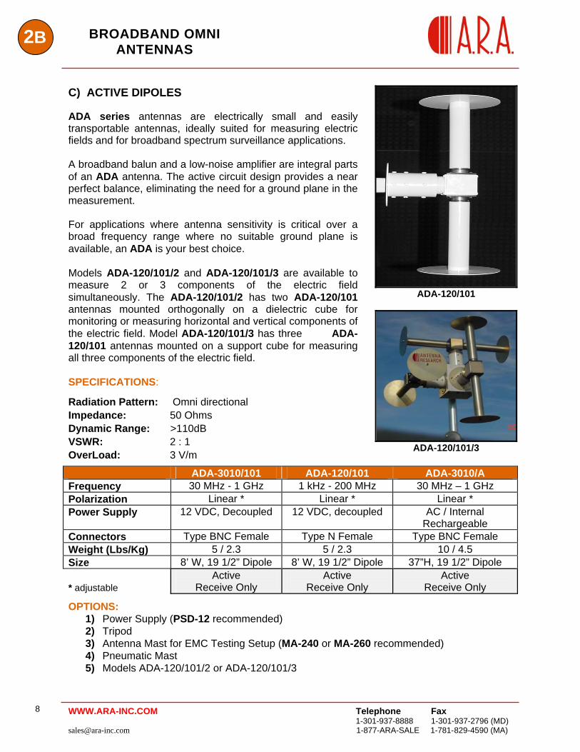
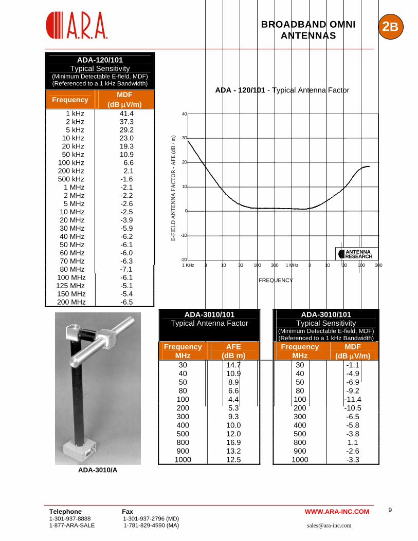
C) ACTIVE DIPOLES ADA series antennas are electrically small and easily transportable antennas, ideally suited for measuring electric fields and for broadband spectrum surveillance applications. A broadband balun and a low-noise amplifier are integral parts of an ADA antenna. The active circuit design provides a near perfect balance, eliminating the need for a ground plane in the measurement. For applications where antenna sensitivity is critical over a broad frequency range where no suitable ground plane is available, an ADA is your best choice. Models ADA-120/101/2 and ADA-120/101/3 are available to measure 2 or 3 components of the electric field simultaneously. The ADA-120/101/2 has two ADA-120/101 antennas mounted orthogonally on a dielectric cube for monitoring or measuring horizontal and vertical components of the electric field. Model ADA-120/101/3 has three ADA-120/101 antennas mounted on a support cube for measuring all three components of the electric field. SPECIFICATIONS:
Radiation Pattern: Omni directional Impedance: 50 Ohms Dynamic Range: >110dB VSWR: 2 : 1 OverLoad: 3 V/m
ADA-120/101
ADA-120/101/3
ADA-3010/101 ADA-120/101 ADA-3010/A Frequency 30 MHz - 1 GHz 1 kHz - 200 MHz 30 MHz – 1 GHz Polarization Linear * Linear * Linear * Power Supply 12 VDC, Decoupled 12 VDC, decoupled AC / Internal
Rechargeable Connectors Type BNC Female Type N Female Type BNC Female Weight (Lbs/Kg) 5 / 2.3 5 / 2.3 10 / 4.5 Size 8’ W, 19 1/2” Dipole 8’ W, 19 1/2” Dipole 37”H, 19 1/2” Dipole
* adjustable Active
Receive Only Active
Receive Only Active
Receive Only
OPTIONS: 1) Power Supply (PSD-12 recommended) 2) Tripod 3) Antenna Mast for EMC Testing Setup (MA-240 or MA-260 recommended) 4) Pneumatic Mast 5) Models ADA-120/101/2 or ADA-120/101/3
Telephone Fax
1-301-937-8888 1-301-937-2796 (MD) [email protected] 1-877-ARA-SALE 1-781-829-4590 (MA)
8 WWW.ARA-INC.COM
Telephone Fax 1-301-937-8888 1-301-937-2796 (MD) 1-877-ARA-SALE 1-781-829-4590 (MA) [email protected]
9
2BBROADBAND OMNI ANTENNAS
ADA-120/101 Typical Sensitivity
(Minimum Detectable E-field, MDF) (Referenced to a 1 kHz Bandwidth)
Frequency MDF
(dB μV/m)
ADA - 120/101 - Typical Antenna Factor
1 kHz 41.4 2 kHz 37.3 5 kHz 29.2 10 kHz 23.0 20 kHz 19.3 50 kHz 10.9 100 kHz 6.6 200 kHz 2.1 500 kHz -1.6 1 MHz -2.1 2 MHz -2.2 5 MHz -2.6 10 MHz -2.5 20 MHz -3.9 30 MHz -5.9 40 MHz -6.2 50 MHz -6.1 60 MHz -6.0 70 MHz -6.3
WWW.ARA-INC.COM
80 MHz -7.1 100 MHz -6.1 125 MHz -5.1 150 MHz -5.4 200 MHz -6.5
10 1003 30 100 300 1 MHz 3 10 30 300
30
40
20
10
0
-10
-201 KHz
A N T E N N ARESEARCH
E-FI
ELD
AN
TEN
NA
FA
CTO
R -
AFE
(dB
/ m
)
FREQUENCY
ADA-3010/101 Typical Antenna Factor
ADA-3010/101 Typical Sensitivity
(Minimum Detectable E-field, MDF) (Referenced to a 1 kHz Bandwidth)
Frequency MHz
AFE (dB m)
Frequency MDF MHz (dB μV/m)
30 14.7 30 -1.1 40 10.9 40 -4.9 50 8.9 50 -6.9 80 6.6 80 -9.2 100 4.4 100 -11.4 200 5.3 200 -10.5 300 9.3 300 -6.5 400 10.0 400 -5.8 500 12.0 500 -3.8 800 16.9 800 1.1 900 13.2 900 -2.6 1000 12.5 1000 -3.3
ADA-3010/A
2B BROADBAND OMNI
ANTENNAS
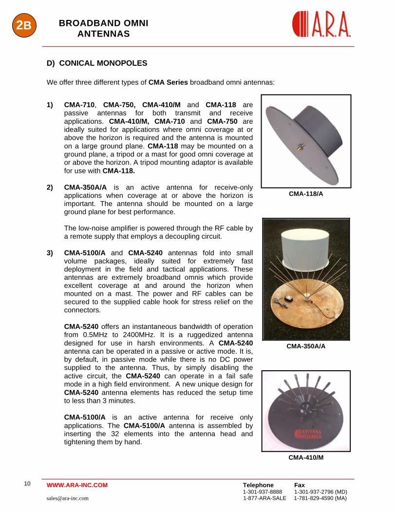
D) CONICAL MONOPOLES
We offer three different types of CMA Series broadband omni antennas: 1) CMA-710, CMA-750, CMA-410/M and CMA-118 are
passive antennas for both transmit and receive applications. CMA-410/M, CMA-710 and CMA-750 are ideally suited for applications where omni coverage at or above the horizon is required and the antenna is mounted on a large ground plane. CMA-118 may be mounted on a ground plane, a tripod or a mast for good omni coverage at or above the horizon. A tripod mounting adaptor is available for use with CMA-118.
2) CMA-350A/A is an active antenna for receive-only
applications when coverage at or above the horizon is important. The antenna should be mounted on a large ground plane for best performance. The low-noise amplifier is powered through the RF cable by a remote supply that employs a decoupling circuit.
3) CMA-5100/A and CMA-5240 antennas fold into small
volume packages, ideally suited for extremely fast deployment in the field and tactical applications. These antennas are extremely broadband omnis which provide excellent coverage at and around the horizon when mounted on a mast. The power and RF cables can be secured to the supplied cable hook for stress relief on the connectors.
CMA-5240 offers an instantaneous bandwidth of operation from 0.5MHz to 2400MHz. It is a ruggedized antenna designed for use in harsh environments. A CMA-5240 antenna can be operated in a passive or active mode. It is, by default, in passive mode while there is no DC power supplied to the antenna. Thus, by simply disabling the active circuit, the CMA-5240 can operate in a fail safe mode in a high field environment. A new unique design for CMA-5240 antenna elements has reduced the setup time to less than 3 minutes.
CMA-5100/A is an active antenna for receive only applications. The CMA-5100/A antenna is assembled by inserting the 32 elements into the antenna head and tightening them by hand.
CMA-118/A
CMA-350A/A
CMA-410/M
Telephone Fax
1-301-937-8888 1-301-937-2796 (MD) [email protected] 1-877-ARA-SALE 1-781-829-4590 (MA)
10 WWW.ARA-INC.COM
2BBROADBAND OMNI
ANTENNAS
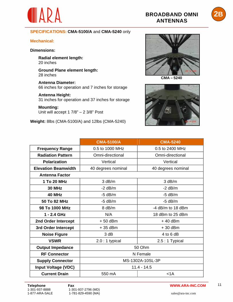
SPECIFICATIONS: CMA-5100/A and CMA-5240 only Mechanical: Dimensions:
Radial element length: 20 inches
Ground Plane element length: 28 inches
Antenna Diameter: 66 inches for operation and 7 inches for storage
Antenna Height: 31 inches for operation and 37 inches for storage
Mounting: Unit will accept 1 7/8” – 2 3/8” Post Weight: 8lbs (CMA-5100/A) and 12lbs (CMA-5240)
CMA – 5240
CMA-5100/A CMA-5240 Frequency Range 0.5 to 1000 MHz 0.5 to 2400 MHz Radiation Pattern Omni-directional Omni-directional
Polarization Vertical Vertical Elevation Beamwidth 40 degrees nominal 40 degrees nominal
Antenna Factor 1 To 20 MHz 3 dB/m 3 dB/m
30 MHz -2 dB/m -2 dB/m 40 MHz -5 dB/m -5 dB/m
50 To 82 MHz -5 dB/m -5 dB/m 98 To 1000 MHz 8 dB/m -4 dB/m to 18 dBm
1 - 2.4 GHz N/A 18 dBm to 25 dBm 2nd Order Intercept + 50 dBm + 40 dBm 3rd Order Intercept + 35 dBm + 30 dBm
Noise Figure 3 dB 4 to 6 dB VSWR 2.0 : 1 typical 2.5 : 1 Typical
Output Impedance 50 Ohm RF Connector N Female
Supply Connector MS-1302A-10SL-3P Input Voltage (VDC) 11.4 - 14.5
Current Drain 550 mA <1A
Telephone Fax 1-301-937-8888 1-301-937-2796 (MD) 1-877-ARA-SALE 1-781-829-4590 (MA) [email protected]
11WWW.ARA-INC.COM
Telephone Fax
1-301-937-8888 1-301-937-2796 (MD) [email protected] 1-877-ARA-SALE 1-781-829-4590 (MA)
12
2B BROADBAND OMNI ANTENNAS
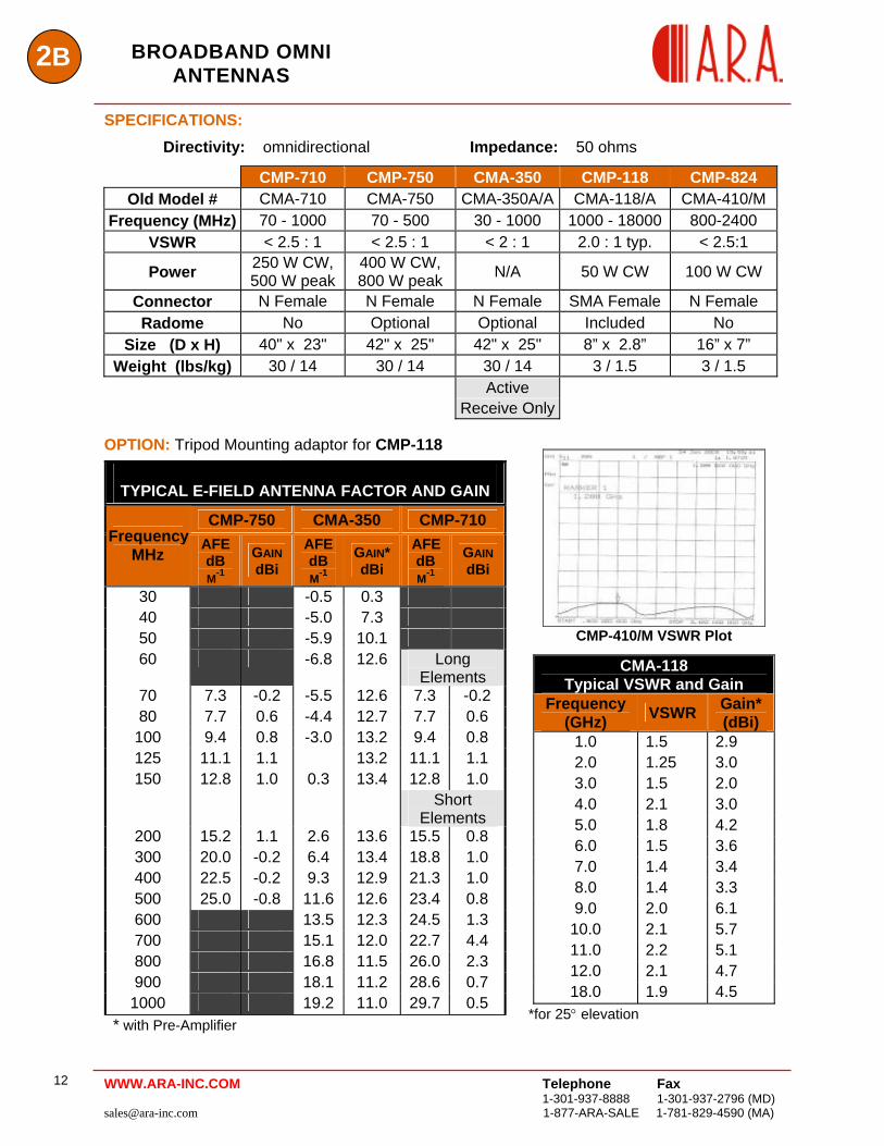
SPECIFICATIONS:
Directivity: omnidirectional Impedance: 50 ohms
CMP-710 CMP-750 CMA-350 CMP-118 CMP-824 Old Model # CMA-710 CMA-750 CMA-350A/A CMA-118/A CMA-410/M
Frequency (MHz) 70 - 1000 70 - 500 30 - 1000 1000 - 18000 800-2400 VSWR < 2.5 : 1 < 2.5 : 1 < 2 : 1 2.0 : 1 typ. < 2.5:1
Power 250 W CW, 500 W peak
400 W CW, 800 W peak N/A 50 W CW 100 W CW
Connector N Female N Female N Female SMA Female N Female Radome No Optional Optional Included No
Size (D x H) 40" x 23" 42" x 25" 42" x 25" 8” x 2.8” 16” x 7” Weight (lbs/kg) 30 / 14 30 / 14 30 / 14 3 / 1.5 3 / 1.5
Active Receive Only
OPTION: Tripod Mounting adaptor for CMP-118
TYPICAL E-FIELD ANTENNA FACTOR AND GAIN
CMP-750 CMA-350 CMP-710 Frequency
MHz AFE
dB M-1
GAIN dBi
AFE dB M-1
GAIN* dBi
AFE dB M-1
GAIN dBi
30 -0.5 0.3 40 -5.0 7.3 50 -5.9 10.1 60 -6.8 12.6 Long
Elements 70 7.3 -0.2 -5.5 12.6 7.3 -0.2 80 7.7 0.6 -4.4 12.7 7.7 0.6
100 9.4 0.8 -3.0 13.2 9.4 0.8 125 11.1 1.1 13.2 11.1 1.1 150 12.8 1.0 0.3 13.4 12.8 1.0
Short Elements
200 15.2 1.1 2.6 13.6 15.5 0.8 300 20.0 -0.2 6.4 13.4 18.8 1.0 400 22.5 -0.2 9.3 12.9 21.3 1.0 500 25.0 -0.8 11.6 12.6 23.4 0.8 600 13.5 12.3 24.5 1.3 700 15.1 12.0 22.7 4.4 800 16.8 11.5 26.0 2.3 900 18.1 11.2 28.6 0.7
1000 19.2 11.0 29.7 0.5 * with Pre-Amplifier
CMP-410/M VSWR Plot
*for 25° elevation
CMA-118 Typical VSWR and Gain
Frequency (GHz) VSWR Gain*
(dBi) 1.0 1.5 2.9 2.0 1.25 3.0 3.0 1.5 2.0 4.0 2.1 3.0 5.0 1.8 4.2 6.0 1.5 3.6 7.0 1.4 3.4 8.0 1.4 3.3 9.0 2.0 6.1
10.0 2.1 5.7 11.0 2.2 5.1 12.0 2.1 4.7 18.0 1.9 4.5
WWW.ARA-INC.COM
2BBROADBAND OMNI
Telephone Fax WWW.ARA-INC.COM 1-301-937-8888 1-301-937-2796 (MD) 1-877-ARA-SALE 1-781-829-4590 (MA) [email protected]
13
ANTENNAS
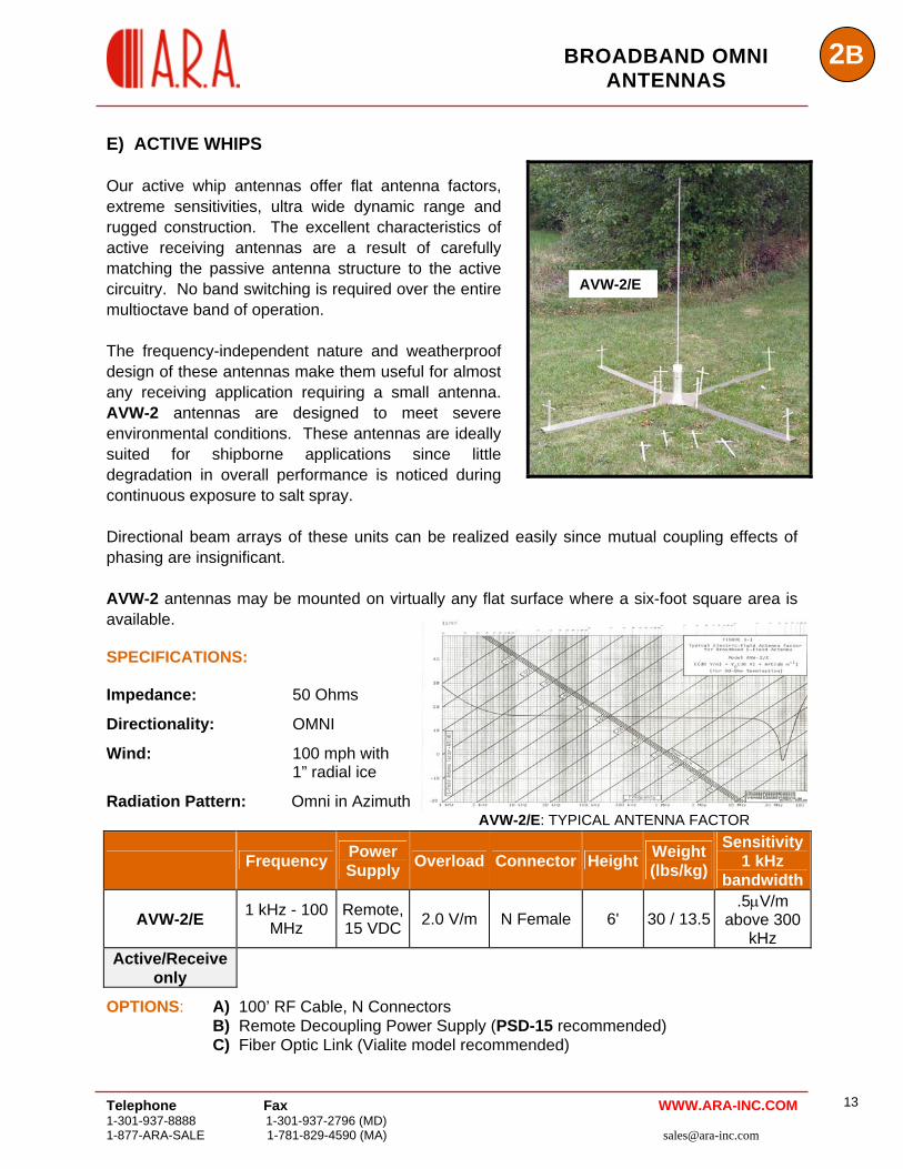
E) ACTIVE WHIPS Our active whip antennas offer flat antenna factors, extreme sensitivities, ultra wide dynamic range and rugged construction. The excellent characteristics of active receiving antennas are a result of carefully matching the passive antenna structure to the active circuitry. No band switching is required over the entire multioctave band of operation. The frequency-independent nature and weatherproof design of these antennas make them useful for almost any receiving application requiring a small antenna. AVW-2 antennas are designed to meet severe environmental conditions. These antennas are ideally suited for shipborne applications since little degradation in overall performance is noticed during continuous exposure to salt spray.
AVW-2/E
Directional beam arrays of these units can be realized easily since mutual coupling effects of phasing are insignificant. AVW-2 antennas may be mounted on virtually any flat surface where a six-foot square area is available. SPECIFICATIONS: Impedance: 50 Ohms
Directionality: OMNI
Wind: 100 mph with 1” radial ice
Radiation Pattern: Omni in Azimuth
Frequency Power Supply Overload Connector Height Weight
(lbs/kg)
Sensitivity 1 kHz
bandwidth
AVW-2/E 1 kHz - 100 MHz
Remote, 15 VDC 2.0 V/m N Female 6' 30 / 13.5
.5μV/m above 300
kHz Active/Receive
only
AVW-2/E: TYPICAL ANTENNA FACTOR
OPTIONS: A) 100’ RF Cable, N Connectors B) Remote Decoupling Power Supply (PSD-15 recommended)
C) Fiber Optic Link (Vialite model recommended)
2C BROADBAND AND
HIGH GAIN OMNIS
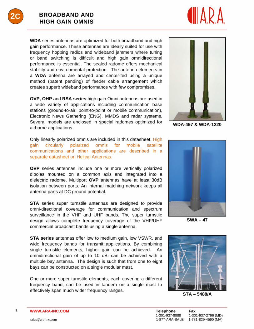
WDA series antennas are optimized for both broadband and high gain performance. These antennas are ideally suited for use with frequency hopping radios and wideband jammers where tuning or band switching is difficult and high gain omnidirectional performance is essential. The sealed radome offers mechanical stability and environmental protection. The antenna elements in a WDA antenna are arrayed and center-fed using a unique method (patent pending) of feeder cable arrangement which creates superb wideband performance with few compromises. OVP, OHP and RSA series high gain Omni antennas are used in a wide variety of applications including communication base stations (ground-to-air, point-to-point or mobile communication), Electronic News Gathering (ENG), MMDS and radar systems. Several models are enclosed in special radomes optimized for airborne applications. Only linearly polarized omnis are included in this datasheet. High gain circularly polarized omnis for mobile satellite communications and other applications are described in a separate datasheet on Helical Antennas. OVP series antennas include one or more vertically polarized dipoles mounted on a common axis and integrated into a dielectric radome. Multiport OVP antennas have at least 30dB isolation between ports. An internal matching network keeps all antenna parts at DC ground potential. STA series super turnstile antennas are designed to provide omni-directional coverage for communication and spectrum surveillance in the VHF and UHF bands. The super turnstile design allows complete frequency coverage of the VHF/UHF commercial broadcast bands using a single antenna. STA series antennas offer low to medium gain, low VSWR, and wide frequency bands for transmit applications. By combining single turnstile elements, higher gain can be achieved. An omnidirectional gain of up to 10 dBi can be achieved with a multiple bay antenna. The design is such that from one to eight bays can be constructed on a single modular mast. One or more super turnstile elements, each covering a different frequency band, can be used in tandem on a single mast to effectively span much wider frequency ranges.
WDA-497 & WDA-1220
SWA – 47
STA – 5488/A
Telephone Fax
1-301-937-8888 1-301-937-2796 (MD) [email protected] 1-877-ARA-SALE 1-781-829-4590 (MA)
1 WWW.ARA-INC.COM
2CBROADBAND AND
HIGH GAIN OMNIS
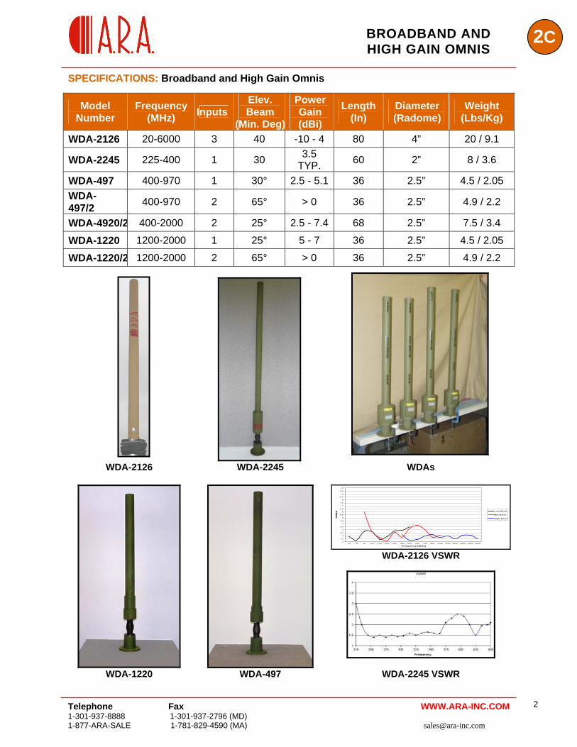
SPECIFICATIONS: Broadband and High Gain Omnis
Model Number
Frequency (MHz) Inputs
Elev. Beam
(Min. Deg)
Power Gain (dBi)
Length (In)
Diameter (Radome)
Weight (Lbs/Kg)
WDA-2126 20-6000 3 40 -10 - 4 80 4” 20 / 9.1
WDA-2245 225-400 1 30 3.5 TYP. 60 2” 8 / 3.6
WDA-497 400-970 1 30° 2.5 - 5.1 36 2.5” 4.5 / 2.05 WDA-497/2 400-970 2 65° > 0 36 2.5” 4.9 / 2.2
WDA-4920/2 400-2000 2 25° 2.5 - 7.4 68 2.5” 7.5 / 3.4
WDA-1220 1200-2000 1 25° 5 - 7 36 2.5” 4.5 / 2.05
WDA-1220/2 1200-2000 2 65° > 0 36 2.5” 4.9 / 2.2
WDA-2126 WDA-2245 WDAs
1
1.5
2
2.5
3
3.5
4
4.5
5
5.5
6
6.5
7
7.5
8
8.5
9
9.5
10
10 20 50 120 150 200 300 400 500 600 700 800 1000 2000 3000 4000 5000 6000
Low-Band
VSWR [:1]
Mid-Band
High-Band
Frequency [MHz]
WDA-2126 VSWR
WDA-1220 WDA-497 WDA-2245 VSWR
Telephone Fax 1-301-937-8888 1-301-937-2796 (MD) 1-877-ARA-SALE 1-781-829-4590 (MA) [email protected]
2 WWW.ARA-INC.COM
2C BROADBAND AND
HIGH GAIN OMNIS
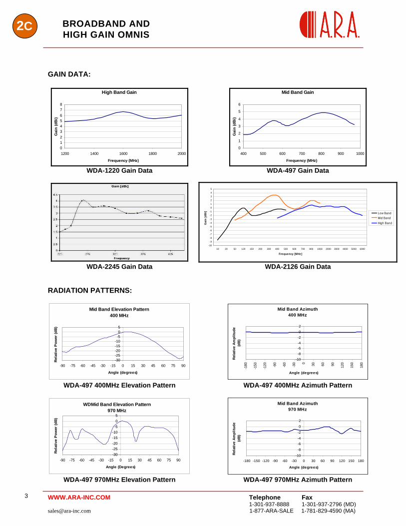
GAIN DATA:
High Band Gain
012345678
1200 1400 1600 1800 2000
Frequency (MHz)
Gai
n (d
Bi)
Mid Band Gain
0
1
2
3
4
5
6
400 500 600 700 800 900 1000
Frequency (MHz)
Gai
n (d
Bi)
WDA-1220 Gain Data WDA-497 Gain Data
-10-9-8-7-6-5-4-3-2-1012345
10 20 50 120 150 200 300 400 500 600 700 800 1000 2000 3000 4000 5000 6000
Frequency [MHz]
Gai
n [d
Bi]
Low BandMid BandHigh Band
WDA-2245 Gain Data WDA-2126 Gain Data
RADIATION PATTERNS:
Mid Band Elevation Pattern400 MHz
-30-25-20-15-10-505
-90 -75 -60 -45 -30 -15 0 15 30 45 60 75 90
Angle (degrees)
Rela
tive
Pow
er (d
B)
Mid Band Azimuth400 MHz
-10-8-6-4-202
-180
-150
-120 -90
-60
-30 0 30 60 90 120
150
180
Angle (degrees)
Rel
ativ
e A
mpl
itude
(d
B)
WDA-497 400MHz Elevation Pattern WDA-497 400MHz Azimuth Pattern
WDMid Band Elevation Pattern
970 MHz
-30-25-20-15-10-505
-90 -75 -60 -45 -30 -15 0 15 30 45 60 75 90
Angle (Degrees)
Rel
ativ
e Po
wer
(dB)
Mid Band Azimuth970 MHz
-10-8-6-4-202
-180 -150 -120 -90 -60 -30 0 30 60 90 120 150 180
Angle (degrees)
Rel
ativ
e A
mpl
itude
(d
B)
WDA-497 970MHz Elevation Pattern WDA-497 970MHz Azimuth Pattern
Telephone Fax
1-301-937-8888 1-301-937-2796 (MD) [email protected] 1-877-ARA-SALE 1-781-829-4590 (MA)
3 WWW.ARA-INC.COM
2CBROADBAND AND
HIGH GAIN OMNIS
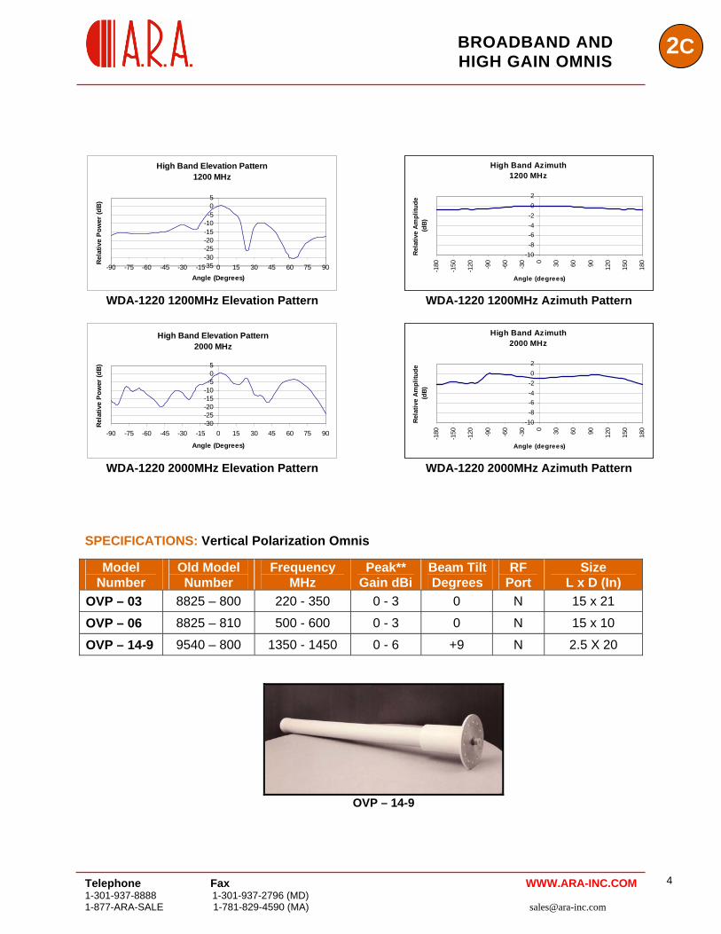
High Band Elevation Pattern1200 MHz
-35-30-25-20-15-10-505
-90 -75 -60 -45 -30 -15 0 15 30 45 60 75 90Angle (Degrees)
Rela
tive
Pow
er (d
B)
High Band Azimuth1200 MHz
-10-8-6-4-202
-180
-150
-120 -90
-60
-30 0 30 60 90 120
150
180
Angle (degrees)
Rel
ativ
e Am
plitu
de
(dB)
WDA-1220 1200MHz Elevation Pattern WDA-1220 1200MHz Azimuth Pattern
High Band Elevation Pattern
2000 MHz
-30-25-20-15-10-505
-90 -75 -60 -45 -30 -15 0 15 30 45 60 75 90
Angle (Degrees)
Rela
tive
Pow
er (d
B)
High Band Azimuth2000 MHz
-10-8-6-4-202
-180
-150
-120 -90
-60
-30 0 30 60 90 120
150
180
Angle (degrees)
Rel
ativ
e Am
plitu
de
(dB)
WDA-1220 2000MHz Elevation Pattern WDA-1220 2000MHz Azimuth Pattern
SPECIFICATIONS: Vertical Polarization Omnis
Model Number
Old Model Number
Frequency MHz
Peak** Gain dBi
Beam Tilt Degrees
RF Port
Size L x D (In)
OVP – 03 8825 – 800 220 - 350 0 - 3 0 N 15 x 21
OVP – 06 8825 – 810 500 - 600 0 - 3 0 N 15 x 10
OVP – 14-9 9540 – 800 1350 - 1450 0 - 6 +9 N 2.5 X 20
OVP – 14-9
Telephone Fax 1-301-937-8888 1-301-937-2796 (MD) 1-877-ARA-SALE 1-781-829-4590 (MA) [email protected]
4 WWW.ARA-INC.COM
2C BROADBAND AND
HIGH GAIN OMNIS
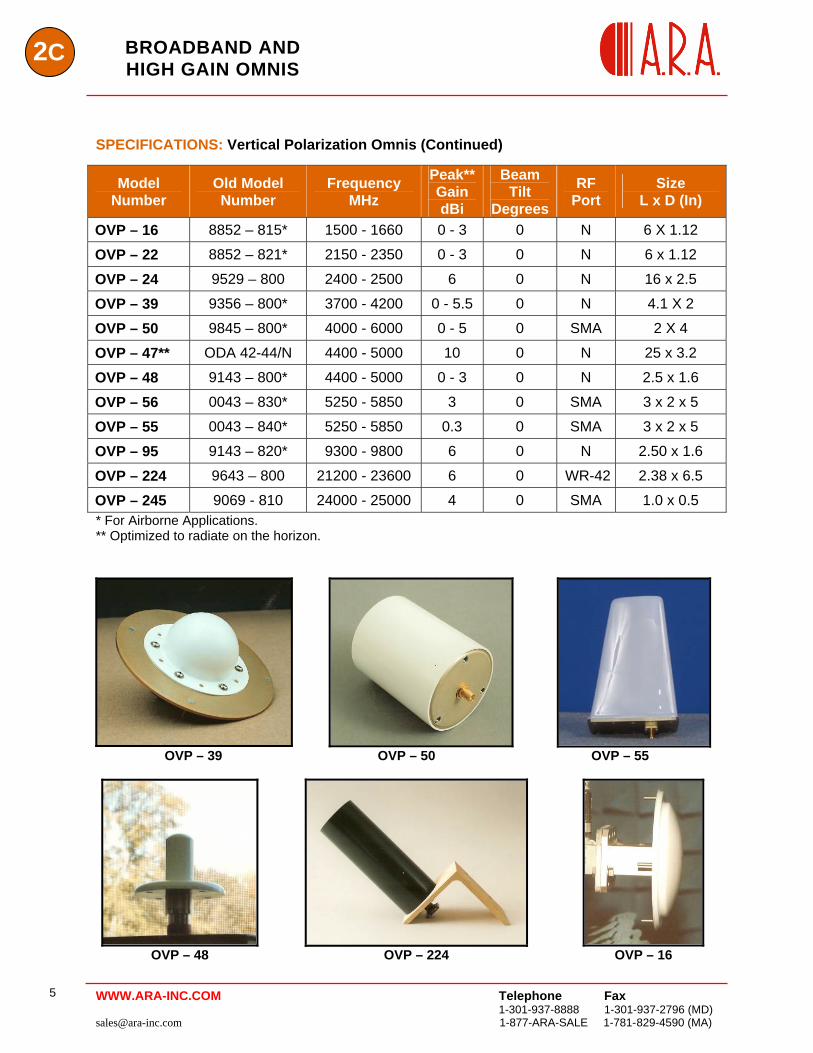
SPECIFICATIONS: Vertical Polarization Omnis (Continued)
Model Number
Old Model Number
Frequency MHz
Peak**Gain dBi
Beam Tilt
Degrees
RF Port
Size L x D (In)
OVP – 16 8852 – 815* 1500 - 1660 0 - 3 0 N 6 X 1.12
OVP – 22 8852 – 821* 2150 - 2350 0 - 3 0 N 6 x 1.12
OVP – 24 9529 – 800 2400 - 2500 6 0 N 16 x 2.5
OVP – 39 9356 – 800* 3700 - 4200 0 - 5.5 0 N 4.1 X 2
OVP – 50 9845 – 800* 4000 - 6000 0 - 5 0 SMA 2 X 4
OVP – 47** ODA 42-44/N 4400 - 5000 10 0 N 25 x 3.2
OVP – 48 9143 – 800* 4400 - 5000 0 - 3 0 N 2.5 x 1.6
OVP – 56 0043 – 830* 5250 - 5850 3 0 SMA 3 x 2 x 5
OVP – 55 0043 – 840* 5250 - 5850 0.3 0 SMA 3 x 2 x 5
OVP – 95 9143 – 820* 9300 - 9800 6 0 N 2.50 x 1.6
OVP – 224 9643 – 800 21200 - 23600 6 0 WR-42 2.38 x 6.5
OVP – 245 9069 - 810 24000 - 25000 4 0 SMA 1.0 x 0.5 * For Airborne Applications. ** Optimized to radiate on the horizon.
OVP – 39 OVP – 50 OVP – 55
OVP – 48 OVP – 224 OVP – 16
Telephone Fax
1-301-937-8888 1-301-937-2796 (MD) [email protected] 1-877-ARA-SALE 1-781-829-4590 (MA)
5 WWW.ARA-INC.COM
2CBROADBAND AND
HIGH GAIN OMNIS
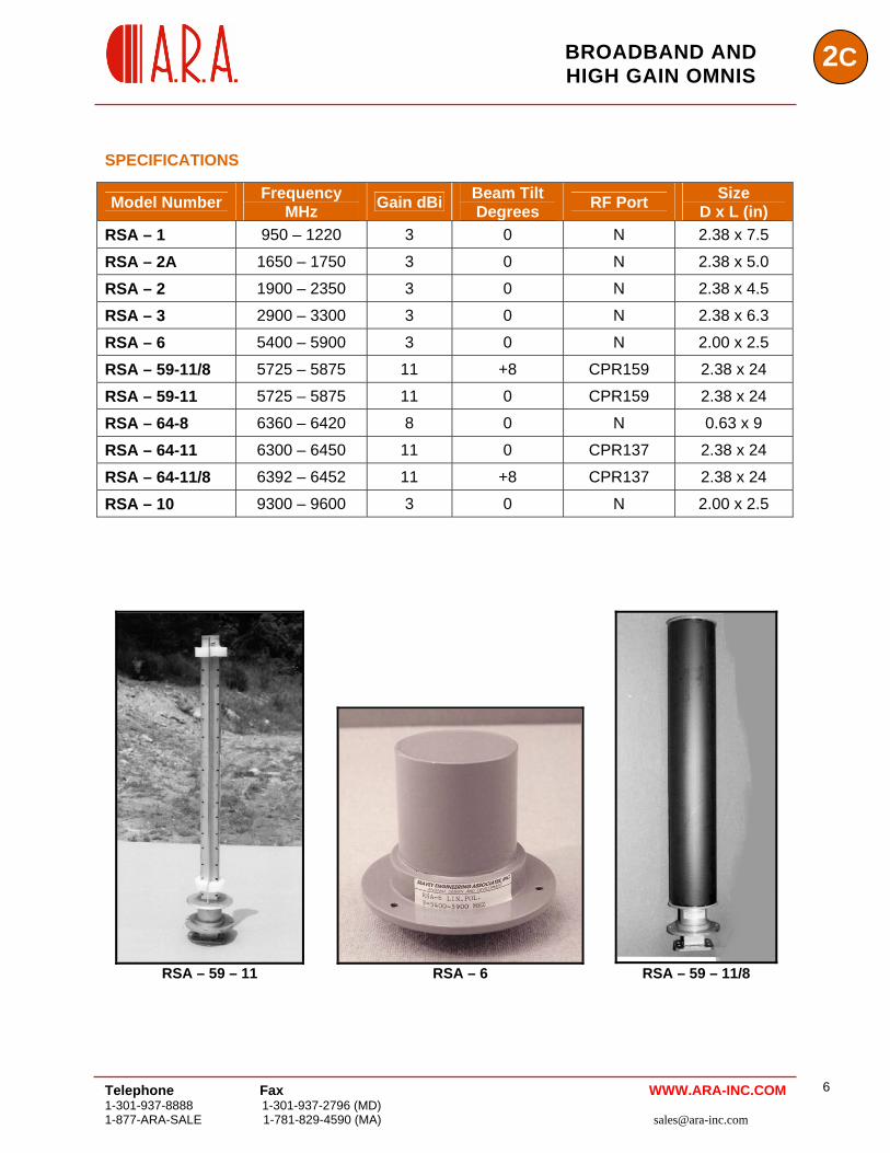
SPECIFICATIONS
Model Number Frequency MHz Gain dBi Beam Tilt
Degrees RF Port Size D x L (in)
RSA – 1 950 – 1220 3 0 N 2.38 x 7.5
RSA – 2A 1650 – 1750 3 0 N 2.38 x 5.0
RSA – 2 1900 – 2350 3 0 N 2.38 x 4.5
RSA – 3 2900 – 3300 3 0 N 2.38 x 6.3
RSA – 6 5400 – 5900 3 0 N 2.00 x 2.5
RSA – 59-11/8 5725 – 5875 11 +8 CPR159 2.38 x 24
RSA – 59-11 5725 – 5875 11 0 CPR159 2.38 x 24
RSA – 64-8 6360 – 6420 8 0 N 0.63 x 9
RSA – 64-11 6300 – 6450 11 0 CPR137 2.38 x 24
RSA – 64-11/8 6392 – 6452 11 +8 CPR137 2.38 x 24
RSA – 10 9300 – 9600 3 0 N 2.00 x 2.5
RSA – 59 – 11 RSA – 6 RSA – 59 – 11/8
Telephone Fax 1-301-937-8888 1-301-937-2796 (MD) 1-877-ARA-SALE 1-781-829-4590 (MA) [email protected]
6 WWW.ARA-INC.COM
Telephone Fax
1-301-937-8888 1-301-937-2796 (MD) [email protected] 1-877-ARA-SALE 1-781-829-4590 (MA)
7
2C BROADBAND AND HIGH GAIN OMNIS
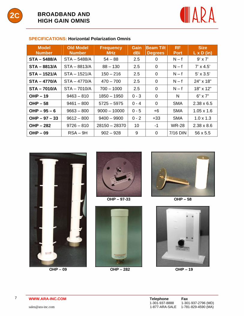
SPECIFICATIONS: Horizontal Polarization Omnis
Model Number
Old Model Number
Frequency MHz
Gain dBi
Beam Tilt Degrees
RF Port
Size L x D (in)
STA – 5488/A STA – 5488/A 54 – 88 2.5 0 N – f 9’ x 7’
STA – 8813/A STA – 8813/A 88 – 130 2.5 0 N – f 7’ x 4.5’
STA – 1521/A STA – 1521/A 150 – 216 2.5 0 N – f 5’ x 3.5’
STA – 4770/A STA – 4770/A 470 – 700 2.5 0 N – f 24” x 18”
STA – 7010/A STA – 7010/A 700 – 1000 2.5 0 N – f 18” x 12”
OHP – 19 9463 – 810 1850 – 1950 0 - 3 0 N 6” x 7”
OHP – 58 9461 – 800 5725 – 5975 0 - 4 0 SMA 2.38 x 6.5
OHP – 95 – 6 9663 – 800 9000 – 10000 0 - 5 +6 SMA 1.05 x 1.6
OHP – 97 – 33 9612 – 800 9400 – 9900 0 - 2 +33 SMA 1.0 x 1.3
OHP – 282 9726 – 810 28150 – 28370 10 -1 WR-28 2.38 x 8.6
OHP – 09 RSA – 9H 902 – 928 9 0 7/16 DIN 56 x 5.5
OHP – 97-33 OHP – 58
OHP – 09 OHP – 282 OHP – 19
WWW.ARA-INC.COM