Embed Size (px)
Citation preview
DOE UTSR Program Highlights: Advanced TBCs for gas turbine engines
Advanced Thermal Barrier Coatings for Operation in High Hydrogen Content Gas Turbines
PI : Sanjay Sampath
Contributors: Prof. C. M. Weyant, Dr. G. Dwivedi, V. Viswanathan
Dwivedi et al., JACerS, DOI: 10.1111/jace.13021
Viswanathan et al., JACerS, DOI: 10.1111/jace.13033
Dwivedi et al., JTST, DOI: 10.1007/S11666-014-0196-9
Viswanathan et al., JACerS, Under Review
DOE NETL UTSR
Contract #DE-FE0004771, 2010-2014
Program Manager: Dr. Briggs while
Research Highlights
Dwivedi et al., Adv. Mater. Process, 2013, 8(2), 49
Publication list
DOE UTSR Program Highlights: Advanced TBCs for gas turbine engines
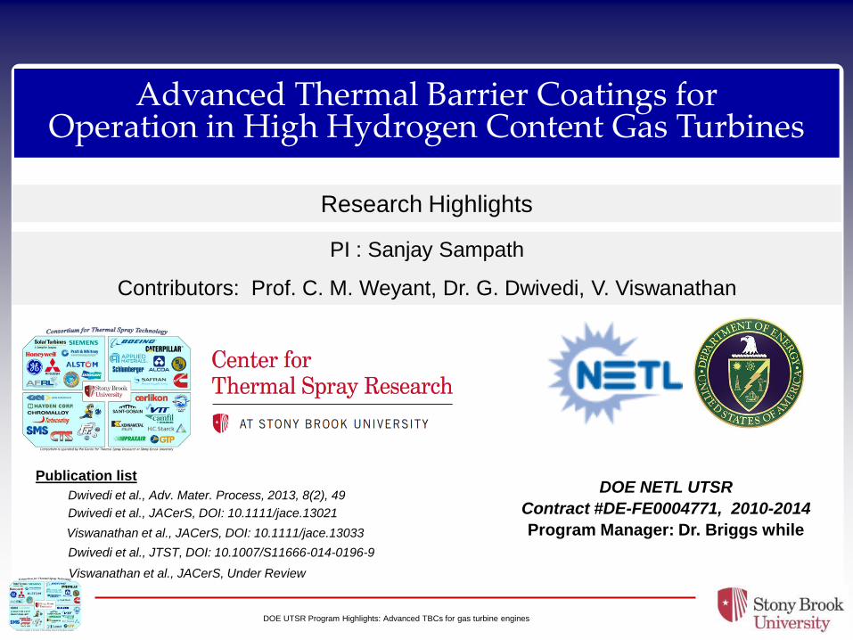
Multifunctional requirements of TBCs requires Multilayered architecture
Erosion, FOD, CMAS/Ash
Low-K material, Porosity,
Lower sintering rate
Remains complaint
Compatibility with Bondcoat
Mostly traditional TBC, High
toughness
Adequate roughness,
oxidation resistant (dense),
environmental effects
2
Multilayer,
Multifunctional
Coating
Solution
Challenges associated with
new gen TBCs
Layer-by-layer
optimization of
multilayered
TBCs is naturally
suited for Thermal
Spray
DOE UTSR Program Highlights: Advanced TBCs for gas turbine engines
Bond coat processing and performance 3
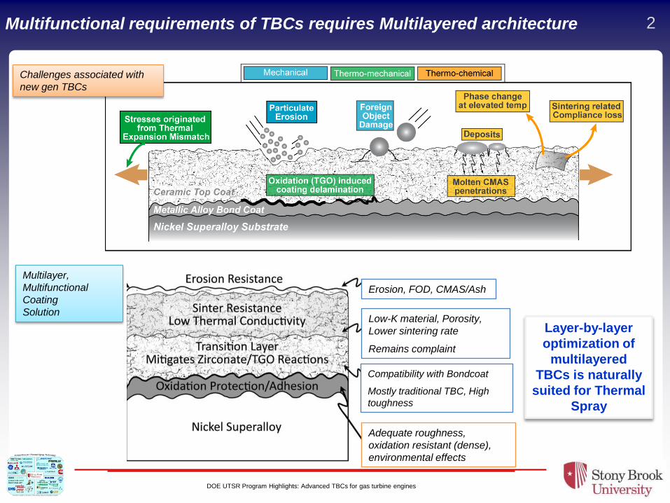
Process selection and mapping strategy for
the density and oxidation optimization Initial performance evaluation
with HVOF bond coats
Stony Brook BC Commercial BC
Rene’ 80 substrate
300µm APS 8YSZ
FCT: 1100oC, 24 hrs cycle
Prior work conducted at Stony Brook has explored the process-property
relationship of bond-coat material deposited using Atmospheric plasma
Spray and High Velocity Oxy-fuel (HVOF) processes.
The selection of HVOF process was to obtain dense bond-coat
microstructure with minimum oxide inclusion (WOKA and DJ2700 in the
above figure).
Such coatings offer requisite oxidation resistance to the substrate.
For material selection, concurrent study was conducted at ORNL (coating
prepared by Stony Brook), on two different bond-coat chemistries- SM
AMDRY 386-2 (NiCoCrAlYHfSi) and SM XPT 449 (NiCoCrAlY). Results
suggested superior performance of AMDRY 386-2.
Therefore, the bond-coat study at Stony Brook, focused on the same
(AMDRY 386-2) material. The coating was deposited using liquid fuel
HVOF process.
Stony Brook’s BC
Poor adhesion
Commercial BC
Good adhesion
Initial results exhibited
significantly poor life of
TBC sprayed on Stony
Brook’s bond-coat,
compared to those sprayed
on commercially obtained
bond-coat.
Initial observations on failed specimens indicated that the poor FCT life in
Stony Brook’s bond-coat specimen was primarily due to lower bond-coat
roughness.
Ra = 3-4 µm Ra = 9-10 µm
Photographs of failed specimens
20µm Substrate
AMDRY 386-4
(Coarse powder) Roughness
Ra = ~ 8 – 9 µm
AMDRY 386-2
(Fine powder)
Layer-1: Oxidation
resistant dense layer
Layer-2: Roughness improvement
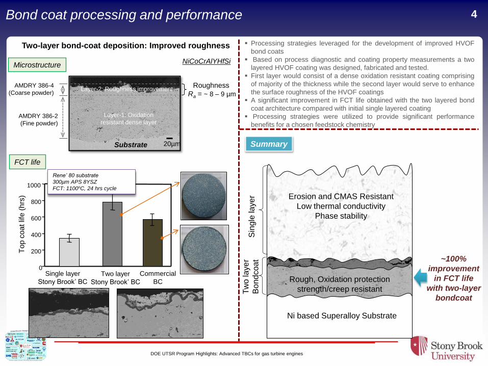
Two-layer bond-coat deposition: Improved roughness
NiCoCrAlYHfSi
DOE UTSR Program Highlights: Advanced TBCs for gas turbine engines
Bond coat processing and performance 4
NiCoCrAlYHfSi
Two-layer bond-coat deposition: Improved roughness
Microstructure
20µm Substrate
AMDRY 386-4
(Coarse powder) Roughness
Ra = ~ 8 – 9 µm
AMDRY 386-2
(Fine powder)
Layer-1: Oxidation
resistant dense layer
Layer-2: Roughness improvement
FCT life
0
200
400
600
800
1000
To
p c
oat lif
e (
hrs
)
Rene’ 80 substrate
300µm APS 8YSZ
FCT: 1100oC, 24 hrs cycle
Single layer
Stony Brook’ BC Two layer
Stony Brook’ BC
Commercial
BC
Ni based Superalloy Substrate
Tw
o laye
r
Bo
nd
coa
t
Rough, Oxidation protection
strength/creep resistant
Erosion and CMAS Resistant
Low thermal conductivity
Phase stability
Sin
gle
laye
r ~100%
improvement
in FCT life
with two-layer
bondcoat
Processing strategies leveraged for the development of improved HVOF
bond coats
Based on process diagnostic and coating property measurements a two
layered HVOF coating was designed, fabricated and tested.
First layer would consist of a dense oxidation resistant coating comprising
of majority of the thickness while the second layer would serve to enhance
the surface roughness of the HVOF coatings
A significant improvement in FCT life obtained with the two layered bond
coat architecture compared with initial single layered coating
Processing strategies were utilized to provide significant performance
benefits for a chosen feedstock chemistry
Summary

DOE UTSR Program Highlights: Advanced TBCs for gas turbine engines
5 Performance assessment of various APS YSZ architectures
D
50 µm 50 µm
DVC
unmolten
particles
vertical
cracks
A B
50 µm 50 µm
C
50 µm
interlamellar
pores
globular
pores microcracks
FC
T L
ife
(H
ou
rs)
0
200
400
600
800
1000
FCT Hours
FCT Hours: 784.0000
A B C D
Typical APS coatings
DVC
To
pco
at L
ife
(H
ou
rs)
Rene’ 80 substrate
Two layer Stony Brook’s BC
FCT: 1100oC, 24 hrs cycle
Five top coat architectures with decreasing porosity from A to DVC, were sprayed on
identical bond-coated superalloy substrates, and were subjected to FCT.
The FCT results indicated higher top coat life for coatings with lower porosity .
The measured elastic modulus and thermal conductivity of coatings also increases with
decreasing porosity.
The fracture toughness (measurement details are in next page) of coatings appears to be the
operating mechanism with higher toughness coatings resulting in higher FCT durability
0
10
20
30
40
50
60
0
1
2
3
4
Ela
stic M
odu
lus (
GP
a)
Fra
ctu
re T
oug
hne
ss (
MP
a
m)
0.0
0.2
0.4
0.6
0.8
1.0
1.2
1.4
1.6
1.8
Th
erm
al C
ond
uctivity (
W/m
K)
A B C D DVC*
FCT life of coatings is higher with higher fracture toughness coatings. However, these coatings also have higher thermal
conductivity, which is not desirable for TBCs.
The high fracture toughness requirement only seems to be at the bond-coat and top-coat interface. Can we design a
multilayer top-coat with low overall thermal conductivity and high toughness at the interface
100µm 100µm
As-deposited TBC Failed (~600 hrs)
DOE UTSR Program Highlights: Advanced TBCs for gas turbine engines
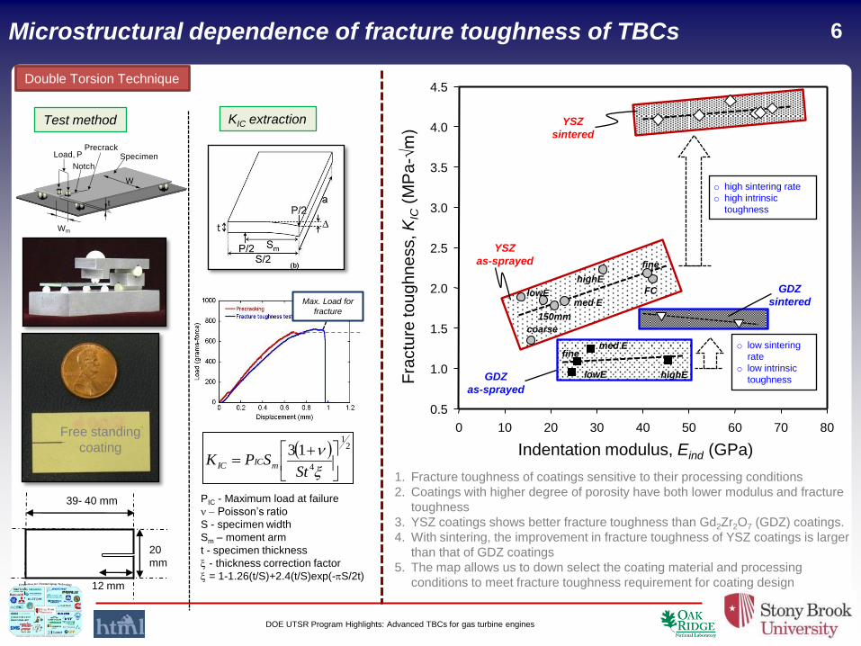
Microstructural dependence of fracture toughness of TBCs 6
GDZ
as-sprayed
YSZ
as-sprayed
GDZ
sintered
0 10 20 30 40 50 60 70 80
Indentation modulus, Eind (GPa)
0.5
1.0
1.5
2.0
2.5
3.0
3.5
4.0
4.5
Fra
ctu
re to
ug
hn
ess, K
IC (
MP
a-√
m)
YSZ
sintered
o high sintering rate
o high intrinsic
toughness
o low sintering
rate
o low intrinsic
toughness
FC
coarse
med E
highE
lowE
fine
150mm
med E
highE lowE
fine
PrecrackLoad, P Specimen
t
W
Wm
Notch
1. Fracture toughness of coatings sensitive to their processing conditions
2. Coatings with higher degree of porosity have both lower modulus and fracture
toughness
3. YSZ coatings shows better fracture toughness than Gd2Zr2O7 (GDZ) coatings.
4. With sintering, the improvement in fracture toughness of YSZ coatings is larger
than that of GDZ coatings
5. The map allows us to down select the coating material and processing
conditions to meet fracture toughness requirement for coating design 12 mm
39- 40 mm
20
mm
Free standing
coating
Max. Load for
fracture
21
4
13
StSPK mICIC
PIC - Maximum load at failure
- Poisson’s ratio
S - specimen width
Sm – moment arm
t - specimen thickness
- thickness correction factor
= 1-1.26(t/S)+2.4(t/S)exp(-pS/2t)
Test method KIC extraction
Double Torsion Technique
DOE UTSR Program Highlights: Advanced TBCs for gas turbine engines
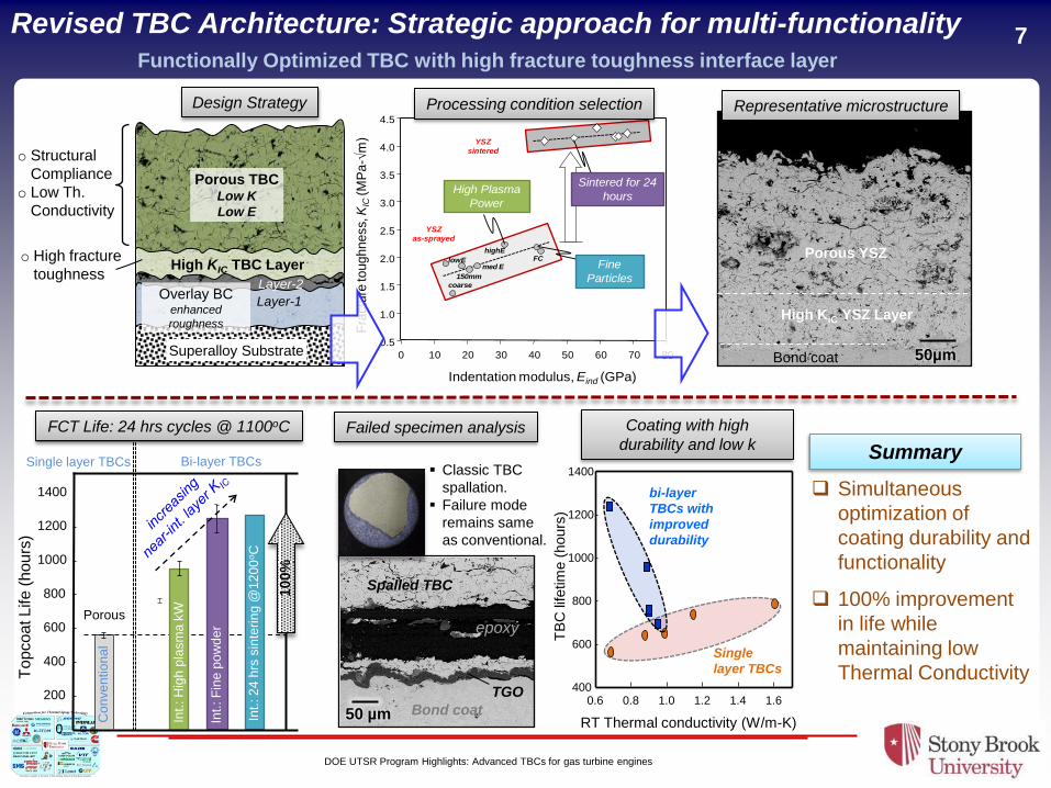
7 Revised TBC Architecture: Strategic approach for multi-functionality Functionally Optimized TBC with high fracture toughness interface layer
TB
C lifetim
e (
hours
)
RT Thermal conductivity (W/m-K)
0.6 0.8 1.0 1.2 1.4 1.6 400
600
800
1000
1200
1400
Single
layer TBCs
bi-layer
TBCs with
improved
durability
Superalloy Substrate
Overlay BC enhanced
roughness
Layer-1
Layer-2
High KIC TBC Layer
Porous TBC Low K
Low E
o Structural
Compliance
o Low Th.
Conductivity
o High fracture
toughness
Design Strategy
YSZ
as-sprayed
0 10 20 30 40 50 60 70 80
Indentation modulus, Eind (GPa)
0.5
1.0
1.5
2.0
2.5
3.0
3.5
4.0
4.5
Fra
ctu
re to
ug
hn
ess,
KIC
(MP
a-√
m) YSZ
sintered
FC
coarse
med E
highE
lowE
150mm
High Plasma
Power
Fine
Particles
Sintered for 24
hours
Processing condition selection
50µm
Representative microstructure
To
pco
at L
ife
(h
ou
rs)
0
200
400
600
800
1000
1200
1400
Co
nve
ntio
na
l
Single layer TBCs Bi-layer TBCs
Porous
100%
Int.
: H
igh
pla
sm
a k
W
Int.
: F
ine
po
wd
er
Int.
: 2
4 h
rs s
inte
rin
g @
12
00
oC
High KIC YSZ Layer
Porous YSZ
Bond coat
FCT Life: 24 hrs cycles @ 1100oC Failed specimen analysis
50 µm
epoxy
Bond coat
Spalled TBC
TGO
Classic TBC
spallation.
Failure mode
remains same
as conventional.
Coating with high
durability and low k
Simultaneous
optimization of
coating durability and
functionality
100% improvement
in life while
maintaining low
Thermal Conductivity
Summary
DOE UTSR Program Highlights: Advanced TBCs for gas turbine engines
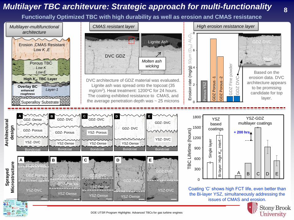
8
Superalloy Substrate
Layer-1
Layer-2
High KIC TBC Layer
Erosion ,CMAS Resistant
Low K ,E
Overlay BC enhanced
roughness
Porous TBC Low K
Low E
GDZ- DVC
Bondcoat
GDZ- Porous
YSZ-Dense
GDZ- DVC
Bondcoat
YSZ-Dense
GDZ- DVC
Bondcoat
YSZ- Porous
YSZ-Dense
GDZ- DVC
Bondcoat
YSZ- DVC
B D C E GDZ- Dense
Bondcoat
GDZ- Porous
YSZ- DVC
A
YSZ-DVC
GDZ-DVC
E
YSZ-Dense
YSZ-Porous
GDZ-DVC
C
YSZ-Dense
GDZ-DVC
D
YSZ-Dense
GDZ-Porous
GDZ-DVC
B
YSZ-DVC
GDZ-Porous
GDZ-Dense
A
0
300
600
900
1200
1500
1800
Sin
gle
laye
r
TB
C L
ife
tim
e (
hou
rs)
YSZ
based
coatings
YSZ-GDZ
multilayer coatings
A D C E B Bi-
laye
r: H
igh
KIC
in
terf
.
+ 200 hrs
Arc
hit
ectu
ral
des
ign
S
pra
ye
d
Mic
ros
tru
ctu
re
Molten ash
wicking
DVC GDZ
Lignite Ash
DVC architecture of GDZ material was evaluated.
Lignite ash was spread onto the topcoat (35
mg/cm2). Heat treatment: 1200oC for 24 hours.
The coating exhibited resistance to CMAS, and
the average penetration depth was ~ 25 microns
GD
Z D
VC
GD
Z F
ine p
ow
der
0
2
4
6
8
GD
Z P
oro
us -
1
GD
Z P
oro
us -
2
Po
rou
s Y
SZ
Ero
sio
n r
ate
(m
g/g
), 5
0µ
m (
D50)
Al 2
O3
50µm
GDZ DVC
Based on the
erosion data. DVC
architecture appears
to be promising
candidate for top
layer.
Multilayer TBC architevure: Strategic approach for multi-functionality Functionally Optimized TBC with high durability as well as erosion and CMAS resistance
Coating ‘C’ shows high FCT life, even better than
the Bi-layer YSZ, simultaneously addressing the
issues of CMAS and erosion.
High erosion resistance layer CMAS resistant layer Multilayer-multifunctional
architecture
DOE UTSR Program Highlights: Advanced TBCs for gas turbine engines
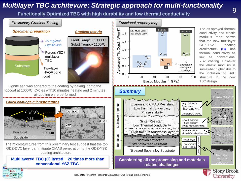
0 20 40 60 80 100 0.6
0.8
1.0
1.2
1.4
1.6
Elastic Modulus ( GPa )
B
C
D
E
Engineered
Multilayered
coatings
As-s
pra
yed T
h. C
ond. (W
/m-K
)
ML
ML DVCs SL DVCs
A
S1 S2
GDZ
YSZ
ML: Multi Layer
SL: Single Layer
P-G
P-Y
Front Temp: ~ 1300oC
Subst Temp:~ 1100oC
Two-layer
HVOF bond
coat
Porous YSZ /
multilayer
TBC
35 mg/cm2
Lignite Ash
Substrate
100 um Bondcoat
YSZ
Gd2Zr2O7
`
Substrate
YSZ
Gd2Zr2O7
DVC
Multilayered TBC (C) lasted ~ 20 times more than
conventional YSZ TBC.
Lignite ash was adhered to the coating by baking it onto the
topcoat at 1000oC. Cycles with10 minutes heating and 2 minutes
air cooling were performed
Preliminary Gradient Testing
Multilayer TBC architevure: Strategic approach for multi-functionality Functionally Optimized TBC with high durability and low thermal conductivity
Specimen preparation Gradient test rig
Failed coatings microstructures
The microsturctures from this preliminary test suggest that the top
GDZ-DVC layer can mitigate CMAS penetration to the GDZ-YSZ
coating architecture.
The as-sprayed thermal
conductivity and elastic
modulus map shows
that the new multilayer
GDZ-YSZ coating
architecture (C) has
thermal conductivity as
low as conventional
YSZ coating. However
the elastic modulus is
somewhat higher due to
the inclusion of DVC
structure in the new
TBC design.
Functional property map
Ni based Superalloy Substrate
Mu
ltila
ye
r T
op
co
at
Bo
nd
co
at
Oxidation protection
strength/creep resistant
High fracture toughness layer
Sinter Resistant
Low Thermal conductivity
Erosion and CMAS Resistant
Low thermal conductivity
Phase stability
- e.g. Gd2Zr2O7
Pyrochlore
- High Y2O3-ZrO2.
Dense/DVC archit.
-Low K material
-Phase stability
sinter resistant comp.
- t‘ composition
- low defect density coat
Rough layer
Low porosity
oxid. Resist.
CoN
iCrA
lY (
+R
e)
Dense Gd2Zr2O7
Porous
YSZ/GDZ
Dense YSZ
Two layer
MCrAlY
bondcoat
Summary
Considering all the processing and materials
related challenges
9
DOE UTSR Program Highlights: Advanced TBCs for gas turbine engines
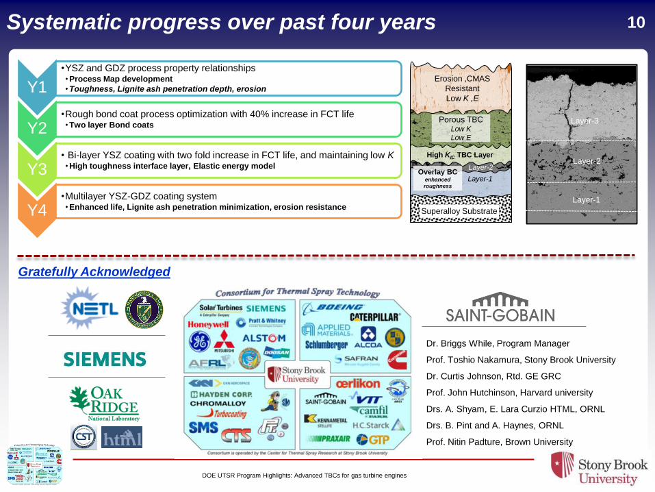
10
Y1
•YSZ and GDZ process property relationships • Process Map development
• Toughness, Lignite ash penetration depth, erosion
Y2 •Rough bond coat process optimization with 40% increase in FCT life • Two layer Bond coats
Y3 • Bi-layer YSZ coating with two fold increase in FCT life, and maintaining low K • High toughness interface layer, Elastic energy model
Y4 •Multilayer YSZ-GDZ coating system • Enhanced life, Lignite ash penetration minimization, erosion resistance
Systematic progress over past four years
Dr. Briggs While, Program Manager
Prof. Toshio Nakamura, Stony Brook University
Dr. Curtis Johnson, Rtd. GE GRC
Prof. John Hutchinson, Harvard university
Drs. A. Shyam, E. Lara Curzio HTML, ORNL
Drs. B. Pint and A. Haynes, ORNL
Prof. Nitin Padture, Brown University
Gratefully Acknowledged
Superalloy Substrate
Layer-1
Layer-2
High KIC TBC Layer
Erosion ,CMAS
Resistant
Low K ,E
Overlay BC enhanced
roughness
Porous TBC Low K
Low E
Layer-2
Layer-1
Layer-3