Embed Size (px)
Citation preview
Advanced Tutorial – Designing a Collimator for an LED Source
This tutorial demonstrates designing a collimator lens around an LED, utilizing both the reflector and lens design tools. It is a good idea to complete the beginner tutorials before attempting this advanced tutorial, since many of the more basic functions and concepts are not explained in this tutorial.
The collimator design parameters for this tutorial will be the following:
10° full beam angle (+/- 1°)
20mm maximum height
20mm maximum diameter
We will use the Lumileds Rebel as the source and acrylic as the lens material.
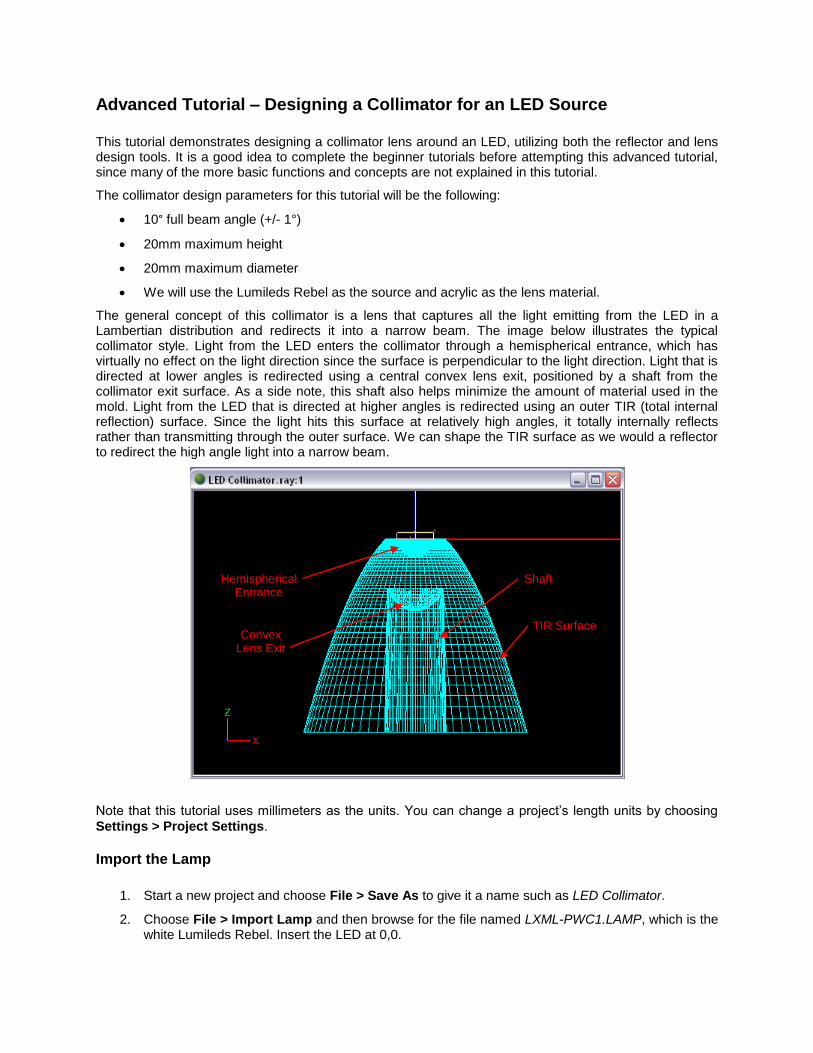
The general concept of this collimator is a lens that captures all the light emitting from the LED in a Lambertian distribution and redirects it into a narrow beam. The image below illustrates the typical collimator style. Light from the LED enters the collimator through a hemispherical entrance, which has virtually no effect on the light direction since the surface is perpendicular to the light direction. Light that is directed at lower angles is redirected using a central convex lens exit, positioned by a shaft from the collimator exit surface. As a side note, this shaft also helps minimize the amount of material used in the mold. Light from the LED that is directed at higher angles is redirected using an outer TIR (total internal reflection) surface. Since the light hits this surface at relatively high angles, it totally internally reflects rather than transmitting through the outer surface. We can shape the TIR surface as we would a reflector to redirect the high angle light into a narrow beam.
Note that this tutorial uses millimeters as the units. You can change a project’s length units by choosing
Settings > Project Settings.
Import the Lamp
1. Start a new project and choose File > Save As to give it a name such as LED Collimator.
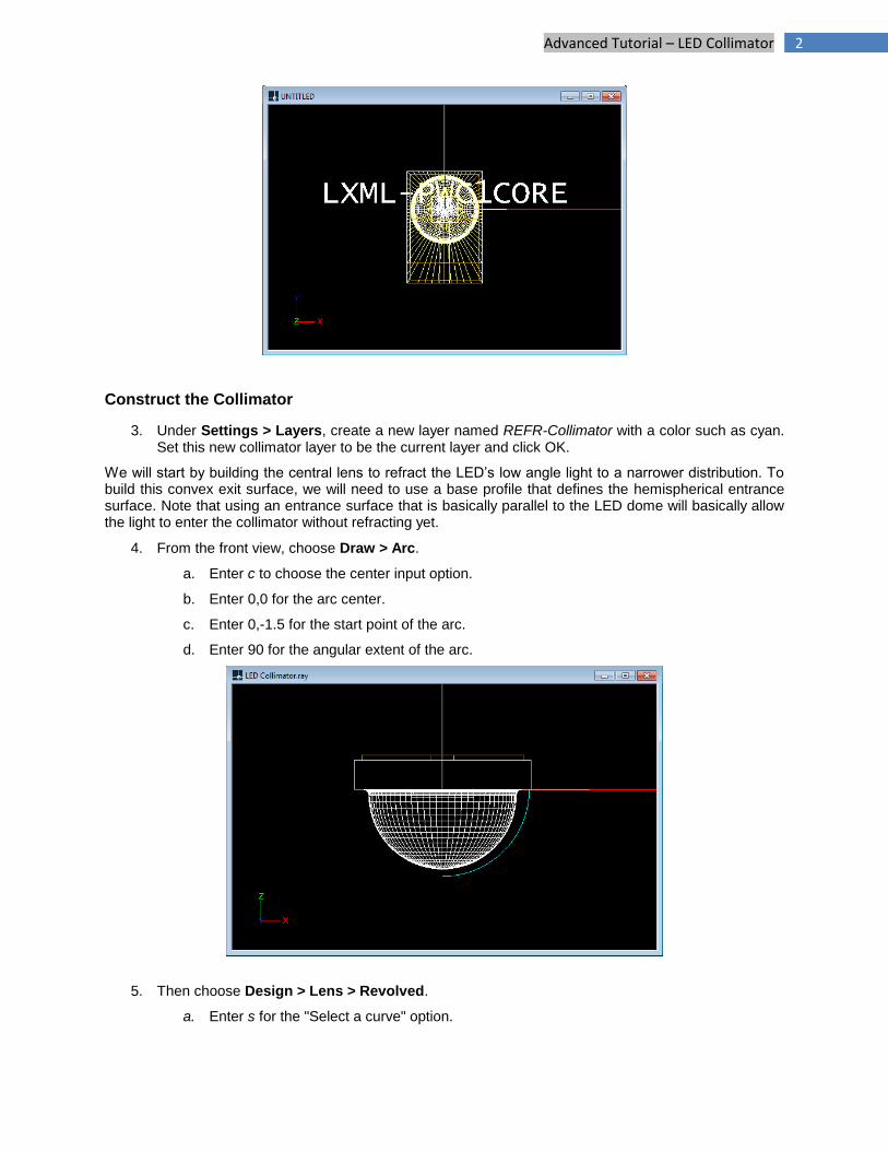
2. Choose File > Import Lamp and then browse for the file named LXML-PWC1.LAMP, which is the white Lumileds Rebel. Insert the LED at 0,0.
Hemispherical Entrance
Convex Lens Exit
Shaft
TIR Surface
2 Advanced Tutorial – LED Collimator
Construct the Collimator
3. Under Settings > Layers, create a new layer named REFR-Collimator with a color such as cyan. Set this new collimator layer to be the current layer and click OK.
We will start by building the central lens to refract the LED’s low angle light to a narrower distribution. To build this convex exit surface, we will need to use a base profile that defines the hemispherical entrance surface. Note that using an entrance surface that is basically parallel to the LED dome will basically allow the light to enter the collimator without refracting yet.
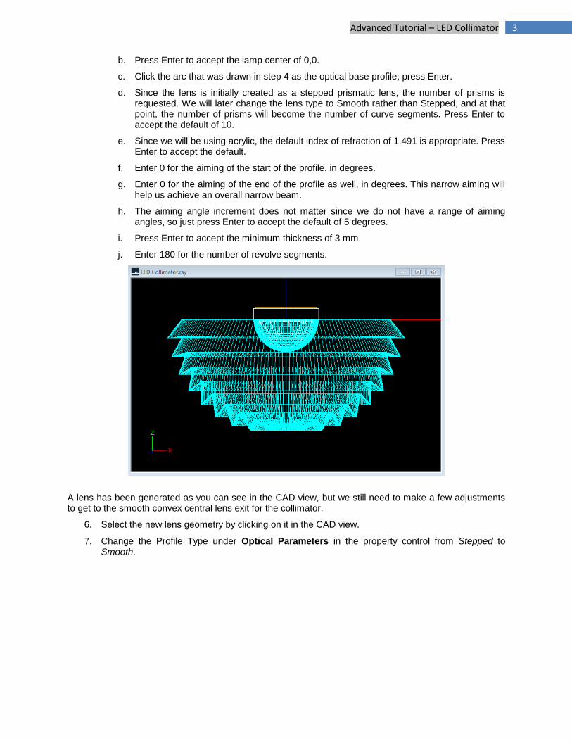
4. From the front view, choose Draw > Arc.
a. Enter c to choose the center input option.
b. Enter 0,0 for the arc center.
c. Enter 0,-1.5 for the start point of the arc.
d. Enter 90 for the angular extent of the arc.
5. Then choose Design > Lens > Revolved.
a. Enter s for the "Select a curve" option.
3 Advanced Tutorial – LED Collimator
b. Press Enter to accept the lamp center of 0,0.
c. Click the arc that was drawn in step 4 as the optical base profile; press Enter.
d. Since the lens is initially created as a stepped prismatic lens, the number of prisms is requested. We will later change the lens type to Smooth rather than Stepped, and at that point, the number of prisms will become the number of curve segments. Press Enter to accept the default of 10.
e. Since we will be using acrylic, the default index of refraction of 1.491 is appropriate. Press Enter to accept the default.
f. Enter 0 for the aiming of the start of the profile, in degrees.
g. Enter 0 for the aiming of the end of the profile as well, in degrees. This narrow aiming will help us achieve an overall narrow beam.
h. The aiming angle increment does not matter since we do not have a range of aiming angles, so just press Enter to accept the default of 5 degrees.
i. Press Enter to accept the minimum thickness of 3 mm.
j. Enter 180 for the number of revolve segments.
A lens has been generated as you can see in the CAD view, but we still need to make a few adjustments to get to the smooth convex central lens exit for the collimator.
6. Select the new lens geometry by clicking on it in the CAD view.
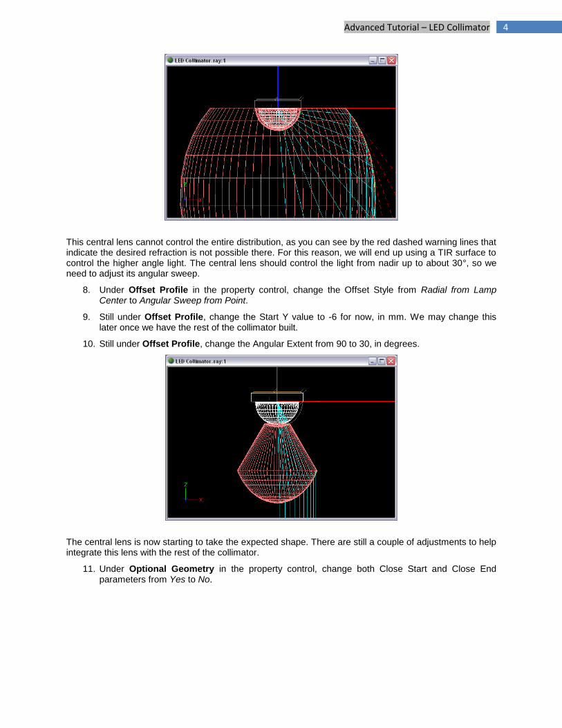
7. Change the Profile Type under Optical Parameters in the property control from Stepped to Smooth.
4 Advanced Tutorial – LED Collimator
This central lens cannot control the entire distribution, as you can see by the red dashed warning lines that indicate the desired refraction is not possible there. For this reason, we will end up using a TIR surface to control the higher angle light. The central lens should control the light from nadir up to about 30°, so we need to adjust its angular sweep.
8. Under Offset Profile in the property control, change the Offset Style from Radial from Lamp Center to Angular Sweep from Point.
9. Still under Offset Profile, change the Start Y value to -6 for now, in mm. We may change this later once we have the rest of the collimator built.
10. Still under Offset Profile, change the Angular Extent from 90 to 30, in degrees.
The central lens is now starting to take the expected shape. There are still a couple of adjustments to help integrate this lens with the rest of the collimator.
11. Under Optional Geometry in the property control, change both Close Start and Close End parameters from Yes to No.
5 Advanced Tutorial – LED Collimator
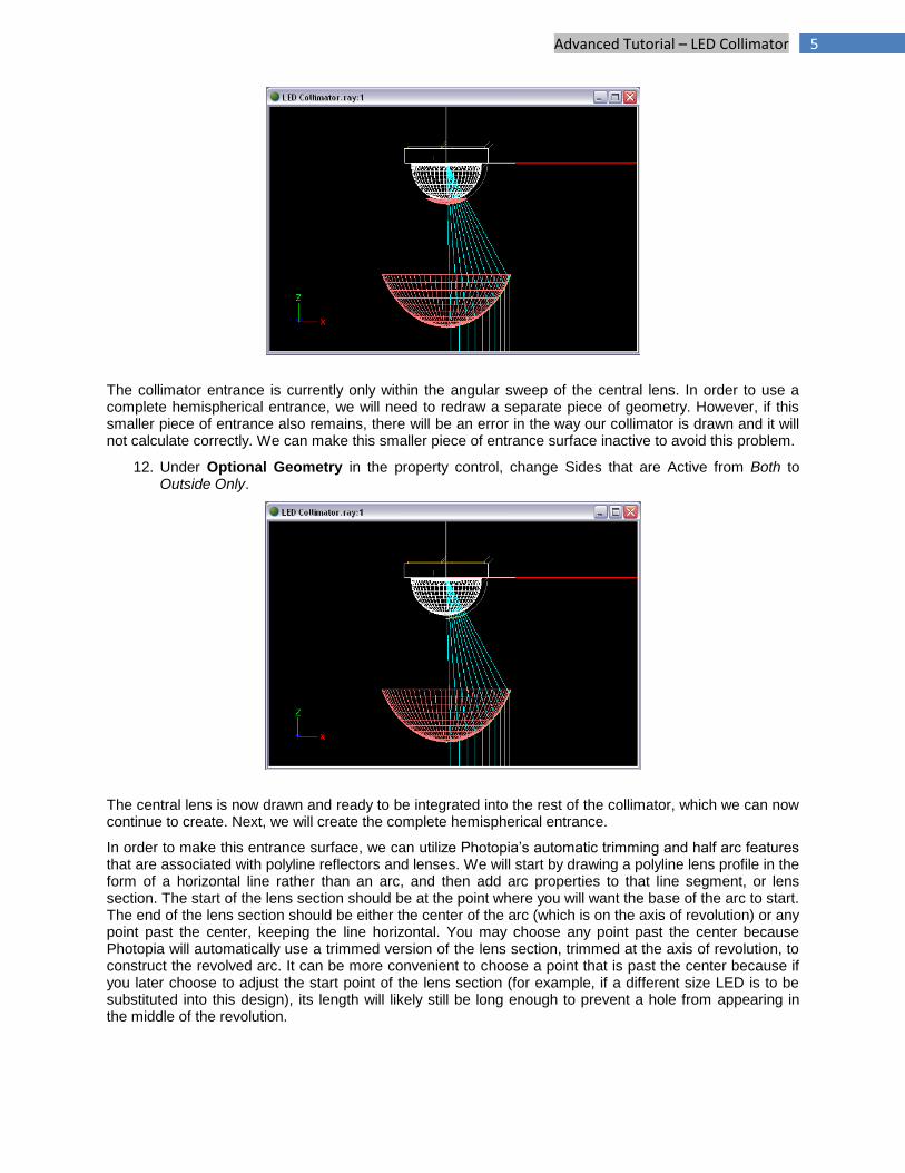
The collimator entrance is currently only within the angular sweep of the central lens. In order to use a complete hemispherical entrance, we will need to redraw a separate piece of geometry. However, if this smaller piece of entrance also remains, there will be an error in the way our collimator is drawn and it will not calculate correctly. We can make this smaller piece of entrance surface inactive to avoid this problem.
12. Under Optional Geometry in the property control, change Sides that are Active from Both to Outside Only.
The central lens is now drawn and ready to be integrated into the rest of the collimator, which we can now continue to create. Next, we will create the complete hemispherical entrance.
In order to make this entrance surface, we can utilize Photopia’s automatic trimming and half arc features that are associated with polyline reflectors and lenses. We will start by drawing a polyline lens profile in the form of a horizontal line rather than an arc, and then add arc properties to that line segment, or lens section. The start of the lens section should be at the point where you will want the base of the arc to start. The end of the lens section should be either the center of the arc (which is on the axis of revolution) or any point past the center, keeping the line horizontal. You may choose any point past the center because Photopia will automatically use a trimmed version of the lens section, trimmed at the axis of revolution, to construct the revolved arc. It can be more convenient to choose a point that is past the center because if you later choose to adjust the start point of the lens section (for example, if a different size LED is to be substituted into this design), its length will likely still be long enough to prevent a hole from appearing in the middle of the revolution.
6 Advanced Tutorial – LED Collimator
After drawing the polyline lens as a horizontal line, we will use Photopia’s half arc feature to turn the line into a revolved arc. You can make any section of a polyline lens into an arc by entering any non-zero value for the Angular Extent in Parametric Optical Design View. Doing so will, by default, create a full arc from the section’s start point to its end point (or trimmed end point if the axis of revolution is crossed) using the specified angular extent. For arc profiles that cross the axis of revolution, it is convenient to change the full arc into a half arc, which can be changed in Parametric Optical Design View for the end section of any polyline lens. A half arc that crosses the axis of revolution will always be constructed so that the revolved result is a full arc at the specified angular extent.
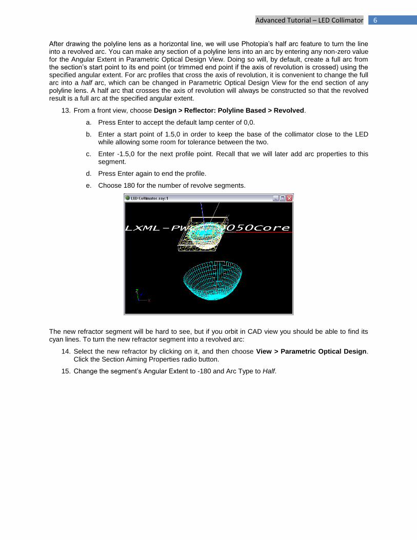
13. From a front view, choose Design > Reflector: Polyline Based > Revolved.
a. Press Enter to accept the default lamp center of 0,0.
b. Enter a start point of 1.5,0 in order to keep the base of the collimator close to the LED while allowing some room for tolerance between the two.
c. Enter -1.5,0 for the next profile point. Recall that we will later add arc properties to this segment.
d. Press Enter again to end the profile.
e. Choose 180 for the number of revolve segments.
The new refractor segment will be hard to see, but if you orbit in CAD view you should be able to find its cyan lines. To turn the new refractor segment into a revolved arc:
14. Select the new refractor by clicking on it, and then choose View > Parametric Optical Design. Click the Section Aiming Properties radio button.
15. Change the segment’s Angular Extent to -180 and Arc Type to Half.
7 Advanced Tutorial – LED Collimator
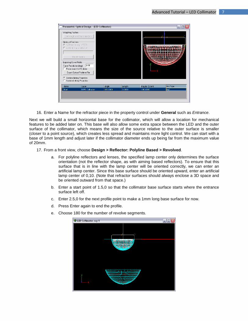
16. Enter a Name for the refractor piece in the property control under General such as Entrance.
Next we will build a small horizontal base for the collimator, which will allow a location for mechanical features to be added later on. This base will also allow some extra space between the LED and the outer surface of the collimator, which means the size of the source relative to the outer surface is smaller (closer to a point source), which creates less spread and maintains more light control. We can start with a base of 1mm length and adjust later if the collimator diameter ends up being far from the maximum value of 20mm.
17. From a front view, choose Design > Reflector: Polyline Based > Revolved.
a. For polyline reflectors and lenses, the specified lamp center only determines the surface orientation (not the reflector shape, as with aiming based reflectors). To ensure that this surface that is in line with the lamp center will be oriented correctly, we can enter an artificial lamp center. Since this base surface should be oriented upward, enter an artificial lamp center of 0,10. (Note that refractor surfaces should always enclose a 3D space and be oriented outward from that space.)
b. Enter a start point of 1.5,0 so that the collimator base surface starts where the entrance surface left off.
c. Enter 2.5,0 for the next profile point to make a 1mm long base surface for now.
d. Press Enter again to end the profile.
e. Choose 180 for the number of revolve segments.
8 Advanced Tutorial – LED Collimator
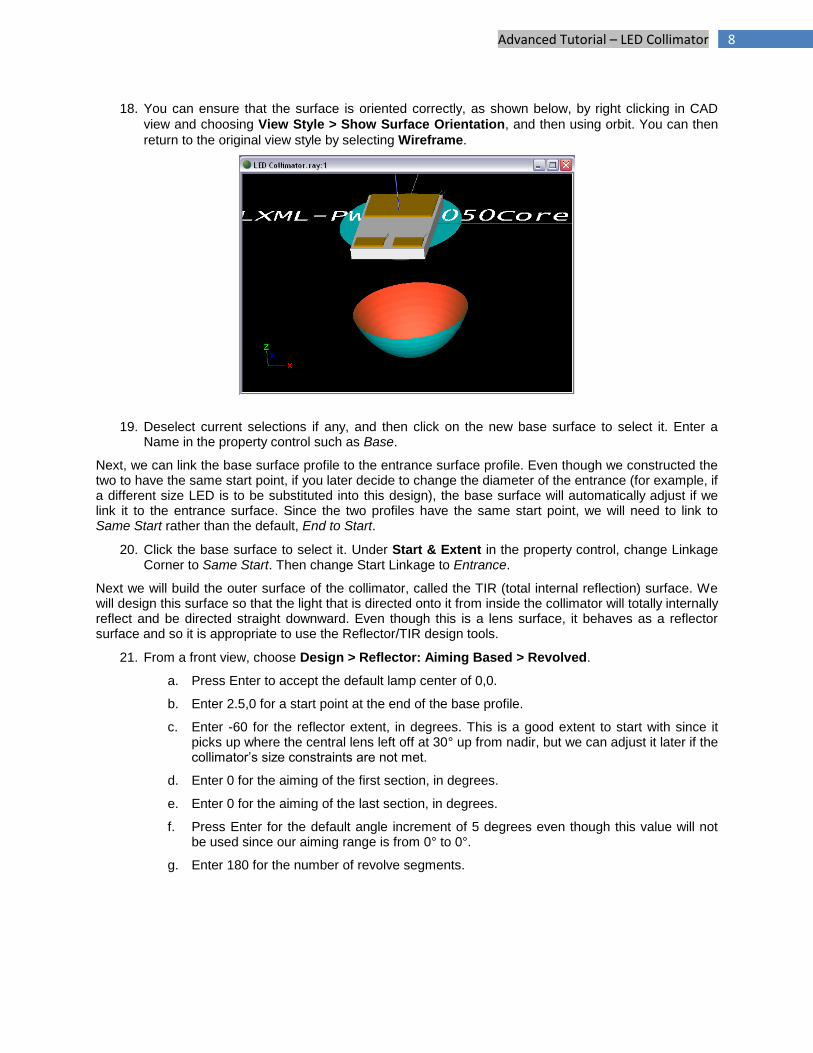
18. You can ensure that the surface is oriented correctly, as shown below, by right clicking in CAD
view and choosing View Style > Show Surface Orientation, and then using orbit. You can then
return to the original view style by selecting Wireframe.
19. Deselect current selections if any, and then click on the new base surface to select it. Enter a Name in the property control such as Base.
Next, we can link the base surface profile to the entrance surface profile. Even though we constructed the two to have the same start point, if you later decide to change the diameter of the entrance (for example, if a different size LED is to be substituted into this design), the base surface will automatically adjust if we link it to the entrance surface. Since the two profiles have the same start point, we will need to link to Same Start rather than the default, End to Start.
20. Click the base surface to select it. Under Start & Extent in the property control, change Linkage Corner to Same Start. Then change Start Linkage to Entrance.
Next we will build the outer surface of the collimator, called the TIR (total internal reflection) surface. We will design this surface so that the light that is directed onto it from inside the collimator will totally internally reflect and be directed straight downward. Even though this is a lens surface, it behaves as a reflector surface and so it is appropriate to use the Reflector/TIR design tools.
21. From a front view, choose Design > Reflector: Aiming Based > Revolved.
a. Press Enter to accept the default lamp center of 0,0.
b. Enter 2.5,0 for a start point at the end of the base profile.
c. Enter -60 for the reflector extent, in degrees. This is a good extent to start with since it picks up where the central lens left off at 30° up from nadir, but we can adjust it later if the collimator’s size constraints are not met.
d. Enter 0 for the aiming of the first section, in degrees.
e. Enter 0 for the aiming of the last section, in degrees.
f. Press Enter for the default angle increment of 5 degrees even though this value will not be used since our aiming range is from 0° to 0°.
g. Enter 180 for the number of revolve segments.
9 Advanced Tutorial – LED Collimator
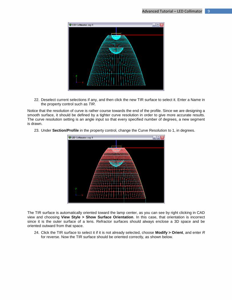
22. Deselect current selections if any, and then click the new TIR surface to select it. Enter a Name in the property control such as TIR.
Notice that the resolution of curve is rather course towards the end of the profile. Since we are designing a smooth surface, it should be defined by a tighter curve resolution in order to give more accurate results. The curve resolution setting is an angle input so that every specified number of degrees, a new segment is drawn.
23. Under Section/Profile in the property control, change the Curve Resolution to 1, in degrees.
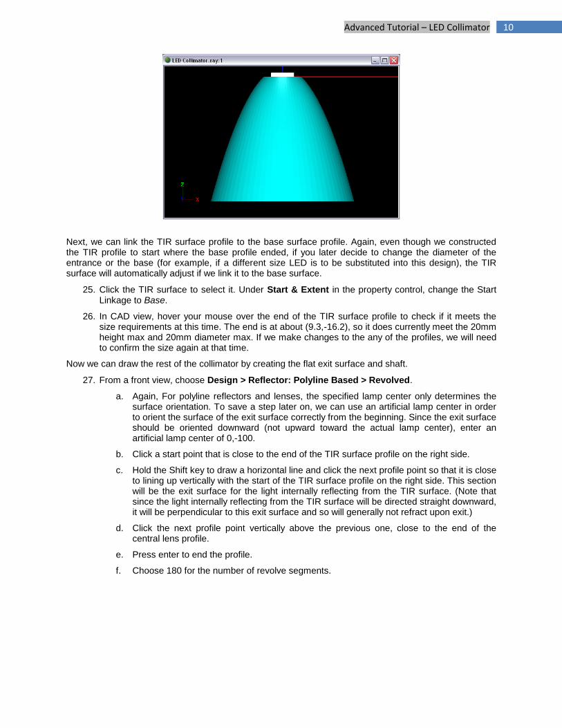
The TIR surface is automatically oriented toward the lamp center, as you can see by right clicking in CAD
view and choosing View Style > Show Surface Orientation. In this case, that orientation is incorrect since it is the outer surface of a lens. Refractor surfaces should always enclose a 3D space and be oriented outward from that space.
24. Click the TIR surface to select it if it is not already selected, choose Modify > Orient, and enter R for reverse. Now the TIR surface should be oriented correctly, as shown below.
10 Advanced Tutorial – LED Collimator
Next, we can link the TIR surface profile to the base surface profile. Again, even though we constructed the TIR profile to start where the base profile ended, if you later decide to change the diameter of the entrance or the base (for example, if a different size LED is to be substituted into this design), the TIR surface will automatically adjust if we link it to the base surface.
25. Click the TIR surface to select it. Under Start & Extent in the property control, change the Start Linkage to Base.
26. In CAD view, hover your mouse over the end of the TIR surface profile to check if it meets the size requirements at this time. The end is at about (9.3,-16.2), so it does currently meet the 20mm height max and 20mm diameter max. If we make changes to the any of the profiles, we will need to confirm the size again at that time.
Now we can draw the rest of the collimator by creating the flat exit surface and shaft.
27. From a front view, choose Design > Reflector: Polyline Based > Revolved.
a. Again, For polyline reflectors and lenses, the specified lamp center only determines the surface orientation. To save a step later on, we can use an artificial lamp center in order to orient the surface of the exit surface correctly from the beginning. Since the exit surface should be oriented downward (not upward toward the actual lamp center), enter an artificial lamp center of 0,-100.
b. Click a start point that is close to the end of the TIR surface profile on the right side.
c. Hold the Shift key to draw a horizontal line and click the next profile point so that it is close to lining up vertically with the start of the TIR surface profile on the right side. This section will be the exit surface for the light internally reflecting from the TIR surface. (Note that since the light internally reflecting from the TIR surface will be directed straight downward, it will be perpendicular to this exit surface and so will generally not refract upon exit.)
d. Click the next profile point vertically above the previous one, close to the end of the central lens profile.
e. Press enter to end the profile.
f. Choose 180 for the number of revolve segments.
11 Advanced Tutorial – LED Collimator
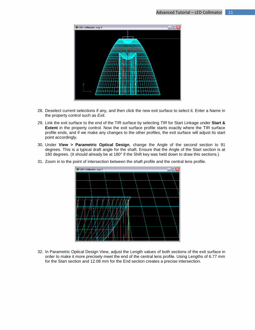
28. Deselect current selections if any, and then click the new exit surface to select it. Enter a Name in the property control such as Exit.
29. Link the exit surface to the end of the TIR surface by selecting TIR for Start Linkage under Start &
Extent in the property control. Now the exit surface profile starts exactly where the TIR surface profile ends, and if we make any changes to the other profiles, the exit surface will adjust its start point accordingly.
30. Under View > Parametric Optical Design, change the Angle of the second section to 91 degrees. This is a typical draft angle for the shaft. Ensure that the Angle of the Start section is at 180 degrees. (It should already be at 180° if the Shift key was held down to draw this sections.)
31. Zoom in to the point of intersection between the shaft profile and the central lens profile.
32. In Parametric Optical Design View, adjust the Length values of both sections of the exit surface in order to make it more precisely meet the end of the central lens profile. Using Lengths of 6.77 mm for the Start section and 12.08 mm for the End section creates a precise intersection.
12 Advanced Tutorial – LED Collimator
Check the Central Lens Location
The central lens should be placed so that most of the light from the LED will either be controlled by the TIR surface or by the central lens, without allowing light to miss both surfaces and without the center lens intercepting the light that reflects from the TIR surface.
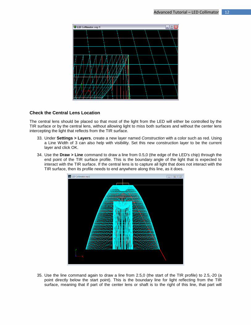
33. Under Settings > Layers, create a new layer named Construction with a color such as red. Using a Line Width of 3 can also help with visibility. Set this new construction layer to be the current layer and click OK.
34. Use the Draw > Line command to draw a line from 0.5,0 (the edge of the LED's chip) through the end point of the TIR surface profile. This is the boundary angle of the light that is expected to interact with the TIR surface. If the central lens is to capture all light that does not interact with the TIR surface, then its profile needs to end anywhere along this line, as it does.
35. Use the line command again to draw a line from 2.5,0 (the start of the TIR profile) to 2.5,-20 (a point directly below the start point). This is the boundary line for light reflecting from the TIR surface, meaning that if part of the center lens or shaft is to the right of this line, that part will
13 Advanced Tutorial – LED Collimator
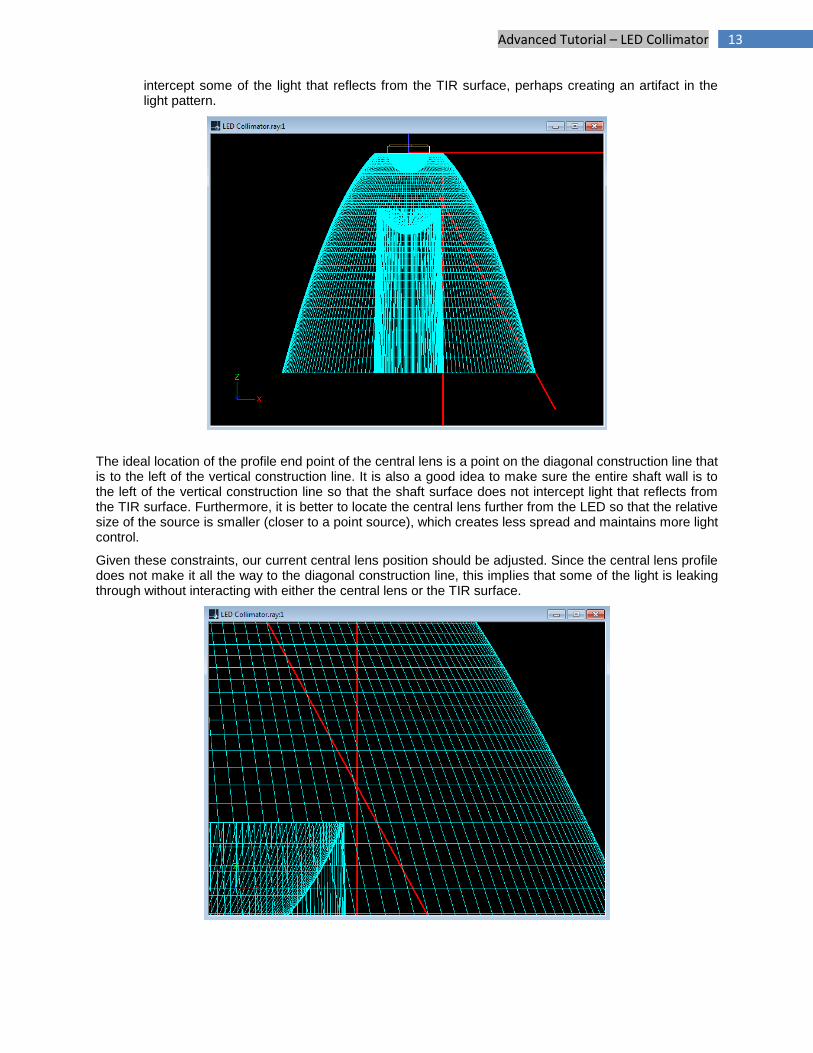
intercept some of the light that reflects from the TIR surface, perhaps creating an artifact in the light pattern.
The ideal location of the profile end point of the central lens is a point on the diagonal construction line that is to the left of the vertical construction line. It is also a good idea to make sure the entire shaft wall is to the left of the vertical construction line so that the shaft surface does not intercept light that reflects from the TIR surface. Furthermore, it is better to locate the central lens further from the LED so that the relative size of the source is smaller (closer to a point source), which creates less spread and maintains more light control.
Given these constraints, our current central lens position should be adjusted. Since the central lens profile does not make it all the way to the diagonal construction line, this implies that some of the light is leaking through without interacting with either the central lens or the TIR surface.
14 Advanced Tutorial – LED Collimator
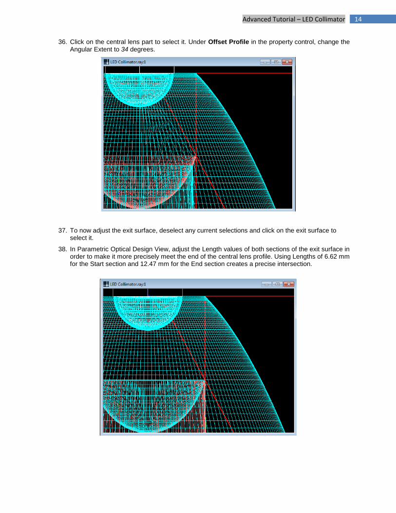
36. Click on the central lens part to select it. Under Offset Profile in the property control, change the Angular Extent to 34 degrees.
37. To now adjust the exit surface, deselect any current selections and click on the exit surface to select it.
38. In Parametric Optical Design View, adjust the Length values of both sections of the exit surface in order to make it more precisely meet the end of the central lens profile. Using Lengths of 6.62 mm for the Start section and 12.47 mm for the End section creates a precise intersection.
15 Advanced Tutorial – LED Collimator
Setup the Materials and Output
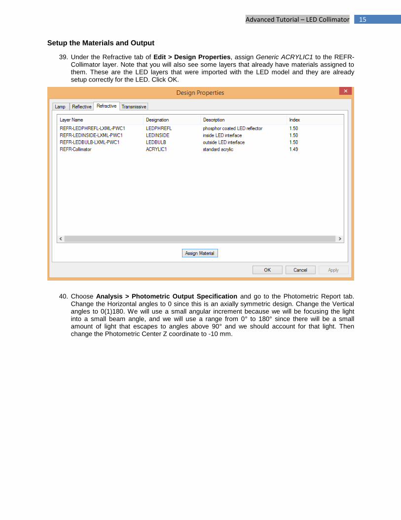
39. Under the Refractive tab of Edit > Design Properties, assign Generic ACRYLIC1 to the REFR-Collimator layer. Note that you will also see some layers that already have materials assigned to them. These are the LED layers that were imported with the LED model and they are already setup correctly for the LED. Click OK.
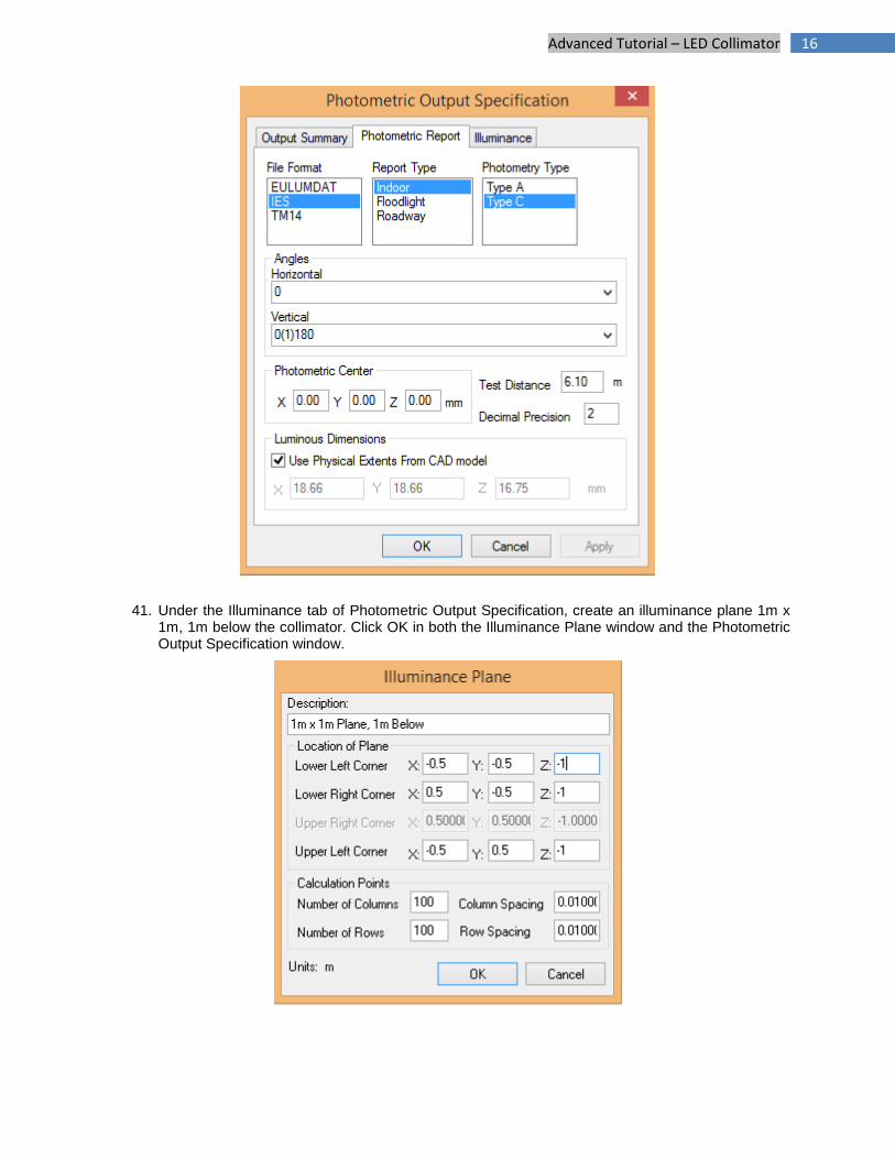
40. Choose Analysis > Photometric Output Specification and go to the Photometric Report tab. Change the Horizontal angles to 0 since this is an axially symmetric design. Change the Vertical angles to 0(1)180. We will use a small angular increment because we will be focusing the light into a small beam angle, and we will use a range from 0° to 180° since there will be a small amount of light that escapes to angles above 90° and we should account for that light. Then change the Photometric Center Z coordinate to -10 mm.
16 Advanced Tutorial – LED Collimator
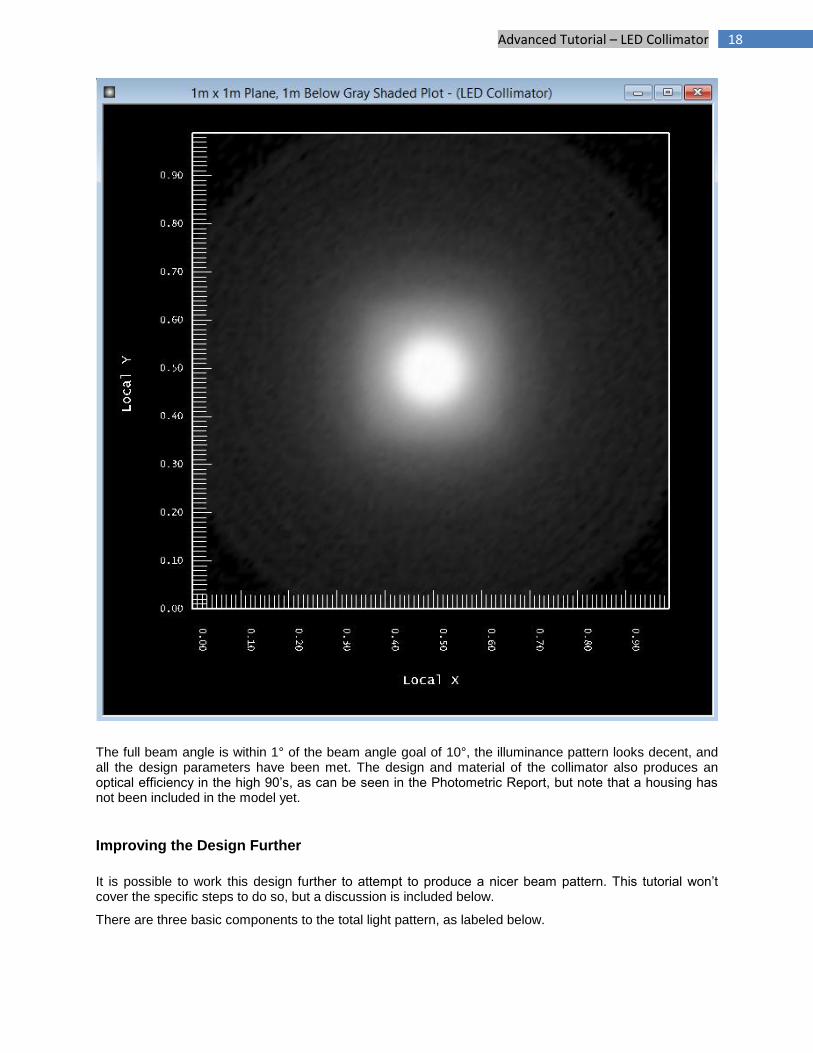
41. Under the Illuminance tab of Photometric Output Specification, create an illuminance plane 1m x 1m, 1m below the collimator. Click OK in both the Illuminance Plane window and the Photometric Output Specification window.
17 Advanced Tutorial – LED Collimator
Design Results
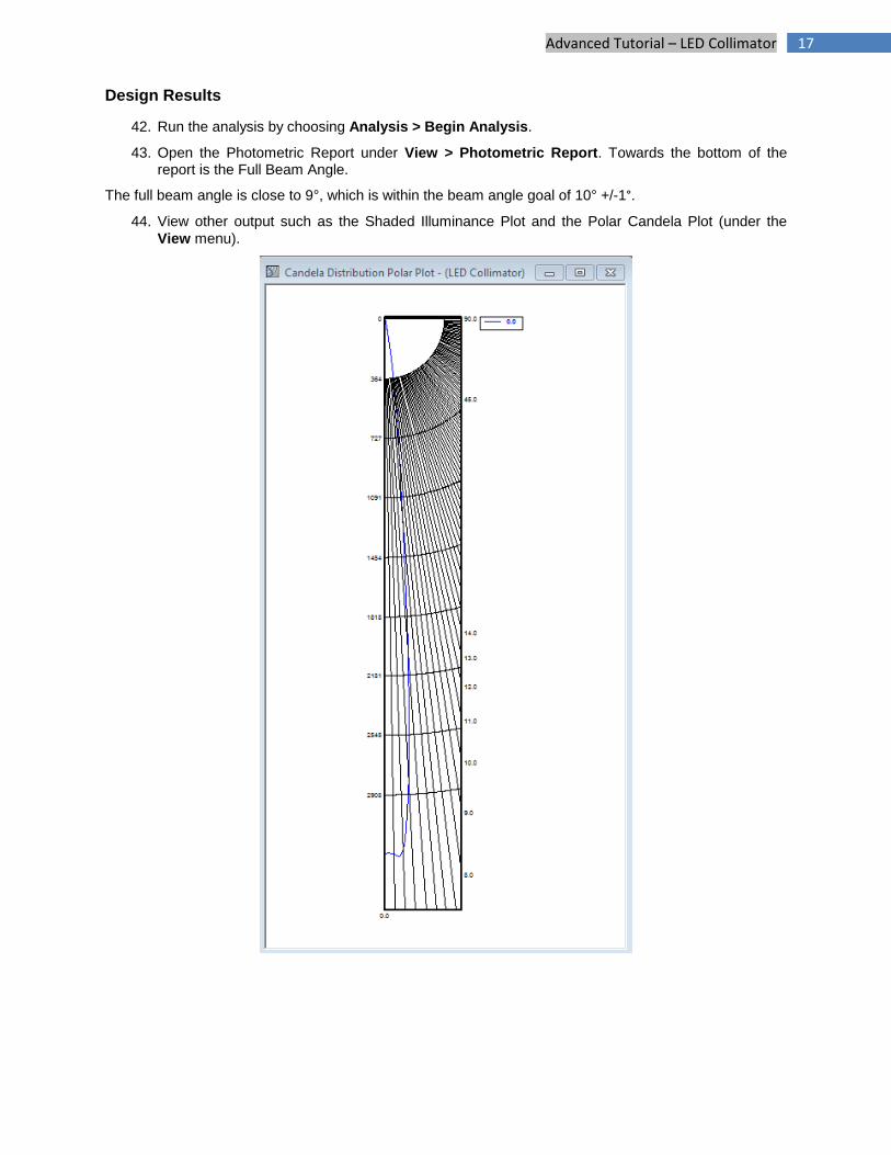
42. Run the analysis by choosing Analysis > Begin Analysis.
43. Open the Photometric Report under View > Photometric Report. Towards the bottom of the report is the Full Beam Angle.
The full beam angle is close to 9°, which is within the beam angle goal of 10° +/-1°.
44. View other output such as the Shaded Illuminance Plot and the Polar Candela Plot (under the
View menu).
18 Advanced Tutorial – LED Collimator
The full beam angle is within 1° of the beam angle goal of 10°, the illuminance pattern looks decent, and all the design parameters have been met. The design and material of the collimator also produces an optical efficiency in the high 90’s, as can be seen in the Photometric Report, but note that a housing has not been included in the model yet.
Improving the Design Further
It is possible to work this design further to attempt to produce a nicer beam pattern. This tutorial won’t cover the specific steps to do so, but a discussion is included below.
There are three basic components to the total light pattern, as labeled below.

19 Advanced Tutorial – LED Collimator
The spot labeled ‘A’ is the resulting pattern from the TIR part of the collimator. The spot labeled ‘B’ is the resulting pattern from the central refractive lens part of the collimator. The spill light labeled ‘C’ is an unintentional side effect of interactions between lens surfaces.
The B spot is slightly larger than the A spot because its optical surfaces are closer to the LED, so it essentially has a relatively larger source that is further from the ideal point source. There is more relative spread onto the optical surfaces of the B spot than onto those of the A spot, because its optical surfaces are closer to the LED.
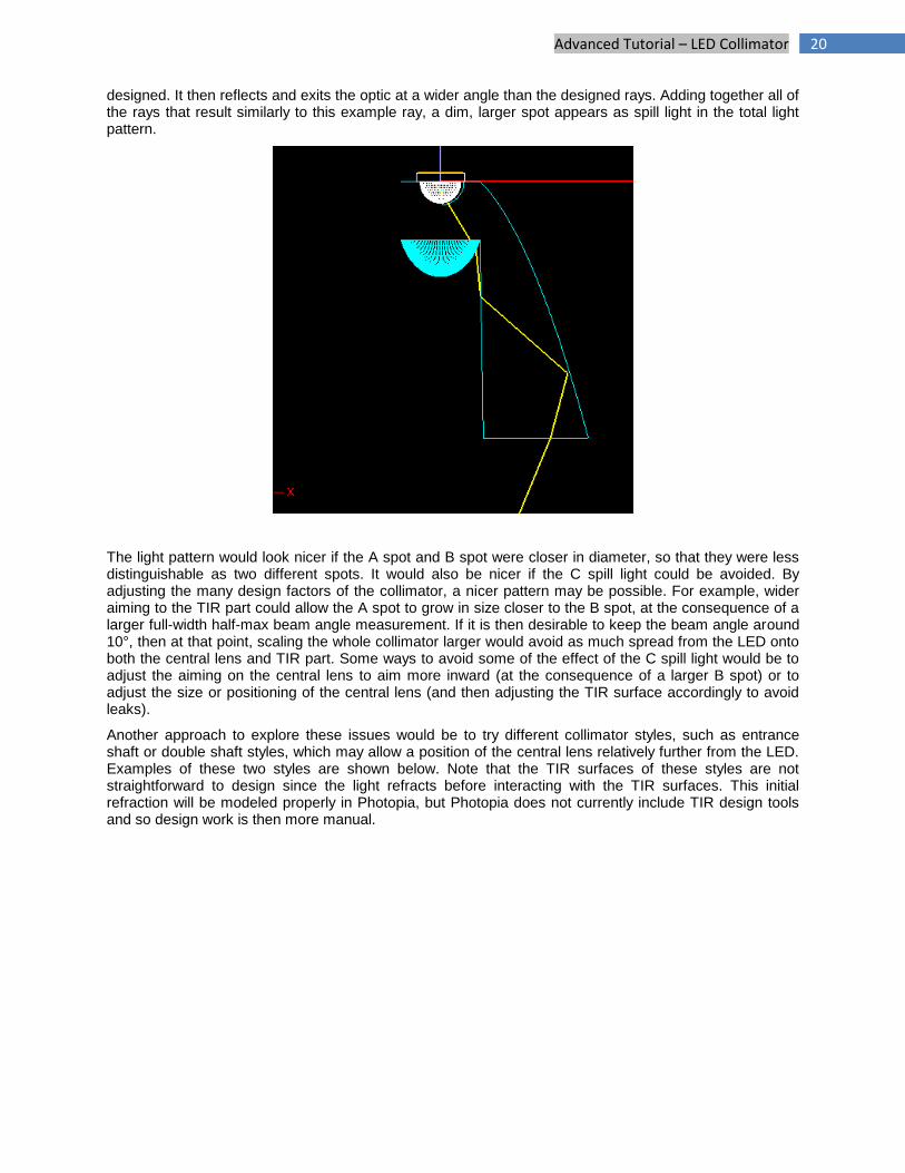
The C spill light side effect is also related to spread due to source size. An example ray is shown below. This ray originates from the LED chip, off-center and therefore not from the focal point for which the central lens is designed. When the ray refracts out from the central lens, it leaves at a slightly higher angle than it is designed for because its origin is slightly off-focus. Its path is at too high of an angle to escape without entering the optic again, this time through the shaft wall. Upon entrance, it refracts high enough to then interact with the TIR surface, at a significantly different angle than that for which the TIR surface is
A
B
C
20 Advanced Tutorial – LED Collimator
designed. It then reflects and exits the optic at a wider angle than the designed rays. Adding together all of the rays that result similarly to this example ray, a dim, larger spot appears as spill light in the total light pattern.
The light pattern would look nicer if the A spot and B spot were closer in diameter, so that they were less distinguishable as two different spots. It would also be nicer if the C spill light could be avoided. By adjusting the many design factors of the collimator, a nicer pattern may be possible. For example, wider aiming to the TIR part could allow the A spot to grow in size closer to the B spot, at the consequence of a larger full-width half-max beam angle measurement. If it is then desirable to keep the beam angle around 10°, then at that point, scaling the whole collimator larger would avoid as much spread from the LED onto both the central lens and TIR part. Some ways to avoid some of the effect of the C spill light would be to adjust the aiming on the central lens to aim more inward (at the consequence of a larger B spot) or to adjust the size or positioning of the central lens (and then adjusting the TIR surface accordingly to avoid leaks).
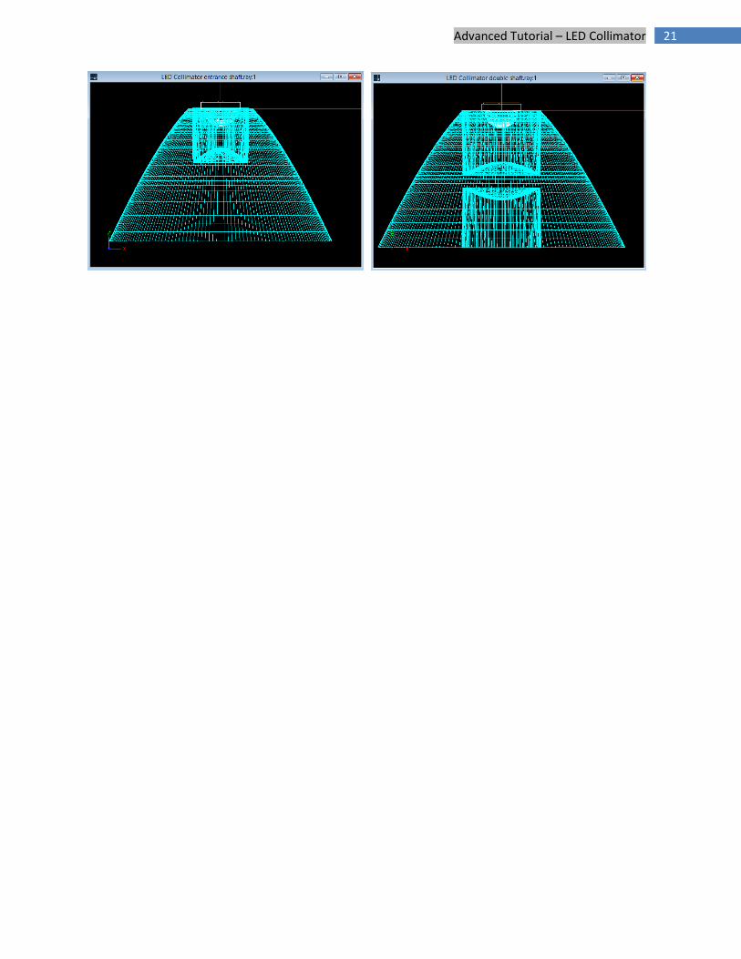
Another approach to explore these issues would be to try different collimator styles, such as entrance shaft or double shaft styles, which may allow a position of the central lens relatively further from the LED. Examples of these two styles are shown below. Note that the TIR surfaces of these styles are not straightforward to design since the light refracts before interacting with the TIR surfaces. This initial refraction will be modeled properly in Photopia, but Photopia does not currently include TIR design tools and so design work is then more manual.
21 Advanced Tutorial – LED Collimator