Embed Size (px)
Citation preview
TM
September 2013
TM 2
• Introduction
• Networking Protocols
• Networking future trends
• Roadmaps
• Competitive advantage
• Conclusions
3 TM
TM
5 TM
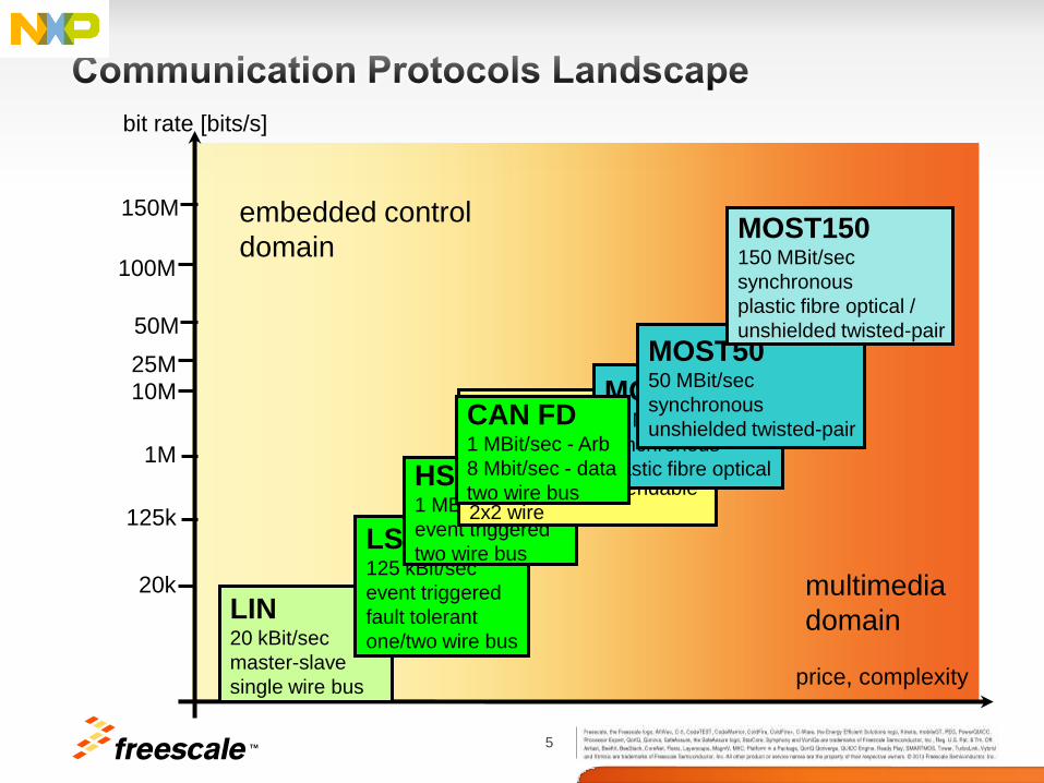
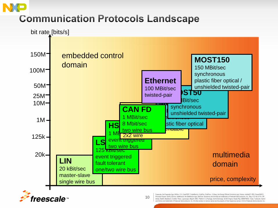
price, complexity
bit rate [bits/s]
LIN 20 kBit/sec
master-slave
single wire bus
20k
125k
1M
10M
25M
LS CAN 125 kBit/sec
event triggered
fault tolerant
one/two wire bus
multimedia
domain
50M
100M
150M
HS CAN 1 MBit/sec
event triggered
two wire bus
embedded control
domain
FlexRay 10 MBit/sec
time triggered
fault tolerant, dependable
2x2 wire
MOST25 25 MBit/sec
synchronous
plastic fibre optical
MOST50 50 MBit/sec
synchronous
unshielded twisted-pair
MOST150 150 MBit/sec
synchronous
plastic fibre optical /
unshielded twisted-pair
CAN FD 1 MBit/sec - Arb
8 Mbit/sec - data
two wire bus
6 TM
• Motivation
− Bandwidth need is on the increase
E.g. Future growth, functional safety
− Increased demand for >8 byte message
E.g. Software authentication
− Improve fault confinement
Notification of system bus degradation
− Provide CAN upgrade path without major network re-design
• New Features added
− Increase Bit Rate
Arbitration phase: up to 1Mbps; Data phase: up to 8Mbps
− Increase Payload
Up to 64bytes
− Error status indicator
• Remote frames not supported
7 TM
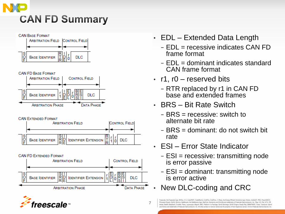
• EDL – Extended Data Length
− EDL = recessive indicates CAN FD frame format
− EDL = dominant indicates standard CAN frame format
• r1, r0 – reserved bits
− RTR replaced by r1 in CAN FD base and extended frames
• BRS – Bit Rate Switch
− BRS = recessive: switch to alternate bit rate
− BRS = dominant: do not switch bit rate
• ESI – Error State Indicator
− ESI = recessive: transmitting node is error passive
− ESI = dominant: transmitting node is error active
• New DLC-coding and CRC
8 TM
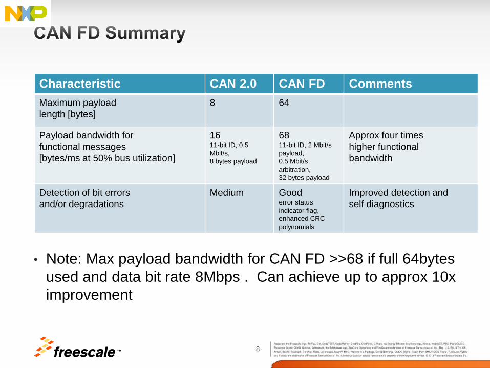
• Note: Max payload bandwidth for CAN FD >>68 if full 64bytes
used and data bit rate 8Mbps . Can achieve up to approx 10x
improvement
Characteristic CAN 2.0 CAN FD Comments
Maximum payload
length [bytes]
8 64
Payload bandwidth for
functional messages
[bytes/ms at 50% bus utilization]
16 11-bit ID, 0.5
Mbit/s,
8 bytes payload
68 11-bit ID, 2 Mbit/s
payload,
0.5 Mbit/s
arbitration,
32 bytes payload
Approx four times
higher functional
bandwidth
Detection of bit errors
and/or degradations
Medium Good error status
indicator flag,
enhanced CRC
polynomials
Improved detection and
self diagnostics
9 TM
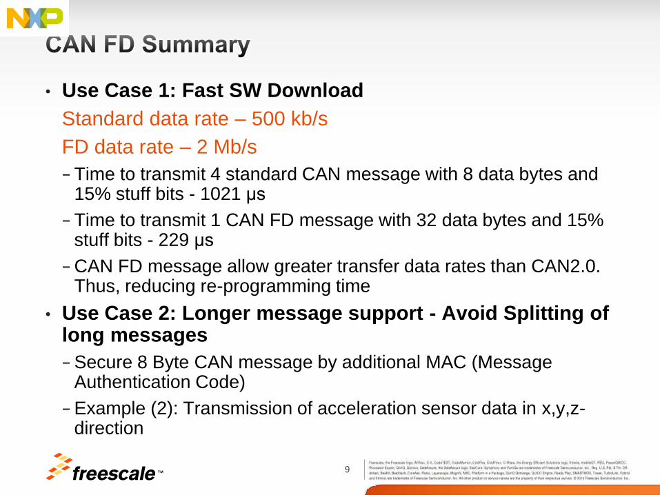
• Use Case 1: Fast SW Download
Standard data rate – 500 kb/s
FD data rate – 2 Mb/s
− Time to transmit 4 standard CAN message with 8 data bytes and 15% stuff bits - 1021 μs
− Time to transmit 1 CAN FD message with 32 data bytes and 15% stuff bits - 229 μs
− CAN FD message allow greater transfer data rates than CAN2.0. Thus, reducing re-programming time
• Use Case 2: Longer message support - Avoid Splitting of long messages
− Secure 8 Byte CAN message by additional MAC (Message Authentication Code)
− Example (2): Transmission of acceleration sensor data in x,y,z-direction
10 TM
price, complexity
bit rate [bits/s]
LIN 20 kBit/sec
master-slave
single wire bus
20k
125k
1M
10M
25M
LS CAN 125 kBit/sec
event triggered
fault tolerant
one/two wire bus
multimedia
domain
50M
100M
150M
HS CAN 1 MBit/sec
event triggered
two wire bus
embedded control
domain
FlexRay 10 MBit/sec
time triggered
fault tolerant, dependable
2x2 wire
MOST25 25 MBit/sec
synchronous
plastic fiber optical
MOST50 50 MBit/sec
synchronous
unshielded twisted-pair CAN FD 1 MBit/sec
8 Mbit/sec
two wire bus
MOST150 150 MBit/sec
synchronous
plastic fiber optical /
unshielded twisted-pair Ethernet 100 MBit/sec
twisted-pair
11 TM
• Widely used network standard (IEEE 802.3) for LANs
• Several speed grades:
− 10 baseT, 100 baseT, 1000 baseT….
• Auto qualified Physical layer based on Unshielded twisted pair (TP) wire
• Multiple Phy to MAC Interfaces
− MII, MII_Lite, RMII, GMII, RGMII, ....
• Duplex and Half duplex communication
• Ethernet already established in vehicle
− Diagnostics, Ethernet camera
− Ethernet AVB being introduced
• Broad offering of software stacks, tools, expertise makes use of Ethernet cost attractive
12 TM
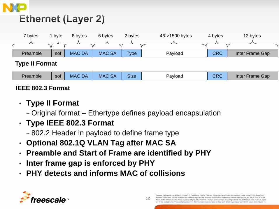
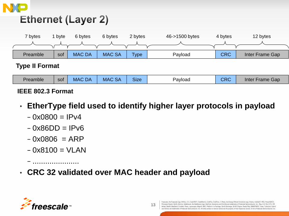
• Type II Format
− Original format – Ethertype defines payload encapsulation
• Type IEEE 802.3 Format
− 802.2 Header in payload to define frame type
• Optional 802.1Q VLAN Tag after MAC SA
• Preamble and Start of Frame are identified by PHY
• Inter frame gap is enforced by PHY
• PHY detects and informs MAC of collisions
Preamble sof MAC DA MAC SA Type Payload CRC Inter Frame Gap
7 bytes 1 byte 6 bytes 6 bytes 2 bytes 46->1500 bytes 4 bytes 12 bytes
Preamble sof MAC DA MAC SA Size Payload CRC Inter Frame Gap
Type II Format
IEEE 802.3 Format
13 TM
• EtherType field used to identify higher layer protocols in payload
− 0x0800 = IPv4
− 0x86DD = IPv6
− 0x0806 = ARP
− 0x8100 = VLAN
− ......................
• CRC 32 validated over MAC header and payload
Preamble sof MAC DA MAC SA Type Payload CRC Inter Frame Gap
7 bytes 1 byte 6 bytes 6 bytes 2 bytes 46->1500 bytes 4 bytes 12 bytes
Preamble sof MAC DA MAC SA Size Payload CRC Inter Frame Gap
Type II Format
IEEE 802.3 Format
14 TM
• IEEE 802.1 Audio/Video Bridging (AVB) standards enable time-synchronized low latency streaming services through 802 networks.
− Ensures interoperability between devices using AVB
• AVB technology allows network to reserves the necessary bandwidth and resources
− Ensure that the signal reaches its destination in a precisely pre-determined amount of time synchronized across all outputs.
− Aim is to minimise the amount of buffering to keep costs down
• Four IEEE 802.1 AVB standards form the foundation of AVB technology
− IEEE 802.1AS (PTP): “Timing and Synchronization for Time-Sensitive Applications in Bridged Local Area Networks.”
− IEEE 802.1Qat (SRP): “Virtual Bridged Local Area Networks - Amendment 9: Stream Reservation Protocol (SRP) .”
− IEEE 802.1Qav (Qav): “Virtual Bridged Local Area Networks - Amendment 11: Forwarding and Queuing for Time- Sensitive Streams.”
− IEEE 802.1BA: “Audio/Video Bridging(AVB) Systems”
15 TM
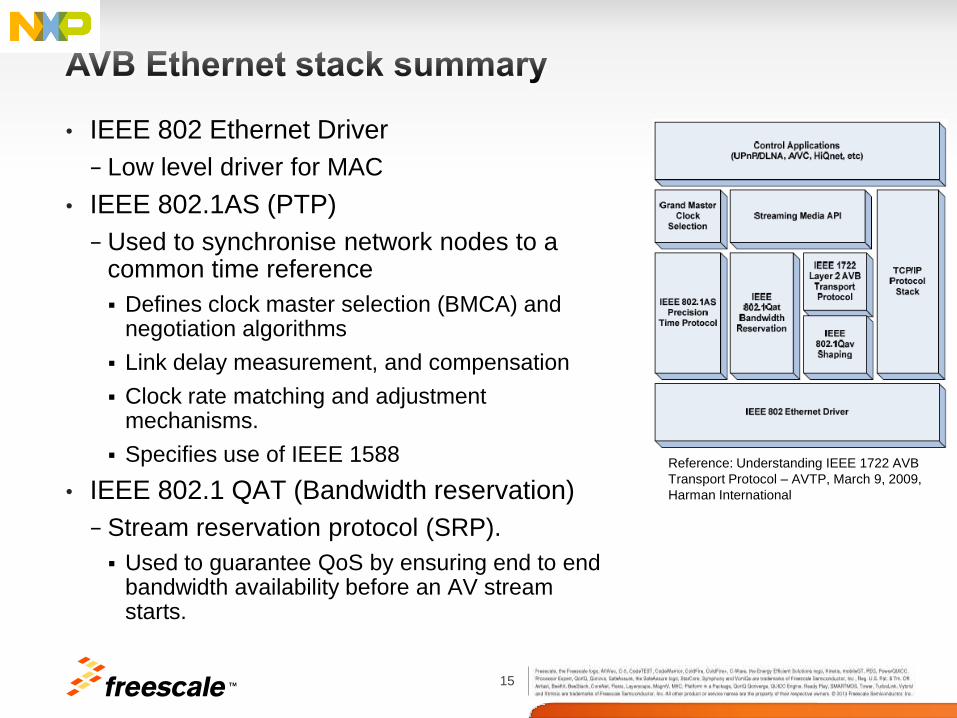
• IEEE 802 Ethernet Driver
− Low level driver for MAC
• IEEE 802.1AS (PTP)
− Used to synchronise network nodes to a common time reference
Defines clock master selection (BMCA) and negotiation algorithms
Link delay measurement, and compensation
Clock rate matching and adjustment mechanisms.
Specifies use of IEEE 1588
• IEEE 802.1 QAT (Bandwidth reservation)
− Stream reservation protocol (SRP).
Used to guarantee QoS by ensuring end to end bandwidth availability before an AV stream starts.
Reference: Understanding IEEE 1722 AVB
Transport Protocol – AVTP, March 9, 2009,
Harman International
16 TM
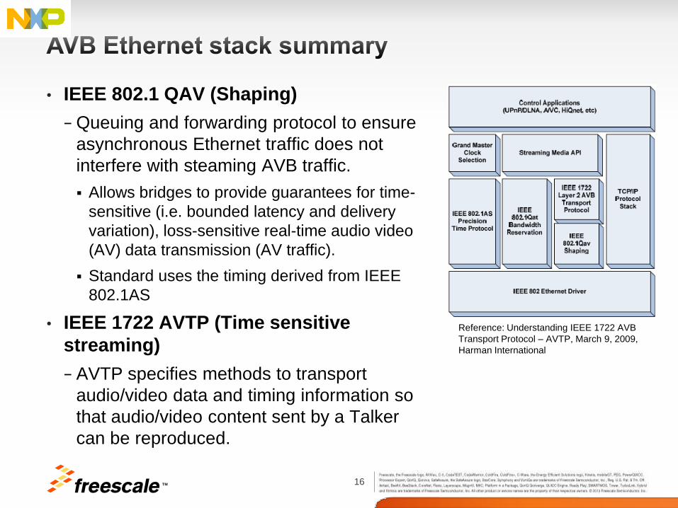
• IEEE 802.1 QAV (Shaping)
− Queuing and forwarding protocol to ensure
asynchronous Ethernet traffic does not
interfere with steaming AVB traffic.
Allows bridges to provide guarantees for time-
sensitive (i.e. bounded latency and delivery
variation), loss-sensitive real-time audio video
(AV) data transmission (AV traffic).
Standard uses the timing derived from IEEE
802.1AS
• IEEE 1722 AVTP (Time sensitive
streaming)
− AVTP specifies methods to transport
audio/video data and timing information so
that audio/video content sent by a Talker
can be reproduced.
Reference: Understanding IEEE 1722 AVB
Transport Protocol – AVTP, March 9, 2009,
Harman International
17 TM
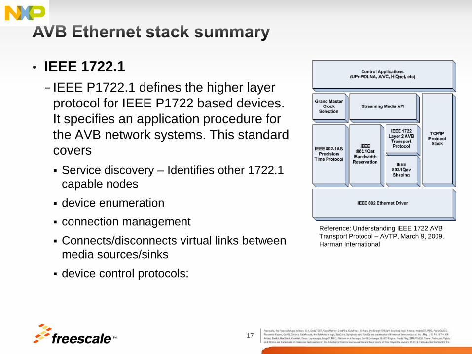
• IEEE 1722.1
− IEEE P1722.1 defines the higher layer
protocol for IEEE P1722 based devices.
It specifies an application procedure for
the AVB network systems. This standard
covers
Service discovery – Identifies other 1722.1
capable nodes
device enumeration
connection management
Connects/disconnects virtual links between
media sources/sinks
device control protocols:
Reference: Understanding IEEE 1722 AVB
Transport Protocol – AVTP, March 9, 2009,
Harman International
TM
19 TM
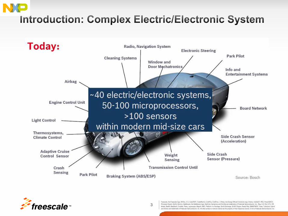
• Cross-domain car communication E.g. increasing safety enabled by data interaction between active safety and advanced driver assistance functions
• Networking of Cars and Environment Car2car communication for efficient organization of traffic flow
• More comfort and safety features in the car
− Camera’s, TFT displays, connectivity, functional safety
− Example for average car
~40 electric/electronic systems
50-100 MCUs
>100 sensors
• Memory and performance on the increase
− Modern car up to 50Mbyte (excludes infotainment)
20 TM
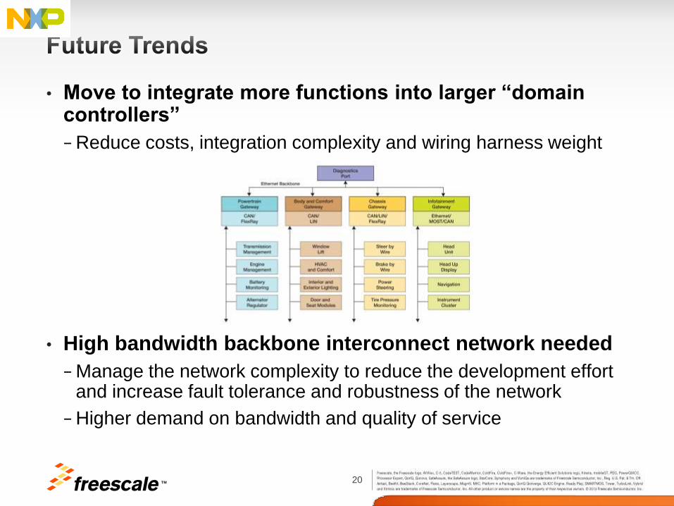
• Move to integrate more functions into larger “domain controllers”
− Reduce costs, integration complexity and wiring harness weight
• High bandwidth backbone interconnect network needed
− Manage the network complexity to reduce the development effort and increase fault tolerance and robustness of the network
− Higher demand on bandwidth and quality of service
21 TM
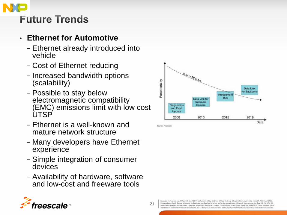
• Ethernet for Automotive
− Ethernet already introduced into vehicle
− Cost of Ethernet reducing
− Increased bandwidth options (scalability)
− Possible to stay below electromagnetic compatibility (EMC) emissions limit with low cost UTSP
− Ethernet is a well-known and mature network structure
− Many developers have Ethernet experience
− Simple integration of consumer devices
− Availability of hardware, software and low-cost and freeware tools
TM
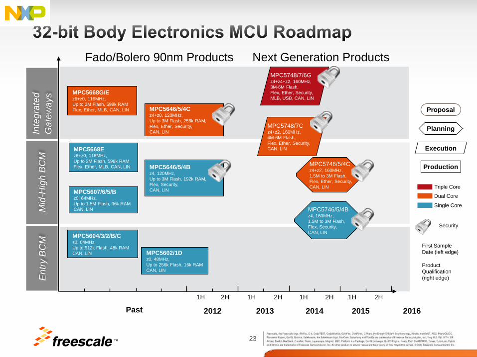
23 TM
Single Core
Dual Core MPC5607/6/5/B z0, 64MHz,
Up to 1.5M Flash, 96k RAM
CAN, LIN
En
try B
CM
Past 2012 2014 2016
MPC5604/3/2/B/C z0, 64MHz,
Up to 512k Flash, 48k RAM
CAN, LIN MPC5602/1D z0, 48MHz,
Up to 256k Flash, 16k RAM
CAN, LIN
Mid
-Hig
h B
CM
In
teg
rate
d
Ga
tew
ays MPC5668G/E
z6+z0, 116MHz,
Up to 2M Flash, 598k RAM
Flex, Ether, MLB, CAN, LIN
2013 2015
MPC5668E z6+z0, 116MHz,
Up to 2M Flash, 598k RAM
Flex, Ether, MLB, CAN, LIN
Triple Core
First Sample
Date (left edge)
Production
Proposal
Planning
Execution
Product
Qualification
(right edge)
1H 1H 1H 1H 2H 2H 2H 2H
MPC5646/5/4C z4+z0, 120MHz,
Up to 3M Flash, 256k RAM,
Flex, Ether, Security,
CAN, LIN
MPC5646/5/4B z4, 120MHz,
Up to 3M Flash, 192k RAM,
Flex, Security,
CAN, LIN
Fado/Bolero 90nm Products Next Generation Products
MPC5748/7/6G z4+z4+z2, 160MHz,
3M-6M Flash,
Flex, Ether, Security,
MLB, USB, CAN, LIN
MPC5746/5/4B z4, 160MHz,
1.5M to 3M Flash,
Flex, Security,
CAN, LIN
MPC5748/7C z4+z2, 160MHz,
4M-6M Flash,
Flex, Ether, Security,
CAN, LIN
MPC5746/5/4C z4+z2, 160MHz,
1.5M to 3M Flash,
Flex, Ether, Security,
CAN, LIN
Security
24 TM
256k
SRAM
(with ECC)
256k
SRAM
(with ECC)
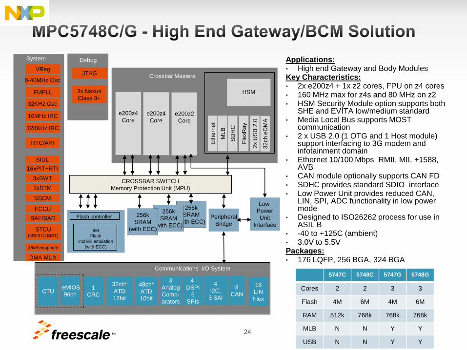
Applications: • High end Gateway and Body Modules Key Characteristics: • 2x e200z4 + 1x z2 cores, FPU on z4 cores • 160 MHz max for z4s and 80 MHz on z2 • HSM Security Module option supports both
SHE and EVITA low/medium standard • Media Local Bus supports MOST
communication • 2 x USB 2.0 (1 OTG and 1 Host module)
support interfacing to 3G modem and infotainment domain
• Ethernet 10/100 Mbps RMII, MII, +1588, AVB
• CAN module optionally supports CAN FD • SDHC provides standard SDIO interface • Low Power Unit provides reduced CAN,
LIN, SPI, ADC functionality in low power mode
• Designed to ISO26262 process for use in ASIL B
• -40 to +125C (ambient) • 3.0V to 5.5V Packages: • 176 LQFP, 256 BGA, 324 BGA
Communications I/O System
48ch*
ATD
10bit
eMIOS
96ch
4
I2C,
3 SAI
4
DSPI
6
SPIs
8
CAN
18
LIN
Flex
32ch*
ATD
12bit
CTU
3
Analog
Comp-
arators
CROSSBAR SWITCH
Memory Protection Unit (MPU)
Crossbar Masters
3x Nexus
Class 3+
JTAG
Debug System
Peripheral
Bridge
HSM
256k
SRAM
(with ECC)
Flash controller
SIUL
16xPIT+RTI
3xSWT
3xSTM
SSCM
STCU (MBIST/LBIST)
FCCU
BAF/BAR
16xSemaphore
DMA MUX
6M
Flash
incl EE emulation
(with ECC)
VReg
RTC/API
8-40MHz Osc
FMPLL
32KHz Osc
16MHz IRC
128KHz IRC
ML
B
SD
HC
Fle
xR
ay
2x U
SB
2.0
Eth
ern
et
e200z2
Core
e200z4
Core
e200z4
Core
1
CRC
5747C 5748C 5747G 5748G
Cores 2 2 3 3
Flash 4M 6M 4M 6M
RAM 512k 768k 768k 768k
MLB N N Y Y
USB N N Y Y
Low
Power
Unit
Interface
32
ch
eD
MA
25 TM
With LIN-PHY
With CAN-PHY
Production Proposal Planning Execution
First Sample Date (left edge) Product Qualification (right edge)
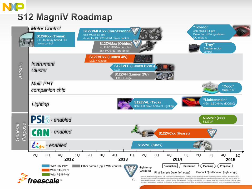
Motor Control
S12VRxx (Tomar) 2 LS for relay based DC
motor control
High temp
(Grade 0)
“Troy” Stepper motor
control
“Toledo” 4ch-MOSFET pre-
Driver for H-Bridge-driven
DC-motors
Instrument
Cluster
S12ZVHxx (Lumen 4W) LCD + Gauge
“Coco” Multi-PHY
Lighting
CAN - enabled
LIN - enabled
Genera
l
Pu
rpo
se
2012 2013 2014 2Q 3Q 4Q 1Q 2Q 3Q 4Q 1Q 2Q 3Q 4Q 1Q 2Q 3Q 4Q
2015 1Q
Other comms (eg. PWM-control)
“Lichtenstein” 4-5ch LED-drive (DC/DC)
S12ZVML/Cxx (Carcassonne) 6ch-MOSFET pre-
driver for BLDC/PMSM motor control
S12ZVMxx (Obidos) No PHY (PWM-control) +
6ch-MOSFET pre-driver
AS
SP
s
S12ZVFP (Lumen HVAC) LCD
S12ZVH (Lumen 2W) LCD + Gauge
Multi-PHY
companion chip
S12ZVAL (Teck) 3ch LED-drive Ambient Lighting
PSI 5 - enabled
S12ZVCxx (Hearst)
With PSI5-PHY
S12ZVP (xxx) S12ZVP
S12ZVL (Knox)
TM 26
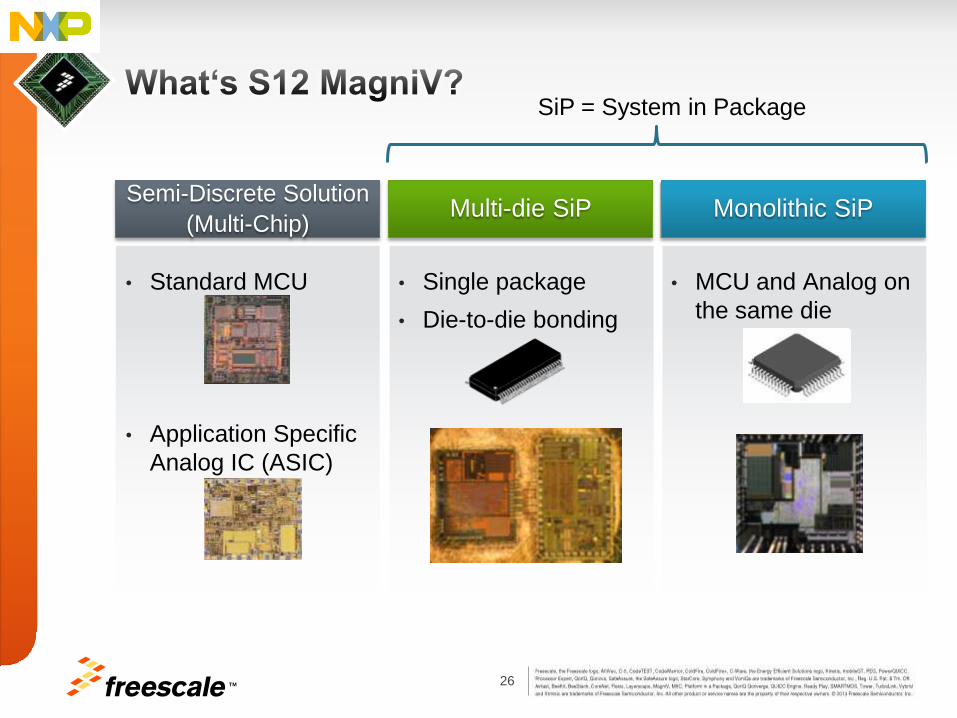
• Standard MCU
• Application Specific
Analog IC (ASIC)
• Single package
• Die-to-die bonding
Semi-Discrete Solution
(Multi-Chip) Multi-die SiP
• MCU and Analog on
the same die
Monolithic SiP
SiP = System in Package
27 TM
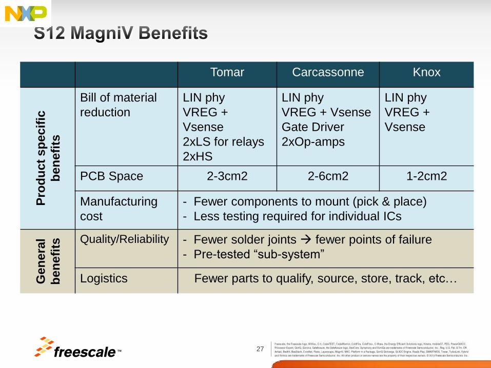
Tomar Carcassonne Knox
Pro
du
ct
sp
ecif
ic
ben
efi
ts
Bill of material
reduction
LIN phy
VREG +
Vsense
2xLS for relays
2xHS
LIN phy
VREG + Vsense
Gate Driver
2xOp-amps
LIN phy
VREG +
Vsense
PCB Space 2-3cm2 2-6cm2 1-2cm2
Manufacturing
cost
- Fewer components to mount (pick & place)
- Less testing required for individual ICs
Gen
era
l
ben
efi
ts Quality/Reliability - Fewer solder joints fewer points of failure
- Pre-tested “sub-system”
Logistics Fewer parts to qualify, source, store, track, etc…
28 TM
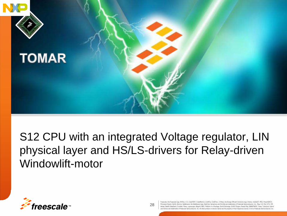
S12 CPU with an integrated Voltage regulator, LIN
physical layer and HS/LS-drivers for Relay-driven
Windowlift-motor
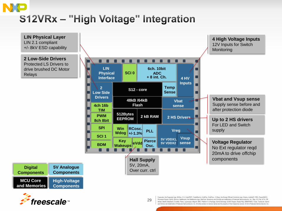
29 TM
S12 - core
Win Wdog
4ch 16b
TIM
Vreg
5V VDDX1,
5V VDDX2
6ch. 10bit
ADC + 8 int. Ch.
PWM
8ch 8bit
SCI 0
Temp
Sense
4 HV
Inputs
2
Low Side
Drivers
LIN
Physical
Interface
Vbat
sense
2 HS Drivers
48kB /64kB
Flash
2 kB RAM 512Bytes
EEPROM
SCI 1
PLL RCosc.
+/-1.3%
Pierce
Osc. BDM Key
Wakeups
Vsup
sense
4 High Voltage Inputs 12V Inputs for Switch
Monitoring
LIN Physical Layer LIN 2.1 compliant
+/- 8kV ESD capability
Vbat and Vsup sense Supply sense before and
after protection diode
Up to 2 HS drivers For LED and Switch
supply SPI
eVdd
Hall Supply 5V, 20mA,
Over curr. ctrl
Voltage Regulator
No Ext regulator reqd
20mA to drive offchip
components
2 Low-Side Drivers Protected LS Drivers to
drive brushed DC Motor
Relays
High-Voltage
Components
Digital
Components
5V Analogue
Components
MCU Core
and Memories
30 TM
16-bit MCU with 12/5V voltage regulator, LIN
physical layer, and MOSFET pre-drivers for DC
and BLDC motors
31 TM
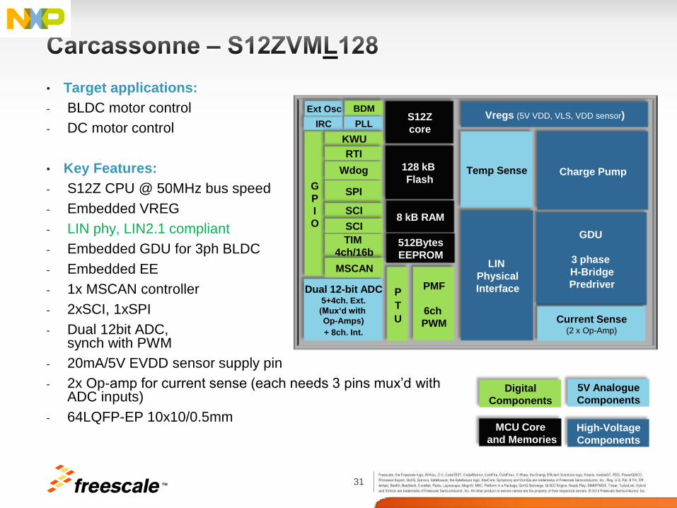
• Target applications:
- BLDC motor control
- DC motor control
• Key Features:
- S12Z CPU @ 50MHz bus speed
- Embedded VREG
- LIN phy, LIN2.1 compliant
- Embedded GDU for 3ph BLDC
- Embedded EE
- 1x MSCAN controller
- 2xSCI, 1xSPI
- Dual 12bit ADC, synch with PWM
- 20mA/5V EVDD sensor supply pin
- 2x Op-amp for current sense (each needs 3 pins mux’d with ADC inputs)
- 64LQFP-EP 10x10/0.5mm
G
P
I
O
S12Z
core
SPI
Wdog
TIM
4ch/16b
Vregs (5V VDD, VLS, VDD sensor)
PMF
6ch
PWM
SCI
Temp Sense
GDU
3 phase
H-Bridge
Predriver
LIN
Physical
Interface
Charge Pump 128 kB
Flash
8 kB RAM
512Bytes
EEPROM
SCI
P
T
U
PLL IRC
Ext Osc BDM
KWU
RTI
Dual 12-bit ADC 5+4ch. Ext.
(Mux‘d with
Op-Amps)
+ 8ch. Int.
MSCAN
Current Sense (2 x Op-Amp)
High-Voltage
Components
Digital
Components
5V Analogue
Components
MCU Core
and Memories
32 TM
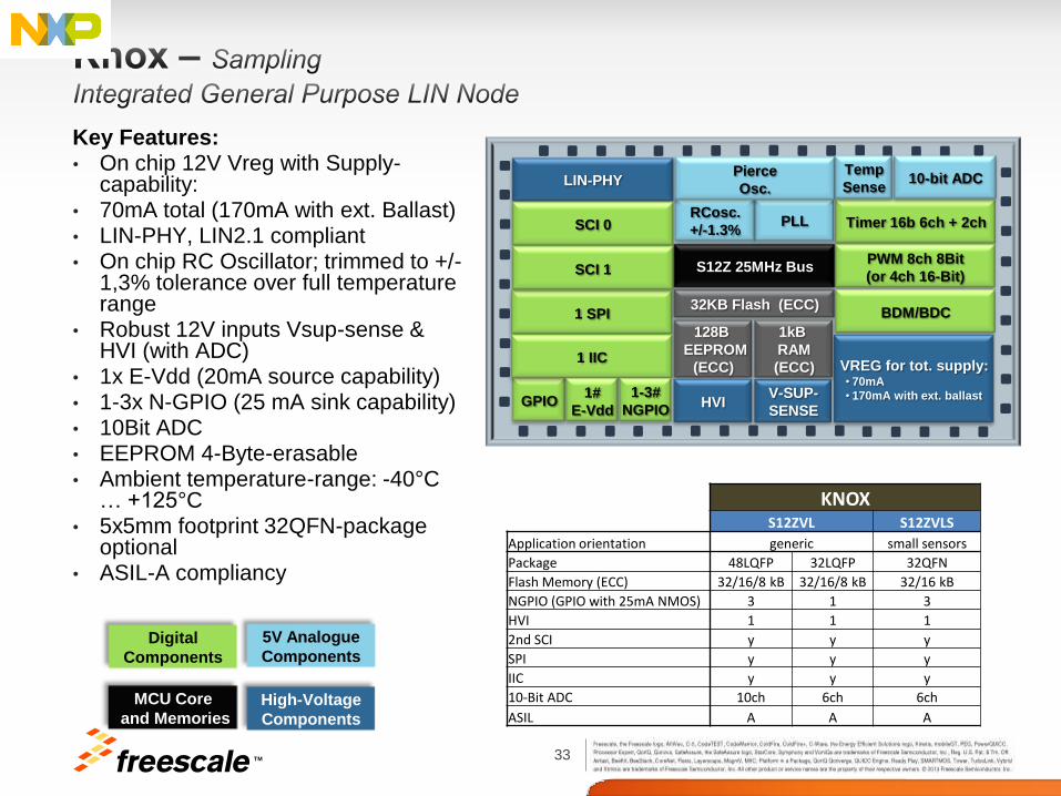
General Purpose S12 MagniV 16-bit MCU with
12/5V voltage regulator, LIN-physical layer
33 TM
Key Features: • On chip 12V Vreg with Supply-
capability: • 70mA total (170mA with ext. Ballast) • LIN-PHY, LIN2.1 compliant • On chip RC Oscillator; trimmed to +/-
1,3% tolerance over full temperature range
• Robust 12V inputs Vsup-sense & HVI (with ADC)
• 1x E-Vdd (20mA source capability) • 1-3x N-GPIO (25 mA sink capability) • 10Bit ADC • EEPROM 4-Byte-erasable • Ambient temperature-range: -40°C
… +125°C • 5x5mm footprint 32QFN-package
optional • ASIL-A compliancy
High-Voltage
Components
Digital
Components
5V Analogue
Components
MCU Core
and Memories
1 SPI
GPIO
Timer 16b 6ch + 2ch
PWM 8ch 8Bit
(or 4ch 16-Bit)
128B
EEPROM
(ECC)
32KB Flash (ECC)
S12Z 25MHz Bus
1 IIC
BDM/BDC
LIN-PHY 10-bit ADC
V-SUP-
SENSE
VREG for tot. supply: • 70mA
• 170mA with ext. ballast
Temp
Sense
1kB
RAM
(ECC)
PLL RCosc.
+/-1.3%
Pierce
Osc.
SCI 0
SCI 1
HVI 1#
E-Vdd
1-3#
NGPIO
KNOX S12ZVL S12ZVLS
Application orientation generic small sensors
Package 48LQFP 32LQFP 32QFN
Flash Memory (ECC) 32/16/8 kB 32/16/8 kB 32/16 kB
NGPIO (GPIO with 25mA NMOS) 3 1 3
HVI 1 1 1
2nd SCI y y y
SPI y y y
IIC y y y
10-Bit ADC 10ch 6ch 6ch
ASIL A A A
TM
35 TM
• Calypso 6M highest end gateway device on the market
• Knowledge of networking and G/W requirements
• Ethernet based products in series production
− First Ethernet Gateway
− Ethernet camera application based on Salsa product
• Comprehensive Ethernet roadmap
− 10/100/1000 Mbit/sec
− Leader in automotive AVB applications
Steaming software
Specific AVB features in Ethernet IP to offload CPU
• Active member of CAN FD working groups
• Early to market with CAN FD
− Supports interleaving CAN 2.0 and CAN FD frames
− Flexible buffer management
36 TM
• MagniV Roadmap
− Monolithic HV technology built upon proven high volume standard
CMOS process
− Integration of high voltage (e.g. CAN Phy, LIN Phy, Vregs)
− Improved reliability
TM 37
• Automotive networking market is evolving with the introduction of
new protocols
• CAN FD, Ethernet AVB
• Freescale provide support for all protocols in Automotive
• LIN, SENT, CAN2.0, CAN FD, FlexRay, Ethernet and Ethernet
AVB, MLB, USB
• Freescale devices developed specifically for gateway market
• Calypso family
• Bolero Family
• Freescale devices support high voltage and power (Magniv)
• LIN Phy, CAN Phy, Vregs
• Lower BOM, higher reliability
TM