Embed Size (px)
Citation preview
Volume 2 • Issue 1 • 1000102Adv Automob EngISSN: 2167-7670 AAE, an open access journal
Open Access Research Article
Advances in Automobile Engineering
Hamzehlouia et al., Adv Automob Eng 2013, 2:1http://dx.doi.org/10.4172/2167-7670.1000102
Keywords: Hybrid electric vehicles; Hydraulic transmission; Regenerative system
IntroductionThe utilization of renewable energies as an alternative for fossil fuels
is considerably growing due to an increasing environmental concern and exhaustion of fossil fuels [1-3]. Transportation electrification is one way to replace or reduce fossil fuels with renewable energy sources. Several propulsion systems including hybrid electric vehicles and plug in hybrid electric vehicles have been introduced to enable usage of renewable energies. A typical hybrid propulsion system has two or more power sources of which at least one can store and reuse energy. The benefits obtained from using such a system are superior fuel economy compared to similar conventional vehicles, emission reductions, and fuel cost savings [4].
Regenerative braking systems use vehicle’s kinetic energy to generate and store electrical energy in battery storage. However, the principal shortcoming of a regenerative braking system is the capability to store the entire re-generated electric power in the battery storage in short time [5]. Therefore, only a small portion of the vehicle’s kinetic energy can be recaptured and stored [6,7]. Hence, alternative techniques are required to increase the amount of recaptured power. One possibility is the usage of a high-pressure hydraulic system. Various configurations of hydraulic energy storage in hydraulic propulsion system have been investigated Hewko et al. [8]. These storage systems can be classified as pure hydrostatic, hydro-mechanical and power assist systems. Other studies [9,10] report 79% fuel economy improvement in a hydraulically assisted hybrid vehicle in urban driving cycle.
Although proven reliable, mechanical transmission systems are subject to frictional losses, which negatively affect overall vehicle efficiency. Several power transmission techniques are developed to address the friction loss issue. These techniques include: a hydraulic hybrid transmission system by the Artemis Intelligent Power company [11], or variable displacement hydrostatic transmission systems [12]. Similar to Continuously Variable Transmission (CVT), the hydraulic transmission provides infinite gear ratio to effectively reduce energy losses and achieve better fuel efficiencies. The application of similar gearless hydraulic power transmission systems has shown promises in wind energy transfer technology [13-15].
Other work present in Tavares, Woon and Johri [16,17] either considers a hybrid powertarin using an electric motor in conjunction with a hydraulic pump/motor circuit [18] or a concept Hefley Engine
connected in parallel with a hydraulic power transfer system that do not have an regeneration capability [16]. A full hybrid hydraulic powertrain complete with an engine as well as an electric generator for recovering brake energies has not been investigated in the literature.
This paper introduces a novel full hybrid-hydraulic propulsion system that enables regenerative braking with various types of storage. Dynamic model of the hydraulic transmission system is created and controlled with a rate limit controller. A range extender internal combustion engine will be used to charge the storage devices as the driving condition changes. Without loss of generality, batteries will be used to accept the charge and discharge while driving in standard driving cycles. A PI controller is designed to manage the discharge current from the battery to run the hydraulic transmission system. The results of the mathematical model will be compared with Sim Hydraulics toolbox of MATLAB. The performance of rate limit propulsion controller and battery management unit will be analyzed.
This paper is organized as follows: section II explains the overall hydraulic power transfer system and its system components. Section III presents the dynamic model of the hydraulic transmission system. A pressure loss calculation model is introduced in section IV. Section V discusses the design of the controllers. Finally, section VI includes the mathematical model verification with computer simulations, and discussion.
Hybrid Hydraulic Transmission System DesignThe hydraulic transmission system for HEVs is designed to provide
electric using two main sources of power as range extender Internal Combustion Engine (ICE) and from Battery storage devices. The hydraulic circuit consists of a fixed displacement pump driven by the prime mover (range extender) and two fixed displacement hydraulic
*Corresponding author: Sohel Anwar, Department of Mechanical Engineering, IUPUIA Purdue University, USA, E-mail: [email protected]
Received January 02, 2013; Accepted January 25, 2013; Published February 02, 2013
Citation: Hamzehlouia S, Izadian A, Anwar S (2013) Modeling and Control of a Hybrid Hydraulic-Electric Propulsion System. Adv Automob Eng 2: 102. doi:10.4172/2167-7670.1000102
Copyright: © 2013 Hamzehlouia S, et al. This is an open-access article distributed under the terms of the Creative Commons Attribution License, which permits unrestricted use, distribution, and reproduction in any medium, provided the original author and source are credited.
AbstractThis paper introduces a gearless hydraulic transmission system that provides an infinite speed ratio similar to
a Continuous Variable Transmission (CVT) with energy storage capabilities. The transmission system is modeled in various operating conditions such as all-electric and gasoline configurations. A Rate Limited (RL) controller is de-signed to control the vehicle traction forces. A PI controller is designed to regulate the charge and discharge power through storage and range extender engine in different driving conditions. The results demonstrate high performance operation of the transmission system in standardized drive cycles. The results show that the control system provides a good speed-command tracking performance.
Modeling and Control of a Hybrid Hydraulic-Electric Propulsion System
1Purdue School of Engineering and Technology, IUPUIA Purdue University, USA2Department of Mechanical Engineering, IUPUIA Purdue University, USA
Sina Hamzehlouia1, Afshin Izadian1 and Sohel Anwar2*
Citation: Hamzehlouia S, Izadian A, Anwar S (2013) Modeling and Control of a Hybrid Hydraulic-Electric Propulsion System. Adv Automob Eng 2: 102. doi:10.4172/2167-7670.1000102
Page 2 of 9
Volume 2 • Issue 1 • 1000102Adv Automob EngISSN: 2167-7670 AAE, an open access journal
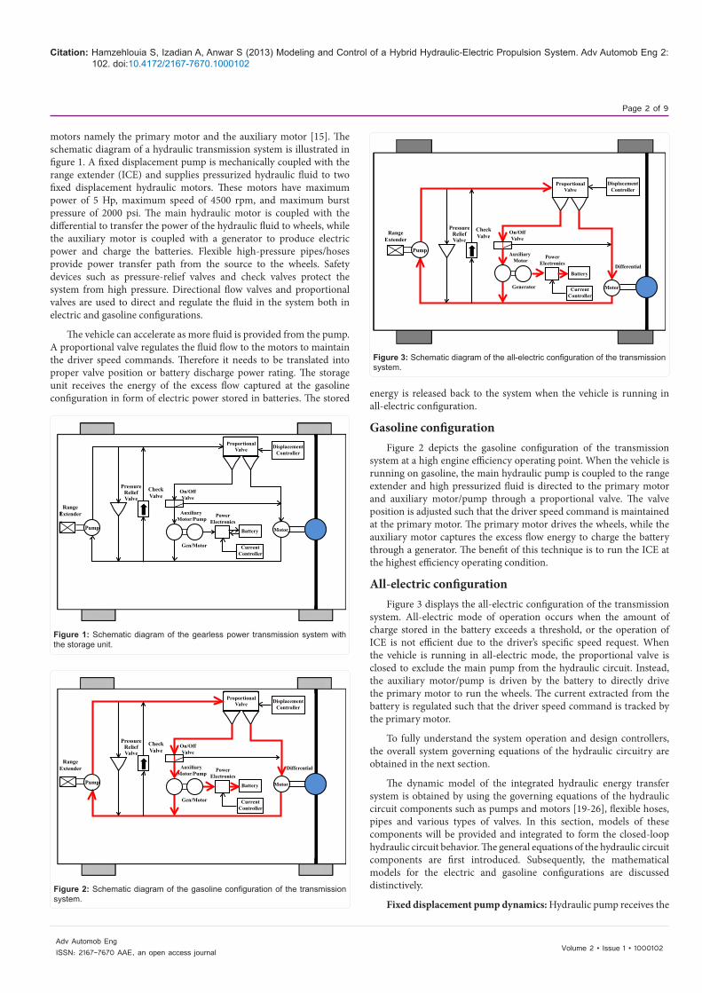
motors namely the primary motor and the auxiliary motor [15]. The schematic diagram of a hydraulic transmission system is illustrated in figure 1. A fixed displacement pump is mechanically coupled with the range extender (ICE) and supplies pressurized hydraulic fluid to two fixed displacement hydraulic motors. These motors have maximum power of 5 Hp, maximum speed of 4500 rpm, and maximum burst pressure of 2000 psi. The main hydraulic motor is coupled with the differential to transfer the power of the hydraulic fluid to wheels, while the auxiliary motor is coupled with a generator to produce electric power and charge the batteries. Flexible high-pressure pipes/hoses provide power transfer path from the source to the wheels. Safety devices such as pressure-relief valves and check valves protect the system from high pressure. Directional flow valves and proportional valves are used to direct and regulate the fluid in the system both in electric and gasoline configurations.
The vehicle can accelerate as more fluid is provided from the pump. A proportional valve regulates the fluid flow to the motors to maintain the driver speed commands. Therefore it needs to be translated into proper valve position or battery discharge power rating. The storage unit receives the energy of the excess flow captured at the gasoline configuration in form of electric power stored in batteries. The stored energy is released back to the system when the vehicle is running in
all-electric configuration.
Gasoline configurationFigure 2 depicts the gasoline configuration of the transmission
system at a high engine efficiency operating point. When the vehicle is running on gasoline, the main hydraulic pump is coupled to the range extender and high pressurized fluid is directed to the primary motor and auxiliary motor/pump through a proportional valve. The valve position is adjusted such that the driver speed command is maintained at the primary motor. The primary motor drives the wheels, while the auxiliary motor captures the excess flow energy to charge the battery through a generator. The benefit of this technique is to run the ICE at the highest efficiency operating condition.
All-electric configurationFigure 3 displays the all-electric configuration of the transmission
system. All-electric mode of operation occurs when the amount of charge stored in the battery exceeds a threshold, or the operation of ICE is not efficient due to the driver’s specific speed request. When the vehicle is running in all-electric mode, the proportional valve is closed to exclude the main pump from the hydraulic circuit. Instead, the auxiliary motor/pump is driven by the battery to directly drive the primary motor to run the wheels. The current extracted from the battery is regulated such that the driver speed command is tracked by the primary motor.
To fully understand the system operation and design controllers, the overall system governing equations of the hydraulic circuitry are obtained in the next section.
The dynamic model of the integrated hydraulic energy transfer system is obtained by using the governing equations of the hydraulic circuit components such as pumps and motors [19-26], flexible hoses, pipes and various types of valves. In this section, models of these components will be provided and integrated to form the closed-loop hydraulic circuit behavior. The general equations of the hydraulic circuit components are first introduced. Subsequently, the mathematical models for the electric and gasoline configurations are discussed distinctively.
Fixed displacement pump dynamics: Hydraulic pump receives the
RangeExtender
Pump
PressureReliefValve
CheckValve
ProportionalValve
On/OffValve
Auxiliary Motor/Pump
Motor
PowerElectronics
Battery
Gen/Motor CurrentController
DisplacementController
Figure 1: Schematic diagram of the gearless power transmission system with the storage unit.
RangeExtender
Pump
PressureReliefValve
CheckValve
ProportionalValve
On/OffValve
Auxiliary Motor/Pump
Motor
DifferentialPowerElectronics
Battery
Gen/Motor CurrentController
DisplacementController
Figure 2: Schematic diagram of the gasoline configuration of the transmission system.
RangeExtender
Pump
PressureReliefValve
CheckValve
ProportionalValve
On/OffValve
Auxiliary Motor
Motor
Differential
PowerElectronics
Battery
Generator CurrentController
DisplacementController
Figure 3: Schematic diagram of the all-electric configuration of the transmission system.
Citation: Hamzehlouia S, Izadian A, Anwar S (2013) Modeling and Control of a Hybrid Hydraulic-Electric Propulsion System. Adv Automob Eng 2: 102. doi:10.4172/2167-7670.1000102
Page 3 of 9
Volume 2 • Issue 1 • 1000102Adv Automob EngISSN: 2167-7670 AAE, an open access journal
power from ICE and delivers a constant flow determined by
,p p p l p pQ D K Pω= − (1)
where Qp is the pump flow delivery, Dp is the pump displacement, KL,p,is the pump leakage coefficient, and Pp is the differential pressure across the pump defined as
p t qP P P= − , (2)
where Pt and Pq are gauge pressures at the pump terminals. The pump leakage coefficient is a numerical expression of possibility of the hydraulic components to leak and is expressed as follows
, , /L P HP PK K ρν= (3)
where ρ is the hydraulic fluid density and ν is the fluid kinematic viscosity is the pump Hagen-Poiseuille coefficient defined as
, ,,
,
(1 )p nom p vol p nomHP P
nom p
DK
Pω η ν ρ−
= , (4)
Where ωnom,p is the pump’s nominal angular velocity, νnom is the nominal fluid kinematic viscosity, Pnom,p is the pump’s nominal pressure, and ηvol,p is the pump’s volumetric efficiency. Finally, torque at the pump shaft is obtained by
,/p p p mech pT D P η= , (5)
Where ηmech,p is the pump’s mechanical efficiency and is expressed as
, , ,/mech p total p vol pη η η= (6)
Fixed displacement motor dynamics: Hydraulic motors are connected to wheels and receive the pressurized flow from pumps to turn the wheels. The flow and torque equations are derived for the hydraulic motor using the motor governing equations. The hydraulic flow supplied to the hydraulic motor can be obtained by
,m m m L m mQ D K Pω= + , (7)
Where Qm is the motor flow delivery, Dm is the motor displacement, KL,m is the motor leakage coefficient, and Pm is the differential pressure across the motor
m a bP P P= − , (8)
Where Pa and Pb are gauge pressures at the motor terminals. The motor leakage coefficient is a numerical expression of possibility of the hydraulic components to leak, and is expressed as follows
, , /L m HP mK K ρν= , (9)
Where ρ is the hydraulic fluid density and ν is the fluid kinematic viscosity. KHP,m is the motor Hagen-Poiseuille coefficient and is defined as
, ,,
,
(1 )m nom m vol m nomHP m
nom m
DK
Pω η ν ρ−
= (10)
Where ωnom,m is the motor’s nominal angular velocity, νnom is the nominal fluid kinematic viscosity, Pnom,m is the motor nominal pressure, and ηvol,m is the motor’s volumetric efficiency. Finally, torque at the motor driving shaft is obtained by
,m m m mech mT D P η= , (11)
Where ηmech,m is the mechanical efficiency of the motor and is
expressed as
, , ,/mech m total m vol mη η η= (12)
The total torque produced in the hydraulic motor is expressed as the sum of the torques from the motor loads and is given as
m I B LT T T T= + + , (13)
Where Tm is total torque in the motor and TI,TB,TL represent inertial torque, damping friction torque load torque respectively. This equation can be represented as
mI ( / )m L m m mT T d dt Bω ω− = + (14)
Where Im is the motor inertia, ωm is the motor angular velocity, and Bm is the motor damping coefficient.
Pipe dynamics: Pipes are used to connect hydraulic components together and provide path to direct the pressurized fluid. The fluid compressibility model for a constant fluid bulk modulus is expressed in Akkaya [13]. The compressibility equation represents the dynamics of the hydraulic hose and the hydraulic fluid. Based on the principles of mass conservation and the definition of bulk modulus, the fluid compressibility within the system boundaries can be written as
( / )( / )cQ V dP dtβ= , (15)
where V is the fluid volume subjected to pressure effect, β is the fixed fluid bulk modulus, P is the system pressure, and Qc is the flow rate of fluid compressibility, which is expressed as
c p mQ Q Q= − (16)
Hence, the pressure variation can be expressed as
/ ( ) /p mdP dt Q Q Vβ= − (17)
Pressure relief valve dynamics: Pressure relief valves are used for limiting the maximum pressure in hydraulic power transmission. A dynamic model for a pressure relief valve is presented in Licsko et al. [20]. A simplified model to determine the flow rate passing through the pressure relief valve in opening and closing states [11] is obtained by
( ),0 ,
v v vprv
v
k P P P PQ
P P− >
= ≤ (18)
Where Kv is the slope coefficient of valve static characteristics, P is system pressure, and Pv is valve opening pressure.
Check valve dynamics: The purpose of the check valve is to permit flow in one direction and to prevent back flows. Unsatisfactory functionality of check valves may result in high system vibrations and high-pressure peaks [19]. For a check valve with a spring preload [27], the flow rate passing through the check valve can be obtained by
( ) ,
0 ,
v discb v
scv
v
P P ACl P PkQ
P P
− >= ≤
(19)
Where Qcv is the flow rate through the check valve, C is the flow coefficient, lb is the hydraulic perimeter of the valve disc, P is the system pressure, Pv is the valve opening pressure, Adisc is the area in which fluid acts on the valve disc, and ks is the stiffness of the spring.
Proportional valve dynamics: Directional valves are mainly employed to distribute flow between rotary hydraulic components. The
Citation: Hamzehlouia S, Izadian A, Anwar S (2013) Modeling and Control of a Hybrid Hydraulic-Electric Propulsion System. Adv Automob Eng 2: 102. doi:10.4172/2167-7670.1000102
Page 4 of 9
Volume 2 • Issue 1 • 1000102Adv Automob EngISSN: 2167-7670 AAE, an open access journal
dynamic model of a directional valve is categorized into two divisions, namely the control device and the power stage. The control device adjusts the position of the valve’s moving membrane, while the power stage controls the hydraulic fluid flow rate.
A directional valve model is represented in MathWorks [18] by specifying the valve orifice maximum area and opening. The hydraulic flow through the orifice QPV is calculated as
2 sgn( )PV dQ C A P Pρ
= , (20)
Where Cd represents the flow discharge coefficient, ρ is the hydraulic fluid density, P indicates the differential pressure across the orifice, and A is the orifice area and is expressed as
max
max
AA hih
= , (21)
Where Amax represents the maximum orifice area, hmax denotes the maximum orifice opening, and h indicates the orifice opening and is obtained from
1i ihi h x−= + (22)
Where hi-1 is the previous orifice opening position, and xi denotes the variations to the orifice opening position which is applied to the proportional valve.
Battery dynamics: The surplus flow energy which is captured by the auxiliary motor is transformed to electrical energy through the generator. The charge current is calculated as
/ /p m p m genB
B
TI
Vω η
= (23)
Where IB is the battery current Tp/m is the auxiliary pump/motor torque, ωp/m is the auxiliary pump/motor angular velocity, and VB is the battery voltage.
The battery State of Charge (SOC) which is defined as the percentage of the initial battery capacity is calculated as
i
io
CSOCC
= (24)
Where Ci is the current capacity of the battery, and Co is the nominal capacity of the battery.
The auxiliary motor/pump is coupled with the electric generator/motor. The dependency of the angular velocity of the auxiliary pump to the extracted battery current is expressed such that
/p m BkIω = (25)
Where k is the current coefficient of the auxiliary pump. The preceding mathematical equations are used to express the operation of the vehicle in both ICE driven and all-electric configurations.
The battery model represents the storage unit, power electronics and the electric motor/generator drives.
System Operation and Dynamic ModelGasoline configuration
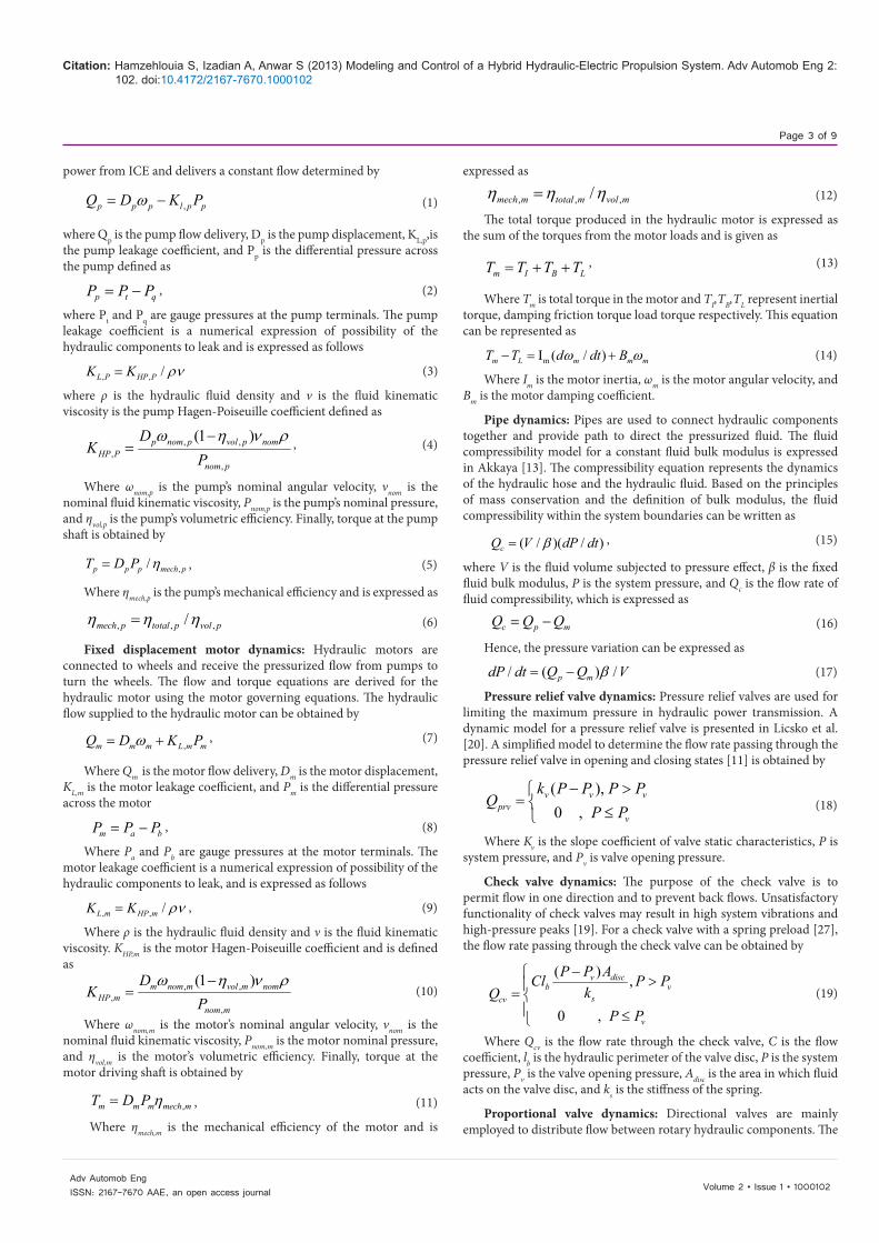
In this configuration, the vehicle is driven by the range extender at high engine efficiency. The overall hydraulic system can be connected as modules to represent the dynamic behavior. Block diagrams
of the hydraulic transmission system using MATLAB Simulink are demonstrated in figures 4 and 5. The model incorporates the mathematical governing equations of individual hydraulic circuit components. The bulk modulus unit generates the operating pressure of the system.
Figure 4 depicts a block diagram of the vehicle transmission system in the gasoline configuration. According to the figure 4, the range extender supplies power at a specific angular velocity to the main hydraulic pump. The hydraulic pump supplies pressurized hydraulic fluid to the proportional valve. The valve distributes the hydraulic fluid between the motors based on the driver speed command. The auxiliary motor captures the surplus energy of the flow. The auxiliary motor runs the electric generator which is coupled with and the generator converts the mechanical energy of the hydraulic fluid to electrical energy. The generated electrical energy is stored in a battery through the power electronics. The primary motor is coupled with the differential and runs the wheels.
Figure 5 displays the mathematical model of every hydraulic component in the transmission system. The flows and pressures are calculated for every hydraulic component. The data from the hydraulic circuit is utilized to calculate the flow of energy into the battery.
Electric configuration
The model of the all-electric configuration is represented similar to the gasoline configuration. In this configuration, the vehicle is driven
Hydraulic Pump ProportionalValve
Hydraulic Motor B
Hydraulic Motor A
Battery
CompressibilityCheck Valve
Pressure Relief Valve
P
P
ωmA
ωmB
Q mA Q mBQ CV
Qp
Qp
QPRV
ωp
Figure 4: Hydraulic transmission schematic diagram in gasoline configuration.
ωp/m kIB=
DODi =∫ IdtC0
ωp/m Q p/m
Q mA
Q p = Dpωp - kL,P Pp
Q m = Dmωm + kL,m Pm
Qc = QA,p - QmAT p = Dp ρ / η mech,p T m = Dm Pmη mech,m
T m - T L = Im (dωm/ dt) + Bm ωm
ωmAP
P
(dP/dt) = (β/V)QC
Figure 5: Simulink model of the hydraulic transmission system in gasoline configuration.
Battery Auxiliary Pump Compressibility Hydraulic Motor A
P
Pωp/m Q p/m ωmA
Q mA
Figure 6: Hydraulic transmission schematic diagram in all-electric configuration.
Citation: Hamzehlouia S, Izadian A, Anwar S (2013) Modeling and Control of a Hybrid Hydraulic-Electric Propulsion System. Adv Automob Eng 2: 102. doi:10.4172/2167-7670.1000102
Page 5 of 9
Volume 2 • Issue 1 • 1000102Adv Automob EngISSN: 2167-7670 AAE, an open access journal
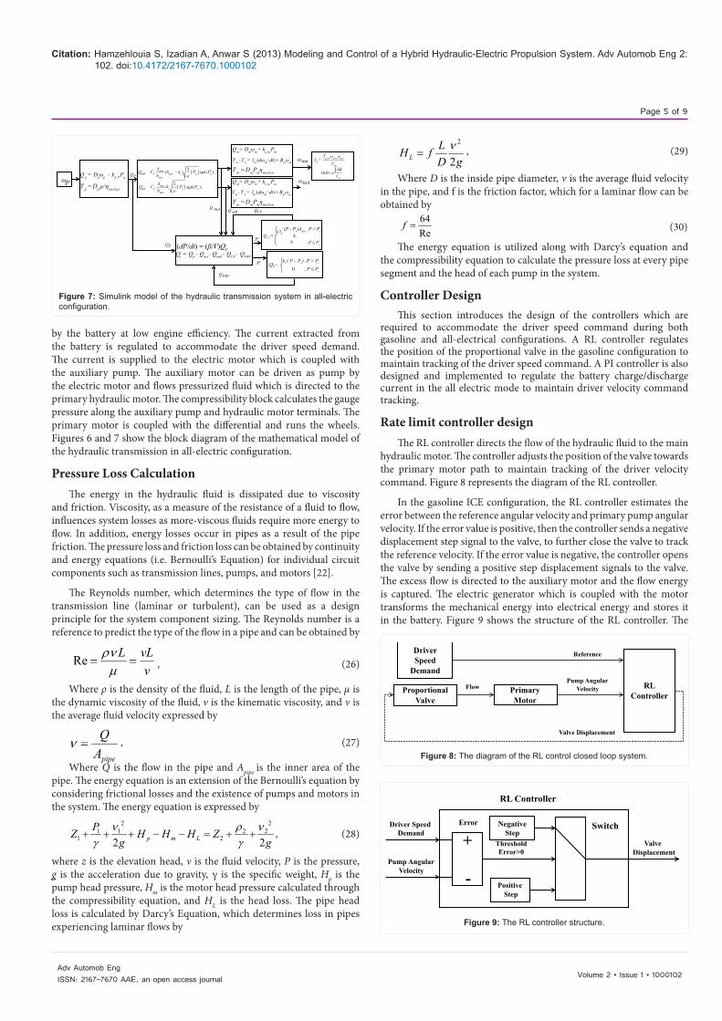
by the battery at low engine efficiency. The current extracted from the battery is regulated to accommodate the driver speed demand. The current is supplied to the electric motor which is coupled with the auxiliary pump. The auxiliary motor can be driven as pump by the electric motor and flows pressurized fluid which is directed to the primary hydraulic motor. The compressibility block calculates the gauge pressure along the auxiliary pump and hydraulic motor terminals. The primary motor is coupled with the differential and runs the wheels. Figures 6 and 7 show the block diagram of the mathematical model of the hydraulic transmission in all-electric configuration.
Pressure Loss CalculationThe energy in the hydraulic fluid is dissipated due to viscosity
and friction. Viscosity, as a measure of the resistance of a fluid to flow, influences system losses as more-viscous fluids require more energy to flow. In addition, energy losses occur in pipes as a result of the pipe friction. The pressure loss and friction loss can be obtained by continuity and energy equations (i.e. Bernoulli’s Equation) for individual circuit components such as transmission lines, pumps, and motors [22].
The Reynolds number, which determines the type of flow in the transmission line (laminar or turbulent), can be used as a design principle for the system component sizing. The Reynolds number is a reference to predict the type of the flow in a pipe and can be obtained by
Re L vLv
ρνµ
= = , (26)
Where ρ is the density of the fluid, L is the length of the pipe, μ is the dynamic viscosity of the fluid, v is the kinematic viscosity, and ν is the average fluid velocity expressed by
pipe
QA
ν = , (27)
Where Q is the flow in the pipe and Apipe is the inner area of the pipe. The energy equation is an extension of the Bernoulli’s equation by considering frictional losses and the existence of pumps and motors in the system. The energy equation is expressed by
2 21 1 2 2
1 22 2p m LPZ H H H Z
g gν ρ ν
γ γ+ + + − − = + + , (28)
where z is the elevation head, ν is the fluid velocity, P is the pressure, g is the acceleration due to gravity, γ is the specific weight, Hp is the pump head pressure, Hm is the motor head pressure calculated through the compressibility equation, and HL is the head loss. The pipe head loss is calculated by Darcy’s Equation, which determines loss in pipes experiencing laminar flows by
2
2LLH fD gν
= , (29)
Where D is the inside pipe diameter, v is the average fluid velocity in the pipe, and f is the friction factor, which for a laminar flow can be obtained by
64Re
f = (30)
The energy equation is utilized along with Darcy’s equation and the compressibility equation to calculate the pressure loss at every pipe segment and the head of each pump in the system.
Controller DesignThis section introduces the design of the controllers which are
required to accommodate the driver speed command during both gasoline and all-electrical configurations. A RL controller regulates the position of the proportional valve in the gasoline configuration to maintain tracking of the driver speed command. A PI controller is also designed and implemented to regulate the battery charge/discharge current in the all electric mode to maintain driver velocity command tracking.
Rate limit controller designThe RL controller directs the flow of the hydraulic fluid to the main
hydraulic motor. The controller adjusts the position of the valve towards the primary motor path to maintain tracking of the driver velocity command. Figure 8 represents the diagram of the RL controller.
In the gasoline ICE configuration, the RL controller estimates the error between the reference angular velocity and primary pump angular velocity. If the error value is positive, then the controller sends a negative displacement step signal to the valve, to further close the valve to track the reference velocity. If the error value is negative, the controller opens the valve by sending a positive step displacement signals to the valve. The excess flow is directed to the auxiliary motor and the flow energy is captured. The electric generator which is coupled with the motor transforms the mechanical energy into electrical energy and stores it in the battery. Figure 9 shows the structure of the RL controller. The
Q mA
ωp
QP
QP
QPRV
QV
Q CV
P
P
Q p = Dpωp - kL,P Pp
T p = Dp ρ/ η mech,p
Q m = Dmωm + kL,m Pm
Q m = Dmωm + kL,m Pm
T m = Dm Pmη mech,m
T m = Dm Pmη mech,m
T m - T L = Im (dωm/ dt) + Bm ωm
T m - T L = Im (dωm/ dt) + Bm ωm
QCVQ mB
ωmA
ωmB
Qc = Qp - QmA- QmB - QCV- QPRV
(dP/dt) = (β/V)QC
DODi = ∫ IdtC0
IB =Tp/m ωp/m η gen
VB
=
=
Clb(P - Pv)Adisc ,P > Pv
ks
,P ≤ Pv
, P ≤ Pv
0
0kv ( P - Pv) ,P > Pv
QmA
QmB Cd
Cd
Amax
Amax
hmax
hmax
hmax hi-( )
hi
2ρ
Pp Ppsgn( ),
2ρ
Pp Ppsgn( ),
Figure 7: Simulink model of the hydraulic transmission system in all-electric configuration.
DriverSpeed
Demand
ProportionalValve
PrimaryMotor
RLController
FlowPump Angular
Velocity
Reference
Valve Displacement
Figure 8: The diagram of the RL control closed loop system.
RL Controller
Driver SpeedDemand
Pump AngularVelocity
PositiveStep
ValveDisplacement
SwitchNegativeStep
Error
ThresholdError>0
+
-
Figure 9: The RL controller structure.
Citation: Hamzehlouia S, Izadian A, Anwar S (2013) Modeling and Control of a Hybrid Hydraulic-Electric Propulsion System. Adv Automob Eng 2: 102. doi:10.4172/2167-7670.1000102
Page 6 of 9
Volume 2 • Issue 1 • 1000102Adv Automob EngISSN: 2167-7670 AAE, an open access journal
step values are designed to maintain system stability while both fast response and error mitigation criteria are fulfilled.
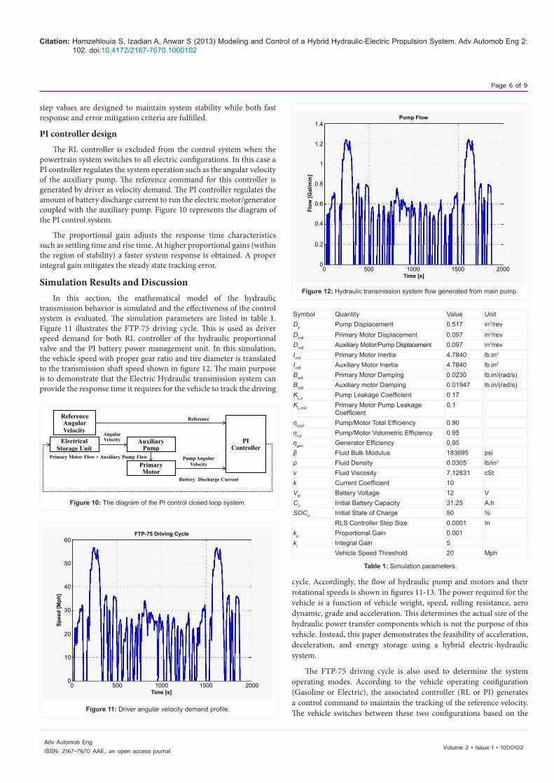
PI controller design
The RL controller is excluded from the control system when the powertrain system switches to all electric configurations. In this case a PI controller regulates the system operation such as the angular velocity of the auxiliary pump. The reference command for this controller is generated by driver as velocity demand. The PI controller regulates the amount of battery discharge current to run the electric motor/generator coupled with the auxiliary pump. Figure 10 represents the diagram of the PI control system.
The proportional gain adjusts the response time characteristics such as settling time and rise time. At higher proportional gains (within the region of stability) a faster system response is obtained. A proper integral gain mitigates the steady state tracking error.
Simulation Results and DiscussionIn this section, the mathematical model of the hydraulic
transmission behavior is simulated and the effectiveness of the control system is evaluated. The simulation parameters are listed in table 1. Figure 11 illustrates the FTP-75 driving cycle. This is used as driver speed demand for both RL controller of the hydraulic proportional valve and the PI battery power management unit. In this simulation, the vehicle speed with proper gear ratio and tire diameter is translated to the transmission shaft speed shown in figure 12. The main purpose is to demonstrate that the Electric Hydraulic transmission system can provide the response time it requires for the vehicle to track the driving
cycle. Accordingly, the flow of hydraulic pump and motors and their rotational speeds is shown in figures 11-13. The power required for the vehicle is a function of vehicle weight, speed, rolling resistance, aero dynamic, grade and acceleration. This determines the actual size of the hydraulic power transfer components which is not the purpose of this vehicle. Instead, this paper demonstrates the feasibility of acceleration, deceleration, and energy storage using a hybrid electric-hydraulic system.
The FTP-75 driving cycle is also used to determine the system operating modes. According to the vehicle operating configuration (Gasoline or Electric), the associated controller (RL or PI) generates a control command to maintain the tracking of the reference velocity. The vehicle switches between these two configurations based on the
ReferenceAngularVelocity
AngularVelocityElectrical
Storage UnitAuxiliary
Pump
PrimaryMotor
PIController
Primary Motor Flow + Auxiliary Pump Flow
Battery Discharge Current
Pump AngularVelocity
Reference
Figure 10: The diagram of the PI control closed loop system.
FTP-75 Driving Cycle
Spee
d [M
ph]
Time [s]
60
50
40
30
20
10
00 500 1000 1500 2000
Figure 11: Driver angular velocity demand profile.
Pump Flow
Flow
[Gal
/min
]
Time [s]
1.4
1.2
1
0.8
0.6
0.4
0.2
00 500 1000 1500 2000
Figure 12: Hydraulic transmission system flow generated from main pump.
Symbol Quantity Value UnitDp Pump Displacement 0.517 in3/revDmA Primary Motor Displacement 0.097 in3/revDmB Auxiliary Motor/Pump Displacement 0.097 in3/revImA Primary Motor Inertia 4.7840 lb.in2
ImB Auxiliary Motor Inertia 4.7840 lb.in2
BmA Primary Motor Damping 0.0230 lb.in/(rad/s)BmB Auxiliary motor Damping 0.01947 lb.in/(rad/s)KL,p Pump Leakage Coefficient 0.17KL,mA Primary Motor Pump Leakage
Coefficient0.1
ηtotal Pump/Motor Total Efficiency 0.90ηvol Pump/Motor Volumetric Efficiency 0.95ηgen Generator Efficiency 0.95β Fluid Bulk Modulus 183695 psiρ Fluid Density 0.0305 lb/in3
ν Fluid Viscosity 7.12831 cStk Current Coefficient 10VB Battery Voltage 12 VC0 Initial Battery Capacity 31.25 A.hSOC0 Initial State of Charge 50 %
RLS Controller Step Size 0.0001 Inkp Proportional Gain 0.001ki Integral Gain 5
Vehicle Speed Threshold 20 Mph
Table 1: Simulation parameters.
Citation: Hamzehlouia S, Izadian A, Anwar S (2013) Modeling and Control of a Hybrid Hydraulic-Electric Propulsion System. Adv Automob Eng 2: 102. doi:10.4172/2167-7670.1000102
Page 7 of 9
Volume 2 • Issue 1 • 1000102Adv Automob EngISSN: 2167-7670 AAE, an open access journal
ICE efficiency threshold which is correlated with the vehicle speed. In general, ICE engines are very inefficient in lower speeds. Hence, the system is switched to all-electric (engine–off) if the engine efficiency drops below a certain efficiency threshold. If the engine efficiency stays above a threshold and there is a need for the extra power, the vehicle switches to gasoline ICE configuration. The efficiency threshold in this paper is adjusted to the point at which the vehicle speed is 20 Mph. The chosen vehicle for simulation is a VW Golf whose engine power rating was scaled down to match the prime mover power in the future experimental hardware-in-loop bench. Other vehicle parameters were also scaled down accordingly.
Figure 11 shows the flow passing through the main pump when the FTP-75 driving cycle of figure 10 is applied. According to figure 11, when the vehicle speed is lower than 20 Mph, the engine was shut down and the main pump was excluded from the hydraulic circuit. When the engine efficiency exceeded a threshold value, the system switched to ICE gasoline configuration. Consequently, the main pump started circulating the hydraulic flow in the system. Occasionally, in vehicle deceleration, the engine efficiency fell below the target efficiency and the pump was bypassed to run in all-electric mode.
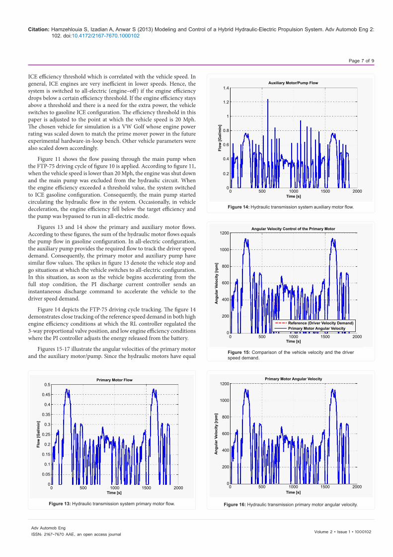
Figures 13 and 14 show the primary and auxiliary motor flows. According to these figures, the sum of the hydraulic motor flows equals the pump flow in gasoline configuration. In all-electric configuration, the auxiliary pump provides the required flow to track the driver speed demand. Consequently, the primary motor and auxiliary pump have similar flow values. The spikes in figure 13 denote the vehicle stop and go situations at which the vehicle switches to all-electric configuration. In this situation, as soon as the vehicle begins accelerating from the full stop condition, the PI discharge current controller sends an instantaneous discharge command to accelerate the vehicle to the driver speed demand.
Figure 14 depicts the FTP-75 driving cycle tracking. The figure 14 demonstrates close tracking of the reference speed demand in both high engine efficiency conditions at which the RL controller regulated the 3-way proportional valve position, and low engine efficiency conditions where the PI controller adjusts the energy released from the battery.
Figures 15-17 illustrate the angular velocities of the primary motor and the auxiliary motor/pump. Since the hydraulic motors have equal
Primary Motor Flow
Flow
[Gal
/min
]
Time [s]
0.5
0.45
0.4
0.35
0.3
0.25
0.2
0.15
0.1
0.05
00 500 1000 1500 2000
Figure 13: Hydraulic transmission system primary motor flow.
Auxiliary Motor/Pump Flow
Flow
[Gal
/min
]
Time [s]
1.4
1.2
1
0.8
0.6
0.4
0.2
0 0 500 1000 1500 2000
Figure 14: Hydraulic transmission system auxiliary motor flow.
Angular Velocity Control of the Primary Motor
Ang
ular
Vel
ocity
[rpm
]
Time [s]
Reference (Driver Velocity Demand)Primary Motor Angular Velocity
1200
1000
800
600
400
200
00 500 1000 1500 2000
Figure 15: Comparison of the vehicle velocity and the driver speed demand.
Primary Motor Angular Velocity
Ang
ular
Vel
ocity
[rpm
]
Time [s]
1200
1000
800
600
400
200
0 0 500 1000 1500 2000
Figure 16: Hydraulic transmission primary motor angular velocity.
Citation: Hamzehlouia S, Izadian A, Anwar S (2013) Modeling and Control of a Hybrid Hydraulic-Electric Propulsion System. Adv Automob Eng 2: 102. doi:10.4172/2167-7670.1000102
Page 8 of 9
Volume 2 • Issue 1 • 1000102Adv Automob EngISSN: 2167-7670 AAE, an open access journal
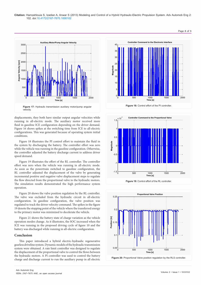
displacements, they both have similar output angular velocities while running in all-electric mode. The auxiliary motor received more fluid in gasoline ICE configuration depending on the driver demand. Figure 16 shows spikes at the switching time from ICE to all-electric configurations. This was generated because of operating system initial conditions.
Figure 18 illustrates the PI control effort to maintain the fluid in the system by discharging the battery. The controller effort was zero while the vehicle was running in the gasoline configuration. Otherwise, the controller adjusted the battery discharge current to address driver speed demand.
Figure 19 illustrates the effort of the RL controller. The controller effort was zero when the vehicle was running in all-electric mode. As soon as the powertrain switched to gasoline configuration, the RL controller adjusted the displacement of the valve by generating incremental positive and negative valve displacement steps to regulate the flow directed from the proportional valve to the hydraulic motors. The simulation results demonstrated the high performance system operation.
Figure 20 shows the valve position regulation by the RL controller. The valve was excluded from the hydraulic circuit in all-electric configuration. In gasoline configuration, the valve position was regulated to track the driver velocity command. The spikes in the figure 19 denote the stopping point of the vehicle where the transferred energy to the primary motor was minimized to decelerate the vehicle.
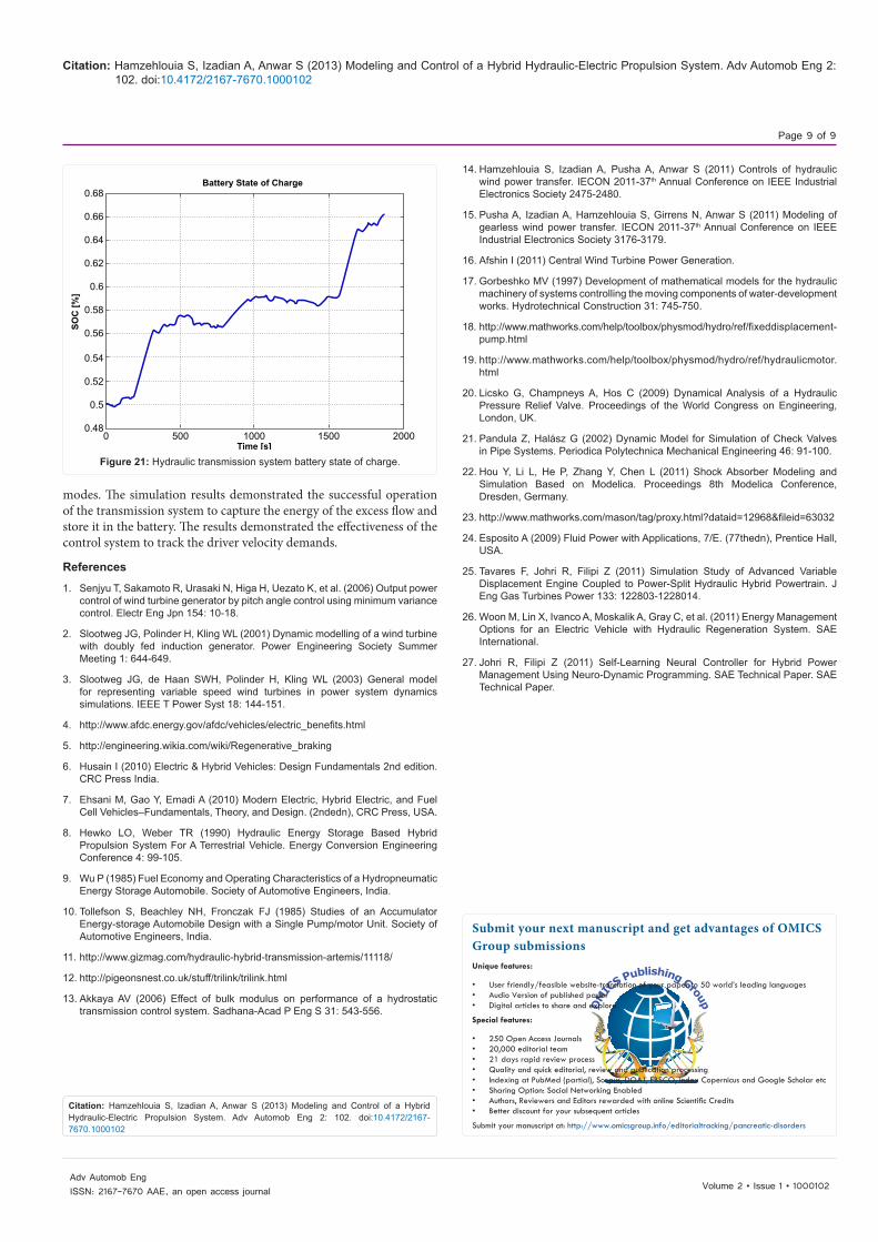
Figure 21 shows the battery state of charge variation as the vehicle operation modes change. As it illustrates, the SOC increased when the ICE was running in the proposed driving cycle of figure 10 and the battery was discharged while running in all-electric configuration.
ConclusionThis paper introduced a hybrid electric-hydraulic regenerative
gearless driveline system. Dynamic models of the hydraulic transmission system were obtained. A rate limit controller was designed to regulate the displacement of the proportional valve to control the flows between the hydraulic motors. A PI controller was used to control the battery charge and discharge current to run the auxiliary pump in all electric
Proportional Valve Position
Posi
tion
[in]
Time [s]
0.25
0.2
0.15
0.1
0.050 500 1000 1500 2000
Figure 20: Proportional Valve position regulation by the RLS controller.
Auxiliary Motor/Pump Angular Velocity
Ang
ular
Vel
ocity
[rpm
]
Time [s]
3000
2500
2000
1500
1000
500
00 500 1000 1500 2000
Figure 17: Hydraulic transmission auxiliary motor/pump angular velocity.
Controller Command to the Electronic Interface
Mag
nitu
de
Time [s]
40
35
30
25
20
15
10
5
00 500 1000 1500 2000
Figure 18: Control effort of the PI controller.
Controller Command to the Proportional Valve
Mag
nitu
de
Time [s]
1.5
1
0.5
0
-0.5
-1
-1.50 500 1000 1500 2000
x 10-4
Figure 19: Control effort of the RL controller.
Citation: Hamzehlouia S, Izadian A, Anwar S (2013) Modeling and Control of a Hybrid Hydraulic-Electric Propulsion System. Adv Automob Eng 2: 102. doi:10.4172/2167-7670.1000102
Page 9 of 9
Volume 2 • Issue 1 • 1000102Adv Automob EngISSN: 2167-7670 AAE, an open access journal
modes. The simulation results demonstrated the successful operation of the transmission system to capture the energy of the excess flow and store it in the battery. The results demonstrated the effectiveness of the control system to track the driver velocity demands.
References
1. Senjyu T, Sakamoto R, Urasaki N, Higa H, Uezato K, et al. (2006) Output power control of wind turbine generator by pitch angle control using minimum variance control. Electr Eng Jpn 154: 10-18.
2. Slootweg JG, Polinder H, Kling WL (2001) Dynamic modelling of a wind turbine with doubly fed induction generator. Power Engineering Society Summer Meeting 1: 644-649.
3. Slootweg JG, de Haan SWH, Polinder H, Kling WL (2003) General model for representing variable speed wind turbines in power system dynamics simulations. IEEE T Power Syst 18: 144-151.
4. http://www.afdc.energy.gov/afdc/vehicles/electric_benefits.html
5. http://engineering.wikia.com/wiki/Regenerative_braking
6. Husain I (2010) Electric & Hybrid Vehicles: Design Fundamentals 2nd edition. CRC Press India.
7. Ehsani M, Gao Y, Emadi A (2010) Modern Electric, Hybrid Electric, and Fuel Cell Vehicles–Fundamentals, Theory, and Design. (2ndedn), CRC Press, USA.
8. Hewko LO, Weber TR (1990) Hydraulic Energy Storage Based Hybrid Propulsion System For A Terrestrial Vehicle. Energy Conversion Engineering Conference 4: 99-105.
9. Wu P (1985) Fuel Economy and Operating Characteristics of a Hydropneumatic Energy Storage Automobile. Society of Automotive Engineers, India.
10. Tollefson S, Beachley NH, Fronczak FJ (1985) Studies of an Accumulator Energy-storage Automobile Design with a Single Pump/motor Unit. Society of Automotive Engineers, India.
11. http://www.gizmag.com/hydraulic-hybrid-transmission-artemis/11118/
12. http://pigeonsnest.co.uk/stuff/trilink/trilink.html
13. Akkaya AV (2006) Effect of bulk modulus on performance of a hydrostatic transmission control system. Sadhana-Acad P Eng S 31: 543-556.
Battery State of Charge
SOC
[%]
Time [s]
0.68
0.66
0.64
0.62
0.6
0.58
0.56
0.54
0.52
0.5
0.480 500 1000 1500 2000
Figure 21: Hydraulic transmission system battery state of charge.
14. Hamzehlouia S, Izadian A, Pusha A, Anwar S (2011) Controls of hydraulic wind power transfer. IECON 2011-37th Annual Conference on IEEE Industrial Electronics Society 2475-2480.
15. Pusha A, Izadian A, Hamzehlouia S, Girrens N, Anwar S (2011) Modeling of gearless wind power transfer. IECON 2011-37th Annual Conference on IEEE Industrial Electronics Society 3176-3179.
16. Afshin I (2011) Central Wind Turbine Power Generation.
17. Gorbeshko MV (1997) Development of mathematical models for the hydraulic machinery of systems controlling the moving components of water-development works. Hydrotechnical Construction 31: 745-750.
18. http://www.mathworks.com/help/toolbox/physmod/hydro/ref/fixeddisplacement-pump.html
19. http://www.mathworks.com/help/toolbox/physmod/hydro/ref/hydraulicmotor.html
20. Licsko G, Champneys A, Hos C (2009) Dynamical Analysis of a Hydraulic Pressure Relief Valve. Proceedings of the World Congress on Engineering, London, UK.
21. Pandula Z, Halász G (2002) Dynamic Model for Simulation of Check Valves in Pipe Systems. Periodica Polytechnica Mechanical Engineering 46: 91-100.
22. Hou Y, Li L, He P, Zhang Y, Chen L (2011) Shock Absorber Modeling and Simulation Based on Modelica. Proceedings 8th Modelica Conference, Dresden, Germany.
23. http://www.mathworks.com/mason/tag/proxy.html?dataid=12968&fileid=63032
24. Esposito A (2009) Fluid Power with Applications, 7/E. (77thedn), Prentice Hall, USA.
25. Tavares F, Johri R, Filipi Z (2011) Simulation Study of Advanced Variable Displacement Engine Coupled to Power-Split Hydraulic Hybrid Powertrain. J Eng Gas Turbines Power 133: 122803-1228014.
26. Woon M, Lin X, Ivanco A, Moskalik A, Gray C, et al. (2011) Energy Management Options for an Electric Vehicle with Hydraulic Regeneration System. SAE International.
27. Johri R, Filipi Z (2011) Self-Learning Neural Controller for Hybrid Power Management Using Neuro-Dynamic Programming. SAE Technical Paper. SAE Technical Paper.
Submit your next manuscript and get advantages of OMICS Group submissionsUnique features:
• Userfriendly/feasiblewebsite-translationofyourpaperto50world’sleadinglanguages• AudioVersionofpublishedpaper• Digitalarticlestoshareandexplore
Special features:
• 250OpenAccessJournals• 20,000editorialteam• 21daysrapidreviewprocess• Qualityandquickeditorial,reviewandpublicationprocessing• IndexingatPubMed(partial),Scopus,DOAJ,EBSCO,IndexCopernicusandGoogleScholaretc• SharingOption:SocialNetworkingEnabled• Authors,ReviewersandEditorsrewardedwithonlineScientificCredits• Betterdiscountforyoursubsequentarticles
Submityourmanuscriptat:http://www.omicsgroup.info/editorialtracking/pancreatic-disorders
Citation: Hamzehlouia S, Izadian A, Anwar S (2013) Modeling and Control of a Hybrid Hydraulic-Electric Propulsion System. Adv Automob Eng 2: 102. doi:10.4172/2167-7670.1000102


![Advances in Automobile Hamzehlouia et al., Engineeringaizadian/index_files/Papers/J-6.pdf · Advances in Automobile Engineering. Hamzehlouia et al., ... [9,10] report 79% fuel economy](https://img.pdfslide.net/doc/110x75/5ab347497f8b9aea528e285f/advances-in-automobile-hamzehlouia-et-al-aizadianindexfilespapersj-6pdfadvances.jpg)