Embed Size (px)
Citation preview

Advances in High
Voltage Converter
Modulator and
Performance
Presented at the
Accelerator Advisory Committee Review
David E. Anderson, HV, PP & MS Manager, Research Accelerator Division
May 2013
2 SNS AAC 2013 – Advances in High Voltage Converter Modulator and Performance
IGBT SWITCH PLATE ASS'Y. (3X)
SAFETY ENCLOSURE
B PHASE SHOWN
CRes
CRes
CRes
A
B
C
5th Harmonic Trap 7th Harmonic Trap
13.8 kV : 2100 Vdelta wye
50 mH
OUTSIDE FILTERS AND TRANSFORMER
1.5 MVA
FUSEDDISCONNECT
BUILDINGINTERFACE
Fuse / Contactor
4 mH450 A
4 mH450 A
SCR CONTROLLER
+/-1300 V, 450 A
DC+
DC-
DC+
DC-
0.112 F
0.112 F
40X RG-8
40X RG-8
RdeQ
2X 0.03 uF500 pF
HV divider
CT
OIL-FILLED MODULATOR TANK
CONTROLRACK &
CONTROLLER
CAP RACK
Modulators provide pulsed power to high power RF klystrons
using 20 kHz switching with IGBTs
• Provides up to 135 kV, 1.35 ms pulses at 60 Hz to amplify RF to 5 MW
• 3 phases employed to increase output ripple frequency
– Minimizes output filter requirements
– Minimizes fault energy available to klystron
• Powers multiple klystrons up to 11 MW peak power
• Currently there is up to a 5% pulse droop operating in open-loop
3 SNS AAC 2013 – Advances in High Voltage Converter Modulator and Performance
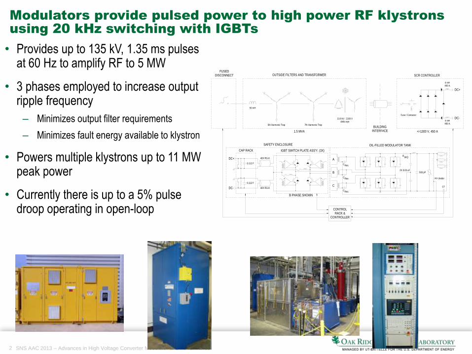
15 Modulators in 3 different configurations power 92 klystrons
to support operation of the Linac
• 15 modulators: 3 - DTL, 4 - CCL, 8 – SCL (1 added 2008)
• Multiple HVCM/Klystron Configurations
• 690,000 combined operational hours on all modulators
115 kV 125 kV ≤135 kV 71 kV 75 kV
DTL (8.5-10.6 MW peak)
CCL (8.4-9.1 MW peak)
SCL (8.0-8.8 MW peak)
4 SNS AAC 2013 – Advances in High Voltage Converter Modulator and Performance
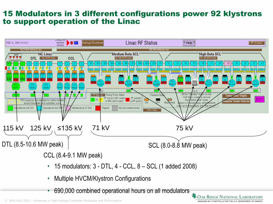
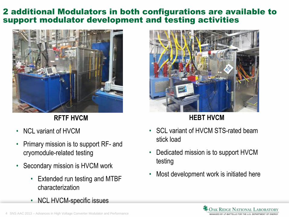
2 additional Modulators in both configurations are available to
support modulator development and testing activities
RFTF HVCM
• NCL variant of HVCM
• Primary mission is to support RF- and
cryomodule-related testing
• Secondary mission is HVCM work
• Extended run testing and MTBF
characterization
• NCL HVCM-specific issues
HEBT HVCM
• SCL variant of HVCM STS-rated beam
stick load
• Dedicated mission is to support HVCM
testing
• Most development work is initiated here
5 SNS AAC 2013 – Advances in High Voltage Converter Modulator and Performance
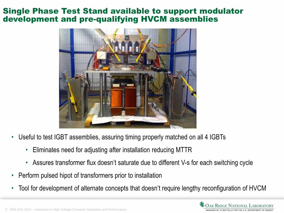
Single Phase Test Stand available to support modulator
development and pre-qualifying HVCM assemblies
• Useful to test IGBT assemblies, assuring timing properly matched on all 4 IGBTs
• Eliminates need for adjusting after installation reducing MTTR
• Assures transformer flux doesn’t saturate due to different V-s for each switching cycle
• Perform pulsed hipot of transformers prior to installation
• Tool for development of alternate concepts that doesn’t require lengthy reconfiguration of HVCM
6 SNS AAC 2013 – Advances in High Voltage Converter Modulator and Performance
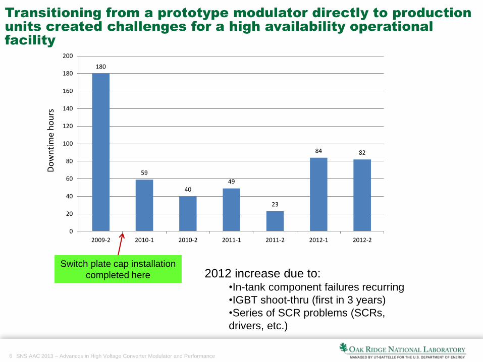
Switch plate cap installation
completed here 2012 increase due to:•In-tank component failures recurring
•IGBT shoot-thru (first in 3 years)
•Series of SCR problems (SCRs,
drivers, etc.)
Transitioning from a prototype modulator directly to production
units created challenges for a high availability operational
facility
180
59
4049
23
84 82
0
20
40
60
80
100
120
140
160
180
200
2009-2 2010-1 2010-2 2011-1 2011-2 2012-1 2012-2
Do
wn
tim
e h
ou
rs
7 SNS AAC 2013 – Advances in High Voltage Converter Modulator and Performance
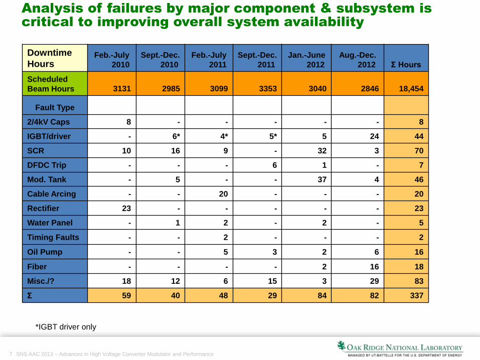
Analysis of failures by major component & subsystem is
critical to improving overall system availability
Downtime
HoursFeb.-July
2010
Sept.-Dec.
2010
Feb.-July
2011
Sept.-Dec.
2011
Jan.-June
2012
Aug.-Dec.
2012 Σ Hours
Scheduled
Beam Hours 3131 2985 3099 3353 3040 2846 18,454
Fault Type
2/4kV Caps 8 - - - - - 8
IGBT/driver - 6* 4* 5* 5 24 44
SCR 10 16 9 - 32 3 70
DFDC Trip - - - 6 1 - 7
Mod. Tank - 5 - - 37 4 46
Cable Arcing - - 20 - - - 20
Rectifier 23 - - - - - 23
Water Panel - 1 2 - 2 - 5
Timing Faults - - 2 - - - 2
Oil Pump - - 5 3 2 6 16
Fiber - - - - 2 16 18
Misc./? 18 12 6 15 3 29 83
Σ 59 40 48 29 84 82 337
*IGBT driver only
8 SNS AAC 2013 – Advances in High Voltage Converter Modulator and Performance
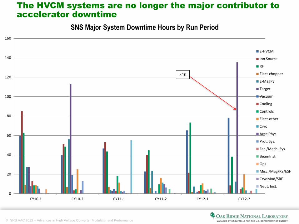
SNS Major System Downtime Hours by Run Period
The HVCM systems are no longer the major contributor to
accelerator downtime
0
20
40
60
80
100
120
140
160
CY10-1 CY10-2 CY11-1 CY11-2 CY12-1 CY12-2
E-HVCM
Ion Source
RF
Elect-chopper
E-MagPS
Target
Vacuum
Cooling
Controls
Elect-other
Cryo
AccelPhys
Prot. Sys.
Fac./Mech. Sys.
BeamInstr
Ops
Misc./Mag/RS/ESH
CryoMod/SRF
Neut. Inst.
×10
9 SNS AAC 2013 – Advances in High Voltage Converter Modulator and Performance
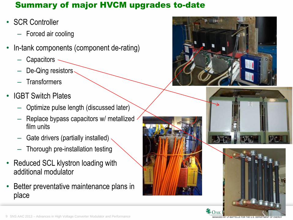
Summary of major HVCM upgrades to-date
• SCR Controller
– Forced air cooling
• In-tank components (component de-rating)
– Capacitors
– De-Qing resistors
– Transformers
• IGBT Switch Plates
– Optimize pulse length (discussed later)
– Replace bypass capacitors w/ metallizedfilm units
– Gate drivers (partially installed)
– Thorough pre-installation testing
• Reduced SCL klystron loading with additional modulator
• Better preventative maintenance plans in place
10 SNS AAC 2013 – Advances in High Voltage Converter Modulator and Performance
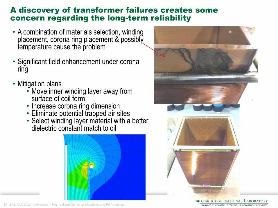
A discovery of transformer failures creates some
concern regarding the long-term reliability
• A combination of materials selection, winding placement, corona ring placement & possibly temperature cause the problem
• Significant field enhancement under corona ring
• Mitigation plans• Move inner winding layer away from
surface of coil form• Increase corona ring dimension• Eliminate potential trapped air sites• Select winding layer material with a better
dielectric constant match to oil
11 SNS AAC 2013 – Advances in High Voltage Converter Modulator and Performance
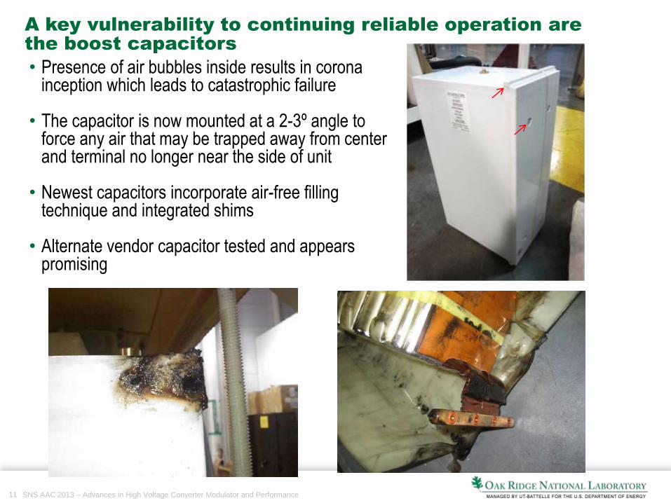
A key vulnerability to continuing reliable operation are
the boost capacitors
• Presence of air bubbles inside results in corona inception which leads to catastrophic failure
• The capacitor is now mounted at a 2-3º angle to force any air that may be trapped away from center and terminal no longer near the side of unit
• Newest capacitors incorporate air-free filling technique and integrated shims
• Alternate vendor capacitor tested and appears promising
12 SNS AAC 2013 – Advances in High Voltage Converter Modulator and Performance
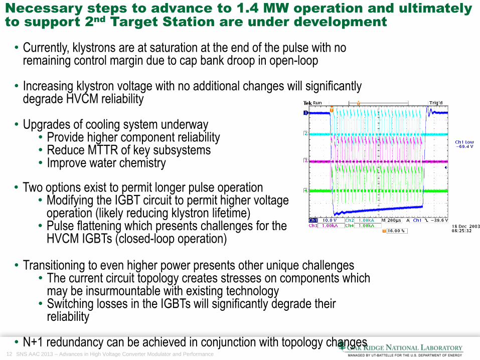
Necessary steps to advance to 1.4 MW operation and ultimately
to support 2nd
Target Station are under development
• Currently, klystrons are at saturation at the end of the pulse with no remaining control margin due to cap bank droop in open-loop
• Increasing klystron voltage with no additional changes will significantly degrade HVCM reliability
• Upgrades of cooling system underway• Provide higher component reliability• Reduce MTTR of key subsystems• Improve water chemistry
• Transitioning to even higher power presents other unique challenges• The current circuit topology creates stresses on components which
may be insurmountable with existing technology• Switching losses in the IGBTs will significantly degrade their
reliability
• N+1 redundancy can be achieved in conjunction with topology changes
• Two options exist to permit longer pulse operation• Modifying the IGBT circuit to permit higher voltage
operation (likely reducing klystron lifetime)• Pulse flattening which presents challenges for the
HVCM IGBTs (closed-loop operation)
13 SNS AAC 2013 – Advances in High Voltage Converter Modulator and Performance
0
200
400
600
800
1000
1200
1400
0 2 4 6 8 10 12 14 16 18 20
VC
E O
verv
olt
age
, V
Duration of last diagonal pair "runt" pulse, ms
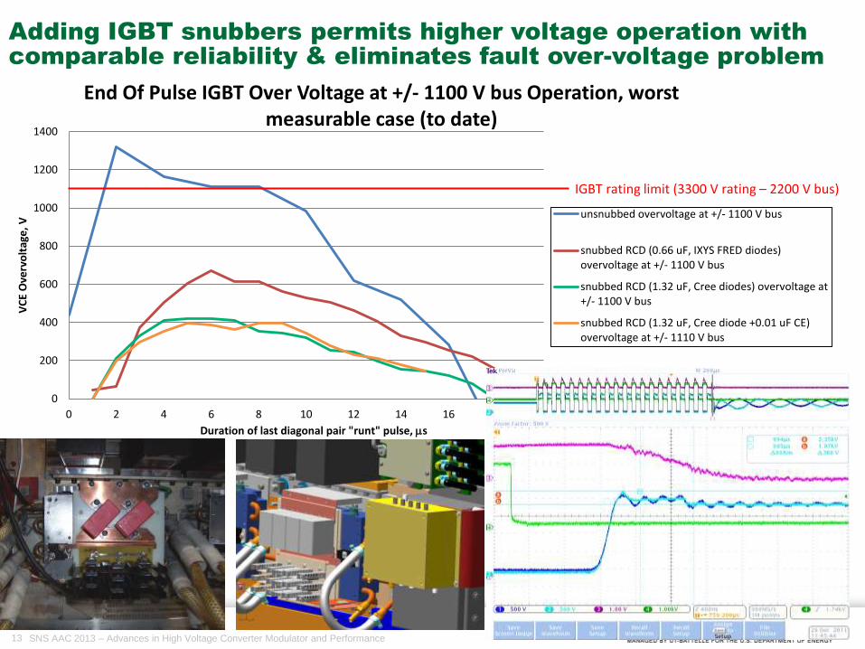
End Of Pulse IGBT Over Voltage at +/- 1100 V bus Operation, worst measurable case (to date)
unsnubbed overvoltage at +/- 1100 V bus
snubbed RCD (0.66 uF, IXYS FRED diodes)overvoltage at +/- 1100 V bus
snubbed RCD (1.32 uF, Cree diodes) overvoltage at+/- 1100 V bus
snubbed RCD (1.32 uF, Cree diode +0.01 uF CE)overvoltage at +/- 1110 V bus
IGBT rating limit (3300 V rating – 2200 V bus)
Adding IGBT snubbers permits higher voltage operation with
comparable reliability & eliminates fault over-voltage problem

14 SNS AAC 2013 – Advances in High Voltage Converter Modulator and Performance
DC bus ripple creates problems for the snubber resistor
which tries to track bus fluctuations
• Snubber capacitor tracks bus fluctuations through the bleed resistor – energy exceeds ratings of the water-cooled resistor
• Air-cooled resistor will not tolerate the average power dissipation requirements for the snubber application
• Attempting to resolve by
– Testing to understand bus ringing to minimize or eliminate it
– Identifying resistor or resistors that handle both the energy and power dissipation – EBG helpful
Large cap bank ringing (green)
vs. switch plate bus ringing (others)
-50
-40
-30
-20
-10
0
10
20
30
40
50
0.0E+00 2.0E-04 4.0E-04 6.0E-04 8.0E-04 1.0E-03 1.2E-03 1.4E-03
C phase snubber R current
B phase snubber R current
A phase snubber R current
15 SNS AAC 2013 – Advances in High Voltage Converter Modulator and Performance
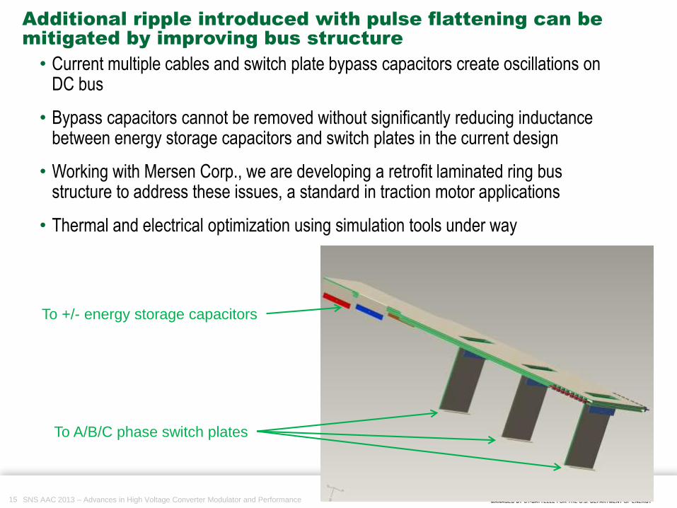
Additional ripple introduced with pulse flattening can be
mitigated by improving bus structure
• Current multiple cables and switch plate bypass capacitors create oscillations on DC bus
• Bypass capacitors cannot be removed without significantly reducing inductance between energy storage capacitors and switch plates in the current design
• Working with Mersen Corp., we are developing a retrofit laminated ring bus structure to address these issues, a standard in traction motor applications
• Thermal and electrical optimization using simulation tools under way
To +/- energy storage capacitors
To A/B/C phase switch plates

16 SNS AAC 2013 – Advances in High Voltage Converter Modulator and Performance
Output Voltage= 61.8 kV
Bus Voltage= +/- 1004 V
FM = 20 kHz to 22 kHz
PSM = 95% to 100%
∆𝑉𝑑𝑟𝑜𝑜𝑝 = 304 V/ms (0.5%
vs. 3-5% currently
∆𝑉𝑟𝑖𝑝𝑝𝑙𝑒 = 664 V
-5 0 5 10 15 20
x 10-4
-7
-6.8
-6.6
-6.4
-6.2
-6
-5.8
-5.6
-5.4
-5.2x 10
4
X: 0.000945
Y: -6.644e+004
time (SECS)
Out
put
Vol
tage
(V
OLT
S)
X: 0.0009595
Y: -6.716e+004
Phase Shift and Frequency Modulation achieves pulse
flattening and has been demonstrated at 60 Hz full power
59
60
61
62
63
90 92 94 96 98 100V
out(k
V)
PM (%)
Vout(kV) vs PM(%) @ fixed DC bus @ 1000 V bus
59
60
61
62
63
17 18 19 20 21 22 23
Vou
t(k
V)
fsw (kHz)
Vout(kV) vs fsw(kHz) @ 1000 V busImproved adjustable output filter components on order to reduce ripple and “tune” rise time.
17 SNS AAC 2013 – Advances in High Voltage Converter Modulator and Performance
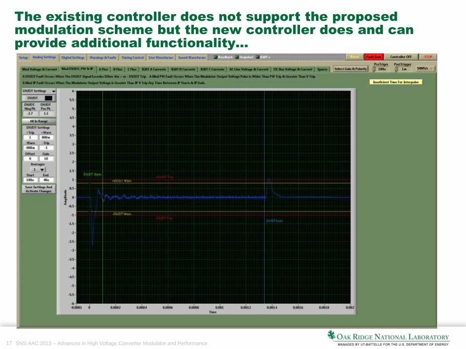
The existing controller does not support the proposed
modulation scheme but the new controller does and can
provide additional functionality…
18 SNS AAC 2013 – Advances in High Voltage Converter Modulator and Performance
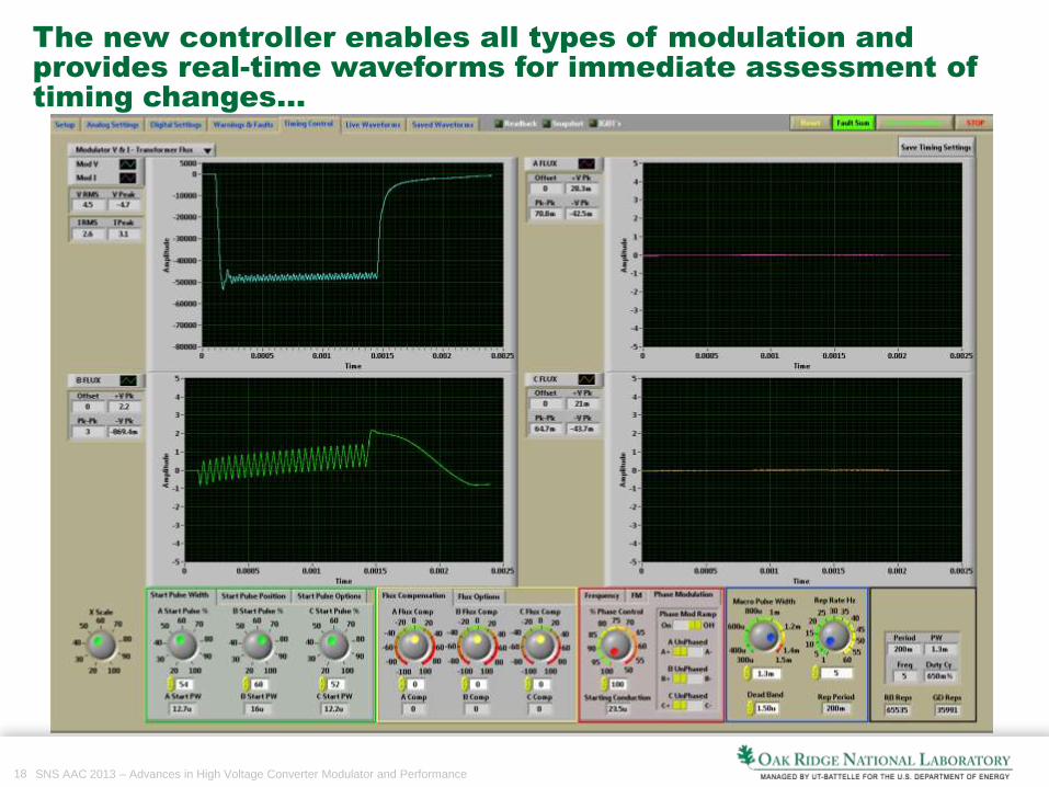
The new controller enables all types of modulation and
provides real-time waveforms for immediate assessment of
timing changes…
19 SNS AAC 2013 – Advances in High Voltage Converter Modulator and Performance
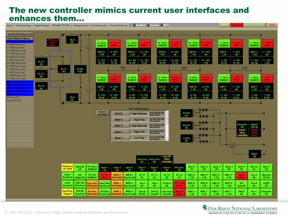
The new controller mimics current user interfaces and
enhances them…
20 SNS AAC 2013 – Advances in High Voltage Converter Modulator and Performance
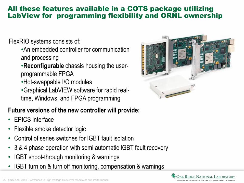
All these features available in a COTS package utilizing
LabView for programming flexibility and ORNL ownership
FlexRIO systems consists of:
•An embedded controller for communication
and processing
•Reconfigurable chassis housing the user-
programmable FPGA
•Hot-swappable I/O modules
•Graphical LabVIEW software for rapid real-
time, Windows, and FPGA programming
Future versions of the new controller will provide:
• EPICS interface
• Flexible smoke detector logic
• Control of series switches for IGBT fault isolation
• 3 & 4 phase operation with semi automatic IGBT fault recovery
• IGBT shoot-through monitoring & warnings
• IGBT turn on & turn off monitoring, compensation & warnings
21 SNS AAC 2013 – Advances in High Voltage Converter Modulator and Performance
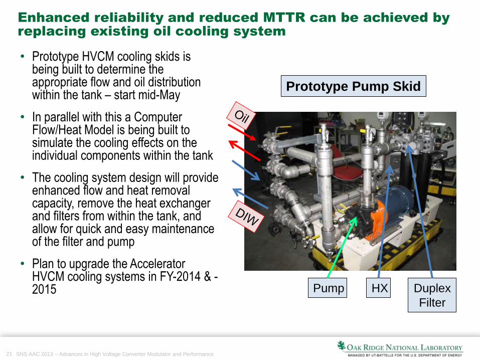
Enhanced reliability and reduced MTTR can be achieved by
replacing existing oil cooling system
• Prototype HVCM cooling skids is being built to determine the appropriate flow and oil distribution within the tank – start mid-May
• In parallel with this a Computer Flow/Heat Model is being built to simulate the cooling effects on the individual components within the tank
• The cooling system design will provide enhanced flow and heat removal capacity, remove the heat exchanger and filters from within the tank, and allow for quick and easy maintenance of the filter and pump
• Plan to upgrade the Accelerator HVCM cooling systems in FY-2014 & -2015
Prototype Pump Skid
Pump Duplex
Filter
HX

22 SNS AAC 2013 – Advances in High Voltage Converter Modulator and Performance
Simulations of temperature profiles and flow rates with
current system reveal system shortcomings
42.7
52.4*
44.2
51.2
53.3*
47.6
36.3
39.9
39
40.684.7
44.8
43.546.6
• Actual measured temperatures at rated power shown in °C in white boxes• Model based on calculated power losses and estimated flow rate only• Temperatures acceptable but oil stagnation indicates heat not being removed efficiently
*diode heat sink temperatures
capxfmr xfmr
diode
diode

23 SNS AAC 2013 – Advances in High Voltage Converter Modulator and Performance
An alternate topology is under investigation for the 2nd
Target
Station with applications to other long pulse facilities
• Single phase waveforms shown• Reduced stress on capacitors• Single phase tested, parts for full
system under procurement• Less sensitive to load variations• Improved soft switching using
magnetizing inductance of transformer• Better efficiency
24 SNS AAC 2013 – Advances in High Voltage Converter Modulator and Performance
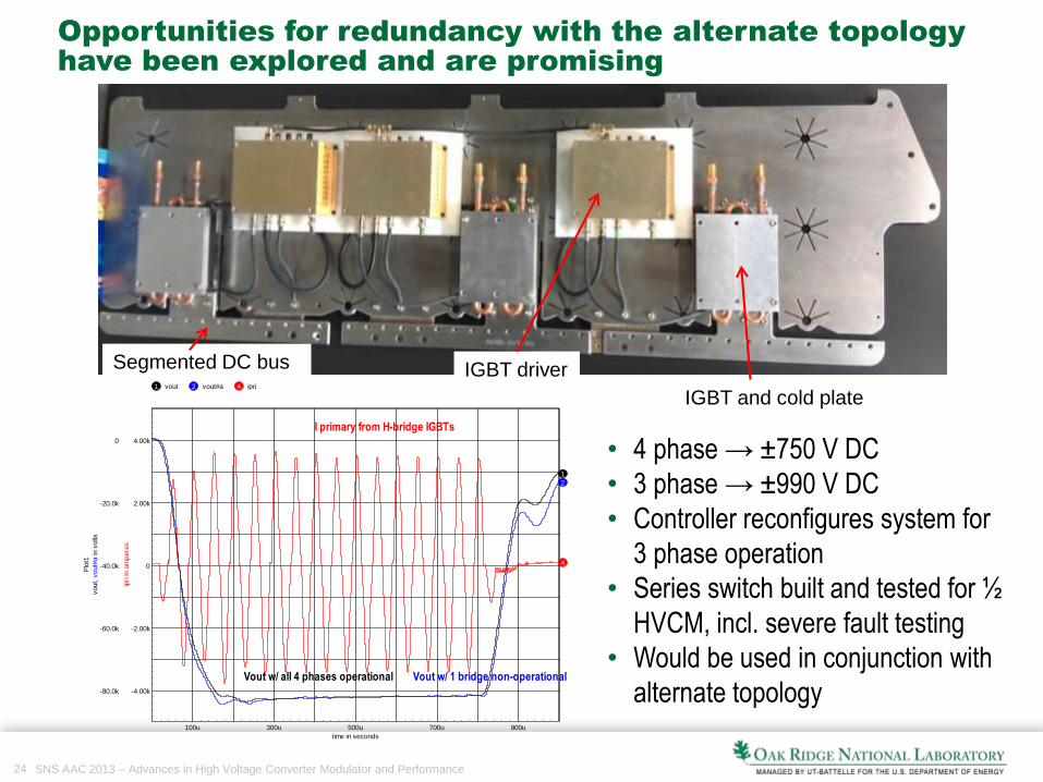
Opportunities for redundancy with the alternate topology
have been explored and are promising
• 4 phase → ±750 V DC
• 3 phase → ±990 V DC
• Controller reconfigures system for
3 phase operation
• Series switch built and tested for ½
HVCM, incl. severe fault testing
• Would be used in conjunction with
alternate topology
1 vout 2 vout#a 4 ipri
100u 300u 500u 700u 900u
time in seconds
-4.00k
-2.00k
0
2.00k
4.00k
ipri in
am
pere
s
-80.0k
-60.0k
-40.0k
-20.0k
0
vout, v
out#
a in
volts
Plo
t1
2
1
4
Vout w/ 1 bridge non-operationalVout w/ all 4 phases operational
I primary from H-bridge IGBTs
IGBT and cold plate
IGBT driverSegmented DC bus
25 SNS AAC 2013 – Advances in High Voltage Converter Modulator and Performance
20KHz @ Start of Pulse & 21.2KHz
@ End
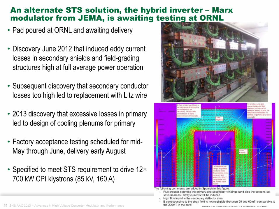
• Pad poured at ORNL and awaiting delivery
• Discovery June 2012 that induced eddy current
losses in secondary shields and field-grading
structures high at full average power operation
• Subsequent discovery that secondary conductor
losses too high led to replacement with Litz wire
• 2013 discovery that excessive losses in primary
led to design of cooling plenums for primary
• Factory acceptance testing scheduled for mid-
May through June, delivery early August
• Specified to meet STS requirement to drive 12×
700 kW CPI klystrons (85 kV, 160 A)
An alternate STS solution, the hybrid inverter – Marx
modulator from JEMA, is awaiting testing at ORNL
26 SNS AAC 2013 – Advances in High Voltage Converter Modulator and Performance
20KHz @ Start of Pulse & 21.2KHz
@ End
• HVCM availability improved substantially
• Synergistic solutions in development or installed to address remaining
problems with HVCM to further improve reliability, increase available
power and flatten pulse
• Capacitor problems continue but multiple options being evaluated
• Implementation of proposed alternate topology allows for future expansion
& major subsystem redundancy
• Supports needs of 2nd Target Station
• Permits more flexibility with respect to load configuration
• The SNS modulator team and the demonstrated HVCM high availability
makes this topology attractive to the ESS, KAERI and others
Summary