Embed Size (px)
Citation preview
Advances in Quenching D. Scott MacKenzie, PhD
Houghton International, Inc. Valley Forge PA, USA
Abstract This paper illustrates the numerous advancements
that have been made in quenching over the past several years, bringing quenching from a black art to an advanced science. A review of the mechanism of quenching, and the causes of distortion and residual stresses will be discussed. In addition, advances in quenching, such as new oil and polymer quenchants, alternative quench methods (gas quenching, induction hardening) will be discussed. New advances in modeling quenchant flow using computational fluid dynamics and modeling distortion, as function of quenchants and heat transfer will also be discussed. Introduction
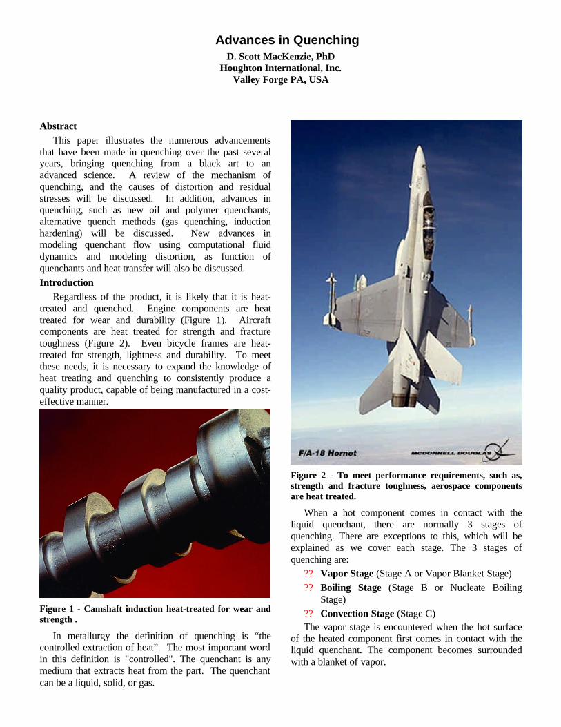
Regardless of the product, it is likely that it is heat-treated and quenched. Engine components are heat treated for wear and durability (Figure 1). Aircraft components are heat treated for strength and fracture toughness (Figure 2). Even bicycle frames are heat-treated for strength, lightness and durability. To meet these needs, it is necessary to expand the knowledge of heat treating and quenching to consistently produce a quality product, capable of being manufactured in a cost-effective manner.
Figure 1 - Camshaft induction heat-treated for wear and strength .
In metallurgy the definition of quenching is “the controlled extraction of heat”. The most important word in this definition is "controlled". The quenchant is any medium that extracts heat from the part. The quenchant can be a liquid, solid, or gas.
Figure 2 - To meet performance requirements, such as, strength and fracture toughness, aerospace components are heat treated.
When a hot component comes in contact with the liquid quenchant, there are normally 3 stages of quenching. There are exceptions to this, which will be explained as we cover each stage. The 3 stages of quenching are:
?? Vapor Stage (Stage A or Vapor Blanket Stage) ?? Boiling Stage (Stage B or Nucleate Boiling
Stage) ?? Convection Stage (Stage C) The vapor stage is encountered when the hot surface
of the heated component first comes in contact with the liquid quenchant. The component becomes surrounded with a blanket of vapor.
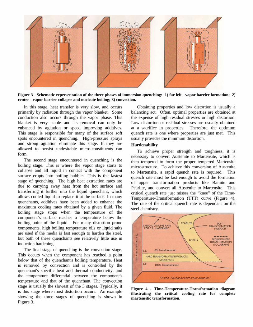
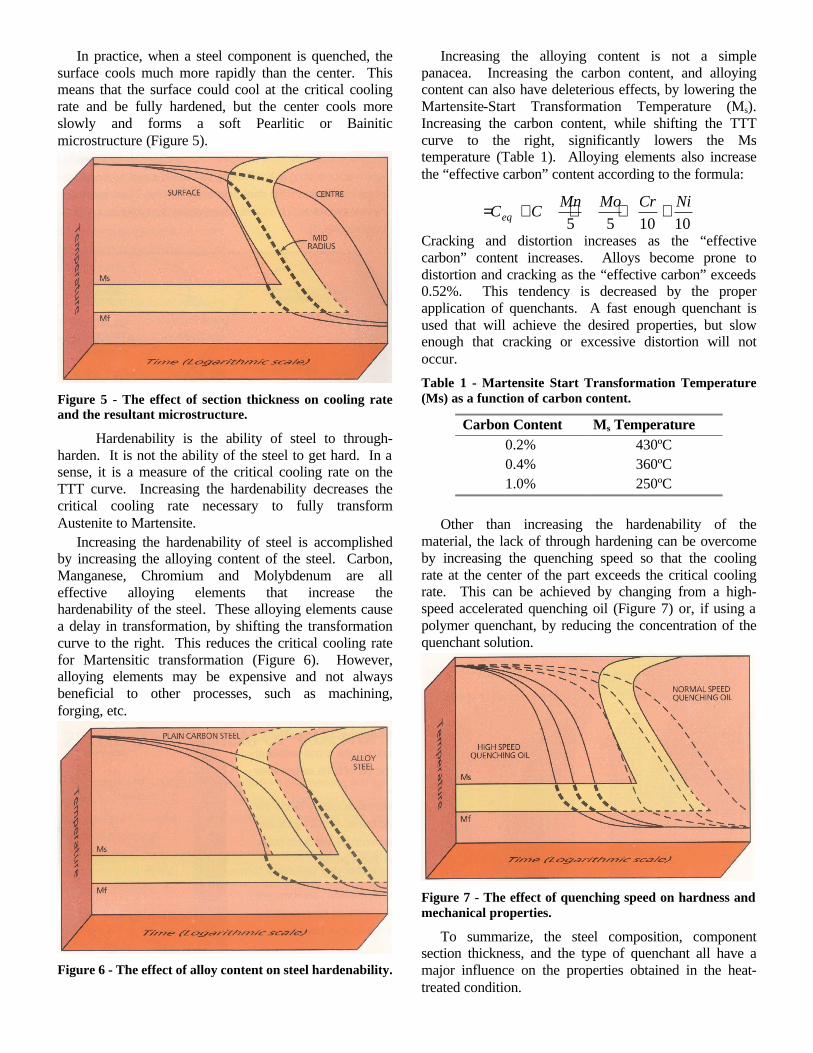
Figure 3 - Schematic representation of the three phases of immersion quenching: 1) far left - vapor barrier formation; 2) center - vapor barrier collapse and nucleate boiling; 3) convection.
In this stage, heat transfer is very slow, and occurs primarily by radiation through the vapor blanket. Some conduction also occurs through the vapor phase. This blanket is very stable and its removal can only be enhanced by agitation or speed improving additives. This stage is responsible for many of the surface soft spots encountered in quenching. High-pressure sprays and strong agitation eliminate this stage. If they are allowed to persist undesirable micro-constituents can form.
The second stage encountered in quenching is the boiling stage. This is where the vapor stage starts to collapse and all liquid in contact with the component surface erupts into boiling bubbles. This is the fastest stage of quenching. The high heat extraction rates are due to carrying away heat from the hot surface and transferring it further into the liquid quenchant, which allows cooled liquid to replace it at the surface. In many quenchants, additives have been added to enhance the maximum cooling rates obtained by a given fluid. The boiling stage stops when the temperature of the component’s surface reaches a temperature below the boiling point of the liquid. For many distortion prone components, high boiling temperature oils or liquid salts are used if the media is fast enough to harden the steel, but both of these quenchants see relatively little use in induction hardening.
The final stage of quenching is the convection stage. This occurs when the component has reached a point below that of the quenchant's boiling temperature. Heat is removed by convection and is controlled by the quenchant's specific heat and thermal conductivity, and the temperature differential between the component's temperature and that of the quenchant. The convection stage is usually the slowest of the 3 stages. Typically, it is this stage where most distortion occurs. An example showing the three stages of quenching is shown in Figure 3.
Obtaining properties and low distortion is usually a balancing act. Often, optimal properties are obtained at the expense of high residual stresses or high distortion. Low distortion or residual stresses are usually obtained at a sacrifice in properties. Therefore, the optimum quench rate is one where properties are just met. This usually provides the minimum distortion. Hardenability
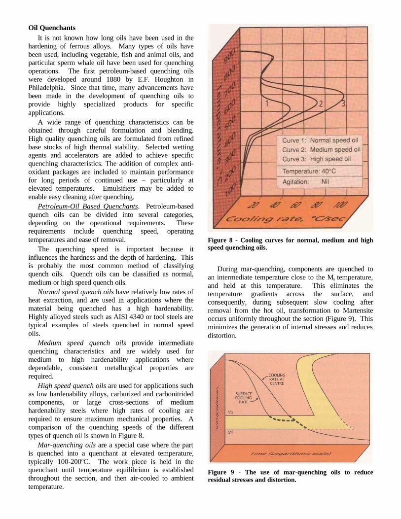
To achieve proper strength and toughness, it is necessary to convert Austenite to Martensite, which is then tempered to form the proper tempered Martensite microstructure. To achieve this conversion of Austenite to Martensite, a rapid quench rate is required. This quench rate must be fast enough to avoid the formation of upper transformation products like Bainite and Pearlite, and convert all Austenite to Martensite. This critical quench rate just misses the “knee” of the Time-Temperature-Transformation (TTT) curve (Figure 4). The rate of the critical quench rate is dependant on the steel chemistry.
Figure 4 - Time-Temperature-Transformation diagram illustrating the critical cooling rate for complete martensitic transformation.
In practice, when a steel component is quenched, the surface cools much more rapidly than the center. This means that the surface could cool at the critical cooling rate and be fully hardened, but the center cools more slowly and forms a soft Pearlitic or Bainitic microstructure (Figure 5).
Figure 5 - The effect of section thickness on cooling rate and the resultant microstructure.
Hardenability is the ability of steel to through-harden. It is not the ability of the steel to get hard. In a sense, it is a measure of the critical cooling rate on the TTT curve. Increasing the hardenability decreases the critical cooling rate necessary to fully transform Austenite to Martensite.
Increasing the hardenability of steel is accomplished by increasing the alloying content of the steel. Carbon, Manganese, Chromium and Molybdenum are all effective alloying elements that increase the hardenability of the steel. These alloying elements cause a delay in transformation, by shifting the transformation curve to the right. This reduces the critical cooling rate for Martensitic transformation (Figure 6). However, alloying elements may be expensive and not always beneficial to other processes, such as machining, forging, etc.
Figure 6 - The effect of alloy content on steel hardenability.
Increasing the alloying content is not a simple panacea. Increasing the carbon content, and alloying content can also have deleterious effects, by lowering the Martensite-Start Transformation Temperature (Ms). Increasing the carbon content, while shifting the TTT curve to the right, significantly lowers the Ms temperature (Table 1). Alloying elements also increase the “effective carbon” content according to the formula:
Cracking and distortion increases as the “effective carbon” content increases. Alloys become prone to distortion and cracking as the “effective carbon” exceeds 0.52%. This tendency is decreased by the proper application of quenchants. A fast enough quenchant is used that will achieve the desired properties, but slow enough that cracking or excessive distortion will not occur.
Table 1 - Martensite Start Transformation Temperature (Ms) as a function of carbon content.
Carbon Content Ms Temperature 0.2% 430ºC 0.4% 360ºC 1.0% 250ºC
Other than increasing the hardenability of the
material, the lack of through hardening can be overcome by increasing the quenching speed so that the cooling rate at the center of the part exceeds the critical cooling rate. This can be achieved by changing from a high-speed accelerated quenching oil (Figure 7) or, if using a polymer quenchant, by reducing the concentration of the quenchant solution.
Figure 7 - The effect of quenching speed on hardness and mechanical properties.
To summarize, the steel composition, component section thickness, and the type of quenchant all have a major influence on the properties obtained in the heat-treated condition.
101055NiCrMoMn
CCeq ++++=
Oil Quenchants It is not known how long oils have been used in the
hardening of ferrous alloys. Many types of oils have been used, including vegetable, fish and animal oils, and particular sperm whale oil have been used for quenching operations. The first petroleum-based quenching oils were developed around 1880 by E.F. Houghton in Philadelphia. Since that time, many advancements have been made in the development of quenching oils to provide highly specialized products for specific applications.
A wide range of quenching characteristics can be obtained through careful formulation and blending. High quality quenching oils are formulated from refined base stocks of high thermal stability. Selected wetting agents and accelerators are added to achieve specific quenching characteristics. The addition of complex anti-oxidant packages are included to maintain performance for long periods of continued use – particularly at elevated temperatures. Emulsifiers may be added to enable easy cleaning after quenching.
Petroleum-Oil Based Quenchants. Petroleum-based quench oils can be divided into several categories, depending on the operational requirements. These requirements include quenching speed, operating temperatures and ease of removal.
The quenching speed is important because it influences the hardness and the depth of hardening. This is probably the most common method of classifying quench oils. Quench oils can be classified as normal, medium or high speed quench oils.
Normal speed quench oils have relatively low rates of heat extraction, and are used in applications where the material being quenched has a high hardenability. Highly alloyed steels such as AISI 4340 or tool steels are typical examples of steels quenched in normal speed oils.
Medium speed quench oils provide intermediate quenching characteristics and are widely used for medium to high hardenability applications where dependable, consistent metallurgical properties are required.
High speed quench oils are used for applications such as low hardenability alloys, carburized and carbonitrided components, or large cross-sections of medium hardenability steels where high rates of cooling are required to ensure maximum mechanical properties. A comparison of the quenching speeds of the different types of quench oil is shown in Figure 8.
Mar-quenching oils are a special case where the part is quenched into a quenchant at elevated temperature, typically 100-200ºC. The work piece is held in the quenchant until temperature equilibrium is established throughout the section, and then air-cooled to ambient temperature.
Figure 8 - Cooling curves for normal, medium and high speed quenching oils.
During mar-quenching, components are quenched to
an intermediate temperature close to the Ms temperature, and held at this temperature. This eliminates the temperature gradients across the surface, and consequently, during subsequent slow cooling after removal from the hot oil, transformation to Martensite occurs uniformly throughout the section (Figure 9). This minimizes the generation of internal stresses and reduces distortion.
Figure 9 - The use of mar-quenching oils to reduce residual stresses and distortion.
Since mar-quenching oils are used at relatively high temperatures, their formulation and physical properties are different from cold quenching oils. They are formulated from very carefully selected base stocks with high oxidation resistance and thermal stability. They have high flash points and viscosities, and contain complex anti-oxidant packages to provide long life. Selection of the mar-quenching oil is based on the operating temperature and quenching characteristics. A minimum of 50ºC should be maintained between the operating temperature of the oil and its flash point. Natural or Vegetable-Based Quenchants.
The most widely used quenchant for ferrous alloys are petroleum-based quenchants due to its favorable heat extraction characteristics. The dependence upon imported oil, price vulnerability, and contamination potential has caused suppliers to investigate alternative sources of quench oil base stock.
There are many reason why vegetable-based oils have seen increased interest. The primary reasons are:
∗ Increased environmental regulation on ground and water contamination;
∗ Need to reduce the reliance on imported petroleum crude oils;
∗ Increased environmental awareness. Canola oil, with its high oleic fat content has been found to offer the best oxidation resistance of any of the common vegetable oils (Soybean, Sunflower seed, Peanut and Palm). Table 1 shows relative advantages to the use of vegetable-based oils for heat-treating.
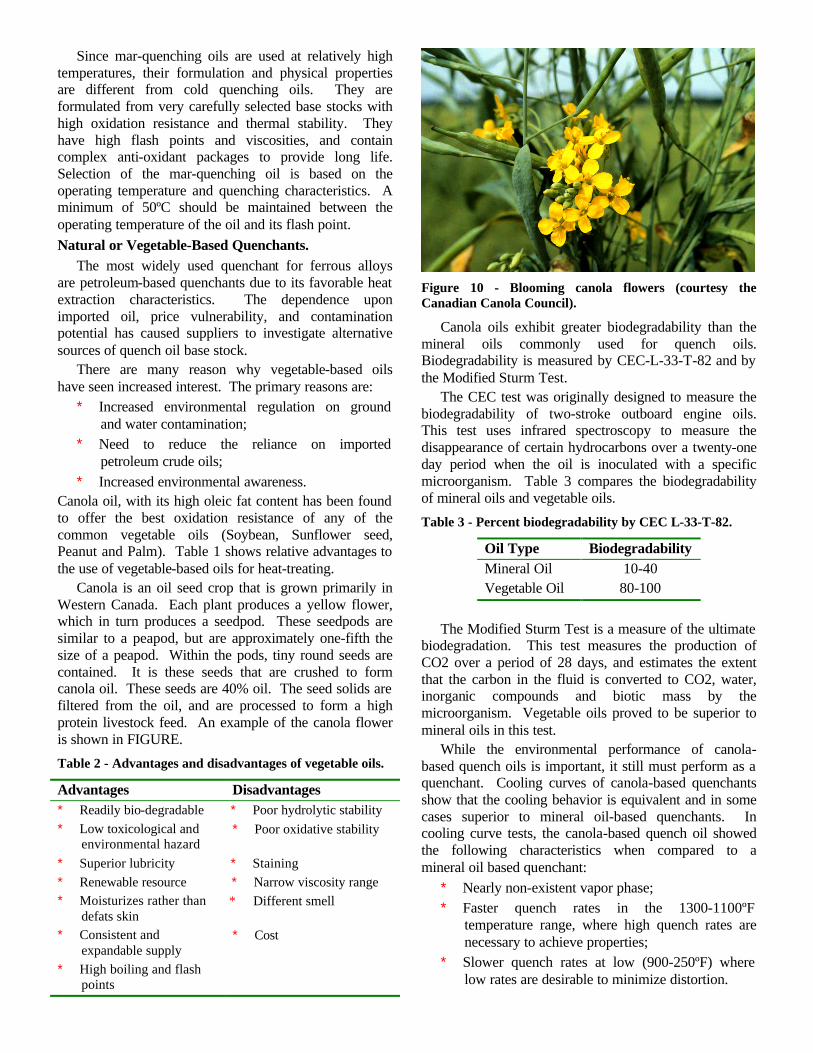
Canola is an oil seed crop that is grown primarily in Western Canada. Each plant produces a yellow flower, which in turn produces a seedpod. These seedpods are similar to a peapod, but are approximately one-fifth the size of a peapod. Within the pods, tiny round seeds are contained. It is these seeds that are crushed to form canola oil. These seeds are 40% oil. The seed solids are filtered from the oil, and are processed to form a high protein livestock feed. An example of the canola flower is shown in FIGURE.
Table 2 - Advantages and disadvantages of vegetable oils.
Advantages Disadvantages ∗ Readily bio-degradable ∗ Poor hydrolytic stability ∗ Low toxicological and
environmental hazard ∗ Poor oxidative stability
∗ Superior lubricity ∗ Staining ∗ Renewable resource ∗ Narrow viscosity range ∗ Moisturizes rather than
defats skin * Different smell
∗ Consistent and expandable supply
∗ Cost
∗ High boiling and flash points
Figure 10 - Blooming canola flowers (courtesy the Canadian Canola Council).
Canola oils exhibit greater biodegradability than the mineral oils commonly used for quench oils. Biodegradability is measured by CEC-L-33-T-82 and by the Modified Sturm Test.
The CEC test was originally designed to measure the biodegradability of two-stroke outboard engine oils. This test uses infrared spectroscopy to measure the disappearance of certain hydrocarbons over a twenty-one day period when the oil is inoculated with a specific microorganism. Table 3 compares the biodegradability of mineral oils and vegetable oils.
Table 3 - Percent biodegradability by CEC L-33-T-82.
Oil Type Biodegradability Mineral Oil 10-40 Vegetable Oil 80-100
The Modified Sturm Test is a measure of the ultimate
biodegradation. This test measures the production of CO2 over a period of 28 days, and estimates the extent that the carbon in the fluid is converted to CO2, water, inorganic compounds and biotic mass by the microorganism. Vegetable oils proved to be superior to mineral oils in this test.
While the environmental performance of canola-based quench oils is important, it still must perform as a quenchant. Cooling curves of canola-based quenchants show that the cooling behavior is equivalent and in some cases superior to mineral oil-based quenchants. In cooling curve tests, the canola-based quench oil showed the following characteristics when compared to a mineral oil based quenchant:
∗ Nearly non-existent vapor phase; ∗ Faster quench rates in the 1300-1100ºF
temperature range, where high quench rates are necessary to achieve properties;
∗ Slower quench rates at low (900-250ºF) where low rates are desirable to minimize distortion.
The high boiling temperature of the canola oil, which is almost 166ºC (300ºF) above the boiling temperature of most petroleum quench oils and the higher flash point of 332ºC (630ºF) for the canola oil versus the petroleum-based quench oil flash temperature of 177-232ºC (350-450ºF) are both beneficial physical characteristics for a quench oil. The higher flash point gives greater safety during quenching, while the higher boiling temperature provides for an increased transition temperature between nucleate boiling and convection. This temperature is very important in reducing the temperature gradients, which result in residual stresses during transformation. The virtual absence of a vapor phase contributes to a uniform heat extraction, and uniform heat transfer across the surface of the part. Polymer Quenchants.
Polymer quenchants consist of solutions of organic polymers in water, and contain organic inhibitors and other additives to produce concentrates, which are further diluted for use. The various types of polymer quenchants have widely differing properties. Great flexibility of quenching characteristics is possible through selection of the type of polymer, polymer concentration, temperature of the quench bath, and the degree of agitation.
The successful application of polymer quenchants depends on many factors, including the hardenability of the steel, section thickness, the type of furnace and quenching system, and the physical properties required. The advantages of polymer quenchants fall into three categories: environmental; technical and production.
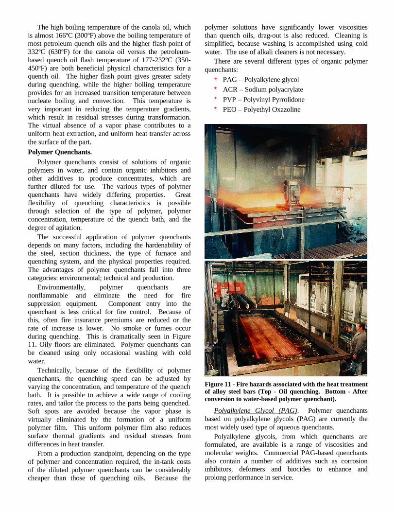
Environmentally, polymer quenchants are nonflammable and eliminate the need for fire suppression equipment. Component entry into the quenchant is less critical for fire control. Because of this, often fire insurance premiums are reduced or the rate of increase is lower. No smoke or fumes occur during quenching. This is dramatically seen in Figure 11. Oily floors are eliminated. Polymer quenchants can be cleaned using only occasional washing with cold water.
Technically, because of the flexibility of polymer quenchants, the quenching speed can be adjusted by varying the concentration, and temperature of the quench bath. It is possible to achieve a wide range of cooling rates, and tailor the process to the parts being quenched. Soft spots are avoided because the vapor phase is virtually eliminated by the formation of a uniform polymer film. This uniform polymer film also reduces surface thermal gradients and residual stresses from differences in heat transfer.
From a production standpoint, depending on the type of polymer and concentration required, the in-tank costs of the diluted polymer quenchants can be considerably cheaper than those of quenching oils. Because the
polymer solutions have significantly lower viscosities than quench oils, drag-out is also reduced. Cleaning is simplified, because washing is accomplished using cold water. The use of alkali cleaners is not necessary.
There are several different types of organic polymer quenchants:
* PAG – Polyalkylene glycol ∗ ACR – Sodium polyacrylate ∗ PVP – Polyvinyl Pyrrolidone ∗ PEO – Polyethyl Oxazoline
Figure 11 - Fire hazards associated with the heat treatment of alloy steel bars (Top - Oil quenching. Bottom - After conversion to water-based polymer quenchant).
Polyalkylene Glycol (PAG). Polymer quenchants based on polyalkylene glycols (PAG) are currently the most widely used type of aqueous quenchants.
Polyalkylene glycols, from which quenchants are formulated, are available is a range of viscosities and molecular weights. Commercial PAG-based quenchants also contain a number of additives such as corrosion inhibitors, defomers and biocides to enhance and prolong performance in service.
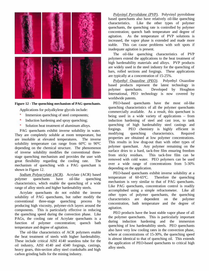
Figure 12 - The quenching mechanism of PAG quenchants.
Applications for polyalkylene glycols include: ∗ Immersion quenching of steel components; ∗ Induction hardening and spray quenching; ∗ Solution heat treatment of aluminum alloys. PAG quenchants exhibit inverse solubility in water.
They are completely soluble at room temperature, but are insoluble at elevated temperatures. The inverse solubility temperature can range from 60ºC to 90ºC depending on the chemical structure. The phenomenon of inverse solubility modifies the conventional three-stage quenching mechanism and provides the user with great flexibility regarding the cooling rate. The mechanism of quenching with a PAG quenchant is shown in Figure 12.
Sodium Polyacrylate (ACR). Acrylate (ACR) based polymer quenchants have oil-like quenching characteristics, which enable the quenching of a wide range of alloy steels and higher hardenability steels.
Acrylate quenchants do not exhibit the inverse solubility of PAG quenchants, but rather modify the conventional three-stage quenching process by producing high viscosity, polymer-rich layers around the components. This is particularly effective in reducing the quenching speed during the convection phase. Like PAGs, the cooling rate of Acrylate quenchants is a function of polymer concentration; quench bath temperature and degree of agitation.
The oil-like characteristics of ACR polymers enable the heat treatment of steels with higher hardenability. These include critical AISI 4140 seamless tube for the oil industry, AISI 4140 and 4340 forgings, castings, heavy gears, thin-section alloy steel crankshafts and high carbon grinding balls for the mining industry.
Polyvinyl Pyrrolidone (PVP). Polyvinyl pyrrolidone based quenchants also have relatively oil-like quenching characteristics. Like the other types of polymer quenchants, the quenching rate is controlled by polymer concentration; quench bath temperature and degree of agitation. As the temperature of PVP solutions is increased, the vapor phase is extended and made more stable. This can cause problems with soft spots if inadequate agitation is present.
The oil-like quenching characteristics of PVP polymers extend the applications to the heat treatment of high hardenability materials and alloys. PVP products are widely used in the steel industry for the quenching of bars, rolled sections and forgings. These applications are typically at a concentration of 15-25%.
Polyethyl Oxazoline (PEO). Polyethyl Oxazoline based products represent the latest technology in polymer quenchants. Developed by Houghton International, PEO technology is now covered by worldwide patents.
PEO-based quenchants have the most oil-like quenching characteristics of all the polymer quenchants commercially available. As a result, this quenchant is being used in a wide variety of applications – from induction hardening of steel and cast iron, to tank quenching of high hardenability steel castings and forgings. PEO chemistry is highly efficient in modifying quenching characteristics. Required properties are obtained at low polymer concentrations. This results in low drag-out than with other types of polymer quenchant. Any polymer remaining on the surface dries to a hard, tack-free film ensuring freedom from sticky residues. This tack-free film can be removed with cold water. PEO polymers can be used over a wide range of concentrations from 5-30% depending on the application.
PEO-based quenchants exhibit inverse solubility at a temperature of 60-65ºC. Therefore the quenching mechanism is very similar to that of PAG quenchants. Like PAG quenchants, concentration control is readily accomplished using a simple refractometer. Like all other types of polymer quenchants, the quenching characteristics are dependent on the polymer concentration, bath temperature and the degree of agitation.
PEO products have the least stable vapor phase of all the polymer quenchants. This is particularly important during induction hardening and the immersion quenching of low hardenability steels. PEO quenchants also have very low cooling rates in the convection phase, where at concentrations of 15-30%, the quenching speed is almost identical to that of quenching oil. This extends the application of PEO-based quenchants to critical high alloy steels.
Alternative Quenching Methods Several methods have been developed to overcome
some of the problems of oil quenching. Each of the primary methods strive to be environmentally friendly, while at the same time achieve improved performance. Two notable methods are “Intensive Quenching” and “Gas Pressure Quenching”
Intensive Quenching. This method was developed by N.I. Kobasko [1]. In practice, this method involves unusually high agitation rates to completely defeat both the vapor and nucleate boiling heat transfer regimes.
Since the 1920s, there have been various quenching practices that have been designated as intensive, drastic, severe, or shell hardening Kern [2] cited an example of intensive quenching a AISI 1035 carbon-steel Model T using a solution of 5% aqueous caustic soda. Other examples include a Rolls Royce P-51 engine crankshaft using highly agitated oil.
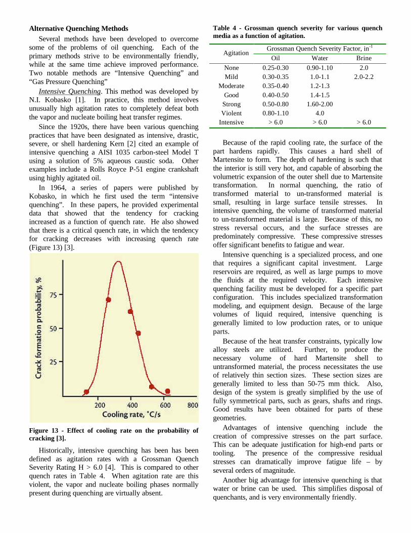
In 1964, a series of papers were published by Kobasko, in which he first used the term “intensive quenching”. In these papers, he provided experimental data that showed that the tendency for cracking increased as a function of quench rate. He also showed that there is a critical quench rate, in which the tendency for cracking decreases with increasing quench rate (Figure 13) [3].
Figure 13 - Effect of cooling rate on the probability of cracking [3].
Historically, intensive quenching has been has been defined as agitation rates with a Grossman Quench Severity Rating H > 6.0 [4]. This is compared to other quench rates in Table 4. When agitation rate are this violent, the vapor and nucleate boiling phases normally present during quenching are virtually absent.
Table 4 - Grossman quench severity for various quench media as a function of agitation.
Grossman Quench Severity Factor, in-1 Agitation
Oil Water Brine None 0.25-0.30 0.90-1.10 2.0 Mild 0.30-0.35 1.0-1.1 2.0-2.2
Moderate 0.35-0.40 1.2-1.3 Good 0.40-0.50 1.4-1.5
Strong 0.50-0.80 1.60-2.00 Violent 0.80-1.10 4.0
Intensive > 6.0 > 6.0 > 6.0
Because of the rapid cooling rate, the surface of the
part hardens rapidly. This causes a hard shell of Martensite to form. The depth of hardening is such that the interior is still very hot, and capable of absorbing the volumetric expansion of the outer shell due to Martensite transformation. In normal quenching, the ratio of transformed material to un-transformed material is small, resulting in large surface tensile stresses. In intensive quenching, the volume of transformed material to un-transformed material is large. Because of this, no stress reversal occurs, and the surface stresses are predominately compressive. These compressive stresses offer significant benefits to fatigue and wear.
Intensive quenching is a specialized process, and one that requires a significant capital investment. Large reservoirs are required, as well as large pumps to move the fluids at the required velocity. Each intensive quenching facility must be developed for a specific part configuration. This includes specialized transformation modeling, and equipment design. Because of the large volumes of liquid required, intensive quenching is generally limited to low production rates, or to unique parts.
Because of the heat transfer constraints, typically low alloy steels are utilized. Further, to produce the necessary volume of hard Martensite shell to untransformed material, the process necessitates the use of relatively thin section sizes. These section sizes are generally limited to less than 50-75 mm thick. Also, design of the system is greatly simplified by the use of fully symmetrical parts, such as gears, shafts and rings. Good results have been obtained for parts of these geometries.
Advantages of intensive quenching include the creation of compressive stresses on the part surface. This can be adequate justification for high-end parts or tooling. The presence of the compressive residual stresses can dramatically improve fatigue life – by several orders of magnitude.
Another big advantage for intensive quenching is that water or brine can be used. This simplifies disposal of quenchants, and is very environmentally friendly.
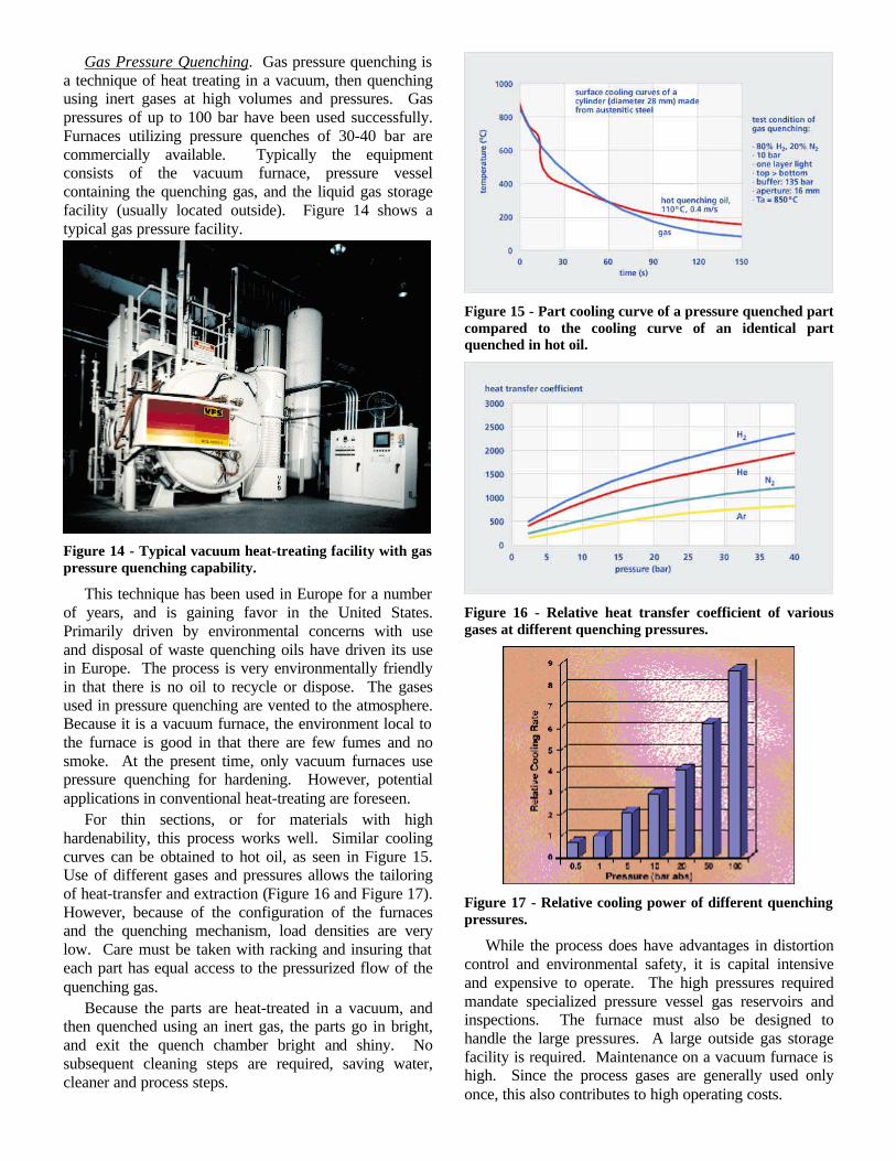
Gas Pressure Quenching. Gas pressure quenching is a technique of heat treating in a vacuum, then quenching using inert gases at high volumes and pressures. Gas pressures of up to 100 bar have been used successfully. Furnaces utilizing pressure quenches of 30-40 bar are commercially available. Typically the equipment consists of the vacuum furnace, pressure vessel containing the quenching gas, and the liquid gas storage facility (usually located outside). Figure 14 shows a typical gas pressure facility.
Figure 14 - Typical vacuum heat-treating facility with gas pressure quenching capability.
This technique has been used in Europe for a number of years, and is gaining favor in the United States. Primarily driven by environmental concerns with use and disposal of waste quenching oils have driven its use in Europe. The process is very environmentally friendly in that there is no oil to recycle or dispose. The gases used in pressure quenching are vented to the atmosphere. Because it is a vacuum furnace, the environment local to the furnace is good in that there are few fumes and no smoke. At the present time, only vacuum furnaces use pressure quenching for hardening. However, potential applications in conventional heat-treating are foreseen.
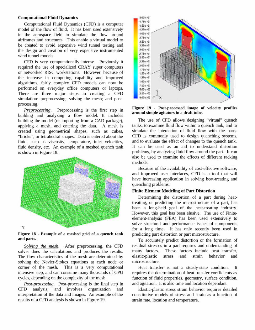
For thin sections, or for materials with high hardenability, this process works well. Similar cooling curves can be obtained to hot oil, as seen in Figure 15. Use of different gases and pressures allows the tailoring of heat-transfer and extraction (Figure 16 and Figure 17). However, because of the configuration of the furnaces and the quenching mechanism, load densities are very low. Care must be taken with racking and insuring that each part has equal access to the pressurized flow of the quenching gas.
Because the parts are heat-treated in a vacuum, and then quenched using an inert gas, the parts go in bright, and exit the quench chamber bright and shiny. No subsequent cleaning steps are required, saving water, cleaner and process steps.
Figure 15 - Part cooling curve of a pressure quenched part compared to the cooling curve of an identical part quenched in hot oil.
Figure 16 - Relative heat transfer coefficient of various gases at different quenching pressures.
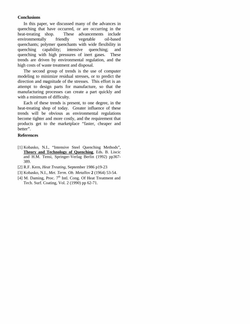
Figure 17 - Relative cooling power of different quenching pressures.
While the process does have advantages in distortion control and environmental safety, it is capital intensive and expensive to operate. The high pressures required mandate specialized pressure vessel gas reservoirs and inspections. The furnace must also be designed to handle the large pressures. A large outside gas storage facility is required. Maintenance on a vacuum furnace is high. Since the process gases are generally used only once, this also contributes to high operating costs.
Computational Fluid Dynamics Computational Fluid Dynamics (CFD) is a computer
model of the flow of fluid. It has been used extensively in the aerospace field to simulate the flow around airframes and structures. This enable a virtual model to be created to avoid expensive wind tunnel testing and the design and creation of very expensive instrumented wind tunnel models.
CFD is very computationally intense. Previously it required the use of specialized CRAY super computers or networked RISC workstations. However, because of the increase in computing capability and improved algorithms, fairly complex CFD models can now be performed on everyday office computers or laptops. There are three major steps in creating a CFD simulation: preprocessing; solving the mesh; and post-processing.
Preprocessing. Preprocessing is the first step in building and analyzing a flow model. It includes building the model (or importing from a CAD package), applying a mesh, and entering the data. A mesh is created using geometrical shapes, such as cubes, “bricks”, or tetrahedral shapes. Data is entered about the fluid, such as viscosity, temperature, inlet velocities, fluid density, etc. An example of a meshed quench tank is shown in Figure 18.
Figure 18 - Example of a meshed grid of a quench tank and parts.
Solving the mesh. After preprocessing, the CFD solver does the calculations and produces the results. The flow characteristics of the mesh are determined by solving the Navier-Stokes equations at each node or corner of the mesh. This is a very computational intensive step, and can consume many thousands of CPU cycles, depending on the complexity of the mesh.
Post-processing. Post-processing is the final step in CFD analysis, and involves organization and interpretation of the data and images. An example of the results of a CFD analysis is shown in Figure 19.
Figure 19 - Post-processed image of velocity profiles around simple agitators in a draft tube.
The use of CFD allows designing “virtual” quench tanks, to examine fluid flow within a quench tank, and to simulate the interaction of fluid flow with the parts. CFD is commonly used to design quenching systems, and to evaluate the effect of changes to the quench tank. It can be used as an aid to understand distortion problems, by analyzing fluid flow around the part. It can also be used to examine the effects of different racking methods.
Because of the availability of cost-effective software, and improved user interfaces, CFD is a tool that will have increasing application in solving heat-treating and quenching problems. Finite Element Modeling of Part Distortion
Determining the distortion of a part during heat-treating, or predicting the microstructure of a part, has been a long-held goal of the heat-treating industry. However, this goal has been elusive. The use of Finite-element-analysis (FEA) has been used extensively to solve structural and performance issues of components for a long time. It has only recently been used in predicting part distortion or part microstructure.
To accurately predict distortion or the formation of residual stresses in a part requires and understanding of many factors. These factors include heat transfer, elastic-plastic stress and strain behavior and microstructure.
Heat transfer is not a steady-state condition. It requires the determination of heat-transfer coefficients as function of fluid properties, geometry, surface condition, and agitation. It is also time and location dependant
Elastic-plastic stress strain behavior requires detailed constitutive models of stress and strain as a function of strain rate, location and temperature.
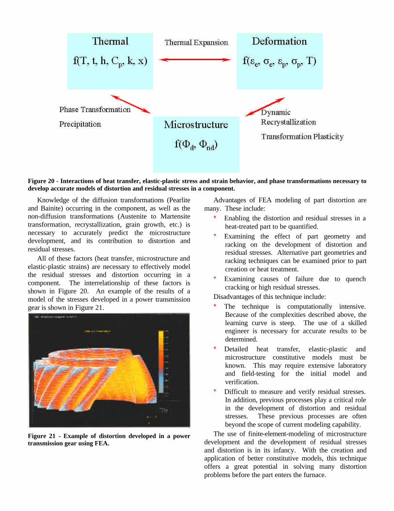
Figure 20 - Interactions of heat transfer, elastic-plastic stress and strain behavior, and phase transformations necessary to develop accurate models of distortion and residual stresses in a component.
Knowledge of the diffusion transformations (Pearlite and Bainite) occurring in the component, as well as the non-diffusion transformations (Austenite to Martensite transformation, recrystallization, grain growth, etc.) is necessary to accurately predict the microstructure development, and its contribution to distortion and residual stresses.
All of these factors (heat transfer, microstructure and elastic-plastic strains) are necessary to effectively model the residual stresses and distortion occurring in a component. The interrelationship of these factors is shown in Figure 20. An example of the results of a model of the stresses developed in a power transmission gear is shown in Figure 21.
Figure 21 - Example of distortion developed in a power transmission gear using FEA.
Advantages of FEA modeling of part distortion are many. These include:
∗ Enabling the distortion and residual stresses in a heat-treated part to be quantified.
∗ Examining the effect of part geometry and racking on the development of distortion and residual stresses. Alternative part geometries and racking techniques can be examined prior to part creation or heat treatment.
∗ Examining causes of failure due to quench cracking or high residual stresses.
Disadvantages of this technique include: ∗ The technique is computationally intensive.
Because of the complexities described above, the learning curve is steep. The use of a skilled engineer is necessary for accurate results to be determined.
∗ Detailed heat transfer, elastic-plastic and microstructure constitutive models must be known. This may require extensive laboratory and field-testing for the initial model and verification.
∗ Difficult to measure and verify residual stresses. In addition, previous processes play a critical role in the development of distortion and residual stresses. These previous processes are often beyond the scope of current modeling capability.
The use of finite-element-modeling of microstructure development and the development of residual stresses and distortion is in its infancy. With the creation and application of better constitutive models, this technique offers a great potential in solving many distortion problems before the part enters the furnace.
Conclusions In this paper, we discussed many of the advances in
quenching that have occurred, or are occurring in the heat-treating shop. These advancements include environmentally friendly vegetable oil-based quenchants; polymer quenchants with wide flexibility in quenching capability; intensive quenching; and quenching with high pressures of inert gases. These trends are driven by environmental regulation, and the high costs of waste treatment and disposal.
The second group of trends is the use of computer modeling to minimize residual stresses, or to predict the direction and magnitude of the stresses. This effort is an attempt to design parts for manufacture, so that the manufacturing processes can create a part quickly and with a minimum of difficulty.
Each of these trends is present, to one degree, in the heat-treating shop of today. Greater influence of these trends will be obvious as environmental regulations become tighter and more costly, and the requirement that products get to the marketplace “faster, cheaper and better”. References [1] Kobasko, N.I., “Intensive Steel Quenching Methods”,
Theory and Technology of Quenching, Eds. B. Liscic and H.M. Tensi, Springer-Verlag Berlin (1992) pp367-389.
[2] R.F. Kern, Heat Treating, September 1986 p19-23 [3] Kobasko, N.I., Met. Term. Ob. Metallov 2 (1964) 53-54. [4] M. Daming, Proc. 7th Intl. Cong. Of Heat Treatment and
Tech. Surf. Coating, Vol. 2 (1990) pp 62-71.