Embed Size (px)
Citation preview
Tribology Intermtional Vol. 30, No. 4, pp. 279-282, 1997 0 1997 Elsevier Science Ltd
Printed in Great Britain. All rights reserved 0301-679X/97/$17.00 +O.OO ELSEVI-:R
SCIENCE’ PII: SO301-679X(96)00056-4
vances in research on a multi- channel on-line ferrograph
Liu Yan*+, Wen ShiZhu*, Xie YouBai* and Zhao Fang*
This paper introduces the basic principle, functions and test resuits of a multi-channel on-line ferrograph. The instrument catches wear debris with an eletitromagnet, detects wear debris with a photoelectric sensor, and controls sampling and data processing with an 8098 single-chip microprocessor which can communicate with a master computer. The instrument has four sampling channels, which can monitor not only one machine but also four machines one by one. The software of the instrument includes five modules which are a main program, a keyboard control program, a floating point operation program, a serial communication program and a self-checking program. The results of experiments on a gear box show that increasing average values detected by the instrument correspond to increasing load, so the instrument can meet the need for on-line monitoring of the wear condition of machines. 0 1997 Elsevier Science Ltd. All rights reserved
Keywords: on-line ferrograph, monitoring, wear, sampling
Introduction
The multi-channel on-line ferrograph is a kind of wear mon:toring instrument with multi-channels, which cat&es wear debris in the oil circulation system of machines with an electromagnet, detects wear debris with photoelectric sensors, and controls sampling and data processing with a microprocessor. The instrument is developed from the OLF-1 on-line ferrograph’ .
The instrument has four sampling channels, which can monitor not only one machine but also four machines one by one. It can be used in oil refineries, steelworks, power stations and ships etc. for monitoring the wear statt. of large machines such as large blowers, large gear boxes and large diesel engines etc.
*N&onal Tribology Laboratory of TsingHuu Universi~, Beijing lOOC84, P.R. China jCotresponding author: Liu I’m, Theor?, of Lubrication and Bearing Institute, Xi ‘an Jiaotong lIniversit)i, Xi ‘an, Shuartxi 710049, P.R. Chinn E-nwil: tlbi@?jtu.deu.cn .jrTheoty of Lubrication and Bearing Institute, Xi‘nn Jiaotong Univer- sity, Xi’an, Shaanxi 710049, P.R. China Paper received 19 July 1995; revised 14 Februaq 1996; accepted 30 July 1996
Its installation and operation are very simple. Two oil pipes are used to connect the instrument and the machines monitored, one of which is for oil input and the other for output. After some initial parameters are input from the keyboard, the instrument runs automati- cally and sampling data will be kept in the instrument which will not be lost even though the power is shut off. The results can be output by a printer or an RS232 serial I/O interface. The wear state of the machines monitored can be identified through a mathematical model program. In addition, the instrument can be combined with any vibration condition monitoring sys- tem to establish a comprehensive on-line failure diag- nosis system.
Together with the analytical ferrograph or the other off-line instruments, people can make up a monitoring system of two levels, on-line monitoring and off-line monitoring. When a fault warning is given in the early stage by the multi-channel on-line ferrograph, further sampling can be made and brought to the laboratory for more precise analysis and diagnosis by the analytical ferrograph or other means. In the two level monitoring system, much work, money and time can be saved and an enhanced monitoring reliability can be ensured. One channel of the multi-channel on-line ferrograph can replace a DR ferrograph also.
Tribology International Volume 30 Number 4 1997 279
Multi-channel on-line ferrograph: Liu Yan et a/.
1
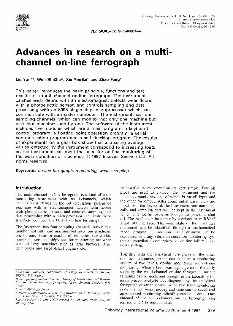
1. Electromagnetic valve 2. Machine 3. Oil channels change set 4. Sampling pump 5. Detector 6. Data acquisition and control system
Fig. I Structure of the multi-channel on-line ferro- graph
Structure and principle
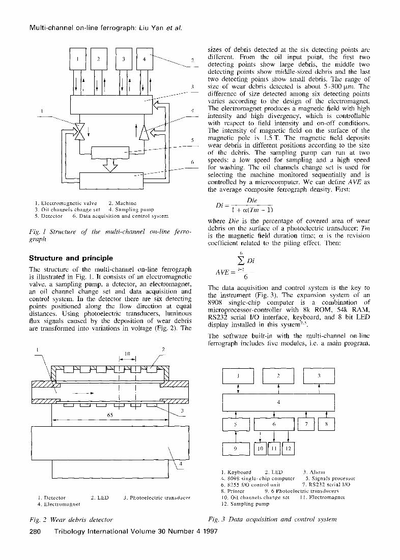
The structure of the multi-channel on-line ferrograph is illustrated in Fig. 1. It consists of an electromagnetic valve, a sampling pump, a detector, an electromagnet, an oil channel change set and data acquisition and control system. In the detector there are six detecting points positioned along the flow direction at equal distances. Using photoelectric transducers, luminous flux signals caused by the deposition of wear debris are transformed into variations in voltage (Fig. 2). The
I \ I I I 1 NJ,,,,
uuq-ly-l
65
1. Detector 2. LED 3. Photoelectric transduce1 4. Electromagnet
Fig. 2 Wear debris detector
sizes of debris detected at the six detecting points are different. From the oil input point, the first two detecting points show large debris, the middle two detecting points show middle-sized debris and the last two detecting points show small debris. The range of size of wear debris detected is about 5-300 pm. The difference of size detected among six detecting points varies according to the design of the electromagnet. The electromagnet produces a magnetic field with high intensity and high divergency, which is controllable with respect to field intensity and on-off conditions. The intensity of magnetic field on the surface of the magnetic pole is 1.5 T. The magnetic field deposits wear debris in different positions according to the size of the debris. The sampling pump can run at two speeds: a low speed for sampling and a high speed for washing. The oil channels change set is used for selecting the machine monitored sequentially and is controlled by a microcomputer. We can define AVE as the average composite ferrograph density. First:
Die Di =
1 + cY(Tm - 1)
where Die is the percentage of covered area of wear debris on the surface of a photoelectric transducer; Tm is the magnetic field duration time; (Y is the revision coefficient related to the piling effect. Then:
i Di AVE = ‘=I
6
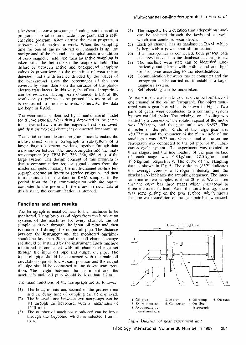
The data acquisition and control system is the key to the instrument (Fig. 3). The expansion system of an 8908 single-chip computer is a combination of microprocessor-controller with Xk ROM, 54k RAM, RS232 serial I/O interface, keyboard, and 8 bit LED display installed in this system2,3.
The software built-in with the multi-channel on-line ferrograph includes five modules, i.e. a main program,
I. Keyboard 2. LED 3. Alarm 4. 8098 single-chip computer 5. Signals processor 6. 8255 I/O control unit 7. RS232 serial I/O 8. Printer 9. 6 Photoelectric transducers 10. Oil channels change set 11. Electromagnet 12. Sampling pump
Fig. 3 Data acquisition and control system
280 Tribology International Volume 30 Number 4 1997
a keyboard control program, a floating point operation program, a serial communication program and a self- checking program. After starting the main program, a software clock begins to work. When the sampling time fo:- one of the monitored oil channels is up, the background of the channel is sampled under a condition of zero magnetic field, and then an active sampling is taken after the build-up of the magnetic field. The difference between active and background sampling values :s proportional to the quantities of wear debris detected, and the difference divided by the values of the background gives the percentages of the area coverec by wear debris on the surfaces of the photo- electric transducers. In this way, the effect of impurities can be reduced. Having been obtained, a list of the results #on six points can be printed if a micro-printer is connected to the instruments. Otherwise, the data are kept in RAM.
The wear state is identified by a mathematical model for triho-diagnosis. Wear debris deposited in the detec- tor is washed away after the magnetic field is removed, and then the next oil channel is connected for sampling.
The serial communication program module makes the multi-channel on-line ferrograph a sub-system of a larger diagnosis system, working together through data transmission between the microcomputer and the mas- ter computer (e.g. IBM-PC, 286, 386, 486, etc.) of the large system. The design concept of this program is that a communication request signal comes from the master computer, making the multi-channel on-line fer- rograph operate an interrupt service program, and then it transmits all of the data in RAM sampled in the period from the last communication with the master computer to the present. If there are no new data at this irstant, the communication is stopped.
ions and test results
The ferrograph is installed near to the machines to be monitored. Using by-pass oil pipes from the lubrication systems of the machines for every channel, the oil sample is drawn through the input oil pipe and then is dramed off through the output oil pipe. The distance between the instrument and the monitored machines should be less than 20 m, and the oil channel change set should be installed by the instrument. Each machine monitored is connected with oil channel change set through the input oil pipe and output oil pipe. The input oil pipe should be connected with the main oil circulation pipe at its upstream position and the output oil pipe should be connected at the downstream pos- ition. The height between the instrument and the machine’s main oil pipe should be less than 1.2 m.
The main functions of the ferrograph are as follows:
(1) The hour, minute and second of the present time and the delay time of sampling can be displayed.
(2) The interval time between two samplings can be set through the keyboard, with a maximums of 1440 min.
(3) The number of machines monitored can be input through the keyboard which is selected from 1 to 4.
Multi-channel on-line ferrograph: Liu Yan et al.
(4) The magnetic field duration time (deposition time) can be selected through the keyboard as well, which can condense wear debris.
(5) Each oil channel has its database in RAM, which is kept with a power shut-off protection.
(6) If a microprinter is connected, both present data and previous data in the database can be printed.
(7) The machine wear state can be identified auto- matically and alarms with both sound and light can be given according to the identification.
(8) Communication between master computer and the ferrograph can be carried out to establish a larger diagnosis system.
(9) Self-checking can be undertaken.
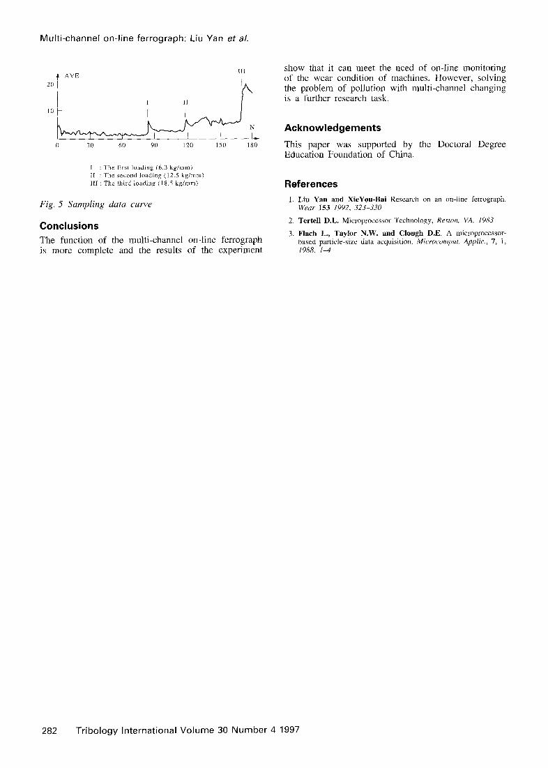
An experiment was made to check the performance of one channel of the on-line ferrograph. The object moni- tored was a gear box which is shown in Fig. 4. Two pairs of gears were conntected to a confining system by two parallel shafts. The twisting force loading was loaded by a connector. The rotation speed of the motor was 1200 rpm, and the gear ratio was 98132. The diameter of the pitch circle of the large gear was 150.77 mm and the diameter of the pitch circle of the small gear was 49.23 mm. One channel of the on-line ferrograph was connected to the oil pipe of the lubri- cation cycle system. The experiment was divided to three stages, and the line loading of the gear surface of each stage was 6.3 kg/mm, 12.5 kg/mm and 18.5 kg/mm, respectively. The curve of the sampling data is shown in Fig. 5. The ordinate (AVE) indicates the average composite ferrograph density and the abscissa (N) indicates the sampling sequence. The inter- val time of two samples is about 20 min. We can see that the curve has three stages which correspond to three increases in load. After the third loading, there was some pitting on the gear surface, which shows that the wear condition of the gear pair had worsened.
Direction of oil flow ---t f-
1. Oil pipe 2. MotoT 3. Oil pump 4. Oil tank 5. Experiment gear 6. Connector 7. On-line 8. Accompanying ferrograph
experiment gear
Fig. 4 Diagram of gear experiment unit
Tribology International Volume 30 Number 4 1997 281
Multi-channel on-line ferrograph: Liu Yan et al.
+ AVE III
I : The first loading 16.3 kg/mm) II : The second loading (12.5 kg/mm) III : The third loading (18.5 kg/mm)
Fig. 5 Sampling data curve
Conclusions
The function of the multi-channel on-line ferrograph is more complete and the results of the experiment
show that it can meet the need of on-line monitoring of the wear condition of machines. However, solving the problem of pollution with multi-channel changing is a further research task.
Acknowledgements
This paper was supported by the Doctoral Degree Education Foundation of China.
References
1. Liu Yan and XieYou-Bai Research on an on-line ferrograph. Wear 153 1992. 323-330
7. Tertell D.L. Microprocessor Technology, Reston, VA, 1983
3. Flach L., Taylor N.W. and Clough D.E. A microprocessor- based particle-size data acquisition. Microcomput. Applic., 7, 1, 1988, 14
282 Tribology International Volume 30 Number 4 1997