Embed Size (px)
Citation preview

Health Checks through Landmark Bridges to Sky-high Structures
by
Y. Q. Ni, K. Y. Wong and Y. Xia
Reprinted from
Advances in Structural EngineeringVolume 14 No. 1 2011
MULTI-SCIENCE PUBLISHING CO. LTD.5 Wates Way, Brentwood, Essex CM15 9TB, United Kingdom
1. INTRODUCTIONLarge-scale structures such as long-span bridges andhigh-rise towers are vital civil infrastructure.Maintaining their safe and reliable operation is criticalin securing the well being of people, protecting the vastinvestments, and supporting the vitality of theeconomy. However, civil engineering structures cannotlast forever; they begin to deteriorate as soon as they arebuilt. As a result, it is of paramount importance todiagnose and prognose the safety of large-scale civilengineering structures throughout their entire life cycle.The significance of implementing long-term SHMsystems to secure structural and operational safety andto issue early warnings on damage or deterioration prior
Health Checks through Landmark Bridges
to Sky-high Structures
Y. Q. Ni1,*, K. Y. Wong2 and Y. Xia1
1Department of Civil and Structural Engineering, The Hong Kong Polytechnic University, Hung Hom, Kowloon, Hong Kong, China2Bridges and Structures Division, Highways Department, The Government of the Hong Kong Special Administrative Region,
Hong Kong, China
Abstract: Massive infrastructure projects developed in Hong Kong make for bigchallenges and unique opportunities for engineers and researchers. The construction ofthe cables-stayed Stonecutters Bridge sets up a new landmark in the bridge engineeringcommunity, with its main span exceeding 1,000 m as well as its sophisticatedinstrumentation system comprising more than 1,500 sensors. The development ofstructural health monitoring (SHM) technology has evolved for over 10 years in HongKong since the implementation of the so-called “Wind And Structural HealthMonitoring System (WASHMS)” on the suspension Tsing Ma Bridge in 1997. Thesuccessful engineering paradigms of implementing and operating SHM systems for fivecable-supported bridges and experiences gained by practice and research in the pastdecade have promoted the applications of this technology beyond Hong Kong andextending from long-span bridges to high-rise structures. In this paper, the evolution inthe design methodology for SHM systems, the advancement in several aspects of SHMtechnology, and a performance comparison between the early implemented and latelydeveloped SHM systems for large-scale bridges are first outlined. Subsequently, theconcept of the so-called “life-cycle structural health monitoring (LSHM)” is addressedby exploring the integration of in-construction monitoring and in-service monitoringand by realizing such an integrated system to a super-tall tower structure. The issue onhow an SHM system benefits structural vibration control is also discussed.
Key words: life-cycle structural health monitoring, long-span bridges, high-rise structures, integration of healthmonitoring and vibration control.
*Corresponding author. Email address: [email protected]; Fax: +852-23346389; Tel: +852-27666004.
Advances in Structural Engineering Vol. 14 No. 1 2011 103
to costly repair or even catastrophic collapse has beenincreasingly recognized (Ko and Ni 2005).
In the past decade, five long-span cable-supportedbridges, namely the Tsing Ma Bridge, the Kap ShuiMun Bridge, the Ting Kau Bridge, the Western CorridorBridge, and the Stonecutters Bridge, have been built inHong Kong. All five bridges have been instrumentedwith a sophisticated on-line SHM system, named “WindAnd Structural Health Monitoring System (WASHMS)”(Wong 2004, 2007). The WASHMS has also beenperiodically updated in order to effectively execute thefunctions of structural condition monitoring under in-service condition and structural degradation evaluationas it occurs. The successful engineering paradigms of
Health Checks through Landmark Bridges to Sky-high Structures
104 Advances in Structural Engineering Vol. 14 No. 1 2011
implementing and operating SHM systems for thesebridges and experiences gained by practice and researchin the past decade have promoted the applications of thistechnology beyond Hong Kong and extending fromlong-span bridges to high-rise structures.
2. SHM SYSTEMS FOR BRIDGES IN HONG KONG
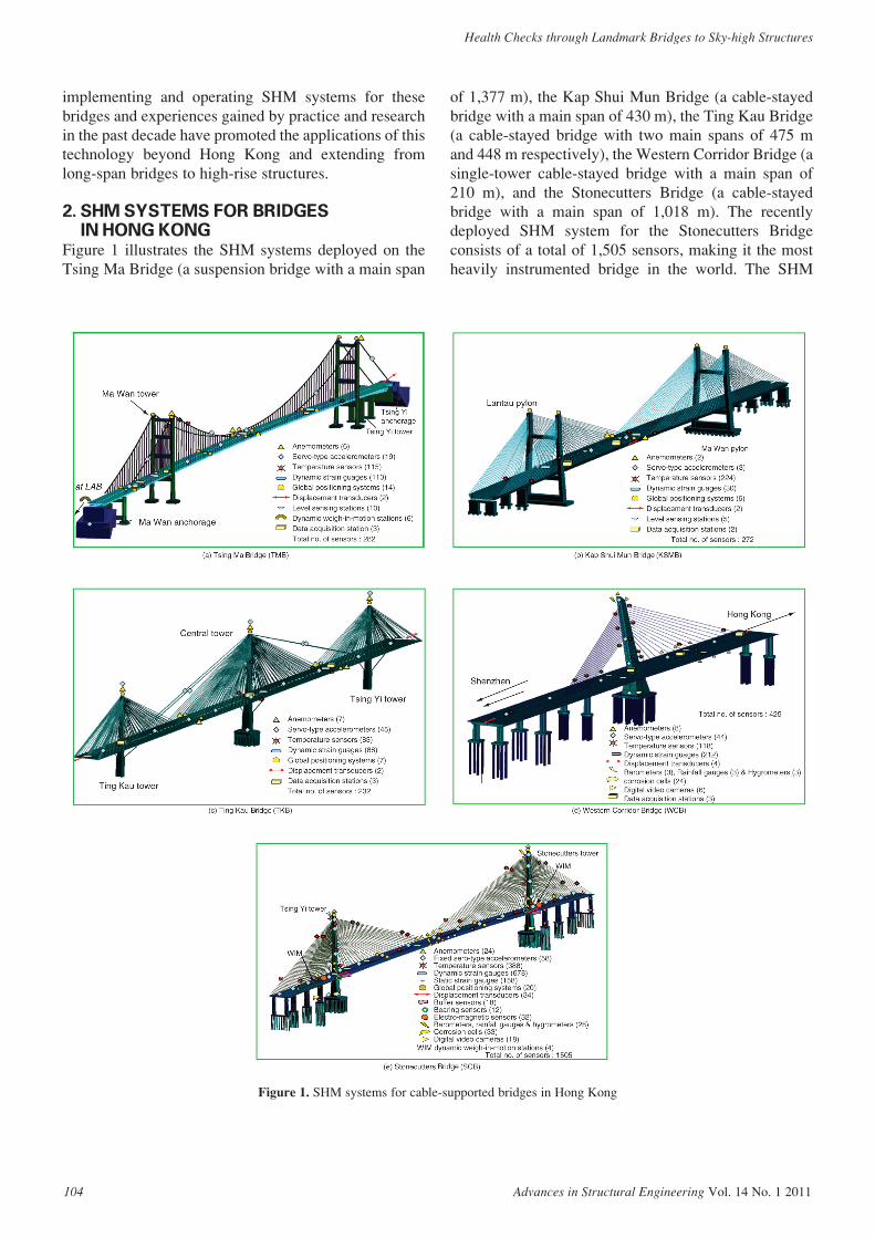
Figure 1 illustrates the SHM systems deployed on theTsing Ma Bridge (a suspension bridge with a main span
of 1,377 m), the Kap Shui Mun Bridge (a cable-stayedbridge with a main span of 430 m), the Ting Kau Bridge(a cable-stayed bridge with two main spans of 475 mand 448 m respectively), the Western Corridor Bridge (asingle-tower cable-stayed bridge with a main span of210 m), and the Stonecutters Bridge (a cable-stayedbridge with a main span of 1,018 m). The recentlydeployed SHM system for the Stonecutters Bridgeconsists of a total of 1,505 sensors, making it the mostheavily instrumented bridge in the world. The SHM
Figure 1. SHM systems for cable-supported bridges in Hong Kong
Y. Q. Ni, K. Y. Wong and Y. Xia
Advances in Structural Engineering Vol. 14 No. 1 2011 105
systems for bridges in Hong Kong were devised for thefollowing purposes:
• To validate design assumptions and parameterswith the potential benefit of improving designspecifications and guidelines for future similarstructures;
• To detect anomalies in loading and response andpossible damage/deterioration at an early stageto ensure structural and operational safety;
• To provide real-time information for health andsafety assessment immediately after disastersand extreme events;
• To provide evidence and instructions forplanning and prioritizing structural inspection,maintenance, rehabilitation, and repair;
• To monitor repairs and reconstruction with theview of evaluating the effectiveness ofmaintenance, retrofit and repair works; and
• To obtain massive amounts of in-situ data forcutting-edge research.
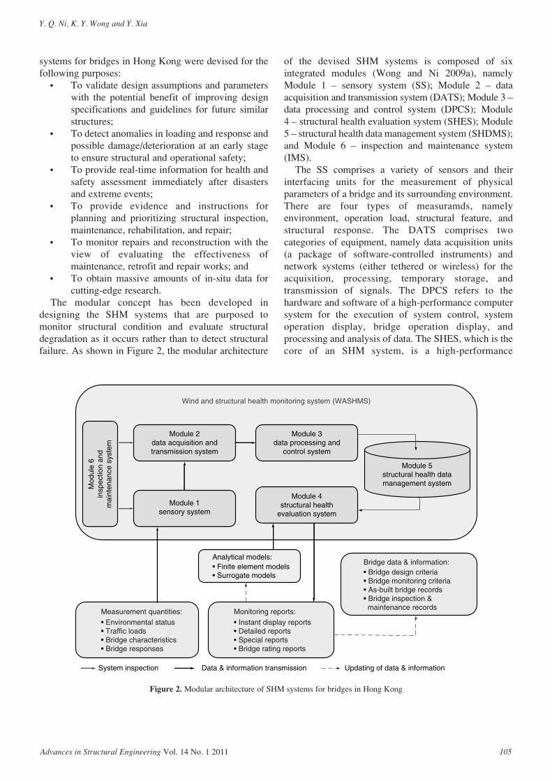
The modular concept has been developed indesigning the SHM systems that are purposed tomonitor structural condition and evaluate structuraldegradation as it occurs rather than to detect structuralfailure. As shown in Figure 2, the modular architecture
of the devised SHM systems is composed of sixintegrated modules (Wong and Ni 2009a), namelyModule 1 – sensory system (SS); Module 2 – dataacquisition and transmission system (DATS); Module 3 –data processing and control system (DPCS); Module 4 – structural health evaluation system (SHES); Module5 – structural health data management system (SHDMS);and Module 6 – inspection and maintenance system(IMS).
The SS comprises a variety of sensors and theirinterfacing units for the measurement of physicalparameters of a bridge and its surrounding environment.There are four types of measuramds, namelyenvironment, operation load, structural feature, andstructural response. The DATS comprises twocategories of equipment, namely data acquisition units(a package of software-controlled instruments) andnetwork systems (either tethered or wireless) for theacquisition, processing, temporary storage, andtransmission of signals. The DPCS refers to thehardware and software of a high-performance computersystem for the execution of system control, systemoperation display, bridge operation display, andprocessing and analysis of data. The SHES, which is thecore of an SHM system, is a high-performance
Wind and structural health monitoring system (WASHMS)
Mod
ule
6in
spec
tion
and
mai
nten
ance
sys
tem
Module 2data acquisition andtransmission system
Module 3data processing and
control system
Module 4structural health
evaluation system
Module 5structural health datamanagement system
Module 1sensory system
Analytical models:
• Environmental status• Traffic loads• Bridge characteristics• Bridge responses
Measurement quantities: Monitoring reports:• Instant display reports• Detailed reports• Special reports• Bridge rating reports
Bridge data & information:• Bridge design criteria• Bridge monitoring criteria• As-built bridge records• Bridge inspection & maintenance records
System inspection Data & information transmission Updating of data & information
• Finite element models• Surrogate models
Figure 2. Modular architecture of SHM systems for bridges in Hong Kong
Health Checks through Landmark Bridges to Sky-high Structures
106 Advances in Structural Engineering Vol. 14 No. 1 2011
computer system equipped with appropriate softwaretools for the execution of inter-solver finite elementanalysis, sensitivity analysis and model updating, bridgefeature and response analysis, diagnostic and prognosticanalysis, and visualization of analyzed results. Itincludes an on-line structural condition evaluationsystem and an off-line structural health and safetyassessment system. The on-line structural conditionevaluation system is mainly to compare the static anddynamic measurement data with the design values,finite element analysis results, and pre-determinedthresholds and patterns to provide a prompt evaluationon the structural condition; while the off-line structuralhealth and safety assessment system incorporates avariety of model-based and data-driven diagnostic andprognostic algorithms which mostly require bothhistorical and current monitoring data. The SHDMS iscomposed of a high-performance computer system, adata repository system, and a data warehousemanagement system for the storage and retrieval ofmonitoring data and analysis results. The IMS is alaptop-computer-aided portable system for theinspection and maintenance of sensors, data acquisitionunits, data transmission networks, and display facilities.
To facilitate the bridge inspection and the bridgemaintenance prioritization, three operational strategieshave been defined for each of the SHM systems (Wongand Ni 2009b). Operation Strategy I is normal structuralcondition monitoring. It refers to the measurementvalues of the physical quantities (σMeasured) which areless than 75% of the designated monitoring values(σSLS). Here the designated values σSLS are the bridgedesign loads and responses at the serviceability limitstate. Under such a condition, only routine statisticalanalysis and reports of measurement results are required.Operation Strategy II is critical structural conditionmonitoring. It refers to the values of σMeasured which arein between 75% and 100% of those of σSLS. Under sucha condition, the structural evaluation of measurementresults from finite element and/or surrogate models arerequired to check any over-displaced or over-stressedphenomenon occurring in non-instrumented or keylocations/components. If so, inform the bridgemaintenance team to carry out a detailed inspection onproblematic locations/components. Operation StrategyIII is structural degradation evaluation. It refers to thevalues of σMeasured which are equal to or greater than100% of those of σSLS. Under such a condition, thedetailed the structural evaluation based on measurementdata and analytical results from finite element and/orsurrogate models are required to check any damageinduced and assess the adverse effects of such damage onglobal bridge performance. If so, inform the bridge
maintenance team to carry out a detailed inspection andassess the scope and time of remedial action, wherenecessary.
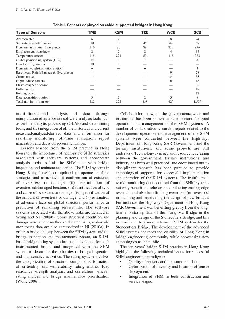
3. EXPERIENCES AND LESSONS LEARNEDTable 1 lists the type and number of sensors installed onthe five bridges in Hong Kong. The SHM system for theTsing Ma Bridge (TMB) was implemented in 1997when the bridge construction was completed, while theSHM system for the Stonecutters Bridge (SCB) has justcompleted its implementation. A comparison betweenthese two systems can be made: (i) the sensors for TMBwere mainly deployed on the half span in Ma Wan sidein consideration of symmetry, whereas the sensors forSCB were distributed along the entire span; (ii) theanemometers for TMB were deployed only for verticalcorrelation, while the anemometers for SCB weredeployed for both vertical and horizontal correlations;(iii) the SHM for TMB excludes durability monitoring,whereas the SHM system for SCB includes corrosionsensors, rainfall gauges, barometers, hygrometers tomonitor durability; and (iv) the SHM for TMBoriginally adopted a file-based data managementsystem, while the SHM system for SCB uses a datarepository system together with a data warehousesystem. The experience gained in the past decadeindicates that durability may govern the condition andhealth of a sea-crossing bridge over its service life cycle;and therefore durability monitoring has currentlybecome an important part of SHM systems for sea-crossing bridges, especially for those located in northChina regions with heavy freezing-thawing cycling andsevere saline concentration (Shao et al. 2010).
The SHM for TMB originally adopted a file-baseddata management system, which has the limitations of(i) separation and isolation of data – difficult to accessfiles for data processing and impossible forsynchronizing processing of more than two data-files,(ii) duplication of data – loss of data integrity orconsistence, (iii) data dependence – creation of one-offprograms, (iv) incompatible file formats – difficult forjoint processing of multiple data-files, and (v) fixedqueries or proliferation of application programs. Suchlimitations result in two major drawbacks: (i) longduration of operation for data retrieval, processing andanalysis, and (ii) very difficult or even impossible tocarry out three or more dimensional correlation andregression analysis. In order to overcome suchlimitations, a data repository system and a datawarehouse system have been introduced in the updatedSHDMS to realize: (i) standardization andnormalization of data, (ii) semi-automatic operation ofretrieval, processing and analysis of measured data, (iii)
Y. Q. Ni, K. Y. Wong and Y. Xia
Advances in Structural Engineering Vol. 14 No. 1 2011 107
multi-dimensional analysis of data throughmanipulation of appropriate software analysis tools suchas on-line analytic processing (OLAP) and data miningtools, and (iv) integration of all the historical and currentmeasured/analyzed/derived data and information forreal-time monitoring, off-time evaluation, reportgeneration and decision recommendation.
Lessons learned from the SHM practice in HongKong tell the importance of appropriate SHM strategiesassociated with software systems and appropriateanalysis tools to link the SHM data with bridgeinspection and maintenance action. The SHM systems inHong Kong have been updated to operate in threestrategies and to achieve (i) confirmation of existence of overstress or damage, (ii) determination ofoverstressed/damaged location, (iii) identification of typeand cause of overstress or damage, (iv) quantification ofthe amount of overstress or damage, and (v) estimationof adverse effects on global structural performance orprediction of remaining service life. The softwaresystems associated with the above tasks are detailed inWong and Ni (2009b). Some structural condition anddamage assessment methods validated using real-worldmonitoring data are also summarized in Ni (2010a). Inorder to bridge the gap between the SHM system and thebridge inspection and maintenance system, an SHM-based bridge rating system has been developed for eachinstrumented bridge and integrated with the SHMsystem to determine the priorities of bridge inspectionand maintenance activities. The rating system involvesthe categorization of structural components, formationof criticality and vulnerability rating matrix, loadresistance strength analysis, and correlation betweenrating indices and bridge maintenance prioritization(Wong 2006).
Collaboration between the government/owner andinstitutions has been shown to be important for goodoperation and management of the SHM systems. Anumber of collaborative research projects related to thedevelopment, operation and management of the SHMsystems were conducted between the HighwaysDepartment of Hong Kong SAR Government and thetertiary institutions, and some projects are stillunderway. Technology synergy and resource leveragingbetween the government, tertiary institutions, andindustry has been well practiced, and coordinated multi-disciplinary research has been pursued to providetechnological supports for successful implementationand operation of the SHM systems. The fruitful real-world monitoring data acquired from the SHM systemsnot only benefit the scholars in conducting cutting-edgeresearch, and also benefit the government (or investors)in planning and supervising the design of new bridges.For instance, the Highways Department of Hong KongSAR Government was benefiting greatly from the long-term monitoring data of the Tsing Ma Bridge in theplanning and design of the Stonecutters Bridge, and thisin turn came to a more advanced SHM system for theStonecutters Bridge. The development of the advancedSHM systems enhances the visibility of Hong Kong inbridge engineering community while showcasing newtechnologies to the public.
The ten years’ bridge SHM practice in Hong Konghighlights the following technical issues for successfulSHM engineering paradigms:
• Quality of sensors and measurement data;• Optimization of intensity and location of sensor
deployment;• Integration of SHM in both construction and
service stages;
Table 1. Sensors deployed on cable-supported bridges in Hong Kong
Type of Sensors TMB KSM TKB WCB SCB
Anemometer 6 2 7 8 24Servo-type accelerometer 19 3 45 44 58Dynamic and static strain gauge 110 30 88 212 836Displacement transducer 2 2 2 4 34Temperature sensor 115 224 83 118 388Global positioning system (GPS) 14 6 7 — 20Level sensing station 10 5 — — —Dynamic weigh-in-motion station 6 — 6 — 4Barometer, Rainfall gauge & Hygrometer — — — 9 28Corrosion cell — — — 24 33Digital video camera — — — 6 18Elasto-magnetic sensor — — — — 32Buffer sensor — — — — 18Bearing sensor — — — — 12Data acquisition station 3 2 2 3 8Total number of sensors 282 272 238 425 1,505
Health Checks through Landmark Bridges to Sky-high Structures
108 Advances in Structural Engineering Vol. 14 No. 1 2011
• Integration of SHM system with bridgeinspection, maintenance and management; and
• Maintenance and management of SHM systemitself.
Optimal sensor placement (OSP) is an importantissue in practicing SHM. While a number of theoreticalinvestigations on this topic have been made, the existentOSP methods are not practical for instructing theoptimal placement of dense sensors of different types ona large-scale bridge. The research envisaged in thefollowing may direct OSP methods to be moreapplicable: (i) performance-based OPS by taking intoaccount both structural information aspect andcommunication/networking constraints (e.g., analogsignal transmission deterioration), (ii) simultaneousoptimization of sensor placement and data acquisitionstation placement, and (iii) multi-scale or multi-objective optimization inclusive of both static-typesensors and dynamic-type sensors.
4. EXTENSION OF SHM PRACTICE FROMBRIDGES TO SKYSCRAPERS
The bridge SHM practice and experiences gained in thepast decade have been extended to develop long-termSHM systems for high-rise structures. The SHM systemfor the Guangzhou New TV Tower (GNTVT) is such anexample. Being the landmark of the Guangzhou city inChina, the GNTVT is a supertall tube-in-tube structurewith a total height of 610 m. The main tower of 454 mhigh is composed of a reinforced concrete innerstructure with an ellipse cross-section of 14 m × 17 mand a steel lattice outer structure with its cross-sectionbeing a varying oval which decreases from 50 m × 80 mat the ground to the minimum of 20.65 m × 27.5 m at theheight of 280 m (waist level), and then increases to 41 m × 55 m at the top of the main tower. There are 37 floors connecting the inner and outer structures.The antenna mast of 156 m high, founded on the top ofthe main tower, is a steel spatial structure with anoctagonal cross-section of 14 m in the maximumdiagonal. The GNTVT serves for multiple functions ofTV and radio transmission, sightseeing, culturalentertainment, and accommodating an orbital Ferriswheel, a ceremony hall, observatory decks, 4D cinemas,revolving restaurants, skywalk, etc. The structuralconstruction of GNTVT was completed in May 2009.
To ensure safety and serviceability of this landmarkstructure during and after its construction, asophisticated long-term SHM system has been designedand implemented by The Hong Kong PolytechnicUniversity in collaboration with Sun Yat-Sen Universityfor real-time monitoring of GNTVT at both in-construction and in-service stages (Ni et al. 2009b). In
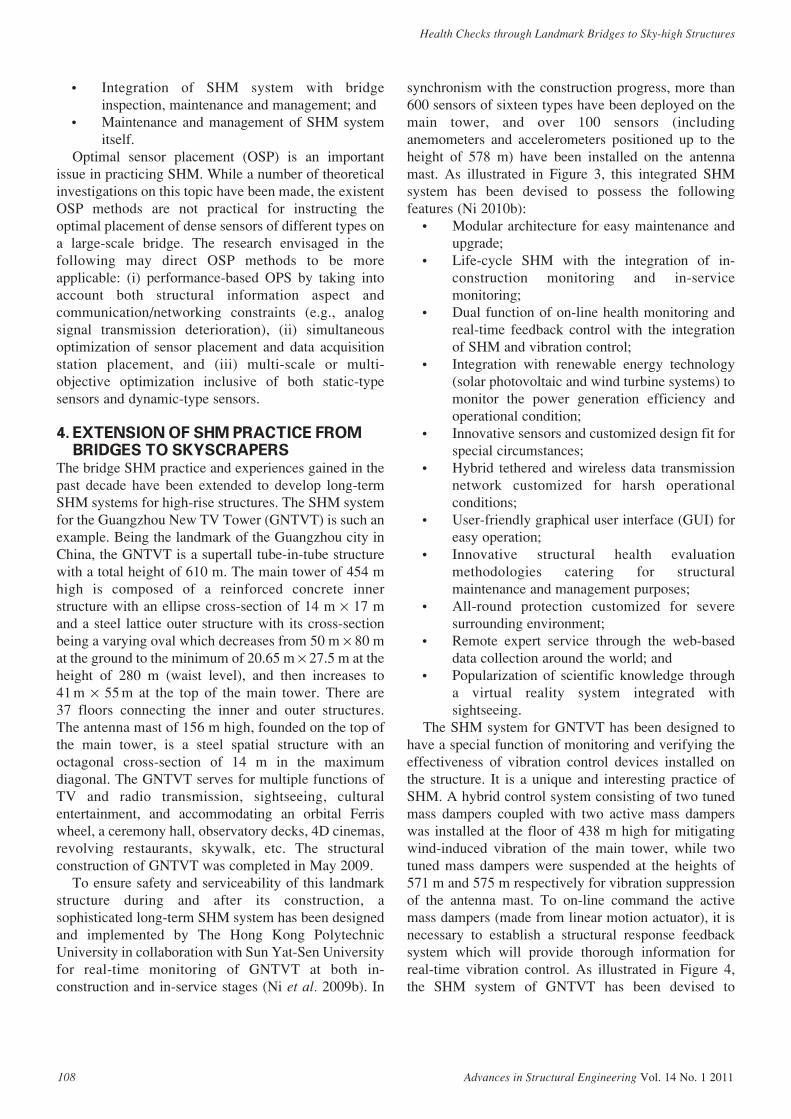
synchronism with the construction progress, more than600 sensors of sixteen types have been deployed on themain tower, and over 100 sensors (includinganemometers and accelerometers positioned up to theheight of 578 m) have been installed on the antennamast. As illustrated in Figure 3, this integrated SHMsystem has been devised to possess the followingfeatures (Ni 2010b):
• Modular architecture for easy maintenance andupgrade;
• Life-cycle SHM with the integration of in-construction monitoring and in-servicemonitoring;
• Dual function of on-line health monitoring andreal-time feedback control with the integrationof SHM and vibration control;
• Integration with renewable energy technology(solar photovoltaic and wind turbine systems) tomonitor the power generation efficiency andoperational condition;
• Innovative sensors and customized design fit forspecial circumstances;
• Hybrid tethered and wireless data transmissionnetwork customized for harsh operationalconditions;
• User-friendly graphical user interface (GUI) foreasy operation;
• Innovative structural health evaluationmethodologies catering for structuralmaintenance and management purposes;
• All-round protection customized for severesurrounding environment;
• Remote expert service through the web-baseddata collection around the world; and
• Popularization of scientific knowledge througha virtual reality system integrated withsightseeing.
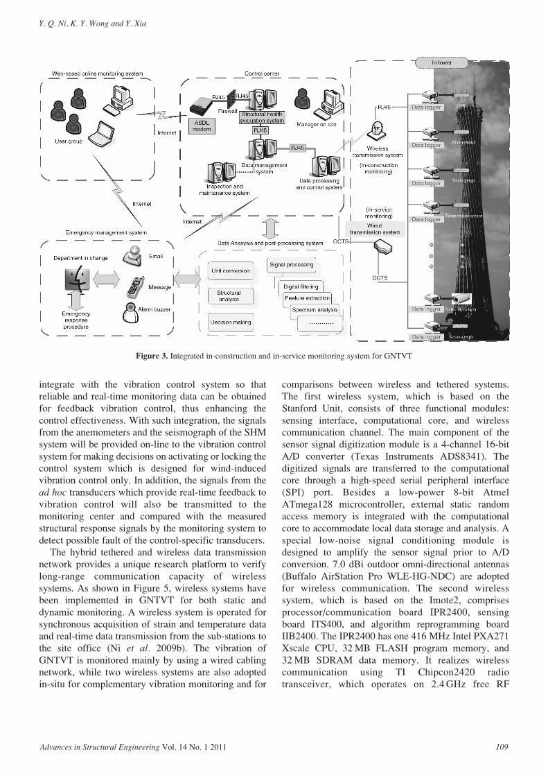
The SHM system for GNTVT has been designed tohave a special function of monitoring and verifying theeffectiveness of vibration control devices installed onthe structure. It is a unique and interesting practice ofSHM. A hybrid control system consisting of two tunedmass dampers coupled with two active mass damperswas installed at the floor of 438 m high for mitigatingwind-induced vibration of the main tower, while twotuned mass dampers were suspended at the heights of571 m and 575 m respectively for vibration suppressionof the antenna mast. To on-line command the activemass dampers (made from linear motion actuator), it isnecessary to establish a structural response feedbacksystem which will provide thorough information forreal-time vibration control. As illustrated in Figure 4,the SHM system of GNTVT has been devised to
Y. Q. Ni, K. Y. Wong and Y. Xia
Advances in Structural Engineering Vol. 14 No. 1 2011 109
integrate with the vibration control system so thatreliable and real-time monitoring data can be obtainedfor feedback vibration control, thus enhancing thecontrol effectiveness. With such integration, the signalsfrom the anemometers and the seismograph of the SHMsystem will be provided on-line to the vibration controlsystem for making decisions on activating or locking thecontrol system which is designed for wind-inducedvibration control only. In addition, the signals from thead hoc transducers which provide real-time feedback tovibration control will also be transmitted to themonitoring center and compared with the measuredstructural response signals by the monitoring system todetect possible fault of the control-specific transducers.
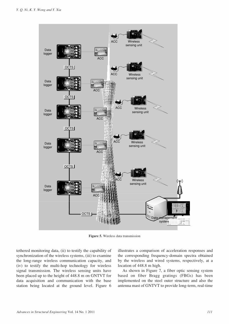
The hybrid tethered and wireless data transmissionnetwork provides a unique research platform to verifylong-range communication capacity of wirelesssystems. As shown in Figure 5, wireless systems havebeen implemented in GNTVT for both static anddynamic monitoring. A wireless system is operated forsynchronous acquisition of strain and temperature dataand real-time data transmission from the sub-stations tothe site office (Ni et al. 2009b). The vibration ofGNTVT is monitored mainly by using a wired cablingnetwork, while two wireless systems are also adoptedin-situ for complementary vibration monitoring and for
comparisons between wireless and tethered systems.The first wireless system, which is based on theStanford Unit, consists of three functional modules:sensing interface, computational core, and wirelesscommunication channel. The main component of thesensor signal digitization module is a 4-channel 16-bitA/D converter (Texas Instruments ADS8341). Thedigitized signals are transferred to the computationalcore through a high-speed serial peripheral interface(SPI) port. Besides a low-power 8-bit AtmelATmega128 microcontroller, external static randomaccess memory is integrated with the computationalcore to accommodate local data storage and analysis. Aspecial low-noise signal conditioning module isdesigned to amplify the sensor signal prior to A/Dconversion. 7.0 dBi outdoor omni-directional antennas(Buffalo AirStation Pro WLE-HG-NDC) are adoptedfor wireless communication. The second wirelesssystem, which is based on the Imote2, comprisesprocessor/communication board IPR2400, sensingboard ITS400, and algorithm reprogramming boardIIB2400. The IPR2400 has one 416 MHz Intel PXA271Xscale CPU, 32 MB FLASH program memory, and 32 MB SDRAM data memory. It realizes wirelesscommunication using TI Chipcon2420 radiotransceiver, which operates on 2.4 GHz free RF
Figure 3. Integrated in-construction and in-service monitoring system for GNTVT
Health Checks through Landmark Bridges to Sky-high Structures
110 Advances in Structural Engineering Vol. 14 No. 1 2011
spectrum and has a communication bandwidth up to 250 Kbps. The software platform based on TinyOS isopen-source, and customized data analysis algorithmscan be reprogrammed into the IPR2400. Taking the
tethered system as a reference, the above two wirelesssensing systems are currently tested in the field with thepurposes: (i) to verify the systems’ reliability andmeasurement precision by comparing the wireless and
ACC ACC DIS DIS DIS DIS
ACC
ACC
ACC
VEL
VEL
ACC
VEL
ACC
VEL
Structural health monitoring system
ACC
ACC ACC
ACCACC
DAU7
DAU5
DAU4
OCTSVibration control system
DAU3
DAU2
DAU1
OCTS
DAU6
DAU8
Seismograph
Anemometer
Bus coupler
Figure 4. Integration of SHM and vibration control
Y. Q. Ni, K. Y. Wong and Y. Xia
Advances in Structural Engineering Vol. 14 No. 1 2011 111
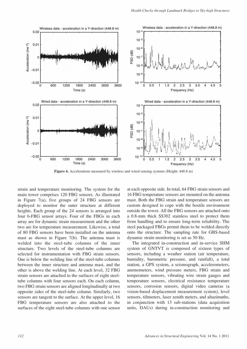
tethered monitoring data, (ii) to testify the capability ofsynchronization of the wireless systems, (iii) to examinethe long-range wireless communication capacity, and(iv) to testify the multi-hop technology for wirelesssignal transmission. The wireless sensing units havebeen placed up to the height of 448.8 m on GNTVT fordata acquisition and communication with the basestation being located at the ground level. Figure 6
illustrates a comparison of acceleration responses andthe corresponding frequency-domain spectra obtainedby the wireless and wired systems, respectively, at alocation of 448.8 m high.
As shown in Figure 7, a fiber optic sensing systembased on fiber Bragg gratings (FBGs) has beenimplemented on the steel outer structure and also theantenna mast of GNTVT to provide long-term, real-time
Figure 5. Wireless data transmission
Datalogger
OCTS
OCTS
OCTS
Data managementsystem
OCTS
OCTS
Datalogger
Datalogger
Datalogger
Datalogger
ACC
ACC
ACC
ACC
ACC
ACC
ACC
Wirelesssensing unit
Wirelesssensing unit
Wirelesssensing unit
Wirelesssensing unit
Wirelesssensing unit
ACC
ACC
ACC
Health Checks through Landmark Bridges to Sky-high Structures
112 Advances in Structural Engineering Vol. 14 No. 1 2011
strain and temperature monitoring. The system for themain tower comprises 120 FBG sensors. As illustratedin Figure 7(a), five groups of 24 FBG sensors aredeployed to monitor the outer structure at differentheights. Each group of the 24 sensors is arranged intofour 6-FBG sensor arrays. Four of the FBGs in eacharray are for dynamic strain measurement and the othertwo are for temperature measurement. Likewise, a totalof 80 FBG sensors have been installed on the antennamast as shown in Figure 7(b). The antenna mast iswelded into the steel-tube columns of the innerstructure. Two levels of the steel-tube columns areselected for instrumentation with FBG strain sensors.One is below the welding line of the steel-tube columnsbetween the inner structure and antenna mast, and theother is above the welding line. At each level, 32 FBGstrain sensors are attached to the surfaces of eight steel-tube columns with four sensors each. On each column,two FBG strain sensors are aligned longitudinally at twoopposite sides of the steel-tube column. Similarly, twosensors are tangent to the surface. At the upper level, 16FBG temperature sensors are also attached to thesurfaces of the eight steel-tube columns with one sensor
at each opposite side. In total, 64 FBG strain sensors and16 FBG temperature sensors are mounted on the antennamast. Both the FBG strain and temperature sensors arecustom designed to cope with the hostile environmentoutside the tower. All the FBG sensors are attached ontoa 0.8-mm thick SS302 stainless steel to protect themfrom handling and to ensure long-term reliability. Thesteel packaged FBGs permit them to be welded directlyonto the structure. The sampling rate for GBS-baseddynamic strain monitoring is set as 50 Hz.
The integrated in-construction and in-service SHMsystem of GNTVT is composed of sixteen types ofsensors, including a weather station (air temperature,humidity, barometric pressure, and rainfall), a totalstation, a GPS system, a seismograph, accelerometers,anemometers, wind pressure meters, FBG strain andtemperature sensors, vibrating wire strain gauges andtemperature sensors, electrical resistance temperaturesensors, corrosion sensors, digital video cameras (avision-based displacement measurement system), levelsensors, tiltmeters, laser zenith meters, and altazimuths,in conjunction with 13 sub-stations (data acquisitionunits, DAUs) during in-construction monitoring and
Wireless data - acceleration in a Y-direction (448.8 m)
Wired data - acceleration in a Y-direction (448.8 m) Wired data - acceleration in a Y-direction (448.8 m)
Wireless data - acceleration in a Y-direction (448.8 m)0.02
0.01
0
0
−0.01
−0.020 600 1200 1800 2400 3000 3600
Time (s)
Acc
eler
atio
n (m
s−2 )
0.02
0.01
−0.01
−0.020 600 1200 1800 2400 3000 3600
Time (s)
Acc
eler
atio
n (m
s−2 )
10−4
10−5
10−6
10−7
10−8
10−9
10−10
PS
D (
dB)
10−4
10−5
10−6
10−7
10−8
10−9
10−10
PS
D (
dB)
0 0.5 1 1.5 2 532.5 3.5 4.54Frequency (Hz)
0 0.5 1 1.5 2 532.5 3.5 4.54Frequency (Hz)
Figure 6. Accelerations measured by wireless and wired sensing systems (Height: 448.8 m)

Y. Q. Ni, K. Y. Wong and Y. Xia
Advances in Structural Engineering Vol. 14 No. 1 2011 113
FBG Interrogator
Channel 1
Channel 2 Channel 3
Channel 4
ComputerLAN
1 × 4Coupler
1×4coupler
1 × 2 Coupler
80%20%
1 × 2 Coupler
80%20%
1 × 2 Coupler
80%20%
1 × 2 Coupler
80%20%
1 × 4Coupler
1 × 4Coupler
1 × 4Coupler
Measured 20:80 split ratios1 × 2 Coupler is very flat from1510 nm to 1590 nm.-Everstar TM
Sensors : Ch1-B-s# and Ch1-B-t#s1 = 1510 nms2 = 1513 nms3 = 1516 nms4 = 1519 nmt1 = 1522 nmt2 = 1524 nm
Sensors : Ch2-B-s# and Ch2-B-t#s1 = 1526 nms2 = 1529 nms3 = 1532 nms4 = 1535 nmt1 = 1538 nmt2 = 1540 nm
Max. link loss (return) < 20 dBDynamic range needed ~ 5 dB
(a) Main tower
Figure 7. (Continued)

Health Checks through Landmark Bridges to Sky-high Structures
114 Advances in Structural Engineering Vol. 14 No. 1 2011
Coupler1 × 2
Coupler1 × 2
1 × 2Coupler
1 × 2Coupler
1 × 2Coupler
1 × 2Coupler
1 × 2Coupler
1 × 2Coupler
Pillar 7
Pillar 8
Pillar 1
Pillar 2
Pillar 6
Pillar 5
Pillar 4
Pillar 3
HS2VS1
VS3
VS5
VS7
(b) Antenna mast
T1
T2HS4
HS6
HS8
Figure 7. FBG sensors for dynamic strain and temperature monitoring

Y. Q. Ni, K. Y. Wong and Y. Xia
Advances in Structural Engineering Vol. 14 No. 1 2011 115
5 DAUs during in-service monitoring. As a result, thisproject offers a unique engineering paradigm to exploresensor and information fusion for SHM. It is difficult tocalibrate or verify the dynamic displacementmeasurement results by a GPS system, and such acalibration or verification is usually conducted in anindirect way by doubly integrating the measuredacceleration data. However, this approach cannotprovide an accurate reference of dynamic displacementbecause of unknown initial displacement and numericalerror. In this project, a vision-based system has beendeveloped and used together with a GPS system fordynamic displacement measurement of GNTVT. Thisvision-based system is capable of remote long-distance(500 to 1,000 m) dynamic displacement measurementwith a sampling frequency between 5 and 60 Hz.Figure 8 shows a comparison of dynamic displacementresponses at the top of the main tower (454 m high)measured by the vision-based system and the GPSsystem. It is observed that while the displacementresponses measured by the two systems coincide wellwith each other, the displacement obtained by thevision-based system is less noise-corrupted and does notexhibit spikes.
The SHM strategy for GNTVT has been defined inthree levels: (i) on-line structural condition evaluation;(ii) target-oriented verification and evaluation; and (iii)off-line structural health and safety assessment. The on-line structural condition evaluation is mainly tocompare the static and dynamic measurement data with the pre-determined thresholds and patterns toprovide a prompt evaluation on the structural condition. The target-oriented verification and evaluation refers to monitoring-based verification/evaluation oftemperature-induced deformation and thermal stress,fatigue life of welded steel connections, wind loadingand wind effects below and above the gradient windlevel, human comfortability during typhoons, etc. The
off-line structural health and safety assessment involvea variety of model-based and data-driven damagediagnostic and prognostic algorithms includingdynamic-based methods, static-based methods, andhybrid methods (Ni et al. 2009b).
As the data acquisition system is operated toautomatically and continuously acquire monitoring data,the SHM system has detected the extreme responses ofGNTVT during the Wenchuan earthquake as well as theNeroguri typhoon, Kammuri typhoon, Nuri typhoon,Hagupit typhoon, Molave typhoon, and Koppu typhoonin the past two years (Ni et al. 2009a). Figure 9illustrates the recorded strain responses of GNTVTduring the Wenchuan earthquake and the Nerogurityphoon. Based on these monitoring data, structuralcondition and health evaluation has been made forGNTVT after each of the events and the evaluationreports have been submitted to the owner of GNTVT.The city of Guangzhou is located at the edge of the mostactive typhoon generating area in the world. As themaximum gradient wind level stipulated in the currentChinese design code is 450 m high, the wind-resistantdesign parameters obtained from the specificationusually fail to provide an accurate description of thefluctuating wind loads acting on supertall structureshigher than 450 m. Because anemometer andaccelerometers have been deployed on GNTVT up to578 m high, we are able to investigate the windproperties and wind effects above the maximumgradient wind level by using the monitoring data ofwind and structural response acquired during typhoons.It will contribute to the development of new designcodes for super-tall buildings and structures.
The SHM system for GNTVT is a long-termmonitoring system. Some of the sensors and sensingcables are located outside. To ensure a long-term stablesystem operation, all-round protection is required for allthe sensors, sensing cables, and data acquisition and
Vision GPS
10:48:00
150.00
100.00
50.00
12:00:00 13:12:00 14:24:00 15:36:00 16:48:00
0.00
−50.00
−100.00
Displacement measurement for vision inspection system vs GPS
Dis
plac
emen
t (m
m)
Figure 8. Comparison of dynamic displacement measured by GPS and vision-based system

Health Checks through Landmark Bridges to Sky-high Structures
116 Advances in Structural Engineering Vol. 14 No. 1 2011
transmission systems (Figure 10). To escape from theproblems of paint-off and weak weld strength, all of thepre-embedded pieces were welded on the steel membersprior to installing the sensors and sensing cables on tothe outer structure. Detachable stainless steel cases andwire ducts were utilized to protect the sensors andsensing cables, whilst aluminum alloy protection caseswere adopted for the fiber optic sensors. Specific sealantwas used to seal up the apertures. All of these adoptedmeasures not only made the sensor system presentablein its outlook, but also made it waterproof anddustproof. Pre-protection measures for embeddedsensors are necessary prior to the sensor installation to
avoid damage to the sensors (e.g., vibration wire straingauges which were embedded into the inner structure).Sensing cables to the sub-stations were safeguarded byzinc plating steel tubes. The sub-stations were protectedby special industrial mainframe-boxes to ensurelightning protection, moisture-proof, electro-magnetic-interference prevention and temperature control. Thealuminum alloy wire ducts were adopted to protect the sensing cables between the control center and the sub-stations.
The GNTVT, designed with the function ofsightseeing and cultural entertainment, is deemed to bean ideal and unique place for tourist sightseeing and at
0 1 2 3 4 5 6 7 8 9 101112131415161718192021222324−167
−166
−165
−164
−163
−162
−161
−160
−159
−158
−157
Str
ain
(µε)
(b) During Neroguri typhoon
Time (hour)
13:00−189
−188
−187
−186
−185
−184
−183
Str
ain
(µε)
14:00
Time (hour)
15:00 16:00
(a) During Wenchuan earthquake
Figure 9. Strain responses of GNTVT during earthquake and typhoon
Figure 10. All-round protection for long-term operation of SHM system
1. Installation of pre-embedded pieces in workshop;2. Painted pre-embedded pieces;3. Protection of sensor installed in steel column;4. In-situ installation of fiber optic sensor;5. Aluminum alloy protection case for fiber optic sensor;6. Protection of fiber optic sensor;7. Protection of vibration wire strain gauge;8. Installation of surface-type vibrating wire strain gauge;9. Protection of embedment-type vibrating wire strain
gauge;10. In-situ installation of embedment-type vibrating wire
strain gauge;11. Protection of accelerometer;12. Zinc plating steel tube for protection of sensing cable
in inner structure;13. Stainless steel wire duct for protection of sensing
cable in circumferential direction;14. Stainless steel wire duct for protection of sensing
cable in vertical direction;15. Aluminum alloy wire duct for protection of sensing
cable in longitudinal direction;16. Protection of data logger.
All-
roun
dprotection for long-term
operation
Structural healthmonitoring system
Y. Q. Ni, K. Y. Wong and Y. Xia
Advances in Structural Engineering Vol. 14 No. 1 2011 117
the same time learning science. The tower allows thetourists to understand its SHM and vibration controlsystems’ operation and the scientific principles behind,and view its real-time data. Display terminals aredistributed at various popular zones such as the high-tech exhibition hall, ceremony hall, etc. The terminalsare connected by local networks and are controlled bythe SHM system at the control center.
5. SHM BENCHMARK PROBLEM USINGREAL-WORLD DATA
In the past two decades, varieties of structural health anddamage detection methods have been proposed bydifferent investigators. However, the feasibility of thesemethods for real-world applications, especially forapplications to large-scale structures, has been rarelyexamined. A gap still exists between the research andthe practice in this field, which impedes broaderapplications of SHM techniques in civil engineeringcommunity. It is significantly meaningful to establish anSHM benchmark problem in regard to a full-scalestructure with the use of field measurement data, aimingto provide an international platform for directcomparison of various algorithms and methods. Theparticipants thus have opportunities to test their SHMtechniques using real-world data from a full-scale
structure and recognize the obstructions in real lifeimplementations.
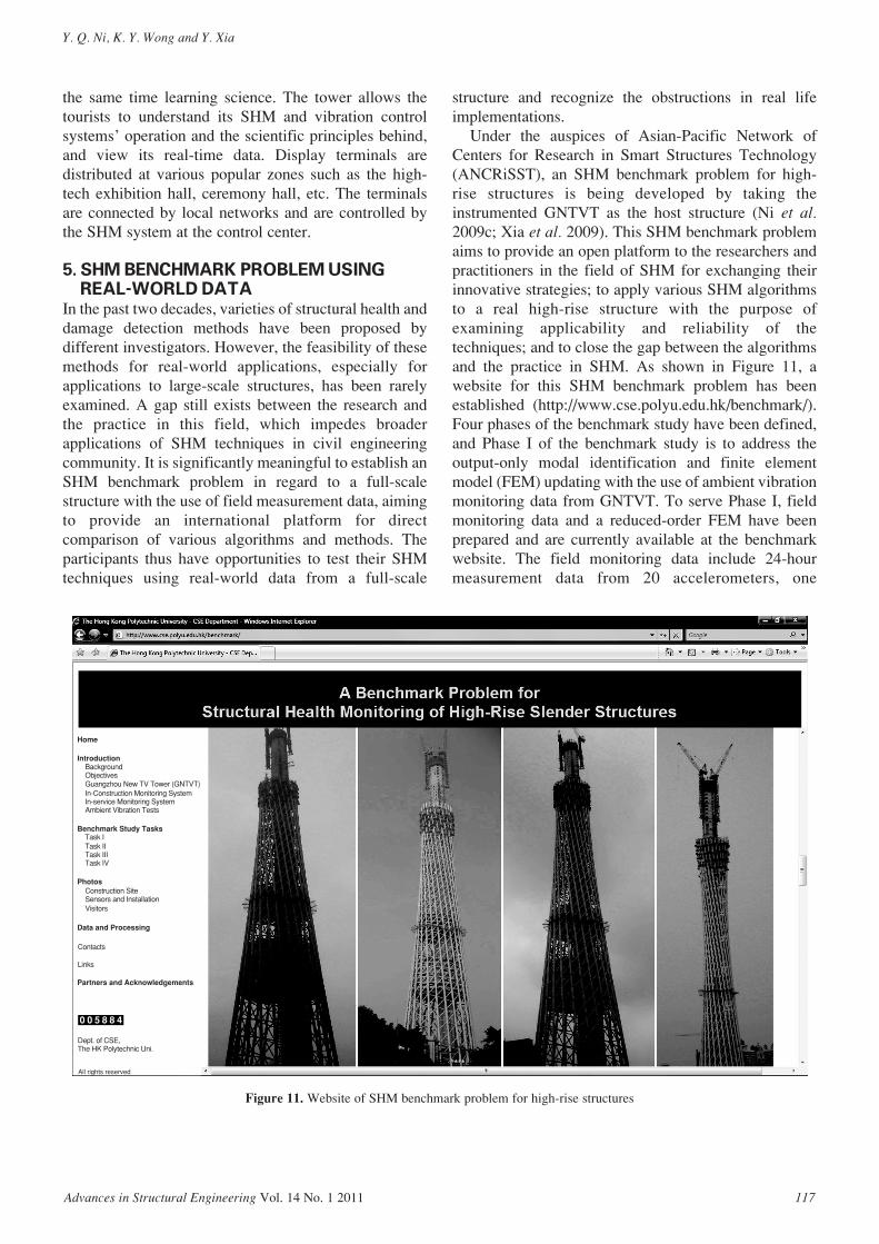
Under the auspices of Asian-Pacific Network ofCenters for Research in Smart Structures Technology(ANCRiSST), an SHM benchmark problem for high-rise structures is being developed by taking theinstrumented GNTVT as the host structure (Ni et al.2009c; Xia et al. 2009). This SHM benchmark problemaims to provide an open platform to the researchers andpractitioners in the field of SHM for exchanging theirinnovative strategies; to apply various SHM algorithmsto a real high-rise structure with the purpose ofexamining applicability and reliability of thetechniques; and to close the gap between the algorithmsand the practice in SHM. As shown in Figure 11, awebsite for this SHM benchmark problem has beenestablished (http://www.cse.polyu.edu.hk/benchmark/).Four phases of the benchmark study have been defined,and Phase I of the benchmark study is to address theoutput-only modal identification and finite elementmodel (FEM) updating with the use of ambient vibrationmonitoring data from GNTVT. To serve Phase I, fieldmonitoring data and a reduced-order FEM have beenprepared and are currently available at the benchmarkwebsite. The field monitoring data include 24-hourmeasurement data from 20 accelerometers, one
Home
Introduction
Benchmark Study Tasks
Photos
Data and Processing
Contacts
Links
Partners and Acknowledgements
Dept. of CSE,The HK Polytechnic Uni.
All rights reserved
BackgroundObjectivesGuangzhou New TV Tower (GNTVT)In-Construction Monitoring SystemIn-service Monitoring SystemAmbient Vibration Tests
Task ITask IITask IIITask IV
Construction SiteSensors and InstallationVisitors
0 0 5 8 8 4
Figure 11. Website of SHM benchmark problem for high-rise structures
Health Checks through Landmark Bridges to Sky-high Structures
118 Advances in Structural Engineering Vol. 14 No. 1 2011
anemometer and one temperature sensor. The reduced-order FEM is deduced from a validated full-scale 3DFEM consisting of 122,476 elements, 84,370 nodes and505,164 degrees of freedom (DOFs). With a total of 185DOFs, the reduced-order FEM comprises 37 beamelements and 37 nodes having 5 DOFs each. A goodagreement between the reduced-order and full-scaleFEMs has been achieved in terms of both modalfrequencies and mode shapes for the first 15 modes(Lin et al. 2010).
6. CONCLUDING REMARKSThe evolution of designing and implementing SHMsystems for large-scale bridges in Hong Kong spanningover ten years has been summarized. The bridge healthmonitoring systems are currently considered as anintegrated part of bridge operation, inspection, andmaintenance and have been included as a standardmechatronic system in the design and construction oflarge-scale and multidisciplinary bridge projects inHong Kong. The experience gained in the design,installation, operation, maintenance, and upgrading ofthe existing SHM systems has a significant influence onthe development of new SHM systems in Hong Kongand the Chinese mainland. The bridge SHM practiceand experiences have been extended to thedevelopment of SHM systems for high-rise structures.As such an example, a sophisticated long-term SHMsystem has been designed and implemented on theGuangzhou New TV Tower (GNTVT) with a totalheight of 610 m. This system exercises a pioneeringSHM practice that integrates in-constructionmonitoring and in-service monitoring, and has beendesigned to have a special function of verifying theeffectiveness of vibration control devices installed onthe tower. In addition, innovative fiber optic sensors,and vision-based sensing and wireless monitoringtechniques have been practiced in this project. An SHMbenchmark problem for high-rise structures has beeninitiated by taking the instrumented GNTVT as the hoststructure.
ACKNOWLEDGEMENTSThis paper is dedicated to respectable Prof. J. M. Ko onthe occasion of his retirement from The Hong KongPolytechnic University. The authors are also grateful toProf. M. L. Wang (Northeastern University), Prof. K. H.Law (Stanford University), Prof. Y. Wang (GeorgiaInstitute of Technology), Prof. J. P. Lynch (Universityof Michigan), and Prof. B. F. Spencer, Jr. (University ofIllinois at Urbana-Champaign). Special thanks are dueto Dr. Y. H. Cao (Northeastern University). The workdescribed in this paper was supported in part by a grant
from the Research Grants Council of the Hong KongSpecial Administrative Region, China (Project No.PolyU 5263/08E) and partially by a grant from TheHong Kong Polytechnic University through theDevelopment of Niche Areas Programme (Project No.1-BB68). These supports are greatly acknowledged.
REFERENCESKo, J.M. and Ni, Y.Q. (2005). “Technology developments in
structural health monitoring of large-scale bridges”, Engineering
Structures, Vol. 27, No. 12, pp. 1715–1725.
Lin, W., Ni, Y.Q., Xia, Y. and Chen, W.H. (2010). “Field
measurement data and a reduced-order finite element model for
Task I of the SHM benchmark problem for high-rise structures”,
Proceedings of the 5th World Conference on Structural Control
and Monitoring, Tokyo, Japan, July. (CD-ROM).
Ni, Y.Q. (2010a). “Structural health monitoring for civil
infrastructure systems: from research to application”,
Proceedings of the 5th European Workshop on Structural Health
Monitoring, Sorrento, Naples, Italy, June–July, pp. 6-17.
Ni, Y.Q. (2010b). “Structural health monitoring: research,
applications, and integration with renewable energy
technologies”, Presented at Center for Information Technology
Research in the Interest of Society (CITRIS), University of
California, Berkeley, CA, USA, April.
Ni, Y.Q., Xia, Y., Chen, W.H., Lu, Z.R., Liao, W.Y. and Ko, J.M.
(2009a). “Monitoring of wind properties and dynamic responses
of a supertall structure during typhoon periods”, Proceedings of
the 4th International Conference on Structural Health Monitoring
and Intelligent Infrastructure, Zurich, Switzerland, July.
(CD-ROM).
Ni, Y.Q., Xia, Y., Liao, W.Y. and Ko, J.M. (2009b). “Technology
innovation in developing the structural health monitoring system
for Guangzhou New TV Tower”, Structural Control and Health
Monitoring, Vol. 16, No. 1, pp. 73–98.
Ni, Y.Q., Xia, Y., Lin, W., Chen, W.H. and Ko, J.M. (2009c).
“ANCRiSST benchmark problem on structural health monitoring
of high-rise slender structures – Phase I: reduced-order finite
element model”, Proceedings of the 5th International Workshop
on Advanced Smart Materials and Smart Structures Technology,
Boston, Massachusetts, USA, July. (CD-ROM).
Shao, X.P., Guo, B.L. and Ni, Y.Q. (2010). “Instrumentation for
reinforced concrete durability monitoring of Qingdao Bay
Bridge”, Proceedings of the 5th International Conference on
Bridge Maintenance, Safety and Management, Philadelphia,
Pennsylvanian, USA, July. (CD-ROM).
Wong, K.Y. (2004). “Instrumentation and health monitoring of
cable-supported bridges”, Structural Control and Health
Monitoring, Vol. 11, No. 2, pp. 91–124.
Wong, K.Y. (2006). “Criticality and vulnerability analyses of Tsing
Ma Bridge”, Proceedings of the International Conference on
Bridge Engineering – Challenges in the 21st Century, Hong
Kong, China, December. (CD-ROM).

Y. Q. Ni, K. Y. Wong and Y. Xia
Advances in Structural Engineering Vol. 14 No. 1 2011 119
Wong, K.Y. (2007). “Design of a structural health monitoring
system for long-span bridges”, Structure and Infrastructure
Engineering, Vol. 3, No. 2, pp. 169–185.
Wong, K.Y. and Ni, Y.Q. (2009a). “Modular architecture of
structural health monitoring system for cable-supported bridges”,
Encyclopedia of Structural Health Monitoring, C. Boller, F.K.
Chang and Y. Fujino, eds., John Wiley & Sons, Chichester, UK,
Vol. 5, pp. 2089–2105.
Wong, K.Y. and Ni, Y.Q. (2009b). “Structural health monitoring of
cable-supported bridges in Hong Kong”, Structural Health
Monitoring of Civil Infrastructure Systems, V.M. Karbhari and F.
Ansari, eds., Woodhead Publishing, Cambridge, UK, pp.
371–411.
Xia, Y., Ni, Y.Q., Ko, J.M., Liao, W.Y. and Chen, W.H. (2009).
“ANCRiSST benchmark problem on structural health
monitoring of high-rise slender structures – Phase I: field
vibration measurement”, Proceedings of the 5th International
Workshop on Advanced Smart Materials and Smart
Structures Technology, Boston, Massachusetts, USA, July.
(CD-ROM).


![[Vasant Matsagar (Eds.)] Advances in Structural en(BookZZ.org)](https://img.pdfslide.net/doc/110x75/563db89c550346aa9a954785/vasant-matsagar-eds-advances-in-structural-enbookzzorg.jpg)