Embed Size (px)
Citation preview
1© 2016 V1 Media, www.informedinfrastructure.com
his third-party assessment of how AutoCAD Civil 3D and InfraWorks 360 together impact civil engineering workflows was commissioned by Au-todesk. The editorial team at Informed Infrastruc-ture solicited reviewers immersed in the software
on a daily basis, coordinating their review of the software with project scenarios that mimic how they use these tools every day and then summarizing that input in the following report.
This report is not a comparison test. The report details the evolution of the software, efficiency improve-ments inherent with software that focuses on work-flows, and the time savings that can be achieved across many functions and design progressions. The compari-son is meant to illustrate how these software packages work in tandem on preliminary and detailed design, and to convey time savings and the elimination of tedium. Performance improvements are relayed here, but no ef-fort was made to standardize computer hardware or the size and complexity of these project scenarios, so results on time savings vary, and some fluctuation on projects may be experienced.
Executive SummaryThe advancements of modeling software travel along
a continuum of improvements on how users conceptu-alize complex infrastructure projects, collaborate with stakeholders and deliver designs that improve infra-structure performance. Time savings is the constant bot-tom line, but not the only consideration, in determining the success of these advancements.
Executives and managers are concerned with im-proving the outcomes of their design process against the time it takes for their teams to design, because the time of personnel is their single-largest cost, and their team’s capacity for work is the single-largest constraint
T
Sponsored by
BENCHMARK STUDY
KEY FINDINGS- When combined with AutoCAD Civil 3D, InfraWorks 360 delivered significant time savings in preliminary design and early detailed design processes. Reviewers were able to quickly produce intelligent design models as well as high-quality visuals of their project in the context of real-world surroundings.
- Reviewers pointed to the ability to easily interface with stakeholders as a key benefit of incorporating InfraWorks 360 in their workflows. The ability to bring up data for a project site and optioneer design alternatives early on in the process, even during meetings, was a compounding time saver as it sped the time to design consensus.
- Each reviewer pursued his or her own individualized work-flows, and each was dealing with different geographies with different climate and code requirements. Despite these differences, they each saw time savings and im-provements to the quality of their designs when combining AutoCAD Civil 3D and InfraWorks 360.
- AutoCAD Civil 3D, Autodesk’s civil design software, remains the primary tool for the completion of detailed design and documentation. In addition, its ability to support 2D and 3D provides the means to bridge CAD-based workflows while navigating new BIM approaches to project delivery.
Advancing Civil Infrastructure Design WorkflowsAutoCAD Civil 3D and InfraWorks 360 Combine for Improved Outcomes
© 2016 V1 Media, www.informedinfrastructure.com2
on growth. Those doing design work are interested in progressions that reduce the tedium of their task and increase their understanding of the site and other design constraints while improving their ability to deliver on design objectives. The constant give and take to achieve the best possible design in a streamlined fashion is further constrained by the ability to convey the design to owners and manage expectations while having the flexibility to adjust the design based on feedback and concerns.
To quantify the productivity improvements of using AutoCAD Civil 3D in tandem with InfraWorks 360, re-viewers first designed their projects solely in AutoCAD Civil 3D and then began again with InfraWorks 360 alongside AutoCAD Civil 3D. In most project scenarios, there was a time savings when starting with InfraWorks 360’s preliminary design capabilities.
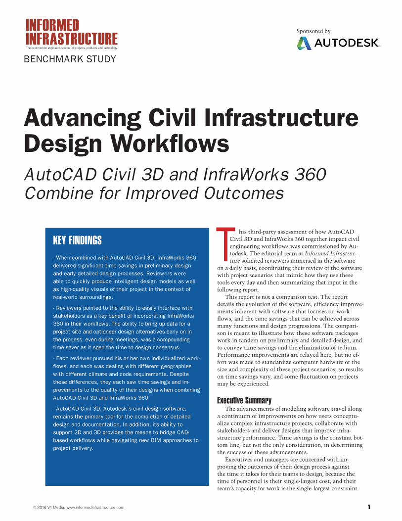
Our reviewers were comprised of one person who trains users on both AutoCAD Civil 3D and InfraWorks 360, a person who started his own company to increase
his use of model-based design and InfraWorks 360 to drive project efficiency, and a beta tester of the Infra-Works 360 software who has been lobbying his firm to acquire the technology so he can use the software on a daily basis. The results of the study showed time sav-ings when InfraWorks 360 was employed in preliminary design phases. The time saved on an airport roadway design was 1 hour and 55 minutes; the time saved on a new roadway in Austin, Texas, was 9 hours; and a small subdivision saved 6 hours and 10 minutes.
The time savings were not at the forefront of any of our reviewers minds, however, as the benefit they focused on most was their improved ability to interface with owners and respond more quickly to their needs through the ability of InfraWorks 360 to present the project site and design details in a flexible manner that allows them to rapidly update the design (often in real time) based on feedback.
Productivity improvements achieved will vary based on the project’s complexity and size, hardware capacity, software performance, users’ skill and knowledge of the software, and the ability of owners and other stakehold-ers to convey requirements and reach consensus on a constructible design. The tandem capability of Infra-Works 360’s preliminary design workflows in realistic 3D, alongside the detailed design capabilities of Auto-CAD Civil 3D, have proven to reduce the time it takes from beginning to end of the process.
Enhancing CapabilitiesIt’s not a matter of AutoCAD Civil 3D vs. InfraWorks
360, rather it’s all about the tools together. The functions of establishing existing conditions, preliminary road design, preliminary stream crossing and preliminary stormwater drainage design all can be done in both prod-ucts. For the purpose of comparison, the tools were put head-to-head on these functions, however, in multiple instances (as noted below), reviewers combined functions across the products to progress their projects.
Although a side-by-side comparison is instructive re-garding the efficiency of different tasks within the differ-ent software packages, this workflow comparison does not tell the entire story. In addition to the preliminary design elements within InfraWorks 360, it also offers a host of functionality that is not part of the AutoCAD Civil 3D software, including analytics, Web publishing and collaboration tools. Similarly, AutoCAD Civil 3D is the only place for detailed design and documentation,
which takes up nearly 30 percent of the time for a typi-cal infrastructure project.
InfraWorks 360 has the ability to build and analyze multiple designs quickly, so it offers the opportunity to give your clients choices early and often in the design process. It also offers the ability to present these choices visually in a way that communicates without interpretation.
The inclusion of analytics for roads, bridge design, storm systems and other elements offers quantified answers to your design decisions, determining such things as the turn radius of a road based on speed, the height clearance for a bridge and the flow performance of pipe for a storm system. These simulation capabilities are all easily accessible to test the model as you design. The calculations provide guidance for your design deci-sions, and the analytical output provides backup that can be shared to illustrate why certain choices were made.
Involving clients in the process in real time as you de-sign is possible through the collaboration tools that are part of InfraWorks 360. With team editing, an entire group can collaborate on the design of a project. The full InfraWorks 360 capabilities aren’t needed to share the model with those who aren’t designers, as the model can be shared via a Web browser or mobile device. There is also a Design Feed function to make comments or suggest changes, in effect creating a design punch list for the designers to understand what has been approved and what still needs attention.
3© 2016 V1 Media, www.informedinfrastructure.com
Keeping team members and stakeholders informed and involved throughout the design process is a key capability of InfraWorks 360 that improves the preliminary design process and the quality of the design. The earlier involve-ment and interaction can save thousands of dollars on a project by speeding consensus and reducing change orders, while also streamlining time to project approval.
Workflow ApproachAutoCAD Civil 3D represents a long legacy of design
tools that output construction documentation and production sheets to match deliverables required by gov-ernments and contractors to realize a design through to its final delivery. InfraWorks 360 has introduced a wholly 3D workflow that meshes well with the requirements of preliminary design to understand site constraints; work through scenarios that weigh design options against performance and cost; and convey the resulting design to owners, stakeholders and the public.
Separating the workflow of preliminary and detailed design is a natural break in the overall engineering design process. Conceptual and preliminary design phases often are precursors to winning the overall design work. Because it doesn’t always result in work won, the less time it requires, the fewer resources are wasted if you don’t win the work.
Detailed design naturally requires an added level of rigor, as it’s the phase that gets signed off by engineers with that added liability. Naturally, engineers will want full control over all aspects of the design, with the ability to make changes to each element. This methodical review of the design is the more-compelling element for engineers and is critical at the end of the design process.
Preliminary DesignThe amount of real-world inputs in the design process
is a major change to prior project work. Previously, a site survey would collect boundary points and elevations, and the process might also include an aerial image for reference. But with modern capture technology, projects start with a detailed 3D model of the site with millions of points for reference. Efficiency is greatly improved with this new era of easy reality capture, and it’s most helpful from the very beginning.
Although such data can be imported and managed in AutoCAD Civil 3D, InfraWorks 360 shines in its ability to import and visualize data. By providing a centralized visualization hub for project information, InfraWorks 360 allows for quicker realization of design constraints as well as a means to analyze and explore alternatives.
Earthwork costs are often the most-expensive construc-tion line item, particularly on land-development projects, so fairly accurate quantity estimates are performed starting at the preliminary design phase. InfraWorks 360 has the ability to quickly determine earthwork quantities in order to calculate costs.
Detailed DesignWhen porting preliminary design work from
InfraWorks 360 to AutoCAD Civil 3D, nearly all of the design information is preserved, which speeds the
transition from preliminary to detailed design. AutoCAD Civil 3D is the place to complete detailed design work and generate needed documentation, including plan sets. Today, InfraWorks 360 does not have this ability, as it isn’t designed to fulfill this role.
Quantified ComparisonAutodesk commissioned this benchmarking study
to help validate its own internal review of the workflow between toolsets and understand how AutoCAD Civil 3D and InfraWorks 360 are being used alongside one another in daily practice. Our reviewers use the software on a daily basis, producing work for civil engineering projects and pushing the software through its paces on a wide variety of projects.
This third-party assessment of design workflows using just AutoCAD Civil 3D and the same workflows using InfraWorks 360 alongside AutoCAD Civil 3D allowed our reviewers to choose their own project, with the assign-ment to design specific elements within the project space and move the project forward from preliminary design to detailed design and then on to documentation, including in-context visualization.
The intent was to conduct the exercise as if InfraWorks 360 was not available and then to compare the same process with InfraWorks 360 in the mix. The work was detailed via notes on the steps taken through both scenar-ios as well as details on efficiencies, if any, gained using InfraWorks 360 during the preliminary design phase. The handoff between the software tools also was detailed to document how the tools work in tandem.
For each effort, reviewers recorded the time and efficien-cy gains across the following progressions and tasks:• Establishing existing conditions with use of freely avail-
able data for a project size between 50 acres and one square mile. Compiling existing conditions with terrain, major buildings, roads, railroads, linear water features and major closed water features.
• Laying out the preliminary road design between 1,000 feet and two miles, including two roads and one inter-section, using horizontal road definitions and accepted geometric engineering parameters for curves and slopes, representing roads as 3D models, grading so reasonable cut and fill is achieved, and completing clean intersec-tions.
• Completing a preliminary stream crossing represented by a culvert designed for a 100-year storm with proper culvert entrance and exit locations as well as a visual representation of the culvert, road and channel.
• Providing a preliminary storm-drainage design with inlets, manholes and pipes for water on the road surface only, including inlets for adequate capture that mini-mizes bypass flow, pipes sized to predicted flows and outfalls to release collected drainage.Each reviewer progressed the projects from preliminary
design to detailed design, documentation and in-context visualization.
Individual and IntegratedBefore getting into each reviewer’s specific projects
and their individual findings, some work was done to
© 2016 V1 Media, www.informedinfrastructure.com4
summarize the workflow that Autodesk tested internal-ly. This Autodesk benchmarking study formed the basis for this benchmarking assignment, but none of the re-sults from Autodesk’s study were shared with reviewers, nor were any of the design assumptions shared for the creation of their project spaces.
This overview presents the workflow that Autodesk devised, with some details about the tasks conducted in each piece of software, and the time it took to complete each task. Integration and handoffs between each soft-ware package are noted, along with some details about the steps and scenarios where efficiency was achieved. AutoCAD Civil 3D and InfraWorks 360 combine and assist each other in overall design efficiency.
Establishing Existing ConditionsIncorporating existing conditions has become much
easier over time. There are many clearinghouses of GIS data and aerial imagery available from federal, state and local sources. This detail is most helpful in the prelimi-nary design process.
After establishing the existing conditions in a prelim-inary sense in InfraWorks 360, you then have to go to a more accurate level as the design progresses with survey information that needs to be imported and processed within AutoCAD Civil 3D, which then can be returned back to InfraWorks 360 for visualization.
Preliminary Road DesignRoad design involves first getting an
accurate surface, and then determining road alignment and profile. Intersections add complexity.
After the preliminary design of the roadway location in InfraWorks 360, fine tuning of the profile and intersections may be required, superelevation may need to be applied, assemblies must be developed, and sections need to be cut. All of this detailed design and documentation has to happen in AutoCAD Civil 3D. If you’re only using AutoCAD Civil 3D, you lose the ability of InfraWorks 360 to quickly create the roads. However, you need to go from InfraWorks 360 to AutoCAD Civil 3D to do the detailed design, documentation and creation of con-struction documents.
Preliminary Stream CrossingThe first step to determining a stream
crossing is the delineation of a watershed so the appropriate crossing can be determined and the flows for 100-year flood events can be modeled.
The data generated in InfraWorks 360 for the culverts now need to go to AutoCAD Civil 3D to create construction documents, including details on how the culvert’s end walls are constructed, and labels need to be added to provide a construction document
on how to build and install each culvert, which can’t be done in InfraWorks 360. AutoCAD Civil 3D is also the place to add more-detailed grading details for the inlet and outlet of the culvert. Again, the more-accurate design created in AutoCAD Civil 3D can be moved back over to InfraWorks 360 for final visualization.
Preliminary Storm DesignThe process of stormwater drainage design takes in the
watershed information as in the aforementioned stream crossing. This step involves the design of inlets, manholes and pipes, along with analyzing the flow for the proper pipe diameter and cost estimation.
In InfraWorks 360, the pipes and structures are quickly created, but these are all laid out based on rules and design assumptions. There will need to be fine tuning, and those adjustments are done in AutoCAD Civil 3D, where you can also add labels and create construction documents for how to install the stormwater system. When you add this more-detailed model back into InfraWorks 360, it gives you the ability to visualize all the subsurface elements in exactly the position for the final design, further aiding communication to the construction crews.
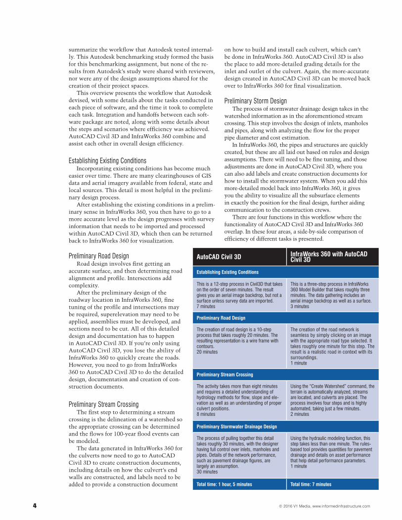
There are four functions in this workflow where the functionality of AutoCAD Civil 3D and InfraWorks 360 overlap. In these four areas, a side-by-side comparison of efficiency of different tasks is presented.
AutoCAD Civil 3D InfraWorks 360 with AutoCAD Civil 3D
Establishing Existing Conditions
This is a 12-step process in Civil3D that takes on the order of seven minutes. The result gives you an aerial image backdrop, but not a surface unless survey data are imported.7 minutes
This is a three-step process in InfraWorks 360 Model Builder that takes roughly three minutes. The data gathering includes an aerial image backdrop as well as a surface.3 minutes
Preliminary Road Design
The creation of road design is a 10-step process that takes roughly 20 minutes. The resulting representation is a wire frame with contours.20 minutes
The creation of the road network is seamless by simply clicking on an image with the appropriate road type selected. It takes roughly one minute for this step. The result is a realistic road in context with its surroundings.1 minute
Preliminary Stream Crossing
The activity takes more than eight minutes and requires a detailed understanding of hydrology methods for flow, slope and ele-vation as well as an understanding of proper culvert positions.8 minutes
Using the “Create Watershed” command, the terrain is automatically analyzed, streams are located, and culverts are placed. The process involves four steps and is highly automated, taking just a few minutes.2 minutes
Preliminary Stormwater Drainage Design
The process of pulling together this detail takes roughly 30 minutes, with the designer having full control over inlets, manholes and pipes. Details of the network performance, such as pavement drainage figures, are largely an assumption.30 minutes
Using the hydraulic modeling function, this step takes less than one minute. The rules-based tool provides quantities for pavement drainage and details on asset performance that help detail performance parameters. 1 minute
Total time: 1 hour, 5 minutes Total time: 7 minutes
5© 2016 V1 Media, www.informedinfrastructure.com
As you can see from the above comparison of prelimi-nary design functions, there’s a distinct efficiency advan-tage including InfraWorks 360 for the preliminary design phase. The documentation and visualization steps outlined below make the important point that these toolsets are designed to complement each other. Admit-tedly, nearly all authorities require design documenta-tion in the form of drawings and plans. However, more authorities are also asking for 3D presentations given their ability to effectively communicate to stakeholders, including those accustomed to reading 2D drawings and plans and those who are not.
Design DocumentationAutoCAD Civil 3D is the place to create project
sheets to communicate details with authorities and contractors. InfraWorks 360 allows users to design in context, but does not output final construction docu-ments. Civil 3D contains tools for survey data manage-ment and processing, bidding and construction phases as well as drafting and document creation, including labeling and outputs that adhere to graphical standards for documentation of profiles and cross sections. These tools include the ability to customize a template, and they are an automated output from the design space in
the view, and with the detail, specified. Documentation for this scenario took two hours.
Visual CommunicationAn ability to visually represent the project space is
helpful throughout the process. Civil 3D provides rep-resentations in traditional sheet-based documents and line drawings, and not textured and realistic 3D models. Other software, such as InfraWorks 360, is needed to provide a realistic rendering or animation.
InfraWorks 360 provides a centralized point where stakeholders identify project needs, analyze existing infrastructure using a data-rich model, and put together a preliminary design quickly to test different options and analyze alternatives. To aid the realism in Infra-Works 360, there are easy-to-use tools to model details such as wind direction and speed, sun position, moving clouds, water surfaces and sunsets. Visualization took two hours.
With models in InfraWorks 360, there were clear efficiency and quality benefits of using that model in detailed design and documentation workflows within AutoCAD Civil 3D to produce construction documents. Similarly, there were advantages of shareable visualiza-tions for marketing and public outreach.
Project ExamplesThe aforementioned time savings are real and significant, however, they don’t directly relate and reflect daily practice,
as each user takes individualized approaches, although all steps are followed.Each reviewer chose his or her own project space and workflow to illustrate a diversity of project types and geographies as well as their
natural workflow for completing work. This report is simply a summary, with some details related for each step. A more-detailed step-by-step accounting for these projects can be found online on the Informed Infrastructure website. Be sure to check out these resources, as the step-
by-step processes illustrated could help fine-tune individuals’ own approach to using these tools.
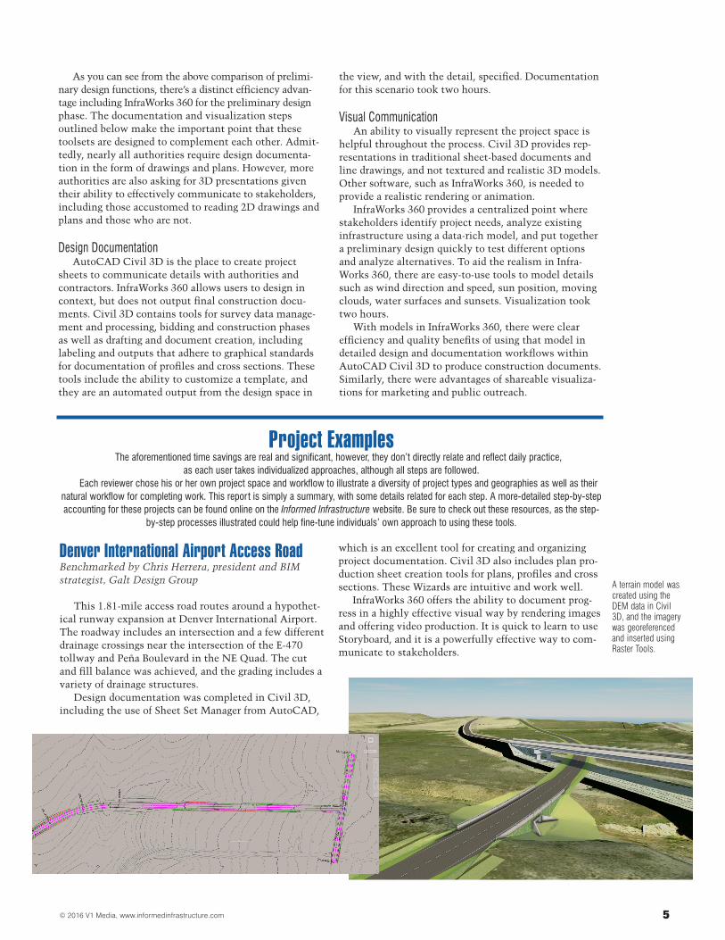
Denver International Airport Access RoadBenchmarked by Chris Herrera, president and BIM strategist, Galt Design Group
This 1.81-mile access road routes around a hypothet-ical runway expansion at Denver International Airport. The roadway includes an intersection and a few different drainage crossings near the intersection of the E-470 tollway and Peña Boulevard in the NE Quad. The cut and fill balance was achieved, and the grading includes a variety of drainage structures.
Design documentation was completed in Civil 3D, including the use of Sheet Set Manager from AutoCAD,
which is an excellent tool for creating and organizing project documentation. Civil 3D also includes plan pro-duction sheet creation tools for plans, profiles and cross sections. These Wizards are intuitive and work well.
InfraWorks 360 offers the ability to document prog-ress in a highly effective visual way by rendering images and offering video production. It is quick to learn to use Storyboard, and it is a powerfully effective way to com-municate to stakeholders.
A terrain model was created using the DEM data in Civil 3D, and the imagery was georeferenced and inserted using Raster Tools.
© 2016 V1 Media, www.informedinfrastructure.com6
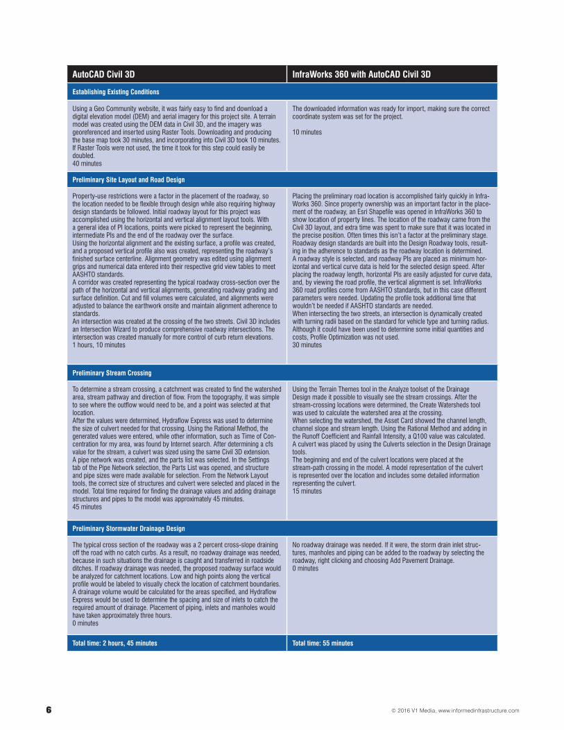
AutoCAD Civil 3D InfraWorks 360 with AutoCAD Civil 3D
Establishing Existing Conditions
Using a Geo Community website, it was fairly easy to find and download a digital elevation model (DEM) and aerial imagery for this project site. A terrain model was created using the DEM data in Civil 3D, and the imagery was georeferenced and inserted using Raster Tools. Downloading and producing the base map took 30 minutes, and incorporating into Civil 3D took 10 minutes. If Raster Tools were not used, the time it took for this step could easily be doubled.40 minutes
The downloaded information was ready for import, making sure the correct coordinate system was set for the project.
10 minutes
Preliminary Site Layout and Road Design
Property-use restrictions were a factor in the placement of the roadway, so the location needed to be flexible through design while also requiring highway design standards be followed. Initial roadway layout for this project was accomplished using the horizontal and vertical alignment layout tools. With a general idea of PI locations, points were picked to represent the beginning, intermediate PIs and the end of the roadway over the surface. Using the horizontal alignment and the existing surface, a profile was created, and a proposed vertical profile also was created, representing the roadway’s finished surface centerline. Alignment geometry was edited using alignment grips and numerical data entered into their respective grid view tables to meet AASHTO standards. A corridor was created representing the typical roadway cross-section over the path of the horizontal and vertical alignments, generating roadway grading and surface definition. Cut and fill volumes were calculated, and alignments were adjusted to balance the earthwork onsite and maintain alignment adherence to standards.An intersection was created at the crossing of the two streets. Civil 3D includes an Intersection Wizard to produce comprehensive roadway intersections. The intersection was created manually for more control of curb return elevations.1 hours, 10 minutes
Placing the preliminary road location is accomplished fairly quickly in Infra-Works 360. Since property ownership was an important factor in the place-ment of the roadway, an Esri Shapefile was opened in InfraWorks 360 to show location of property lines. The location of the roadway came from the Civil 3D layout, and extra time was spent to make sure that it was located in the precise position. Often times this isn’t a factor at the preliminary stage.Roadway design standards are built into the Design Roadway tools, result-ing in the adherence to standards as the roadway location is determined. A roadway style is selected, and roadway PIs are placed as minimum hor-izontal and vertical curve data is held for the selected design speed. After placing the roadway length, horizontal PIs are easily adjusted for curve data, and, by viewing the road profile, the vertical alignment is set. InfraWorks 360 road profiles come from AASHTO standards, but in this case different parameters were needed. Updating the profile took additional time that wouldn’t be needed if AASHTO standards are needed.When intersecting the two streets, an intersection is dynamically created with turning radii based on the standard for vehicle type and turning radius. Although it could have been used to determine some initial quantities and costs, Profile Optimization was not used. 30 minutes
Preliminary Stream Crossing
To determine a stream crossing, a catchment was created to find the watershed area, stream pathway and direction of flow. From the topography, it was simple to see where the outflow would need to be, and a point was selected at that location. After the values were determined, Hydraflow Express was used to determine the size of culvert needed for that crossing. Using the Rational Method, the generated values were entered, while other information, such as Time of Con-centration for my area, was found by Internet search. After determining a cfs value for the stream, a culvert was sized using the same Civil 3D extension. A pipe network was created, and the parts list was selected. In the Settings tab of the Pipe Network selection, the Parts List was opened, and structure and pipe sizes were made available for selection. From the Network Layout tools, the correct size of structures and culvert were selected and placed in the model. Total time required for finding the drainage values and adding drainage structures and pipes to the model was approximately 45 minutes. 45 minutes
Using the Terrain Themes tool in the Analyze toolset of the Drainage Design made it possible to visually see the stream crossings. After the stream-crossing locations were determined, the Create Watersheds tool was used to calculate the watershed area at the crossing. When selecting the watershed, the Asset Card showed the channel length, channel slope and stream length. Using the Rational Method and adding in the Runoff Coefficient and Rainfall Intensity, a Q100 value was calculated. A culvert was placed by using the Culverts selection in the Design Drainage tools. The beginning and end of the culvert locations were placed at the stream-path crossing in the model. A model representation of the culvert is represented over the location and includes some detailed information representing the culvert.15 minutes
Preliminary Stormwater Drainage Design
The typical cross section of the roadway was a 2 percent cross-slope draining off the road with no catch curbs. As a result, no roadway drainage was needed, because in such situations the drainage is caught and transferred in roadside ditches. If roadway drainage was needed, the proposed roadway surface would be analyzed for catchment locations. Low and high points along the vertical profile would be labeled to visually check the location of catchment boundaries. A drainage volume would be calculated for the areas specified, and Hydraflow Express would be used to determine the spacing and size of inlets to catch the required amount of drainage. Placement of piping, inlets and manholes would have taken approximately three hours. 0 minutes
No roadway drainage was needed. If it were, the storm drain inlet struc-tures, manholes and piping can be added to the roadway by selecting the roadway, right clicking and choosing Add Pavement Drainage.0 minutes
Total time: 2 hours, 45 minutes Total time: 55 minutes
7© 2016 V1 Media, www.informedinfrastructure.com
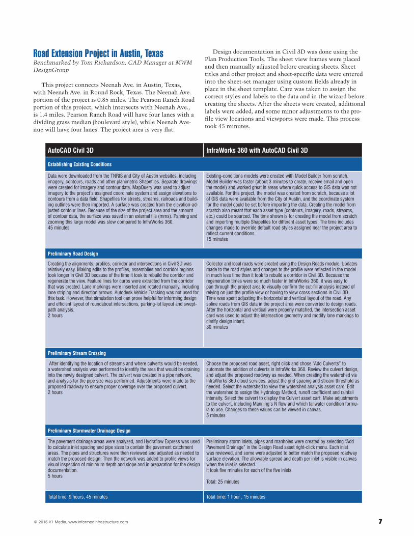
Road Extension Project in Austin, TexasBenchmarked by Tom Richardson, CAD Manager at MWM DesignGroup
This project connects Neenah Ave. in Austin, Texas, with Neenah Ave. in Round Rock, Texas. The Neenah Ave. portion of the project is 0.85 miles. The Pearson Ranch Road portion of this project, which intersects with Neenah Ave., is 1.4 miles. Pearson Ranch Road will have four lanes with a dividing grass median (boulevard style), while Neenah Ave-nue will have four lanes. The project area is very flat.
Design documentation in Civil 3D was done using the Plan Production Tools. The sheet view frames were placed and then manually adjusted before creating sheets. Sheet titles and other project and sheet-specific data were entered into the sheet-set manager using custom fields already in place in the sheet template. Care was taken to assign the correct styles and labels to the data and in the wizard before creating the sheets. After the sheets were created, additional labels were added, and some minor adjustments to the pro-file view locations and viewports were made. This process took 45 minutes.
AutoCAD Civil 3D InfraWorks 360 with AutoCAD Civil 3D
Establishing Existing Conditions
Data were downloaded from the TNRIS and City of Austin websites, including imagery, contours, roads and other planimetric Shapefiles. Separate drawings were created for imagery and contour data. MapQuery was used to adjust imagery to the project’s assigned coordinate system and assign elevations to contours from a data field. Shapefiles for streets, streams, railroads and build-ing outlines were then imported. A surface was created from the elevation-ad-justed contour lines. Because of the size of the project area and the amount of contour data, the surface was saved in an external file (mms). Panning and zooming this large model was slow compared to InfraWorks 360.45 minutes
Existing-conditions models were created with Model Builder from scratch. Model Builder was faster (about 3 minutes to create, receive email and open the model) and worked great in areas where quick access to GIS data was not available. For this project, the model was created from scratch, because a lot of GIS data were available from the City of Austin, and the coordinate system for the model could be set before importing the data. Creating the model from scratch also meant that each asset type (contours, imagery, roads, streams, etc.) could be sourced. The time shown is for creating the model from scratch and importing multiple Shapefiles for different asset types. The time includes changes made to override default road styles assigned near the project area to reflect current conditions.15 minutes
Preliminary Road Design
Creating the alignments, profiles, corridor and intersections in Civil 3D was relatively easy. Making edits to the profiles, assemblies and corridor regions took longer in Civil 3D because of the time it took to rebuild the corridor and regenerate the view. Feature lines for curbs were extracted from the corridor that was created. Lane markings were inserted and rotated manually, including lane striping and direction arrows. Autodesk Vehicle Tracking was not used for this task. However, that simulation tool can prove helpful for informing design and efficient layout of roundabout intersections, parking-lot layout and swept-path analysis.2 hours
Collector and local roads were created using the Design Roads module. Updates made to the road styles and changes to the profile were reflected in the model in much less time than it took to rebuild a corridor in Civil 3D. Because the regeneration times were so much faster in InfraWorks 360, it was easy to pan through the project area to visually confirm the cut-fill analysis instead of relying on just the profile view or having to view cross sections in Civil 3D.Time was spent adjusting the horizontal and vertical layout of the road. Any spline roads from GIS data in the project area were converted to design roads. After the horizontal and vertical were properly matched, the intersection asset card was used to adjust the intersection geometry and modify lane markings to clarify design intent.30 minutes
Preliminary Stream Crossing
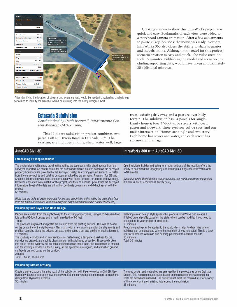
After identifying the location of streams and where culverts would be needed, a watershed analysis was performed to identify the area that would be draining into the newly designed culvert. The culvert was created in a pipe network, and analysis for the pipe size was performed. Adjustments were made to the proposed roadway to ensure proper coverage over the proposed culvert. 2 hours
Choose the proposed road asset, right click and chose “Add Culverts” to automate the addition of culverts in InfraWorks 360. Review the culvert design, and adjust the proposed roadway as needed. When creating the watershed via InfraWorks 360 cloud services, adjust the grid spacing and stream threshold as needed. Select the watershed to view the watershed analysis asset card. Edit the watershed to assign the Hydrology Method, runoff coefficient and rainfall intensity. Select the culvert to display the Culvert asset cart. Make adjustments to the culvert, including Manning’s N flow and which tailwater condition formu-la to use. Changes to these values can be viewed in canvas.5 minutes
Preliminary Stormwater Drainage Design
The pavement drainage areas were analyzed, and Hydraflow Express was used to calculate inlet spacing and pipe sizes to contain the pavement catchment areas. The pipes and structures were then reviewed and adjusted as needed to match the proposed design. Then the network was added to profile views for visual inspection of minimum depth and slope and in preparation for the design documentation. 5 hours
Preliminary storm inlets, pipes and manholes were created by selecting “Add Pavement Drainage” in the Design Road asset right-click menu. Each inlet was reviewed, and some were adjusted to better match the proposed roadway surface elevation. The allowable spread and depth per inlet is visible in canvas when the inlet is selected.It took five minutes for each of the five inlets.
Total: 25 minutes
Total time: 9 hours, 45 minutes Total time: 1 hour , 15 minutes
© 2016 V1 Media, www.informedinfrastructure.com8
Creating a video to show this InfraWorks project was quick and easy. Bookmarks of each view were added to a storyboard camera animation. After a few adjustments to pause at key locations, the movie was ready to export. InfraWorks 360 also offers the ability to share scenarios and models online. Although not needed for this project, scenario creation is easy and quick. The video creation took 15 minutes. Publishing the model and scenario, in-cluding supporting data, would have taken approximately 20 additional minutes.
After identifying the location of streams and where culverts would be needed, a watershed analysis was performed to identify the area that would be draining into the newly design culvert.
Estacada SubdivisionBenchmarked by Heidi Boutwell, Infrastructure Con-tent Manager, CADLearning
This 11.6-acre subdivision project combines two parcels off SE Divers Road in Estacada, Ore. The existing site includes a home, shed, water well, large
trees, existing driveway and a pasture over hilly terrain. The subdivision has 54 parcels for single- family homes; four 37-foot-wide streets with curb, gutter and sidewalk; three eyebrow cul-de-sacs; and one major intersection. Homes are single and two story. Each home has sewer and water, and each street has stormwater drainage.
AutoCAD Civil 3D InfraWorks 360 with AutoCAD Civil 3D
Establishing Existing Conditions
The design starts with a new drawing that will be the topo base, with plat drawings from the surveyor imported. An overall parcel for the new subdivision is created based on the surveyed property boundary line provided by the surveyor. Finally, an existing ground surface is created from the survey points and polyline contours provided by the surveyor. Research for GIS and Shapefile information was done, and some data was found for topo, structures and hydrology. However, only a few were useful for the project, and they do not line up well with the surveyed information. Most of the data are off in the coordinate conversion and did not assist with the project. 55 minutes
[Note that the tasks of creating parcels for the new subdivision and creating the ground surface from the points or contours from the survey can only be accomplished in AutoCAD Civil 3D.]
Opening Model Builder and going to a rough address of the location offers the ability to download the topography and existing buildings into InfraWorks 360. 5-10 minutes
[Note that while Model Builder can provide the real-world context for the project, the data is not as accurate as survey data.]
Preliminary Site Layout and Road Design
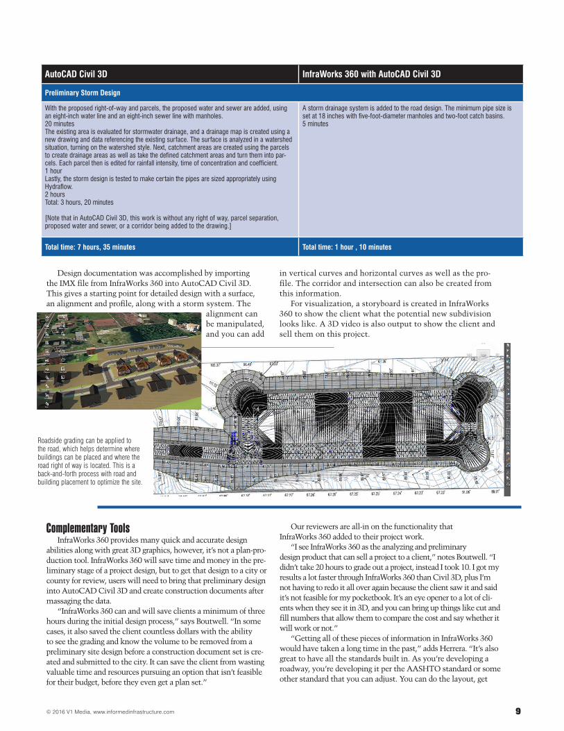
Parcels are created from the right-of-way to the existing property line, using 6,050-square-foot lots with a 55-foot frontage and a maximum depth of 90 feet. 1 hour The proposed alignment and profile are created from the existing surface. This will be based on the centerline of the right-of-way. This starts with a new drawing just for the alignments and profiles, sampled along the existing surface, and creating a surface profile for each alignment. 15 minutesThe roadway corridor and an intersection are created using a template. Baselines for the corridor are created, and each is given a region with a full road assembly. Those are broken into areas for the eyebrow cul-de-sacs and intersection areas. Next, the intersection is created, and the existing corridor is added. Finally, all the eyebrows are aligned, and a finished ground surface is created based on the corridor.2 hoursTotal: 3 hours, 45 minutes
Selecting a road design style speeds this process. InfraWorks 360 creates a finished ground profile based on the style, which can be modified if you need to change it to fit your project or local code. 15 minutesRoadside grading can be applied to the road, which helps to determine where buildings can be placed and where the road right of way is located. This is a back-and-forth process with road and building placement to optimize the site.15 minutesTotal: 30 minutes
Preliminary Stream Crossing
Create a culvert across the entry road of the subdivision with Pipe Networks in Civil 3D. Use Hydraflow Express to properly size the culvert. Edit the culvert back in the model to match the design from Hydraflow Express. 30 minutes
The road design and watershed are analyzed for the project area using Drainage Design. This requires cloud credits. Based on the results of the watershed, cul-verts are added and analyzed. The culvert must meet the required size for velocity of the water coming off existing lots around the subdivision.25 minutes
9© 2016 V1 Media, www.informedinfrastructure.com
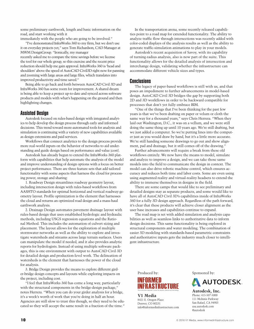
Design documentation was accomplished by importing the IMX file from InfraWorks 360 into AutoCAD Civil 3D. This gives a starting point for detailed design with a surface, an alignment and profile, along with a storm system. The
alignment can be manipulated, and you can add
in vertical curves and horizontal curves as well as the pro-file. The corridor and intersection can also be created from this information.
For visualization, a storyboard is created in InfraWorks 360 to show the client what the potential new subdivision looks like. A 3D video is also output to show the client and sell them on this project.
AutoCAD Civil 3D InfraWorks 360 with AutoCAD Civil 3D
Preliminary Storm Design
With the proposed right-of-way and parcels, the proposed water and sewer are added, using an eight-inch water line and an eight-inch sewer line with manholes. 20 minutesThe existing area is evaluated for stormwater drainage, and a drainage map is created using a new drawing and data referencing the existing surface. The surface is analyzed in a watershed situation, turning on the watershed style. Next, catchment areas are created using the parcels to create drainage areas as well as take the defined catchment areas and turn them into par-cels. Each parcel then is edited for rainfall intensity, time of concentration and coefficient.1 hourLastly, the storm design is tested to make certain the pipes are sized appropriately using Hydraflow.2 hoursTotal: 3 hours, 20 minutes
[Note that in AutoCAD Civil 3D, this work is without any right of way, parcel separation, proposed water and sewer, or a corridor being added to the drawing.]
A storm drainage system is added to the road design. The minimum pipe size is set at 18 inches with five-foot-diameter manholes and two-foot catch basins. 5 minutes
Total time: 7 hours, 35 minutes Total time: 1 hour , 10 minutes
Roadside grading can be applied to the road, which helps determine where buildings can be placed and where the road right of way is located. This is a back-and-forth process with road and building placement to optimize the site.
Complementary ToolsInfraWorks 360 provides many quick and accurate design
abilities along with great 3D graphics, however, it’s not a plan-pro-duction tool. InfraWorks 360 will save time and money in the pre-liminary stage of a project design, but to get that design to a city or county for review, users will need to bring that preliminary design into AutoCAD Civil 3D and create construction documents after massaging the data.
“InfraWorks 360 can and will save clients a minimum of three hours during the initial design process,” says Boutwell. “In some cases, it also saved the client countless dollars with the ability to see the grading and know the volume to be removed from a preliminary site design before a construction document set is cre-ated and submitted to the city. It can save the client from wasting valuable time and resources pursuing an option that isn’t feasible for their budget, before they even get a plan set.”
Our reviewers are all-in on the functionality that InfraWorks 360 added to their project work.
“I see InfraWorks 360 as the analyzing and preliminary design product that can sell a project to a client,” notes Boutwell. “I didn’t take 20 hours to grade out a project, instead I took 10. I got my results a lot faster through InfraWorks 360 than Civil 3D, plus I’m not having to redo it all over again because the client saw it and said it’s not feasible for my pocketbook. It’s an eye opener to a lot of cli-ents when they see it in 3D, and you can bring up things like cut and fill numbers that allow them to compare the cost and say whether it will work or not.”
“Getting all of these pieces of information in InfraWorks 360 would have taken a long time in the past,” adds Herrera. “It’s also great to have all the standards built in. As you’re developing a roadway, you’re developing it per the AASHTO standard or some other standard that you can adjust. You can do the layout, get
© 2016 V1 Media, www.informedinfrastructure.com10
some preliminary earthwork, length and basic information on the road, and start working with it immediately with the people who are going to be involved.”
”I’ve demonstrated InfraWorks 360 to my firm, but we don’t use it on everyday projects yet,” says Tom Richardson, CAD Manager at MWM DesignGroup. “Ironically, my manager recently asked me to compare the time savings before we license the tool for our whole group, so this exercise and the recent price reduction should help me gain approval. InfraWorks 360 is ‘head and shoulders’ above the speed of AutoCAD Civil3D right now for panning and zooming with large areas and large files, which translates into improved productivity and time saved.”
Being able to go back and forth between AutoCAD Civil 3D and InfraWorks 360 has some room for improvement. A shared dream is being able to keep a project up-to-date and synced across software products and models with what’s happening on the ground and then highlighting changes.
Assisted DesignAutodesk focused on rules-based design with integrated analyt-
ics to help develop the design process through early and informed decisions. This trend toward more-automated tools for analysis and simulation is continuing with a variety of new capabilities available as design extensions and paid services.
Workflows that connect analytics to the design process provide more real-world inputs on the behavior of networks to aid under-standing and guide design based on performance and value (cost).
Autodesk has already begun to extend the InfraWorks 360 plat-form with capabilities that help automate the analysis of the model and improve understanding of design options with a focus on better project performance. There are three feature sets that add tailored functionality with some aspects that harness the cloud for process-ing power, storage and sharing:
1. Roadway Design streamlines roadway geometry layout, including intersection design with rules-based workflows from AASHTO standards for optimal horizontal and vertical roadway-ge-ometry layout. Profile optimization is the element that harnesses the cloud and returns an optimized road design and a mass-haul earthwork analysis.
2. Drainage Design automates pavement drainage layout with rules-based design that uses established hydrologic and hydraulic methods, including USGS regression equations and the Ratio-nal Method. This includes the automation of culvert sizing and placement. The layout allows for the exploration of multiple stormwater networks as well as the ability to explore and inves-tigate watersheds and streams across large terrain surfaces. Users can manipulate the model if needed, and it also provides analytic reports for hydrologists. Instead of using multiple software pack-ages, this is one environment with output to AutoCAD Civil 3D for detailed design and production-level work. The delineation of watersheds is the element that harnesses the power of the cloud for analysis.
3. Bridge Design provides the means to explore different gird-er-bridge design concepts and layouts while exploring impacts on the project, including cost.
“I feel that InfraWorks 360 has come a long way, particularly with the structural components in the bridge-design package,” notes Herrera. “When you can do your girder analysis for a bridge, it’s a week’s worth of work that you’re doing in half an hour. Agencies are still slow to trust this though, so they need to be edu-cated so they will accept the same result in a fraction of the time.”
In the transportation arena, some recently released capabili-ties point to a road map for extended functionality. The ability to analyze traffic flow through intersections was recently added with color-coded displays of the analysis results as well as the ability to generate traffic-simulation animations to play in your models.
Autodesk’s recent acquisition of Savoy, with its capability of turning-radius analysis, also is now part of the suite. This functionality allows for the detailed analysis of intersection and interchange design, validating whether the infrastructure can accommodate different vehicle sizes and types.
ConclusionsThe legacy of paper-based workflows is still with us, and that
poses an impediment to further advancements in model-based design. AutoCAD Civil 3D bridges the gap by supporting both 2D and 3D workflows in order to be backward compatible for processes that don’t yet fully embrace BIM.
“One of the things that I’ve been thinking for the past few years is that we’ve been drafting on paper or velum or cloth the same way for a thousand years,” says Chris Herrera. “When they laid out Washington, D.C., it was on a vellum, and we were still doing the same thing up until 10 years ago. We’re still drafting, but we just added a computer. So we’re putting lines into the comput-er just as you would draw by hand, but it’s a little more accurate. We’re still handing someone drawings to go out and show align-ment, pad and drainage, but it still comes off of the drawing.”
Further advancements will require a break from these old workflows entirely. We now have the means to model, simulate and analyze to improve a design, and we can take those same models into the field to communicate the design in context. The model can also drive robotic machine control, which ensures ac-curacy and reduces both time and labor costs. Some are even using using augmented reality and virtual-reality headsets to extend the ability to immerse themselves in designs in the field.
There are some camps that would like to see preliminary and detailed designs stay as separate products, and some would like to have all of AutoCAD Civil 3D’s capabilities inside of InfraWorks 360 for a fully 3D design approach. Regardless of the path forward, it’s clear that these products will achieve closer alignment as the user base increases and capabilities continue to expand.
The road map is set with added simulation and analysis capa-bilities as well as seamless links to authoritative data to inform design decisions. This same functionality is being explored in structural components and water modeling. The combination of easier 3D modeling with standards-based parametric constraints and authoritative inputs gets the industry much closer to intelli-gent infrastructure.
Sponsored by:
Autodesk, Inc.Phone: 415-507-5000111 McInnis ParkwaySan Rafael, CA 94903usa.autodesk.com@autodesk
Produced by:
V1 Media8421 E. Oregon PlaceDenver, CO [email protected]