Embed Size (px)
Citation preview
1
Instruction SheetAdvantage VFD Controller Card
302-064
SUPERSEDES: January 1, 2012 EFFECTIVE: March 1, 2012Plant ID No. 001-4008
Advantage VFD Controller Card

All Rights Reserved. No part of this document may be photo-copied, reproduced, stored in a retrieval system, or transmitted,in any form or by any means whether, electronic, mechanical,or otherwise without the prior written permission of Taco.
No warranty of accuracy is given concerning the contents ofthe information contained in this publication. To the extent per-mitted by law no liability (including liability to any person byreason of negligence) will be accepted by Taco, its subsidiariesor employees for any direct or indirect loss or damage causedby omissions from or inaccuracies in this document.
Taco reserves the right to change details in this publicationwithout notice.
The software described in this manual is sold or licensed “asis”. Should the program prove defective the user assumesthe entire cost of all necessary servicing, repair, and any inci-dental or consequential damages resulting from any defect inthe software. Further, Taco reserves the right to revise thispublication and to make changes from time to time in thecontents hereof without obligation to notify any person ofsuch revision or changes.
2
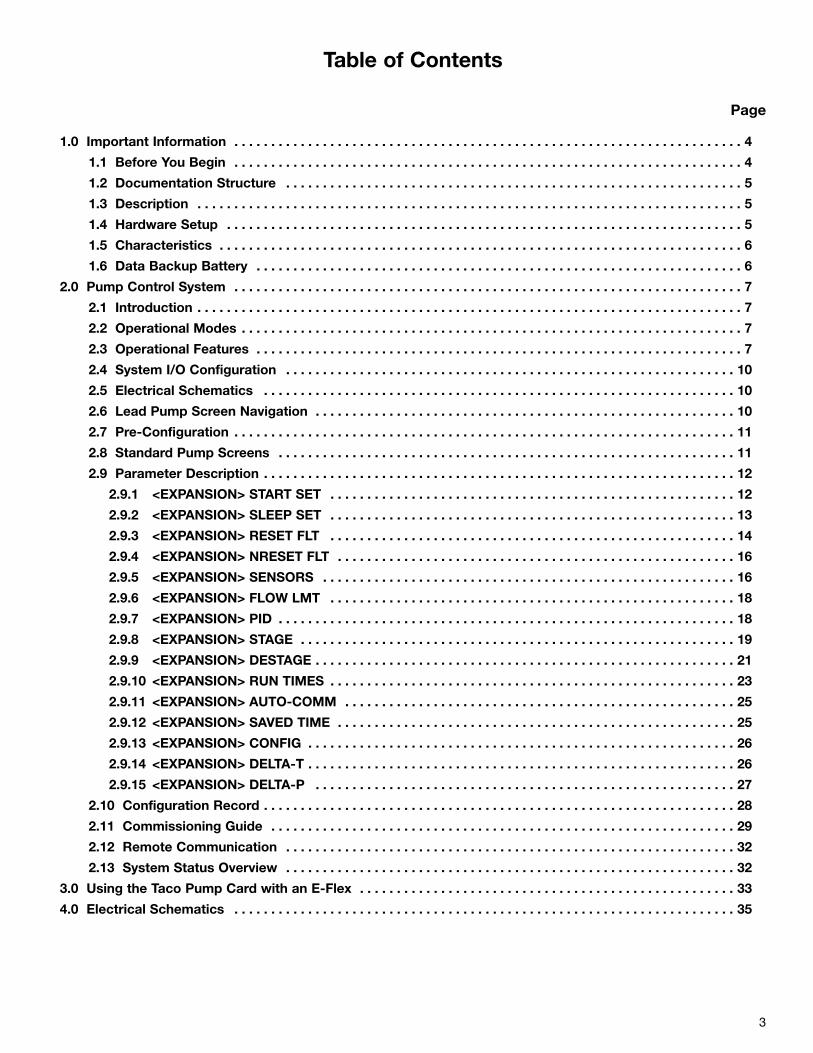
Table of Contents
Page
1.0 Important Information . . . . . . . . . . . . . . . . . . . . . . . . . . . . . . . . . . . . . . . . . . . . . . . . . . . . . . . . . . . . . . . . . . . . . 4
1.1 Before You Begin . . . . . . . . . . . . . . . . . . . . . . . . . . . . . . . . . . . . . . . . . . . . . . . . . . . . . . . . . . . . . . . . . . . . . 4
1.2 Documentation Structure . . . . . . . . . . . . . . . . . . . . . . . . . . . . . . . . . . . . . . . . . . . . . . . . . . . . . . . . . . . . . . 5
1.3 Description . . . . . . . . . . . . . . . . . . . . . . . . . . . . . . . . . . . . . . . . . . . . . . . . . . . . . . . . . . . . . . . . . . . . . . . . . . 5
1.4 Hardware Setup . . . . . . . . . . . . . . . . . . . . . . . . . . . . . . . . . . . . . . . . . . . . . . . . . . . . . . . . . . . . . . . . . . . . . . 5
1.5 Characteristics . . . . . . . . . . . . . . . . . . . . . . . . . . . . . . . . . . . . . . . . . . . . . . . . . . . . . . . . . . . . . . . . . . . . . . . 6
1.6 Data Backup Battery . . . . . . . . . . . . . . . . . . . . . . . . . . . . . . . . . . . . . . . . . . . . . . . . . . . . . . . . . . . . . . . . . . 6
2.0 Pump Control System . . . . . . . . . . . . . . . . . . . . . . . . . . . . . . . . . . . . . . . . . . . . . . . . . . . . . . . . . . . . . . . . . . . . . 7
2.1 Introduction . . . . . . . . . . . . . . . . . . . . . . . . . . . . . . . . . . . . . . . . . . . . . . . . . . . . . . . . . . . . . . . . . . . . . . . . . . 7
2.2 Operational Modes . . . . . . . . . . . . . . . . . . . . . . . . . . . . . . . . . . . . . . . . . . . . . . . . . . . . . . . . . . . . . . . . . . . . 7
2.3 Operational Features . . . . . . . . . . . . . . . . . . . . . . . . . . . . . . . . . . . . . . . . . . . . . . . . . . . . . . . . . . . . . . . . . . 7
2.4 System I/O Configuration . . . . . . . . . . . . . . . . . . . . . . . . . . . . . . . . . . . . . . . . . . . . . . . . . . . . . . . . . . . . . 10
2.5 Electrical Schematics . . . . . . . . . . . . . . . . . . . . . . . . . . . . . . . . . . . . . . . . . . . . . . . . . . . . . . . . . . . . . . . . 10
2.6 Lead Pump Screen Navigation . . . . . . . . . . . . . . . . . . . . . . . . . . . . . . . . . . . . . . . . . . . . . . . . . . . . . . . . . 10
2.7 Pre-Configuration . . . . . . . . . . . . . . . . . . . . . . . . . . . . . . . . . . . . . . . . . . . . . . . . . . . . . . . . . . . . . . . . . . . . 11
2.8 Standard Pump Screens . . . . . . . . . . . . . . . . . . . . . . . . . . . . . . . . . . . . . . . . . . . . . . . . . . . . . . . . . . . . . . 11
2.9 Parameter Description . . . . . . . . . . . . . . . . . . . . . . . . . . . . . . . . . . . . . . . . . . . . . . . . . . . . . . . . . . . . . . . . 12
2.9.1 <EXPANSION> START SET . . . . . . . . . . . . . . . . . . . . . . . . . . . . . . . . . . . . . . . . . . . . . . . . . . . . . . . 12
2.9.2 <EXPANSION> SLEEP SET . . . . . . . . . . . . . . . . . . . . . . . . . . . . . . . . . . . . . . . . . . . . . . . . . . . . . . . 13
2.9.3 <EXPANSION> RESET FLT . . . . . . . . . . . . . . . . . . . . . . . . . . . . . . . . . . . . . . . . . . . . . . . . . . . . . . . 14
2.9.4 <EXPANSION> NRESET FLT . . . . . . . . . . . . . . . . . . . . . . . . . . . . . . . . . . . . . . . . . . . . . . . . . . . . . . 16
2.9.5 <EXPANSION> SENSORS . . . . . . . . . . . . . . . . . . . . . . . . . . . . . . . . . . . . . . . . . . . . . . . . . . . . . . . . 16
2.9.6 <EXPANSION> FLOW LMT . . . . . . . . . . . . . . . . . . . . . . . . . . . . . . . . . . . . . . . . . . . . . . . . . . . . . . . 18
2.9.7 <EXPANSION> PID . . . . . . . . . . . . . . . . . . . . . . . . . . . . . . . . . . . . . . . . . . . . . . . . . . . . . . . . . . . . . . 18
2.9.8 <EXPANSION> STAGE . . . . . . . . . . . . . . . . . . . . . . . . . . . . . . . . . . . . . . . . . . . . . . . . . . . . . . . . . . . 19
2.9.9 <EXPANSION> DESTAGE . . . . . . . . . . . . . . . . . . . . . . . . . . . . . . . . . . . . . . . . . . . . . . . . . . . . . . . . . 21
2.9.10 <EXPANSION> RUN TIMES . . . . . . . . . . . . . . . . . . . . . . . . . . . . . . . . . . . . . . . . . . . . . . . . . . . . . . . 23
2.9.11 <EXPANSION> AUTO-COMM . . . . . . . . . . . . . . . . . . . . . . . . . . . . . . . . . . . . . . . . . . . . . . . . . . . . . 25
2.9.12 <EXPANSION> SAVED TIME . . . . . . . . . . . . . . . . . . . . . . . . . . . . . . . . . . . . . . . . . . . . . . . . . . . . . . 25
2.9.13 <EXPANSION> CONFIG . . . . . . . . . . . . . . . . . . . . . . . . . . . . . . . . . . . . . . . . . . . . . . . . . . . . . . . . . . 26
2.9.14 <EXPANSION> DELTA-T . . . . . . . . . . . . . . . . . . . . . . . . . . . . . . . . . . . . . . . . . . . . . . . . . . . . . . . . . . 26
2.9.15 <EXPANSION> DELTA-P . . . . . . . . . . . . . . . . . . . . . . . . . . . . . . . . . . . . . . . . . . . . . . . . . . . . . . . . . 27
2.10 Configuration Record . . . . . . . . . . . . . . . . . . . . . . . . . . . . . . . . . . . . . . . . . . . . . . . . . . . . . . . . . . . . . . . . 28
2.11 Commissioning Guide . . . . . . . . . . . . . . . . . . . . . . . . . . . . . . . . . . . . . . . . . . . . . . . . . . . . . . . . . . . . . . . 29
2.12 Remote Communication . . . . . . . . . . . . . . . . . . . . . . . . . . . . . . . . . . . . . . . . . . . . . . . . . . . . . . . . . . . . . 32
2.13 System Status Overview . . . . . . . . . . . . . . . . . . . . . . . . . . . . . . . . . . . . . . . . . . . . . . . . . . . . . . . . . . . . . 32
3.0 Using the Taco Pump Card with an E-Flex . . . . . . . . . . . . . . . . . . . . . . . . . . . . . . . . . . . . . . . . . . . . . . . . . . . 33
4.0 Electrical Schematics . . . . . . . . . . . . . . . . . . . . . . . . . . . . . . . . . . . . . . . . . . . . . . . . . . . . . . . . . . . . . . . . . . . . 35
3
NOTICERead these instructions carefully, and look at the equipmentto become familiar with the device before trying to install,operate, or maintain it. The following special messages mayappear throughout this documentation or on the equipmentto warn of potential hazards or to call attention to informationthat clarifies or simplifies a procedure.
The addition of this symbol to a Danger or Warningsafety label indicates that an electrical hazard exists,which will result in personal injury if the instructions
are not followed.
This is the safety alert symbol. It is used to alert youto potential personal injury hazards. Obey all safetymessages that follow this symbol to avoid possible
injury or death.
PLEASE NOTEElectrical equipment should be serviced only by qualifiedpersonnel. No responsibility is assumed by Taco for any con-sequence arising out of the use of this material. This docu-ment is not intended as an instruction manual for untrainedpersons.© 2011 Taco, Inc. All Rights Reserved.
1.1 Before You BeginRead and understand these instructions before performingany procedure on this drive.
4
DANGERDANGER indicates an imminently hazardous situationwhich, if not avoided, will result in death, serious injuryor equipment damage.
WARNING indicates a potentially hazardous situationwhich, if not avoided, can result in death, serious injuryor equipment damage.
WARNING
CAUTION indicates a potentially hazardous situationwhich, if not avoided, can result in injury or equipmentdamage.
CAUTION
DANGER
HAZARDOUS VOLTAGE
• Read and understand the installation manual beforeinstalling or operating the Altivar 61 drive. Installation,adjustment, repair and maintenance must be per-formed by qualified personnel.
• The user is responsible for compliance with all interna-tional and national electrical standards in force con-cerning protective grounding of all equipment.
• Many parts of this variable speed drive, including theprinted circuit boards, operate at the line voltage. DONOT TOUCH. Use only electrically insulated tools.
• DO NOT touch unshielded components or terminalstrip screw connections with voltage present.
• DO NOT short across terminals PA and PC or acrossthe DC bus capacitors.
• Install and close all the covers before applying poweror starting and stopping the drive.
• Before servicing the variable speed drive:
- Disconnect all power.- Place a DO NOT TURN ON label on the variable speed drive disconnect.
- Lock the disconnect in the open position.
• Disconnect all power including external control powerthat may be present before servicing the drive. WAIT 15MINUTES to allow the DC bus capacitors to discharge.Then follow the DC bus voltage measurement proce-dure given in the installation manual to verify that theDC voltage is less than 45 VDC. The drive LEDs are notaccurate indicators of the absence of DC bus voltage.
Failure to follow these instructions will result in deathor serious injury.
DAMAGED EQUIPMENT
• Do not install or operate any drive that appears dam-aged.
Failure to follow this instruction can result in equip-ment damage.
CAUTION
1.0 IMPORTANT INFORMATION
1.2 Documentation StructureInstallation manual
This manual describes:• Assembly• How to connect the drive
Programming manual
This manual describes:• The functions• The parameters• How to use the drive display terminal (integrated
display terminal and graphic display terminal)
Communication parameters manual
This manual describes:• The drive parameters with specific information
(addresses, formats, etc) for use via a bus orcommunication network
• The operating modes specific to communication (state chart)
• The interaction between communication and local control
Modbus, BacNET, Apogee FLN P1 manual,DeviceNet, Metasys N2
These manuals describe:• Connection to the bus or network• Configuration of the communication-specific
parameters via the integrated display terminalor the graphic display terminal
• Diagnostics• Software setup• The communication services specific to the protocol
Advantage VFD Controller Card manual
This manual describes:• Commissioning and functionality of
controller system
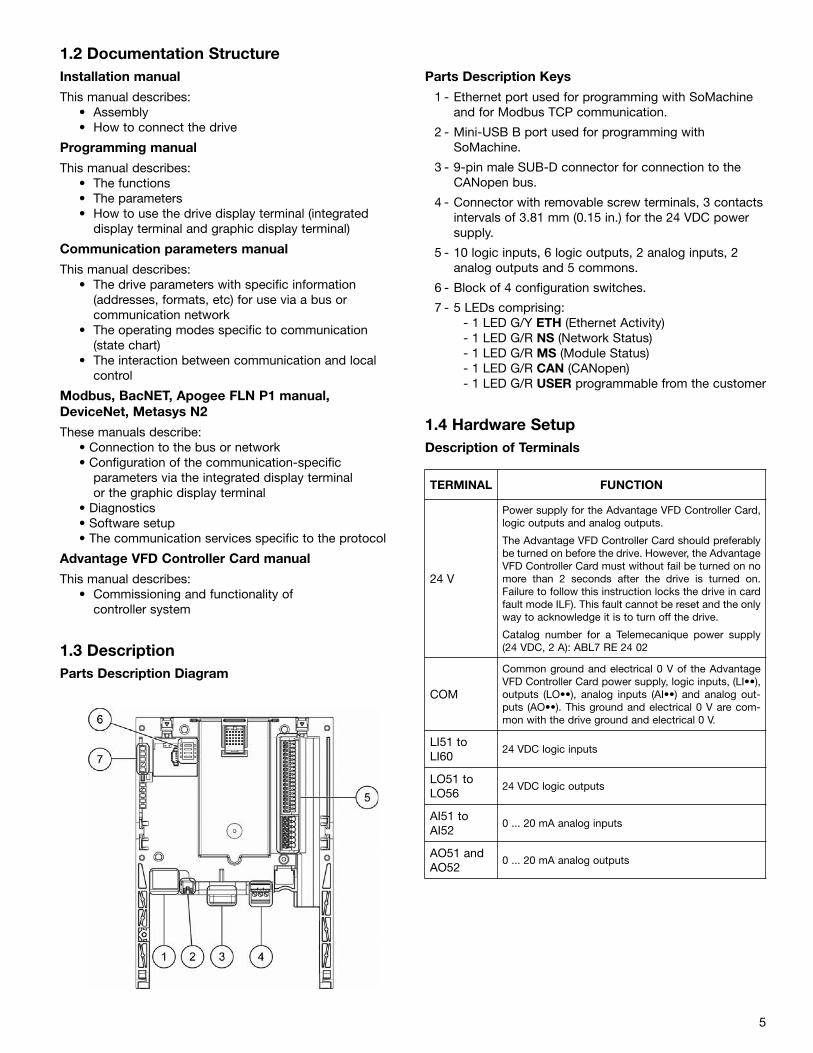
1.3 DescriptionParts Description Diagram
Parts Description Keys
1 - Ethernet port used for programming with SoMachine and for Modbus TCP communication.
2 - Mini-USB B port used for programming with SoMachine.
3 - 9-pin male SUB-D connector for connection to the CANopen bus.
4 - Connector with removable screw terminals, 3 contactsintervals of 3.81 mm (0.15 in.) for the 24 VDC power supply.
5 - 10 logic inputs, 6 logic outputs, 2 analog inputs, 2 analog outputs and 5 commons.
6 - Block of 4 configuration switches.
7 - 5 LEDs comprising:- 1 LED G/Y ETH (Ethernet Activity)- 1 LED G/R NS (Network Status)- 1 LED G/R MS (Module Status)- 1 LED G/R CAN (CANopen)- 1 LED G/R USER programmable from the customer
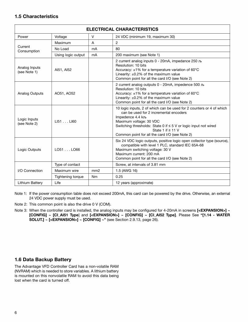
1.4 Hardware SetupDescription of Terminals
5
TERMINAL FUNCTION
24 V
Power supply for the Advantage VFD Controller Card,logic outputs and analog outputs.
The Advantage VFD Controller Card should preferablybe turned on before the drive. However, the AdvantageVFD Controller Card must without fail be turned on nomore than 2 seconds after the drive is turned on.Failure to follow this instruction locks the drive in cardfault mode ILF). This fault cannot be reset and the onlyway to acknowledge it is to turn off the drive.
Catalog number for a Telemecanique power supply(24 VDC, 2 A): ABL7 RE 24 02
COM
Common ground and electrical 0 V of the AdvantageVFD Controller Card power supply, logic inputs, (LI••),outputs (LO••), analog inputs (AI••) and analog out-puts (AO••). This ground and electrical 0 V are com-mon with the drive ground and electrical 0 V.
LI51 toLI60
24 VDC logic inputs
LO51 toLO56
24 VDC logic outputs
AI51 toAI52
0 ... 20 mA analog inputs
AO51 andAO52
0 ... 20 mA analog outputs
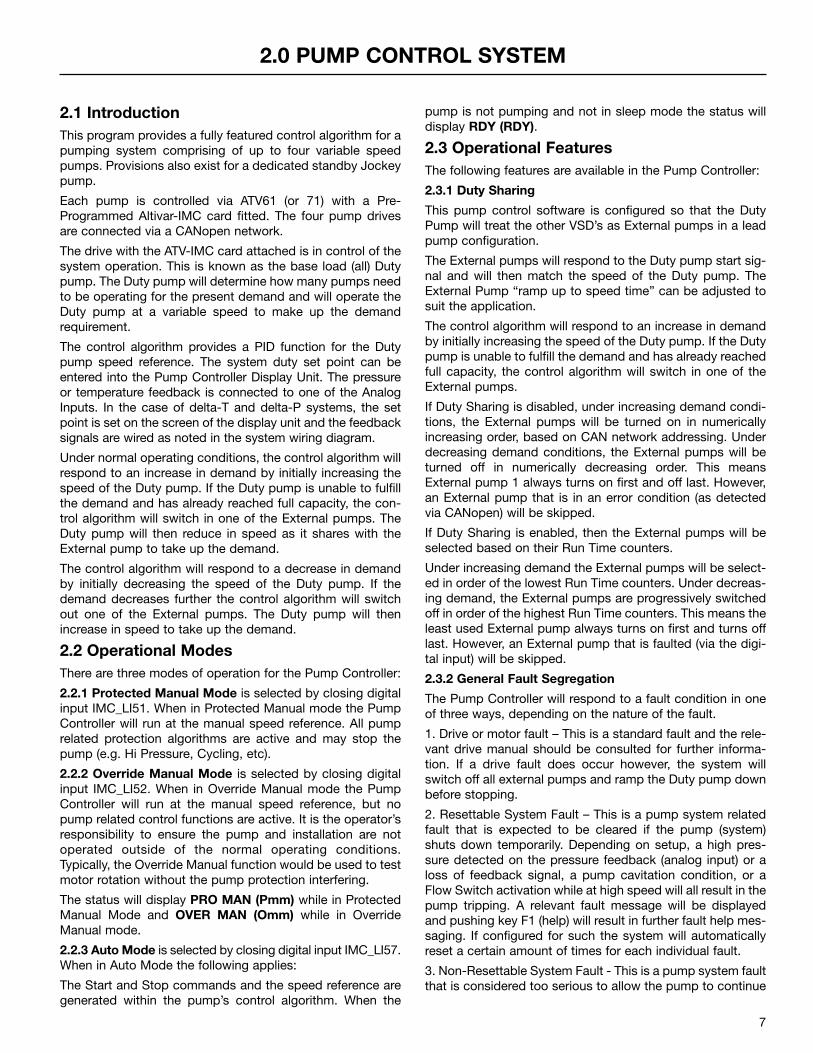
1.5 Characteristics
6
1.6 Data Backup BatteryThe Advantage VFD Controller Card has a non-volatile RAM(NVRAM) which is needed to store variables. A lithium batteryis mounted on this nonvolatile RAM to avoid this data beinglost when the card is turned off.
ELECTRICAL CHARACTERISTICS
Power Voltage V 24 VDC (minimum 19, maximum 30)
CurrentConsumption
Maximum A 2
No Load mA 80
Using logic output mA 200 maximum (see Note 1)
Analog Inputs(see Note 1)
AI51, AI52
2 current analog inputs 0 - 20mA, impedance 250 љResolution: 10 bitsAccuracy: ±1% for a temperature variation of 60°CLinearity: ±0.2% of the maximum valueCommon point for all the card I/O (see Note 2)
Analog Outputs AO51, AO52
2 current analog outputs 0 - 20mA, impedence 500 љResolution: 10 bitsAccuracy: ±1% for a temperature variation of 60°CLinearity: ±0.2% of the maximum valueCommon point for all the card I/O (see Note 2)
Logic Inputs(see Note 2)
LI51 . . . LI60
10 logic inputs, 2 of which can be used for 2 counters or 4 of whichcan be used for 2 incremental encoders
Impedence 4.4 kљ
Maximum voltage: 30 VDCSwitching thresholds: State 0 if ≤ 5 V or logic input not wired
State 1 if ≥ 11 VCommon point for all the card I/O (see Note 2)
Logic Outputs LO51 . . . LO66
Six 24 VDC logic outputs, positive logic open collector type (source),compatible with level 1 PLC, standard IEC 65A-68
Maximum switching voltage: 30 VMaximum current: 200 mACommon point for all the card I/O (see Note 2)
I/O Connection
Type of contact Screw, at intervals of 3.81 mm
Maximum wire mm2 1.5 (AWG 16)
Tightening torque Nm 0.25
Lithium Battery Life 12 years (approximate)
Note 1: If the power consumption table does not exceed 200mA, this card can be powered by the drive. Otherwise, an external24 VDC power supply must be used.
Note 2: This common point is also the drive 0 V (COM).
Note 3: When the controller card is installed, the analog inputs may be configured for 4-20mA in screens [<EXPANSION>] ~[CONFIG] ~ [CI_AI51 Type] and [<EXPANSION>] ~ [CONFIG] ~ [CI_AI52 Type]. Please See “[1.14 - WATERSOLUT.] ~ [<EXPANSION>] ~ [CONFIG] ~” (see Section 2.9.13, page 26).
2.1 IntroductionThis program provides a fully featured control algorithm for apumping system comprising of up to four variable speedpumps. Provisions also exist for a dedicated standby Jockeypump.
Each pump is controlled via ATV61 (or 71) with a Pre-Programmed Altivar-IMC card fitted. The four pump drivesare connected via a CANopen network.
The drive with the ATV-IMC card attached is in control of thesystem operation. This is known as the base load (all) Dutypump. The Duty pump will determine how many pumps needto be operating for the present demand and will operate theDuty pump at a variable speed to make up the demandrequirement.
The control algorithm provides a PID function for the Dutypump speed reference. The system duty set point can beentered into the Pump Controller Display Unit. The pressureor temperature feedback is connected to one of the AnalogInputs. In the case of delta-T and delta-P systems, the setpoint is set on the screen of the display unit and the feedbacksignals are wired as noted in the system wiring diagram.
Under normal operating conditions, the control algorithm willrespond to an increase in demand by initially increasing thespeed of the Duty pump. If the Duty pump is unable to fulfillthe demand and has already reached full capacity, the con-trol algorithm will switch in one of the External pumps. TheDuty pump will then reduce in speed as it shares with theExternal pump to take up the demand.
The control algorithm will respond to a decrease in demandby initially decreasing the speed of the Duty pump. If thedemand decreases further the control algorithm will switchout one of the External pumps. The Duty pump will thenincrease in speed to take up the demand.
2.2 Operational ModesThere are three modes of operation for the Pump Controller:
2.2.1 Protected Manual Mode is selected by closing digitalinput IMC_LI51. When in Protected Manual mode the PumpController will run at the manual speed reference. All pumprelated protection algorithms are active and may stop thepump (e.g. Hi Pressure, Cycling, etc).
2.2.2 Override Manual Mode is selected by closing digitalinput IMC_LI52. When in Override Manual mode the PumpController will run at the manual speed reference, but nopump related control functions are active. It is the operator’sresponsibility to ensure the pump and installation are notoperated outside of the normal operating conditions.Typically, the Override Manual function would be used to testmotor rotation without the pump protection interfering.
The status will display PRO MAN (Pmm) while in ProtectedManual Mode and OVER MAN (Omm) while in OverrideManual mode.
2.2.3 Auto Mode is selected by closing digital input IMC_LI57.When in Auto Mode the following applies:
The Start and Stop commands and the speed reference aregenerated within the pump’s control algorithm. When the
pump is not pumping and not in sleep mode the status willdisplay RDY (RDY).
2.3 Operational FeaturesThe following features are available in the Pump Controller:
2.3.1 Duty Sharing
This pump control software is configured so that the DutyPump will treat the other VSD’s as External pumps in a leadpump configuration.
The External pumps will respond to the Duty pump start sig-nal and will then match the speed of the Duty pump. TheExternal Pump “ramp up to speed time” can be adjusted tosuit the application.
The control algorithm will respond to an increase in demandby initially increasing the speed of the Duty pump. If the Dutypump is unable to fulfill the demand and has already reachedfull capacity, the control algorithm will switch in one of theExternal pumps.
If Duty Sharing is disabled, under increasing demand condi-tions, the External pumps will be turned on in numericallyincreasing order, based on CAN network addressing. Underdecreasing demand conditions, the External pumps will beturned off in numerically decreasing order. This meansExternal pump 1 always turns on first and off last. However,an External pump that is in an error condition (as detectedvia CANopen) will be skipped.
If Duty Sharing is enabled, then the External pumps will beselected based on their Run Time counters.
Under increasing demand the External pumps will be select-ed in order of the lowest Run Time counters. Under decreas-ing demand, the External pumps are progressively switchedoff in order of the highest Run Time counters. This means theleast used External pump always turns on first and turns offlast. However, an External pump that is faulted (via the digi-tal input) will be skipped.
2.3.2 General Fault Segregation
The Pump Controller will respond to a fault condition in oneof three ways, depending on the nature of the fault.
1. Drive or motor fault – This is a standard fault and the rele-vant drive manual should be consulted for further informa-tion. If a drive fault does occur however, the system willswitch off all external pumps and ramp the Duty pump downbefore stopping.
2. Resettable System Fault – This is a pump system relatedfault that is expected to be cleared if the pump (system)shuts down temporarily. Depending on setup, a high pres-sure detected on the pressure feedback (analog input) or aloss of feedback signal, a pump cavitation condition, or aFlow Switch activation while at high speed will all result in thepump tripping. A relevant fault message will be displayedand pushing key F1 (help) will result in further fault help mes-saging. If configured for such the system will automaticallyreset a certain amount of times for each individual fault.
3. Non-Resettable System Fault - This is a pump system faultthat is considered too serious to allow the pump to continue
7
2.0 PUMP CONTROL SYSTEM
operating. Cycling of the pump (starting too often), activationof the Low Water digital input, or the minimum pressuredetection will all result in the pump (system) tripping andremaining off until reset. A relevant fault message will be dis-played and pushing key F1 (help) will result in further faulthelp messaging.
2.3.3 Signal Loss Detection (Fault Tolerant Control)
If a loss of a feedback signal is detected, the system willautomatically revert to a preset speed of 3⁄4 of the high speedsetting. Loss of signal is characterised by a 0 V or 0mA feed-back value and applies to delta-T, delta-P and pressure feed-back signals and does not apply to flow feedback signals.The function remains active as long as the system is in runmode.
2.3.4 External Pump Control – increasing demand (staging)
The Duty pump will respond to an increase in demand by ini-tially increasing speed. If the demand is too great for the Dutypump to fulfill, the Duty pump will start an External pump.
A high demand condition can be detected by either:
• High Duty pump speed• High Duty pump speed + delay• Increasing system error (system error = setpoint –
feedback)• Increasing system error + delay• High Duty pump speed and increasing system error• High Duty pump speed and increasing system error +
delay
This allows the response mode to be setup to suit the sys-tem requirements. By default, the “system error + delay”method is used to make a stage/destage decision.
2.3.5 External Pump Control – decreasing demand(destaging)
The Lead pump will respond to a decrease in demand by ini-tially decreasing speed. If the demand is too low for the num-ber of pumps running, the Lead pump will stop an Externalpump.
A low demand condition can be detected by either:
• Low Lead pump speed• Low Lead pump speed + delay• Decreasing (or negative) system error (over pressure)• Decreasing system error + delay• Low Lead pump speed and decreasing system error• Low Lead pump speed and decreasing system error
+ delay
This allows the response mode to be setup to suit the sys-tem requirements.
In some instances, a decreasing demand condition may berequired to turn the Lead pump off while one or moreExternal Speed pumps are still running. Due to the flexibilityof the Lead pump system, it is possible to configure the Leadpump to turn off due to the No Demand permissive while theExternal pumps continue to run.
2.3.6 No Demand Operation
During a period of decreasing demand, the control algorithmwill turn off the External pumps and the Lead pump speedwill decrease. When a No Demand condition is detected, theLead pump will continue running but revert to the low speedas set up by the user.
A no demand condition can be detected by any combinationof:
• Low Lead pump speed• Low Lead pump current• Low flow rate (flow meter)• Low flow rate (flow switch)
2.3.7 PID Bypass Speeds
During pump switching, better performance may beachieved if the PID is bypassed, rather than relying on thePID response alone to adjust the pump speed to accommo-date for the increased or decreased flow capacity. There aretwo bypass speeds available.
1. Stage Bypass – When the Lead pump requests anExternal pump to start, the Stage Bypass Speed is used todecrease the Lead pump speed to accommodate for theincreased flow capacity of the additional pump.
2. Destage Bypass – When the Lead pump requests anExternal pump to stop, the Destage Bypass Speed is used toincrease the Lead pump speed to accommodate for thedecreased flow capacity.
The Lead pump’s status will display BYP while any of theBypass speeds are active.
2.3.8 Setpoint Ramp
On initial starting or after a period of no demand, the feed-back pressure may be below the setpoint pressure. To avoidthe effects of the resultant feedback error on the PID, theSetpoint Ramp algorithm overrides the pressure setpoint andapplies a derived setpoint to the PID controller. The derivedsetpoint commences at the present feedback pressure(resulting in no error being applied to the PID controller) andramps up to the desired setpoint. The rate at which the set-point ramp occurs is adjustable.
The setpoint ramp is considered complete if the system errorreduces to 0, (system error = setpoint - feedback) i.e. thesystem has successfully started and the feedback pressurehas risen to the setpoint pressure.
The Lead pump’s status screen will indicate RAMP during aSetpoint Ramp.
2.3.9 Pulse Flow Meter Input
The Pump Controller will accept direct connection from apulse emitter type flow meter. This pulse signal is directlyconverted into a flow rate within the Pump Control software.
The pump Controller will also accept a flow signal via theanalog inputs if required.
2.3.10 Flow Limiting
When the flow must be restricted to a particular level, theFlow Limit algorithm may be used. If the flow reaches theFlow Limit, the motor speed is ramped down. Once the flowis below the Flow Limit, the motor speed is held at its pres-ent value (or allowed to decrease if required). The Flow Limitalgorithm will release the motor speed once the flow hasdropped below the Flow Limit Reset. The rate at which themotor speed is ramped down is adjustable.
While the Flow Limit is active, the status will display QLT.
2.3.11 Pipe Fill
On initial start up, it is possible that there is minimal or nofluid in the downstream pipe. To avoid the effects of the
8
resultant feedback error on the PID, the Pipe Fill algorithmmay override the PID when the Lead pump starts. The Leadpump will run at a preset speed until the system pressureincreases to indicate the presence of fluid in the pipe.
The Lead pump’s status will display FILL while the Pipe Fill isactive.
2.3.12 Multiple Acceleration and Deceleration Rates
The system uses different rates depending on status. Onerate of acceleration and one of deceleration can be config-ured for times when the speed is below minimum (LSP). Thisis used to meet pump manufacturer specifications for pumpsthat require a minimum speed for pump cooling. There arealso rates used when the system is under PID control thatallows optimum performance. A third deceleration rate isused when the flow limit algorithm is active and a fourthwhen a fault condition is present.
2.3.13 Automatic Turn-On Turn-Off (Set Time Pumping)
The pump system can be configured to run automaticallybased on time. The system can be allowed to start at a userspecified time and also turn off at a user specified time. Thisallows for such things as nighttime irrigation.
2.3.14 Pressure Display in Engineering Units
The pressure feedback signal can be displayed as a percent-age value, or in the following engineering units:
• psi• ft.hd• m.hd• Bar• kPa
2.3.15 System Shutdown Options
The lead pump stop type can be selected as either rampstop or free wheel stop. If a fault condition is present andramp stop is chosen the system will ramp down at the rateset as the fault ramp and then trip displaying the relevantfault message. If the fault is Resettable the system mayrestart after a time delay if so configured.
When the Lead pump turns off under No Demand conditions,the destage mode selected will determine the response ofthe External pumps at this time. If the Lead pump speed is acondition of destaging, then the External pumps will sequen-tially shutdown at intervals of the destage delay. If the Leadpump speed is not a requirement for destaging, the Externalpumps will remain running until a decreasing demand caus-es an over-pressure condition.
2.3.16 Minimum Pressure (High Flow) Protection
If enabled the system will trip if a minimum pressure can’t bemet when the lead pump is running at a speed greater thanthat set. If minimum pressure (possible burst pipe) is sensed,the system will stop and trip displaying MIN PRESS. Thisfault will not auto reset.
2.3.17 Cavitation Protection
The Lead pump has a Cavitation protection algorithm.Cavitation is detected by high pump speed and low motorcurrent. When cavitation is detected, the system will stopand trip displaying CAVITATION. If so configured the systemwill auto reset.
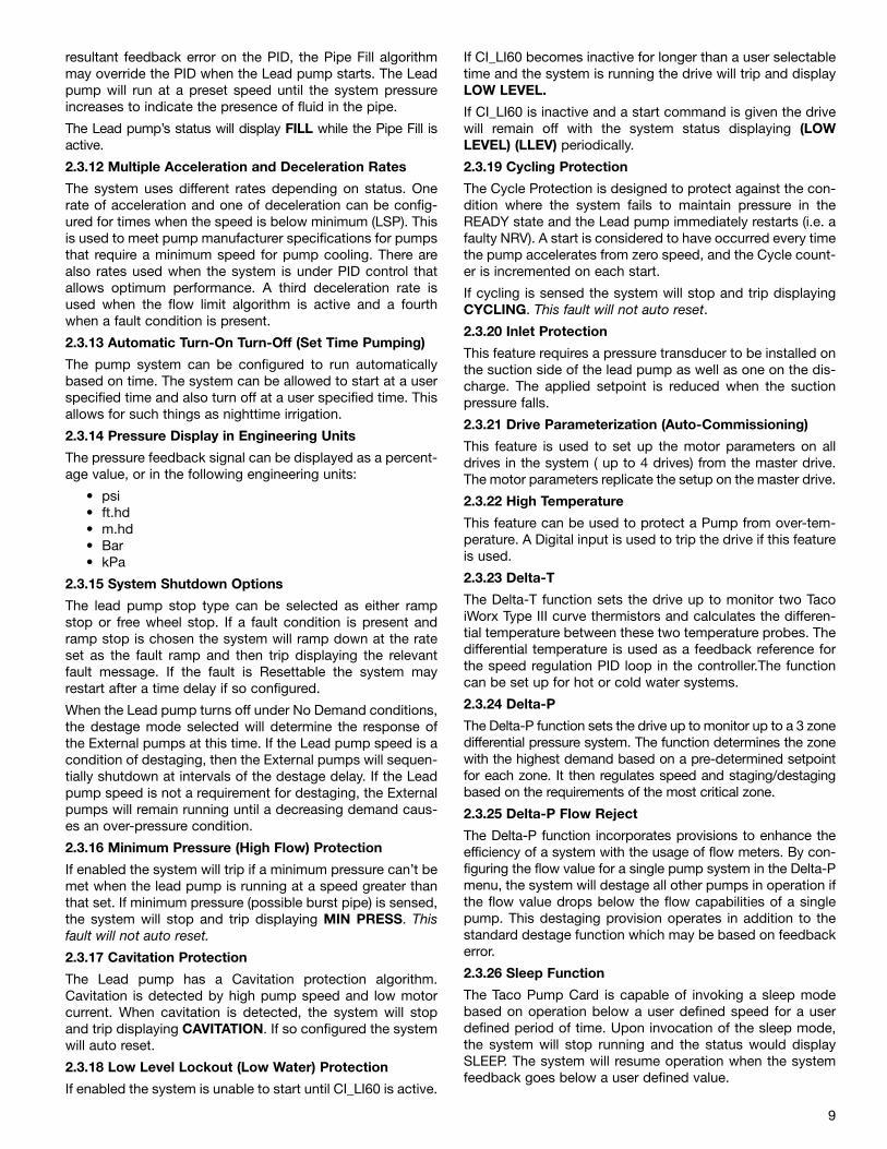
2.3.18 Low Level Lockout (Low Water) Protection
If enabled the system is unable to start until CI_LI60 is active.
If CI_LI60 becomes inactive for longer than a user selectabletime and the system is running the drive will trip and displayLOW LEVEL.
If CI_LI60 is inactive and a start command is given the drivewill remain off with the system status displaying (LOWLEVEL) (LLEV) periodically.
2.3.19 Cycling Protection
The Cycle Protection is designed to protect against the con-dition where the system fails to maintain pressure in theREADY state and the Lead pump immediately restarts (i.e. afaulty NRV). A start is considered to have occurred every timethe pump accelerates from zero speed, and the Cycle count-er is incremented on each start.
If cycling is sensed the system will stop and trip displayingCYCLING. This fault will not auto reset.
2.3.20 Inlet Protection
This feature requires a pressure transducer to be installed onthe suction side of the lead pump as well as one on the dis-charge. The applied setpoint is reduced when the suctionpressure falls.
2.3.21 Drive Parameterization (Auto-Commissioning)
This feature is used to set up the motor parameters on alldrives in the system ( up to 4 drives) from the master drive.The motor parameters replicate the setup on the master drive.
2.3.22 High Temperature
This feature can be used to protect a Pump from over-tem-perature. A Digital input is used to trip the drive if this featureis used.
2.3.23 Delta-T
The Delta-T function sets the drive up to monitor two TacoiWorx Type III curve thermistors and calculates the differen-tial temperature between these two temperature probes. Thedifferential temperature is used as a feedback reference forthe speed regulation PID loop in the controller.The functioncan be set up for hot or cold water systems.
2.3.24 Delta-P
The Delta-P function sets the drive up to monitor up to a 3 zonedifferential pressure system. The function determines the zonewith the highest demand based on a pre-determined setpointfor each zone. It then regulates speed and staging/destagingbased on the requirements of the most critical zone.
2.3.25 Delta-P Flow Reject
The Delta-P function incorporates provisions to enhance theefficiency of a system with the usage of flow meters. By con-figuring the flow value for a single pump system in the Delta-Pmenu, the system will destage all other pumps in operation ifthe flow value drops below the flow capabilities of a singlepump. This destaging provision operates in addition to thestandard destage function which may be based on feedbackerror.
2.3.26 Sleep Function
The Taco Pump Card is capable of invoking a sleep modebased on operation below a user defined speed for a userdefined period of time. Upon invocation of the sleep mode,the system will stop running and the status would displaySLEEP. The system will resume operation when the systemfeedback goes below a user defined value.
9
By default, the system sleep setpoint is automatically set tothe low speed of the drive and as such the sleep function isnot activated.
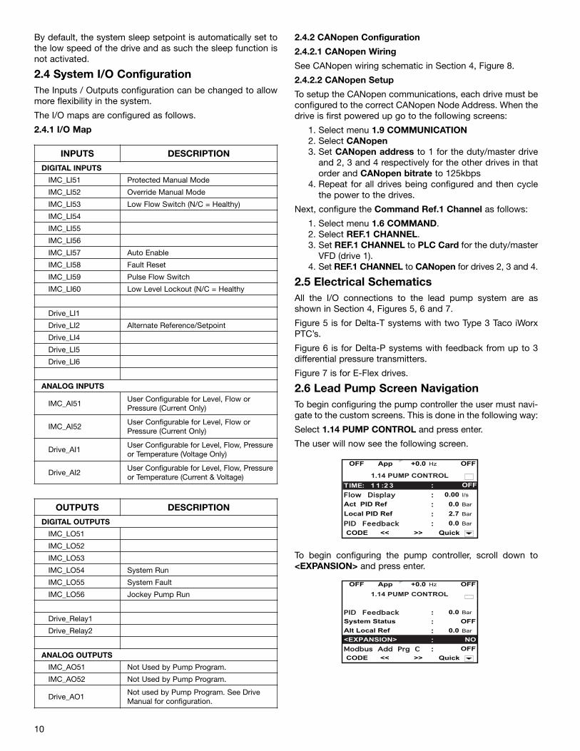
2.4 System I/O ConfigurationThe Inputs / Outputs configuration can be changed to allowmore flexibility in the system.
The I/O maps are configured as follows.
2.4.1 I/O Map
2.4.2 CANopen Configuration
2.4.2.1 CANopen Wiring
See CANopen wiring schematic in Section 4, Figure 8.
2.4.2.2 CANopen Setup
To setup the CANopen communications, each drive must beconfigured to the correct CANopen Node Address. When thedrive is first powered up go to the following screens:
1. Select menu 1.9 COMMUNICATION2. Select CANopen3. Set CANopen address to 1 for the duty/master drive
and 2, 3 and 4 respectively for the other drives in thatorder and CANopen bitrate to 125kbps
4. Repeat for all drives being configured and then cyclethe power to the drives.
Next, configure the Command Ref.1 Channel as follows:
1. Select menu 1.6 COMMAND.2. Select REF.1 CHANNEL.3. Set REF.1 CHANNEL to PLC Card for the duty/master
VFD (drive 1).4. Set REF.1 CHANNEL to CANopen for drives 2, 3 and 4.
2.5 Electrical SchematicsAll the I/O connections to the lead pump system are asshown in Section 4, Figures 5, 6 and 7.
Figure 5 is for Delta-T systems with two Type 3 Taco iWorxPTC’s.
Figure 6 is for Delta-P systems with feedback from up to 3differential pressure transmitters.
Figure 7 is for E-Flex drives.
2.6 Lead Pump Screen NavigationTo begin configuring the pump controller the user must navi-gate to the custom screens. This is done in the following way:
Select 1.14 PUMP CONTROL and press enter.
The user will now see the following screen.
To begin configuring the pump controller, scroll down to<EXPANSION> and press enter.
10
INPUTS DESCRIPTION
DIGITAL INPUTS
IMC_LI51 Protected Manual Mode
IMC_LI52 Override Manual Mode
IMC_LI53 Low Flow Switch (N/C = Healthy)
IMC_LI54
IMC_LI55
IMC_LI56
IMC_LI57 Auto Enable
IMC_LI58 Fault Reset
IMC_LI59 Pulse Flow Switch
IMC_LI60 Low Level Lockout (N/C = Healthy
Drive_LI1
Drive_LI2 Alternate Reference/Setpoint
Drive_LI4
Drive_LI5
Drive_LI6
ANALOG INPUTS
IMC_AI51User Configurable for Level, Flow orPressure (Current Only)
IMC_AI52User Configurable for Level, Flow orPressure (Current Only)
Drive_AI1User Configurable for Level, Flow, Pressureor Temperature (Voltage Only)
Drive_AI2User Configurable for Level, Flow, Pressureor Temperature (Current & Voltage)
OUTPUTS DESCRIPTION
DIGITAL OUTPUTS
IMC_LO51
IMC_LO52
IMC_LO53
IMC_LO54 System Run
IMC_LO55 System Fault
IMC_LO56 Jockey Pump Run
Drive_Relay1
Drive_Relay2
ANALOG OUTPUTS
IMC_AO51 Not Used by Pump Program.
IMC_AO52 Not Used by Pump Program.
Drive_AO1Not used by Pump Program. See DriveManual for configuration.
OFF App +0.0 Hz OFF
:: OFF
:: 0.00 I/s
:: 0.0 Bar
Local PID Ref :: 2.7 Bar
:: 0.0 Bar
CODE << Quick
PPIIDD FFeeeeddbbaacckk>>
TTIIMMEE:: 11 11 ::22 33
FFllooww DDiissppllaayyAct PID Ref
1.14 PUMP CONTROL
OFF App +0.0 Hz OFF
:: 0.0 Bar
System Status :: OFF
:: 0.0 Bar
<EXPANSION> :: NO
:: OFF
CODE << Quick
Alt Local Ref
MMooddbbuuss AAdddd PPrrgg CC>>
PPIIDD FFeeeeddbbaacckk
1.14 PUMP CONTROL
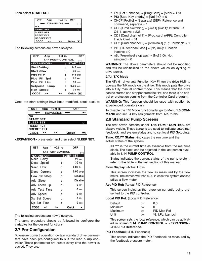
Then select START SET.
The following screens are now displayed.
Once the start settings have been modified, scroll back to
<EXPANSION> press enter and then select SLEEP SET.
The following screens are now displayed.
The same procedure should be followed to configure thevariables for the desired functions.
2.7 Pre-ConfigurationTo ensure correct operation certain standard drive parame-ters have been pre-configured to suit the lead pump con-troller. These parameters are preset every time the power iscycled. They are:
• Fr1 [Ref.1 channel] = [Prog.Card] = (APP) = 170• PSt [Stop Key priority] = [No] (nO) = 0• CHCF [Profile] = [Separate] (SEP): Reference and
command, separate = 1• CCS [Cmd switching] = [C411] (C411): Internal Bit
C411, active = 235• CD1 [Cmd channel 1] = [Prog.card] (APP): Controller
Inside Card = 31• CD2 [Cmd channel 2] = [Terminals] (tEr): Terminals = 1
• PIF [PID feedback ass.] = [No] (nO): Functioninactive = 0
• nSt [Freewheel stop ass.] = [No] (nO): Notassigned = 0
WARNING: The above parameters should not be modifiedand will be reinitialized to the above values on cycling ofdrive power.
2.7.1 T/K Mode
The ATV 61 drive sets Function Key F4 (on the drive HMI) tooperate the T/K mode on the drive. This mode puts the driveinto a fully manual control mode. This means that the drivecan be started and stopped from the HMI and there is no con-trol or protection coming from the Controller Card program.
WARNING: This function should be used with caution byexperienced operators only.
To disable the T/K Mode functionality, go to Menu 1.6 COM-MAND and set F4 key assignment: from T/K to No.
2.8 Standard Pump ScreensThe first seven screens under 1.14 PUMP CONTROL arealways visible. These screens are used to indicate setpoints,feedback, and system status and to set local PID Setpoints.
Time: XX.YY Status: (indicates the run time and theactual status of the system)
XX.YY is the current time as available from the real timeclock. The clock can be adjusted in the last screen avail-able in 1.14 PUMP CONTROL.
Status indicates the current status of the pump system;refer to the table in the last section of this manual.
Flow Display: (Actual Flow)
This screen indicates the flow as measured by the flowmeter. The screen will read 0.00 in case the system doesn’tutilize a flow meter.
Act PID Ref: (Actual PID Reference)
This screen indicates the reference currently being pre-sented to the PID controller.
Local PID Ref: (Local PID Reference)
Default := 0.0 Minimum := 0Maximum := PID Max Ref Unit := %, kPa, bar, psi
This screen sets the local reference, which can be activat-ed in screen 1.14 PUMP CONTROL ~ <EXPANSION>~PID~PID Reference.
PID Feedback: (PID Feedback)
This screen indicates the PID Feedback as measured bythe feedback pressure meter.
11
OFF App +0.0 Hz OFF
NO
SLEEP SET
RESET FLT
NRESET FLT
CODE << Quick
EEXXPPAANNSSIIOONN
>>
START SET
OFF App +0.0 Hz OFF
<EXPANSION> ::: START SET
Start Setting :: 0.5 Bar
:: 30 sec
Pipe Fill P :: 0.4 Bar
:: 25 Hz
:: 10 sec
:: 0.05 u/s
:: 35 Hz
CODE << Quick>>
PPiippee FFiillll LLiimmSSeettppooiinntt RRaammppMMaann SSppeeeedd
Start Delay
PPiippee FFiillll SSppdd
1.14 PUMP CONTROL
NST App +0.0 Hz OFF
NOSTART SETSLEEP SETRESET FLTNRESET FLTCODE << Quick
EEXXPPAANNSSIIOONN
>>
NST App +0.0 Hz OFF
:: SET:: 20 sec
:: 30 Hz
:: 0.00 I/s
:: 0.00 amps
:::::: 0 Hz
:: 0 sec
:: 0 Hz
:: 0 Hz
:: 0 sec
CODE << Quick>>
SSlleeeepp DDeellaayy
AAddvv TTeesstt TTiimmeeAAddvv SSppeeeedd
AAddvv SSlleeeepp
SSlleeeepp SSppeeeeddSSlleeeepp FFllooww
SSllpp BBsstt SSppeeeeddSSllpp BBsstt TTiimmee
Disable
Disable
AAddvv CChheecckk SSpp
SSlleeeepp CCuurrrreennttFFllooww SSww SSlleeeepp
SLEEP1.14 PUMP CONTROL
<EXPANSION>
System Status: (Actual status of the system)
Status indicates the current status of the pump system;refer to the table in the last section of this manual.
Alt Local Ref: (Alternative Local PID Reference)
Default := 0.0Minimum := 0Maximum := PID Max Ref Unit := %, kPa, bar, psi
This screen sets the local reference, which can be acti-vated in screen 1.14 PUMP CONTROL ~ <EXPANSION>~PID~Alt Reference.
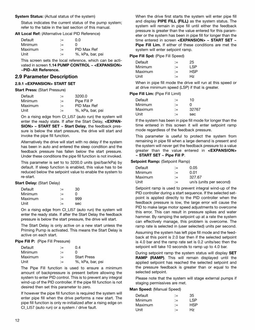
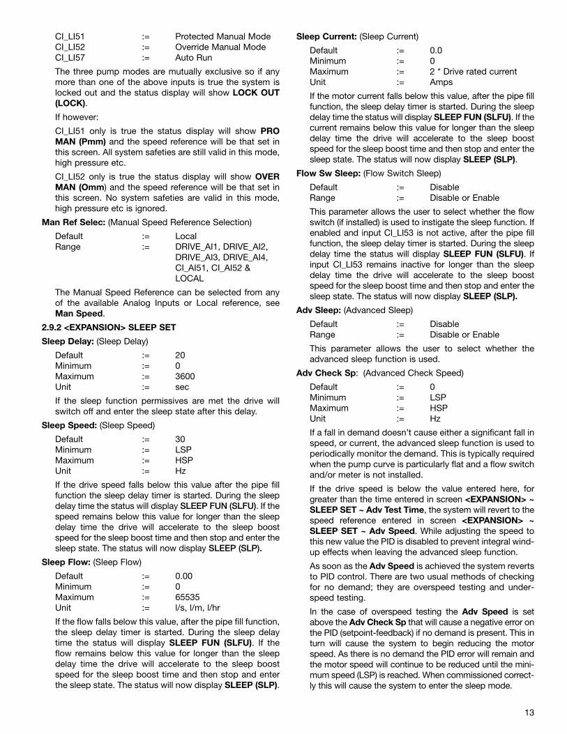
2.9 Parameter Description2.9.1 <EXPANSION> START SET
Start Press: (Start Pressure)
Default := 3200.0Minimum := Pipe Fill PMaximum := PID Max Ref Unit := %, kPa, bar, psi
On a rising edge from CI_LI57 (auto run) the system willenter the ready state. If after the Start Delay, <EXPAN-SION> ~ START SET ~ Start Delay, the feedback pres-sure is below the start pressure, the drive will start andinvoke the pipe fill function.
Alternatively the drive will start with no delay if the systemhas been in auto and entered the sleep condition and thefeedback pressure has fallen below the start pressure.Under these conditions the pipe fill function is not invoked.
This parameter is set to to 3200.0 units (psi/bar/kPa) bydefault. If sleep function is enabled, this value has to bereduced below the setpoint value to enable the system tore-start.
Start Delay: (Start Delay)
Default := 30 Minimum := 0Maximum := 999Unit := sec
On a rising edge from CI_LI57 (auto run) the system willenter the ready state. If after the Start Delay the feedbackpressure is below the start pressure, the drive will start.
The Start Delay is only active on a new start unless thePriming Pump is activated. This means the Start Delay isactive on each start.
Pipe Fill P: (Pipe Fill Pressure)
Default := 0.4 Minimum := 0Maximum := Start PressUnit := %, kPa, bar, psi
The Pipe Fill function is used to ensure a minimumamount of backpressure is present before allowing thesystem to enter PID control. This is to prevent any integralwind-up of the PID controller. If the pipe fill function is notdesired then set this parameter to zero.
If however the pipe fill function is required the system willenter pipe fill when the drive performs a new start. Thepipe fill function is only re-initialized after a rising edge onCI_LI57 (auto run) or a system / drive fault.
When the drive first starts the system will enter pipe filland display PIPE FILL (FILL) as the system status. Thesystem will remain in pipe fill until either the feedbackpressure is greater than the value entered for this param-eter or the system has been in pipe fill for longer than thetime entered in screen <EXPANSION> ~ START SET ~Pipe Fill Lim. If either of these conditions are met thesystem will enter setpoint ramp.
Pipe Fill Spd: (Pipe Fill Speed)
Default := 25 Minimum := LSPMaximum := HSPUnit := Hz
When in pipe fill mode the drive will run at this speed orat drive minimum speed (LSP) if that is greater.
Pipe Fill Lim: (Pipe Fill Limit)
Default := 10Minimum := 0Maximum := 32767Unit := sec
If the system has been in pipe fill mode for longer than thetime entered in this screen it will enter setpoint rampmode regardless of the feedback pressure.
This parameter is useful to protect the system fromremaining in pipe fill when a large demand is present andthe system will never get the feedback pressure to a valuegreater than the value entered in <EXPANSION> ~ START SET ~ Pipe Fill P.
Setpoint Ramp: (Setpoint Ramp)
Default := 0.05 Minimum := 0.01Maximum := 327.67Unit := un/s (units per second)
Setpoint ramp is used to prevent integral wind-up of thePID controller during a start sequence. If the selected set-point is applied directly to the PID controller when thefeedback pressure is low, the large error will cause thePID to make large motor speed adjustments to overcomethis error. This can result in pressure spikes and waterhammer. By ramping the setpoint up at a rate the systemcan effectively manage, this problem is overcome. Theramp rate is selected in (user selected) units per second.
Assuming the system has left pipe fill mode and the feed-back at this point is 2.0 bar then if the selected setpointis 4.0 bar and the ramp rate set is 0.2 units/sec then thesetpoint will take 10 seconds to ramp up to 4.0 bar.
During setpoint ramp the system status will display SETRAMP (RAMP). This will remain displayed until theapplied setpoint has reached the selected setpoint andthe pressure feedback is greater than or equal to theselected setpoint.
Please note that the system will stage external pumps ifstaging permissives are met.
Man Speed: (Manual Speed)
Default := 35 Minimum := LSPMaximum := HSPUnit := Hz
12
CI_LI51 := Protected Manual ModeCI_LI52 := Override Manual ModeCI_LI57 := Auto Run
The three pump modes are mutually exclusive so if anymore than one of the above inputs is true the system islocked out and the status display will show LOCK OUT(LOCK).
If however:
CI_LI51 only is true the status display will show PROMAN (Pmm) and the speed reference will be that set inthis screen. All system safeties are still valid in this mode,high pressure etc.
CI_LI52 only is true the status display will show OVERMAN (Omm) and the speed reference will be that set inthis screen. No system safeties are valid in this mode,high pressure etc is ignored.
Man Ref Selec: (Manual Speed Reference Selection)
Default := LocalRange := DRIVE_AI1, DRIVE_AI2,
DRIVE_AI3, DRIVE_AI4, CI_AI51, CI_AI52 & LOCAL
The Manual Speed Reference can be selected from anyof the available Analog Inputs or Local reference, seeMan Speed.
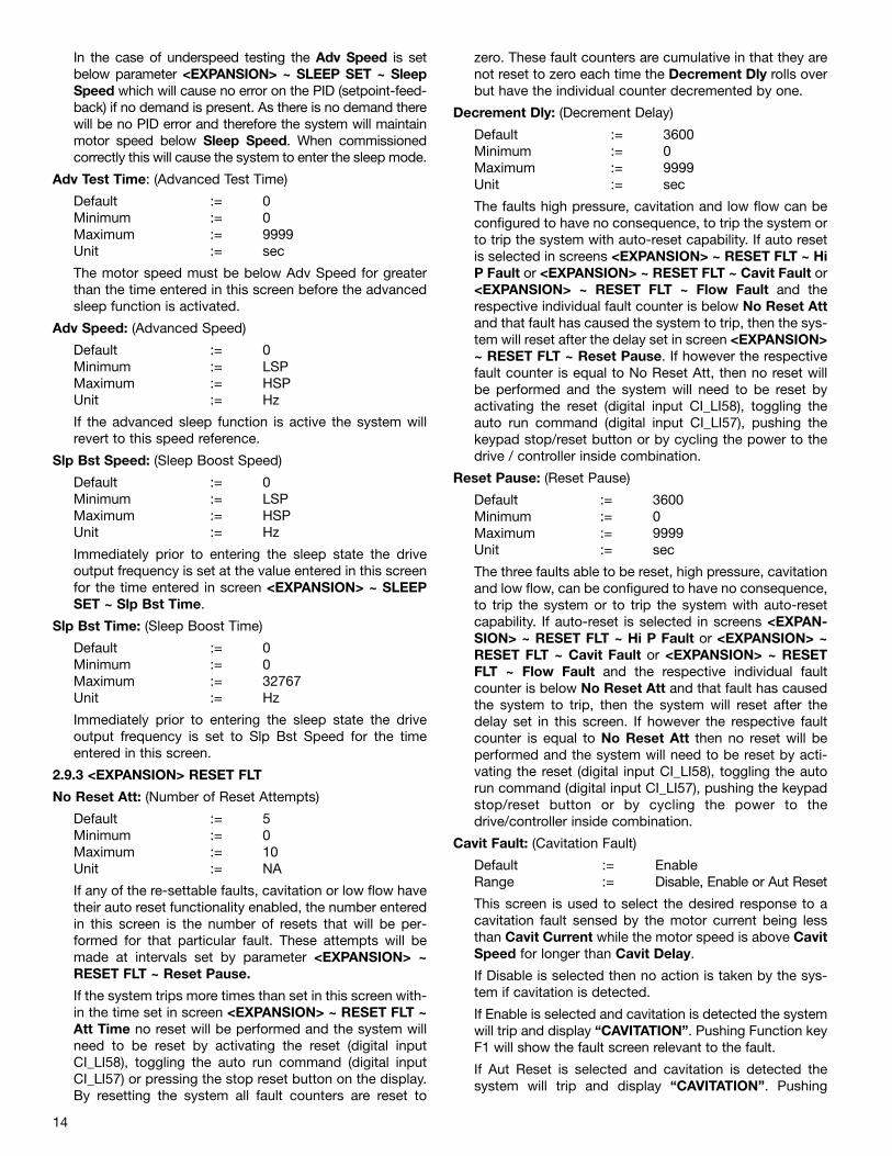
2.9.2 <EXPANSION> SLEEP SET
Sleep Delay: (Sleep Delay)
Default := 20Minimum := 0Maximum := 3600Unit := sec
If the sleep function permissives are met the drive willswitch off and enter the sleep state after this delay.
Sleep Speed: (Sleep Speed)
Default := 30 Minimum := LSPMaximum := HSPUnit := Hz
If the drive speed falls below this value after the pipe fillfunction the sleep delay timer is started. During the sleepdelay time the status will display SLEEP FUN (SLFU). If thespeed remains below this value for longer than the sleepdelay time the drive will accelerate to the sleep boostspeed for the sleep boost time and then stop and enter thesleep state. The status will now display SLEEP (SLP).
Sleep Flow: (Sleep Flow)
Default := 0.00 Minimum := 0Maximum := 65535Unit := l/s, l/m, l/hr
If the flow falls below this value, after the pipe fill function,the sleep delay timer is started. During the sleep delaytime the status will display SLEEP FUN (SLFU). If theflow remains below this value for longer than the sleepdelay time the drive will accelerate to the sleep boostspeed for the sleep boost time and then stop and enterthe sleep state. The status will now display SLEEP (SLP).
Sleep Current: (Sleep Current)
Default := 0.0Minimum := 0Maximum := 2 * Drive rated currentUnit := Amps
If the motor current falls below this value, after the pipe fillfunction, the sleep delay timer is started. During the sleepdelay time the status will display SLEEP FUN (SLFU). If thecurrent remains below this value for longer than the sleepdelay time the drive will accelerate to the sleep boostspeed for the sleep boost time and then stop and enter thesleep state. The status will now display SLEEP (SLP).
Flow Sw Sleep: (Flow Switch Sleep)
Default := Disable Range := Disable or Enable
This parameter allows the user to select whether the flowswitch (if installed) is used to instigate the sleep function. Ifenabled and input CI_LI53 is not active, after the pipe fillfunction, the sleep delay timer is started. During the sleepdelay time the status will display SLEEP FUN (SLFU). Ifinput CI_LI53 remains inactive for longer than the sleepdelay time the drive will accelerate to the sleep boostspeed for the sleep boost time and then stop and enter thesleep state. The status will now display SLEEP (SLP).
Adv Sleep: (Advanced Sleep)
Default := DisableRange := Disable or Enable
This parameter allows the user to select whether theadvanced sleep function is used.
Adv Check Sp: (Advanced Check Speed)
Default := 0 Minimum := LSPMaximum := HSPUnit := Hz
If a fall in demand doesn’t cause either a significant fall inspeed, or current, the advanced sleep function is used toperiodically monitor the demand. This is typically requiredwhen the pump curve is particularly flat and a flow switchand/or meter is not installed.
If the drive speed is below the value entered here, forgreater than the time entered in screen <EXPANSION> ~SLEEP SET ~ Adv Test Time, the system will revert to thespeed reference entered in screen <EXPANSION> ~SLEEP SET ~ Adv Speed. While adjusting the speed tothis new value the PID is disabled to prevent integral wind-up effects when leaving the advanced sleep function.
As soon as the Adv Speed is achieved the system revertsto PID control. There are two usual methods of checkingfor no demand; they are overspeed testing and under-speed testing.
In the case of overspeed testing the Adv Speed is setabove the Adv Check Sp that will cause a negative error onthe PID (setpoint-feedback) if no demand is present. This inturn will cause the system to begin reducing the motorspeed. As there is no demand the PID error will remain andthe motor speed will continue to be reduced until the mini-mum speed (LSP) is reached. When commissioned correct-ly this will cause the system to enter the sleep mode.
13
14
In the case of underspeed testing the Adv Speed is setbelow parameter <EXPANSION> ~ SLEEP SET ~ SleepSpeed which will cause no error on the PID (setpoint-feed-back) if no demand is present. As there is no demand therewill be no PID error and therefore the system will maintainmotor speed below Sleep Speed. When commissionedcorrectly this will cause the system to enter the sleep mode.
Adv Test Time: (Advanced Test Time)
Default := 0 Minimum := 0Maximum := 9999Unit := sec
The motor speed must be below Adv Speed for greaterthan the time entered in this screen before the advancedsleep function is activated.
Adv Speed: (Advanced Speed)
Default := 0 Minimum := LSPMaximum := HSPUnit := Hz
If the advanced sleep function is active the system willrevert to this speed reference.
Slp Bst Speed: (Sleep Boost Speed)
Default := 0 Minimum := LSPMaximum := HSPUnit := Hz
Immediately prior to entering the sleep state the driveoutput frequency is set at the value entered in this screenfor the time entered in screen <EXPANSION> ~ SLEEPSET ~ Slp Bst Time.
Slp Bst Time: (Sleep Boost Time)
Default := 0 Minimum := 0Maximum := 32767Unit := Hz
Immediately prior to entering the sleep state the driveoutput frequency is set to Slp Bst Speed for the timeentered in this screen.
2.9.3 <EXPANSION> RESET FLT
No Reset Att: (Number of Reset Attempts)
Default := 5Minimum := 0Maximum := 10Unit := NA
If any of the re-settable faults, cavitation or low flow havetheir auto reset functionality enabled, the number enteredin this screen is the number of resets that will be per-formed for that particular fault. These attempts will bemade at intervals set by parameter <EXPANSION> ~RESET FLT ~ Reset Pause.
If the system trips more times than set in this screen with-in the time set in screen <EXPANSION> ~ RESET FLT ~Att Time no reset will be performed and the system willneed to be reset by activating the reset (digital inputCI_LI58), toggling the auto run command (digital inputCI_LI57) or pressing the stop reset button on the display.By resetting the system all fault counters are reset to
zero. These fault counters are cumulative in that they arenot reset to zero each time the Decrement Dly rolls overbut have the individual counter decremented by one.
Decrement Dly: (Decrement Delay)
Default := 3600Minimum := 0Maximum := 9999Unit := sec
The faults high pressure, cavitation and low flow can beconfigured to have no consequence, to trip the system orto trip the system with auto-reset capability. If auto resetis selected in screens <EXPANSION> ~ RESET FLT ~ HiP Fault or <EXPANSION> ~ RESET FLT ~ Cavit Fault or<EXPANSION> ~ RESET FLT ~ Flow Fault and therespective individual fault counter is below No Reset Attand that fault has caused the system to trip, then the sys-tem will reset after the delay set in screen <EXPANSION>~ RESET FLT ~ Reset Pause. If however the respectivefault counter is equal to No Reset Att, then no reset willbe performed and the system will need to be reset byactivating the reset (digital input CI_LI58), toggling theauto run command (digital input CI_LI57), pushing thekeypad stop/reset button or by cycling the power to thedrive / controller inside combination.
Reset Pause: (Reset Pause)
Default := 3600Minimum := 0Maximum := 9999Unit := sec
The three faults able to be reset, high pressure, cavitationand low flow, can be configured to have no consequence,to trip the system or to trip the system with auto-resetcapability. If auto-reset is selected in screens <EXPAN-SION> ~ RESET FLT ~ Hi P Fault or <EXPANSION> ~RESET FLT ~ Cavit Fault or <EXPANSION> ~ RESETFLT ~ Flow Fault and the respective individual faultcounter is below No Reset Att and that fault has causedthe system to trip, then the system will reset after thedelay set in this screen. If however the respective faultcounter is equal to No Reset Att then no reset will beperformed and the system will need to be reset by acti-vating the reset (digital input CI_LI58), toggling the autorun command (digital input CI_LI57), pushing the keypadstop/reset button or by cycling the power to thedrive/controller inside combination.
Cavit Fault: (Cavitation Fault)
Default := EnableRange := Disable, Enable or Aut Reset
This screen is used to select the desired response to acavitation fault sensed by the motor current being lessthan Cavit Current while the motor speed is above CavitSpeed for longer than Cavit Delay.
If Disable is selected then no action is taken by the sys-tem if cavitation is detected.
If Enable is selected and cavitation is detected the systemwill trip and display “CAVITATION”. Pushing Function keyF1 will show the fault screen relevant to the fault.
If Aut Reset is selected and cavitation is detected thesystem will trip and display “CAVITATION”. Pushing
15
Function key F1 will show the fault screen relevant to thefault. After the time delay Reset Pause the system willautomatically reset as long as the respective individualfault counter is less than No Reset Att.
Cavit Current: (Cavitation Current)
Default := 0Minimum := 0Maximum := 2 * Drive rated currentUnit := Amps
Cavitation is detected when the motor current is belowthe value entered in this screen while the motor speed isabove Cavit Speed for longer than Cavit Delay.
Cavit Speed: (Cavitation Speed)
Default := 50Minimum := LSPMaximum := HSPUnit := Hz
Cavitation is detected when the motor speed is above thevalue entered in this screen while the motor current isbelow Cavit Current for longer than Cavit Delay.
Cavit Delay: (Cavitation Delay)
Default := 10Minimum := 0Maximum := 999Unit := sec
Cavitation is detected when the motor speed is aboveCavit Speed while the motor current is below CavitCurrent for longer than the value entered in this screen.
Flow Fault: (Flow Fault)
Default := EnableRange := Disable, Enable or Aut Reset
This screen is used to select the desired response to aflow fault.
There are two ways the system detects a flow fault, eitherby sensing digital input CI_LI53 is inactive or by the flowfeedback being below Lo Flow Level. The user selectswhich sensing mechanism to use in screen <EXPAN-SION> ~ RESET FLT ~ Lo Flow Sel.
Regardless of the sensing mechanism selected, low flowprotection can be disabled during pipe fill.
This is done in screen <EXPANSION> ~ RESET FLT ~ FillFlow Pro assuming Fill Flow Pro was set to No (no pro-tection during pipe fill) and Flow Rate or Either wasselected in screen <EXPANSION> ~ RESET FLT ~ LoFlow Sel.
On completion of the Pipe Fill function and the low flowprotection start delay, Lo Flo Delay, a low flow faultoccurs if the flow feedback is below Lo Flow Level forlonger than Lo Flo Filter and the motor speed is aboveLo Flo Speed.
Alternatively, assuming Fill Flow Pro was set to No (no pro-tection during pipe fill) and Flow Sw or Either was selectedin screen <EXPANSION> ~ RESET FLT ~ Lo Flow Sel, oncompletion of the Pipe Fill function and the low flow protec-tion start delay, Lo Flo Delay, a low flow fault occurs if dig-ital input CI_LI53 is inactive for longer than Lo Flo Filter andthe motor speed is above Lo Flo Speed.
If Disable is selected in this screen then no action is takenby the system if low flow is detected.
Alternatively if Enable is selected and a flow fault is gen-erated due to flow feedback the system will trip and dis-play “FLOW RATE”. If a flow fault is generated due todigital input CI_LI53 being inactive the system will tripand display “NO FLOW”. Pushing Function key F1 willshow the fault screen relevant to the fault.
Alternatively if Aut Reset is selected and a flow fault isgenerated due to flow feedback the system will trip anddisplay “FLOW RATE”. If a flow fault is generated due todigital input CI_LI53 being inactive the system will tripand display “NO FLOW”. Pushing Function key F1 willshow the fault screen relevant to the fault. After the timedelay Reset Pause the system will automatically reset aslong as the respective individual fault counter is less thanNo Reset Att.
Lo Flow Sel: (Low Flow Selection)
Default := Flow SwRange := Flow Rate, Flow Sw or Either
This screen selects whether the flow feedback, the flowswitch or both are used to trip the system under low flowconditions.
Lo Flo Level: (Low Flow Level)
Default := 0Minimum := 0Maximum := 327.67Unit := l/s, l/m, l/hr
If Flow Rate or Rate or Sw is selected in screen Lo FlowSel then the flow rate must be below this level for a flowrate generated fault to occur.
Lo Flo Speed: (Low Flow Speed)
Default := 25Minimum := LSPMaximum := HSPUnit := Hz
The motor speed must be above the value entered in thisscreen for a flow fault to be generated.
Lo Flo Delay: (Low Flow Delay)
Default := 30Minimum := 0Maximum := 999Unit := sec
If low flow protection during Pipe Fill is enabled in screenFill Flow Pro then as soon as the drive starts the LowFlow Delay is started. A flow fault can only occur after thisdelay has timed out.
Alternatively, if low flow protection during Pipe Fill is dis-abled in screen Fill Flow Pro then as soon as the Pipe Fillhas finished the Low Flow Delay is started. A flow faultcan only occur after this delay has timed out.
Lo Flo Filter: (Low Flow Filter)
Default := 2Minimum := 0Maximum := 999Unit := sec
After Lo Flo Delay the flow rate or flow switch permis-
sives must be met for greater than this time before thesystem will trip. This value is a de-bounce time to preventnuisance faults.
Fill Flow Pro: (Fill Flow Protection)
Default := NO Range := NO or YES
If this function is enabled (YES selected) the low flow pro-tection is active during pipe fill. If disabled (NO selected) thelow flow protection is only active after pipe fill has finished.
2.9.4 <EXPANSION> NRESET FLT
Cycle Time: (Cycle Time)
Default := 60Minimum := 0Maximum := 3600Unit := sec
If the drive transitions from the NST state to the Run state(drive starts), the cycle counter is incremented by one. Ifthe Cycle Counter is greater than <EXPANSION> ~ NRE-SET FLT ~ Cycle Count the system will trip and require areset via activation of CI_LI58, toggling the auto com-mand (CI_LI57) or pushing the drive stop / reset button.
The cycle count is reset to zero each time the period setin this screen elapses.
Cycle Count: (Cycle count)
Default := 3Minimum := 0Maximum := 99Unit := Na
If the drive transitions from the NST state to the Run state(drive starts), the cycle counter is incremented by one. Ifthe Cycle Counter is greater than <EXPANSION> ~ NRE-SET FLT ~ Cycle Count the system will trip and require areset via activation of CI_LI58, toggling the auto com-mand (CI_LI57) or pushing the drive stop / reset button.
Min Press Flt: (Minimum Pressure Fault)
Default := Enable Range := Disable or Enable
If the drive is running and the system is not in OverrideManual mode and the feedback pressure is less than<EXPANSION> ~ NRESET FLT ~ Min Press Lev forlonger than <EXPANSION> ~ NRESET FLT ~ Min PressDly, the system will trip and display MIN PRESS.
Min Press Lev: (Minimum Pressure Level)
Default := 0.0Minimum := 0.0Maximum := 3276.7Unit := %, kPa, bar, psi
If the drive is running and the system is not in OverrideManual mode and the feedback pressure is less than<EXPANSION> ~ NRESET FLT ~ Min Press Lev forlonger than <EXPANSION> ~ NRESET FLT ~ Min PressDly, the system will trip and display MIN PRESS.
Min Press Dly: (Minimum Pressure Delay)
Default := 10Minimum := 0Maximum := 3600Unit := sec
If the drive is running and the system is not in OverrideManual mode and the feedback pressure is less than<EXPANSION> ~ NRESET FLT ~ Min Press Lev forlonger than <EXPANSION> ~ NRESET FLT ~ Min PressDly, the system will trip and display MIN PRESS.
Low Lev: (Low Level)
Default := EnableRange := Disable or Enable
If the drive is running and the system is not in OverrideManual mode and digital input CI_LI60 is inactive forlonger than <EXPANSION> ~ NRESET FLT ~ Low LevDly and this screen is set to Enable, the system will tripand display LOW LEVEL.
If CI_LI60 is inactive and a start command is given thedrive will remain off with the system status displayingLOW LEVEL (LLEV) periodically.
Low Lev Dly: (Low Level Delay)
Default := 2Minimum := 0Maximum := 3600Unit := sec
If the drive is running and the system is not in OverrideManual mode and digital input CI_LI60 is inactive forlonger than the time entered in this screen and Low Levis set to Enable, the system will trip and display LOWLEVEL.
Hi Temp: (High Temperature)
Default := EnableRange := Disable or Enable
If the drive is running and the system is not in OverrideManual mode and digital input DRIVE_LI4 is inactive forone second and this screen is set to Enable, the systemwill trip and display HIGH TEMP.
If DRIVE_LI4 is inactive and a start command is given, thedrive will remain off with the system status displayingHIGH TEMP (HI T) periodically.
2.9.5 <EXPANSION> SENSORS
Outlet TX Max: (Outlet Transducer Maximum)
Default := 10.0 Minimum := 0.1Maximum := 3276.7
This screen is used to inform the system of the range ofthe transducer being used to measure outlet / dischargepressure. It is always assumed that the minimum is zero(i.e., a 0-10bar transducer would be selected rather thana 2-10 bar device). If the transducer used is 4-20mA and0-10.0 bar then 10.0 should be entered in this screen, andbar should be selected as pressure unit.
Please note that if one of the Controller Inside analoginputs is used for outlet / discharge pressure, it must becorrectly configured in screens <EXPANSION> ~ CON-FIG ~ CI_AI51 Type or <EXPANSION> ~ CONFIG ~CI_AI52 Type respectively.
If one of the drive analog inputs is used it must be con-figured to suit the device being used under 1.5INPUTS/OUTPUTS CFG.
16
Inlet TX Max: (Inlet Transducer Maximum)
Default := 10.0 Minimum := 0.1Maximum := 3276.7
This screen is used to inform the system of the range ofthe transducer being used to measure inlet / suctionpressure. It is always assumed that the minimum is zero(i,e., a 0-10bar transducer would be selected rather thana 2-10 bar device). If the transducer used is 4-20mA and0-10.0 bar then 10.0 should be entered in this screen andbar should be selected as pressure unit.
Please note that if one of the Controller Inside analoginputs is used for inlet / suction pressure, it must be cor-rectly configured in screens <EXPANSION> ~ CONFIG ~CI_AI51 Type or <EXPANSION> ~ CONFIG ~ CI_AI52Type respectively.
If one of the drive analog inputs is used it must be con-figured to suit the device being used under 1.5INPUTS/OUTPUTS CFG.
Press Units: (Pressure Units)
Default := barRange := %, kPa, bar, psi, l/s,
l/m or l/h
This screen sets the unit displayed for all otherscreens that display or allow modification of a pres-sure value. The unit selected is for display purposesonly and in no way affects any numerical values.
When changing the unit for display, the other screens in thissub-group <EXPANSION> ~SENSORS ~ are not updateduntil another sub-group is selected and this one re-entered.
Flow Source: (Flow Source)
Default := NONERange := NONE, CI_LI59,
DRIVE_AI1, DRIVE_AI2,DRIVE_AI3, DRIVE_AI4,CI_AI51, CI_AI52
This screen configures what type of transducer is used tomeasure flow. If a pulse flow meter is used, CI_LI59 mustbe selected. If an analog meter is used, one of the listedanalog sources should be selected. If no flow transduceris used, NONE should be selected.
Please note the following:
If one of the Controller Inside analog inputs is used, itmust be correctly configured in screens <EXPANSION>~ CONFIG ~ CI_AI51 Type or <EXPANSION> ~ CONFIG~ CI_AI52 Type respectively.
If any of the analog sources are selected, the adjustablerange is dependent on the flow unit that is selected inscreen <EXPANSION> ~ SENSORS ~ Flow Units.
If litres / s is selected there will be two decimal places,
If Litres / m is selected there will be one decimal place,
If Litres / h is selected there will be no decimal places inthe following screens:
Flow Display
<EXPANSION> ~ SLEEP SET ~ Sleep Flow<EXPANSION> ~ RESET FLT ~ Lo Flow Level<EXPANSION> ~ SENSORS ~ Flow AIN Tx
<EXPANSION> ~ FLOW LMT ~ Flow Limit<EXPANSION> ~ FLOW LMT ~ Flo Lmt Reset<EXPANSION> ~ FLOW COMP ~ Known Flow<EXPANSION> ~ FLOW COMP ~ Known Flow
This equates to a maximum measured flow rate of 655.35litres per second, 6553.5 litres per minute or 65535 litresper hour when an analog flow meter source is used.
If CI_LI59 is selected the amount of decimal places forthe above listed screens is based on the following:
If <EXPANSION> ~ SENSORS ~ Volume divided by<EXPANSION> ~ SENSORS ~ Pulses/volume is lessthan 0.1, then two decimal places are used.
If <EXPANSION> ~ SENSORS ~ Volume divided by<EXPANSION> ~ SENSORS ~ Pulses/volume is lessthan or equal to 1, one decimal place is used.Otherwise no decimal places are used.
Therefore a pulse flow transducer with 20 pulses per litrewill cause two decimal places, a pulse flow transducerwith 5 pulses per litre will cause one decimal place and apulse flow transducer with 1 pulse per 10 litres will causeno decimal places.
The maximum frequency possible if CI_LI59 is used aspulse flow input is 5kHz.
Flow AIN Tx: (Flow Transducer Analog Input Maximum)
Default := 0.00Minimum := 0.00Maximum := 65535
This screen is used to inform the system of the range ofthe transducer being used to measure flow if an analogtransducer is used. This screen is redundant if CI_LI59 orNONE was selected in screen <EXPANSION> ~SEN-SORS~ Flow Source.
It is always assumed that the minimum is zero (i.e., a 0-10bar transducer would be selected rather than a 2-10 bardevice). If the transducer used is 0-20mA and 0-10000litres/s, then 10000 should be entered in this screen andlitres/s should be selected as flow unit.
Please note that if one of the Controller Inside analoginputs is used for inlet / suction pressure, then it must becorrectly configured in screens <EXPANSION> ~ CON-FIG ~ CI_AI51 Type or <EXPANSION> ~ CONFIG ~CI_AI52 Type respectively.
If one of the drive analog inputs is used, it must be con-figured to suit the device being used under 1.5INPUTS/OUTPUTS CFG.
Pulses/volume: (Pulses per volume)
Default := 1.00Minimum := 0.1Maximum := 655.35Unit := pu/v
If a pulse flow transducer is used, this screen sets theamount of pulses expected per volume set in screen<EXPANSION> ~ SENSORS ~ Volume.
See also <EXPANSION> ~ SENSORS ~ Flow Source fora description of scaling effects.
17
Volume: (Volume)
Default := 1Minimum := 1Maximum := 65535Unit := pu/v
If a pulse flow transducer is used, this screen sets the vol-ume expected per pulse set in screen <EXPANSION> ~SENSORS ~ Pulses/volume.
See also <EXPANSION> ~ SENSORS ~ Flow Source fora description of scaling effects.
Flow Units: (Flow Units)
Default := l/sRange := %, kPa, bar, psi, l/s,
l/m or l/h
This screen sets the unit displayed for all other screensthat display or allow modification of a flow rate.
See also <EXPANSION> ~ SENSORS ~ Flow Source fora description of scaling effects.
Flow Filter: (Flow Filter)
Default := 0Minimum := 0Maximum := 65535Unit := sec
If a pulse flow transducer is used, this screen sets the fil-ter time base. If the signal is of a reasonably high frequen-cy, some instability may be present. This filter is used todampen the rate of change of the derived flow rate.
WARNING: If the value entered is too high, long delaysmay be present between a change of flow and anydesired evasive action taking place.
CAN Flow dp: (CAN Flow Decimal Places)
Default := 0Minimum := 0Maximum := 2Unit := d.p
This screen is used to scale the input flow from the CANnetwork. O to 2 decimal places can be selected. Thisscreen is only used if CAN is selected as the flow source.
2.9.6 <EXPANSION> FLOW LMT
Activate Lim: (Activate Limit)
Default := Disable Range := Disable or Enable
This parameter enables or disables the flow limit functionof the pump controller.
If flow limiting is enabled and the measured flow increasesto a level greater than <EXPANSION> ~ FLOW LIMIT ~Flow Limit, the controller immediately ceases PID controland begins to decelerate the motor at the flow limit rate setin screen <EXPANSION> ~ FLOW LIMIT ~ Flow LmtRamp. The motor will continue to decelerate until suchtime as the measured flow is below Flow Limit. At this timethe current motor speed is maintained. The system willremain in flow limit until such time as the measured flow isless than <EXPANSION> ~ FLOW LIMIT ~ Flow LmtReset when the system again reverts to PID control.
Flow Limit: (Flow Limit)
Default := 0.0 Minimum := Flo Lmt ResetMaximum := 32767Unit := %, kPa, bar, psi, l/s, l/m
or l/h
If the flow limit function is enabled, flow limiting action isinitiated when the measured flow increases to a levelgreater than that entered in this screen.
Flo Lmt Reset: (Flow Limit Reset)
Default := 0.0 Minimum := 0.0Maximum := Flow LimitUnit := %, kPa, bar, psi, l/s, l/m
or l/h
If the flow limit function is enabled, flow limiting action isterminated when the measured flow decreases to a levelless than that entered in this screen.
Flow Lmt Ramp: (Flow Limit Ramp)
Default := 10.0 Minimum := 0.0Maximum := 999.9Unit := sec
If the flow limit function is enabled, this is the rate atwhich the motor will be decelerated when the measuredflow is above Flow Lmt.
2.9.7 <EXPANSION> PID
PID Reference: (PID Reference)
Default := Local Range := DRIVE_AI1, DRIVE_AI2,
DRIVE_AI3, DRIVE_AI4,CI_AI51, CI_AI52 or LOCAL
This parameter is used to select the reference for thepump controller PID.
Please note that if one of the Controller Inside analog inputsis used for PID Reference, it must be correctly configured inscreens <EXPANSION> ~ CONFIG ~ CI_AI51 Type or<EXPANSION> ~ CONFIG ~ CI_AI52 Type respectively.
If one of the drive analog inputs is used, it must be con-figured to suit the device being used under 1.5INPUTS/OUTPUTS CFG.
PID Max Ref: (PID Maximum Reference)
Default := 3200.0Minimum := 0.0Maximum := 3276.7Unit := %, kPa, bar, psi
This parameter sets the maximum setpoint that can everbe applied to the pump controller PID. This can be usedto prevent inadvertent operator error during adjustmentof the PID setpoint.
PID Feedback: (PID Feedback)
Default := DRIVE_AI2 Range := DRIVE_AI1, DRIVE_AI2,
DRIVE_AI3, DRIVE_AI4,CI_AI51, CI_AI52 or CAN
18
This parameter is used to select the Feedback for thepump controller PID.
Please note that if one of the Controller Inside analog inputsis used for PID Feedback, it must be correctly configured inscreens <EXPANSION> ~ CONFIG ~ CI_AI51 Type or<EXPANSION> ~ CONFIG ~ CI_AI52 Type respectively.
If flow is to be used as the PID feedback, please ensure thatthe flow transducer details have been entered correctly inthe <EXPANSION> ~ SENSORS screens prior to operation.
If one of the drive analog inputs is used it must be con-figured to suit the device being used under 1.5INPUTS/OUTPUTS CFG.
PID Gain: (PID Gain)
Default := +1.40Minimum := -100.00Maximum := +100.00Unit := x
This parameter sets proportional gain of the custom PIDcontroller.
PID Integral: (PID Integral)
Default := 2.00Minimum := 0.00Maximum := 100.00Unit := sec
This parameter sets integral gain of the custom PID con-troller.
PID Deriv: (PID Derivative)
Default := 0.00Minimum := 0.00Maximum := 100.00Unit := sec
This parameter sets derivative gain of the custom PIDcontroller and is not typically altered.
PID Accel: (PID Acceleration)
Default := 5.0Minimum := 0.0Maximum := 999.9Unit := sec
This parameter sets the minimum time required for the PIDcontroller to accelerate the motor from zero speed tomotor rated frequency (FrS) when in PID control. This rateis used whenever the actual motor speed (rFr) is above themotor low speed (LSP) and PID control is active (i.e., notflow limiting and no fault conditions and not stopping).
PID Decel: (PID Deceleration)
Default := 5.0Minimum := 0.0Maximum := 999.9Unit := sec
This parameter sets the minimum time required for thePID controller to decelerate the motor from motor ratedfrequency (FrS) to zero speed when in PID control. Thisrate is used whenever the actual motor speed (rFr) isabove the motor low speed (LSP) and PID control isactive (i.e., not flow limiting and no fault conditions andnot stopping).
Strt Acc Rate: (Starting Acceleration Rate)
Default := 3.0Minimum := 0.0Maximum := 999.9Unit := sec
This parameter sets the time required for the system toaccelerate the motor from zero speed to motor rated fre-quency (FrS). This rate is used whenever the actual motorspeed (rFr) is below the motor low speed (LSP) settingand no fault conditions are present.
Stp Dec Rate: (Stopping Deceleration Rate)
Default := 3.0Minimum := 0.0Maximum := 999.9Unit := sec
This parameter sets the time required for the system todecelerate from motor rated frequency (FrS) to zero speed.This rate is used whenever a stop command is present.
Alt Reference: (Alternative Reference)
Default := Local Range := DRIVE_AI1, DRIVE_AI2,
DRIVE_AI3, DRIVE_AI4,CI_AI51, CI_AI52 or LOCAL
This parameter is used to select the alternative referencefor the pump controller PID. This reference becomesactive when drive digital input two (DRIVE_LI2) is active.
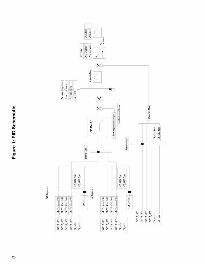
See Figure 1.
2.9.8 <EXPANSION> STAGE
The Multi VSD can be used to stage up to 3 additionalpumps. This means the additional pumps must be connect-ed to the host drive controller card via CANopen.
Number of EXT: (Number of External Pumps)
Default := 0 Minimum := 0Maximum := 3
This parameter sets the number of auxiliary pumps thatare installed.
Note: The number of drives as configured in this param-eter is not related to the number of drives as set up in the<AUTO-COMM> expansion menu.
Duty Sharing: (Duty Sharing)
Default := Enable Range := ON or OFF
If duty sharing is enabled and an auxiliary pump isrequired, the pump with the least amount of run hours willalways be started first. If an auxiliary pump is required tobe destaged, the pump with the most run hours willalways be stopped first. If duty sharing is disabled, thepumps will be started and stopped numerically (i.e., 1 onthen 2 on then 3 on 3 off then 2 off then 1 off).
Parameter set <EXPANSION> ~ SAVED TIM ~ shows thesaved run time hours for all pumps.
Stage Mode: (Stage Mode)
Default := Sp+Pr+Dly Range := Sp+Pr+Dly, Sp+Pr, Sp+Dly,
Sp Only, Pr+Dly, Pr Only
19
20
PID
OU
TPU
T
DRI
VE_A
I1
DRI
VE_A
I2
DRI
VE_A
I3
DRI
VE_A
I4
CI_A
I51
CI_A
I52
LOCA
L
PID
Max
Ref
DRI
VE
SCA
LIN
G
CI_A
I51
Type
CI_A
I52
Type
DRI
VE
SCA
LIN
G
DRI
VE
SCA
LIN
G
DRI
VE
SCA
LIN
GPID
Ref
eren
ce
DRI
VE_A
I1
DRI
VE_A
I2
DRI
VE_A
I3
DRI
VE_A
I4
CI_A
I51
CI_A
I52
Out
let T
x M
ax
CI_A
I51
Type
CI_A
I52
Type
PID
Fee
dbac
k
Driv
e O
ff
+
Flow
Com
pens
atio
n O
utpu
t
-
Inle
t Pro
tect
ion
Out
put
Setp
oint
Ram
p
PID
Gai
n
PID
Inte
gral
PID
Der
ivat
ive
PID
Dec
el
PID
Acc
el
Pipe
Fill
Act
ive
Flow
Lim
it A
ctiv
e
Adv
ance
Sle
ep A
ctiv
e
DRI
VE_A
I1
DRI
VE_A
I2
DRI
VE_A
I3
DRI
VE_A
I4
CI_A
I51
CI_A
I52
ALT
LOCA
L
DRI
VE
SCA
LIN
G
CI_A
I51
Type
CI_A
I52
Type
DRI
VE
SCA
LIN
G
DRI
VE
SCA
LIN
G
DRI
VE
SCA
LIN
GAlt R
efer
ence
DRI
VE_L
I2
+-
Fig
ure
1: P
ID S
chem
atic
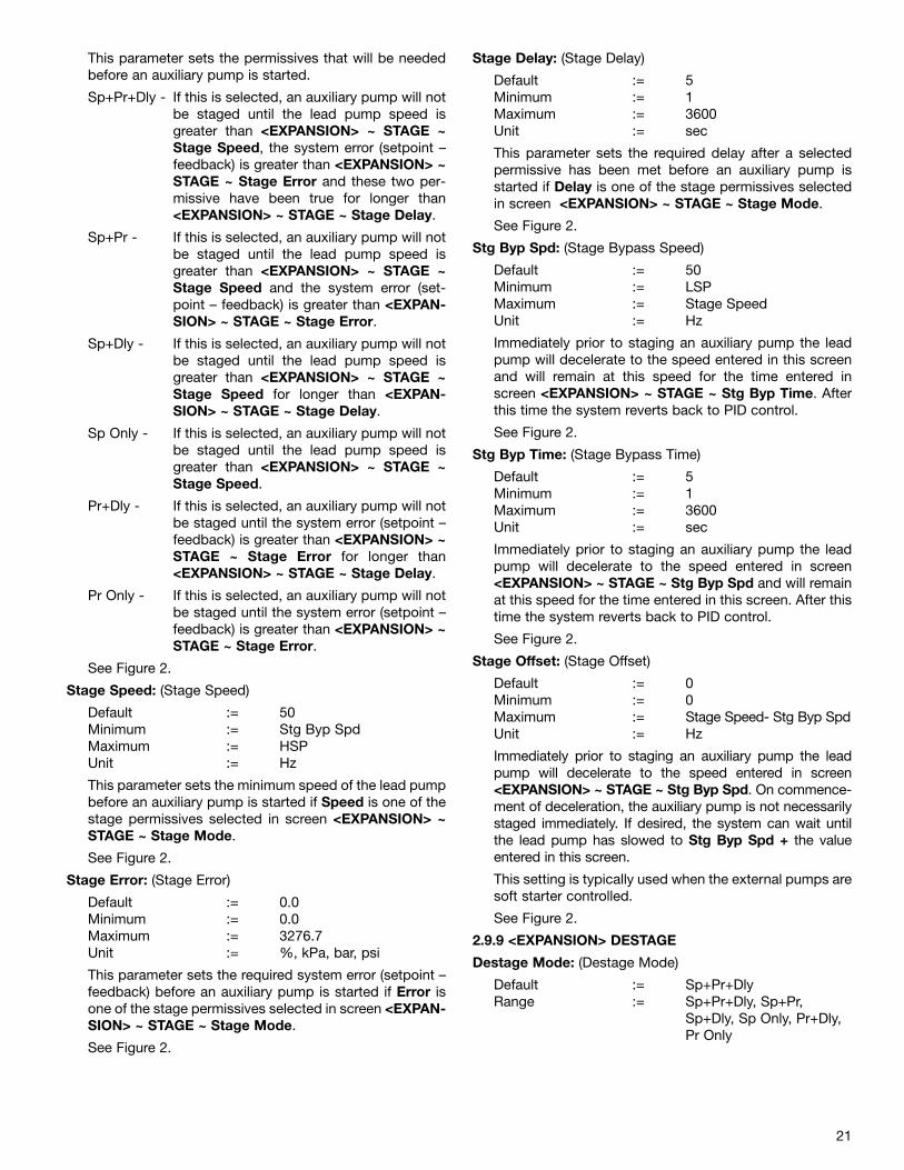
21
This parameter sets the permissives that will be neededbefore an auxiliary pump is started.
Sp+Pr+Dly - If this is selected, an auxiliary pump will notbe staged until the lead pump speed isgreater than <EXPANSION> ~ STAGE ~Stage Speed, the system error (setpoint –feedback) is greater than <EXPANSION> ~STAGE ~ Stage Error and these two per-missive have been true for longer than<EXPANSION> ~ STAGE ~ Stage Delay.
Sp+Pr - If this is selected, an auxiliary pump will notbe staged until the lead pump speed isgreater than <EXPANSION> ~ STAGE ~Stage Speed and the system error (set-point – feedback) is greater than <EXPAN-SION> ~ STAGE ~ Stage Error.
Sp+Dly - If this is selected, an auxiliary pump will notbe staged until the lead pump speed isgreater than <EXPANSION> ~ STAGE ~Stage Speed for longer than <EXPAN-SION> ~ STAGE ~ Stage Delay.
Sp Only - If this is selected, an auxiliary pump will notbe staged until the lead pump speed isgreater than <EXPANSION> ~ STAGE ~Stage Speed.
Pr+Dly - If this is selected, an auxiliary pump will notbe staged until the system error (setpoint –feedback) is greater than <EXPANSION> ~STAGE ~ Stage Error for longer than<EXPANSION> ~ STAGE ~ Stage Delay.
Pr Only - If this is selected, an auxiliary pump will notbe staged until the system error (setpoint –feedback) is greater than <EXPANSION> ~STAGE ~ Stage Error.
See Figure 2.
Stage Speed: (Stage Speed)
Default := 50 Minimum := Stg Byp SpdMaximum := HSPUnit := Hz
This parameter sets the minimum speed of the lead pumpbefore an auxiliary pump is started if Speed is one of thestage permissives selected in screen <EXPANSION> ~STAGE ~ Stage Mode.
See Figure 2.
Stage Error: (Stage Error)
Default := 0.0Minimum := 0.0Maximum := 3276.7Unit := %, kPa, bar, psi
This parameter sets the required system error (setpoint –feedback) before an auxiliary pump is started if Error isone of the stage permissives selected in screen <EXPAN-SION> ~ STAGE ~ Stage Mode.
See Figure 2.
Stage Delay: (Stage Delay)
Default := 5Minimum := 1Maximum := 3600Unit := sec
This parameter sets the required delay after a selectedpermissive has been met before an auxiliary pump isstarted if Delay is one of the stage permissives selectedin screen <EXPANSION> ~ STAGE ~ Stage Mode.
See Figure 2.
Stg Byp Spd: (Stage Bypass Speed)
Default := 50Minimum := LSPMaximum := Stage SpeedUnit := Hz
Immediately prior to staging an auxiliary pump the leadpump will decelerate to the speed entered in this screenand will remain at this speed for the time entered inscreen <EXPANSION> ~ STAGE ~ Stg Byp Time. Afterthis time the system reverts back to PID control.
See Figure 2.
Stg Byp Time: (Stage Bypass Time)
Default := 5Minimum := 1Maximum := 3600Unit := sec
Immediately prior to staging an auxiliary pump the leadpump will decelerate to the speed entered in screen<EXPANSION> ~ STAGE ~ Stg Byp Spd and will remainat this speed for the time entered in this screen. After thistime the system reverts back to PID control.
See Figure 2.
Stage Offset: (Stage Offset)
Default := 0Minimum := 0Maximum := Stage Speed- Stg Byp SpdUnit := Hz
Immediately prior to staging an auxiliary pump the leadpump will decelerate to the speed entered in screen<EXPANSION> ~ STAGE ~ Stg Byp Spd. On commence-ment of deceleration, the auxiliary pump is not necessarilystaged immediately. If desired, the system can wait untilthe lead pump has slowed to Stg Byp Spd + the valueentered in this screen.
This setting is typically used when the external pumps aresoft starter controlled.
See Figure 2.
2.9.9 <EXPANSION> DESTAGE
Destage Mode: (Destage Mode)
Default := Sp+Pr+Dly Range := Sp+Pr+Dly, Sp+Pr,
Sp+Dly, Sp Only, Pr+Dly, Pr Only
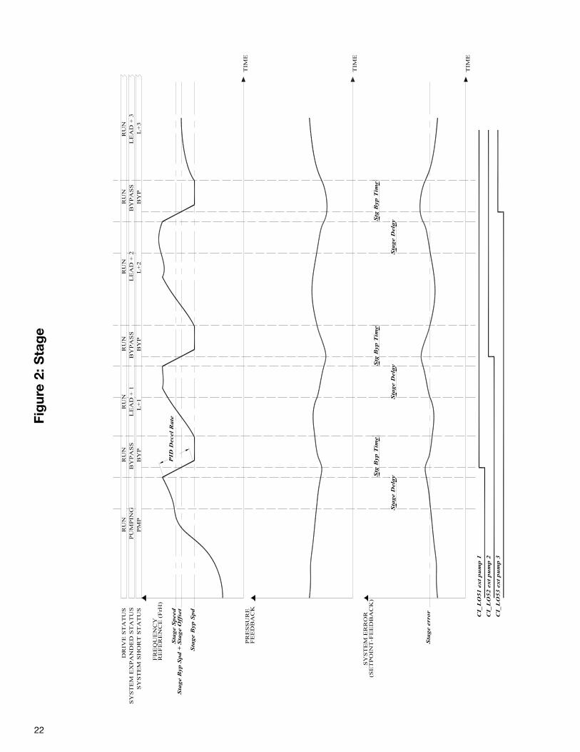
22
Sta
ge B
yp S
pd
DR
IVE
ST
AT
US
TIM
E
SY
ST
EM
EX
PA
ND
ED
ST
AT
US
SY
ST
EM
SH
OR
T S
TA
TU
SP
UM
PIN
GP
MP
RU
N
Sta
ge S
peed
CI_
LO
51 e
xt
pu
mp 1
FR
EQ
UE
NC
YR
EF
ER
EN
CE
(F
rH)
TIM
E
eta
R le
ce
D DI
P
CI_
LO
52 e
xt
pu
mp 2
CI_
LO
53 e
xt
pu
mp 3
Sta
ge B
yp S
pd +
Sta
ge O
ffse
t
PR
ES
SU
RE
FE
ED
BA
CK
TIM
E
Sta
ge e
rror
SY
ST
EM
ER
RO
R
Sta
ge D
ela
yS
tage D
ela
yS
tage D
ela
y
Stg
Byp T
ime
Stg
Byp T
ime
Stg
Byp T
ime
BY
PA
SS
BY
P
RU
NL
EA
D +
1L
+1
RU
NB
YP
AS
SB
YP
RU
NL
EA
D +
2L
+2
RU
NB
YP
AS
SB
YP
RU
NL
EA
D +
3L
+3
RU
N
(SE
TP
OIN
T-F
EE
DB
AC
K)
Fig
ure
2: S
tag
e
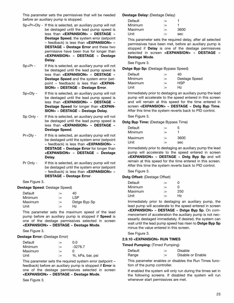
23
This parameter sets the permissives that will be neededbefore an auxiliary pump is stopped.
Sp+Pr+Dly - If this is selected, an auxiliary pump will notbe destaged until the lead pump speed isless than <EXPANSION> ~ DESTAGE ~Destage Speed, the system error (setpoint– feedback) is less than <EXPANSION> ~DESTAGE ~ Destage Error and these twopermissive have been true for longer than<EXPANSION> ~ DESTAGE ~ DestageDelay.
Sp+Pr - If this is selected, an auxiliary pump will notbe destaged until the lead pump speed isless than <EXPANSION> ~ DESTAGE ~Destage Speed and the system error (set-point – feedback) is less than <EXPAN-SION> ~ DESTAGE ~ Destage Error.
Sp+Dly - If this is selected, an auxiliary pump will notbe destaged until the lead pump speed isless than <EXPANSION> ~ DESTAGE ~Destage Speed for longer than <EXPAN-SION> ~ DESTAGE ~ Destage Delay.
Sp Only - If this is selected, an auxiliary pump will notbe destaged until the lead pump speed isless than <EXPANSION> ~ DESTAGE ~Destage Speed.
Pr+Dly - If this is selected, an auxiliary pump will notbe destaged until the system error (setpoint– feedback) is less than <EXPANSION> ~DESTAGE ~ Destage Error for longer than<EXPANSION> ~ DESTAGE ~ DestageDelay.
Pr Only - If this is selected, an auxiliary pump will notbe destaged until the system error (setpoint– feedback) is less than <EXPANSION> ~DESTAGE ~ Destage Error.
See Figure 3.
Destage Speed: Destage Speed)
Default := 40 Minimum := LSPMaximum := Dstge Byp SpUnit := Hz
This parameter sets the maximum speed of the leadpump before an auxiliary pump is stopped if Speed isone of the destage permissives selected in screen<EXPANSION> ~ DESTAGE ~ Destage Mode.
See Figure 3.
Destage Error: (Destage Error)
Default := 0.0Minimum := -3276.7Maximum := 0Unit := %, kPa, bar, psi
This parameter sets the required system error (setpoint –feedback) before an auxiliary pump is stopped if Error isone of the destage permissives selected in screen<EXPANSION> ~ DESTAGE ~ Destage Mode.
See Figure 3.
Destage Delay: (Destage Delay)
Default := 1Minimum := 1Maximum := 3600Unit := sec
This parameter sets the required delay, after all selectedpermissives have been met, before an auxiliary pump isstopped if Delay is one of the destage permissivesselected in screen <EXPANSION> ~ DESTAGE ~Destage Mode.
See Figure 3.
Dstge Byp Sp: (Destage Bypass Speed)
Default := 40Minimum := Destage SpeedMaximum := HSPUnit := Hz
Immediately prior to destaging an auxiliary pump the leadpump will accelerate to the speed entered in this screenand will remain at this speed for the time entered inscreen <EXPANSION> ~ DESTAGE ~ Dstg Byp Time.After this time the system reverts back to PID control.
See Figure 3.
Dstg Byp Time: (Destage Bypass Time)
Default := 5Minimum := 1
Maximum := 3600Unit := sec
Immediately prior to destaging an auxiliary pump the leadpump will accelerate to the speed entered in screen<EXPANSION> ~ DESTAGE ~ Dstg Byp Sp and willremain at this speed for the time entered in this screen.After this time the system reverts back to PID control.
See Figure 3.
Dstg Offset: (Destage Offset)
Default := 0Minimum := 0Maximum := 250Unit := Hz
Immediately prior to destaging an auxiliary pump, thelead pump will accelerate to the speed entered in screen<EXPANSION> ~ DESTAGE ~ Dstge Byp Sp. On com-mencement of acceleration the auxiliary pump is not nec-essarily destaged immediately. If desired, the system canwait until the lead pump speed has risen to Dstge Byp Spminus the value entered in this screen.
See Figure 3.
2.9.10 <EXPANSION> RUN TIMES
Timed Pumping: (Timed Pumping)
Default := DisableRange := Disable or Enable
This parameter enables or disables the Run Times func-tion of the pump controller.
If enabled the system will only run during the times set inthe following screens. If disabled the system will runwhenever start permissives are met.
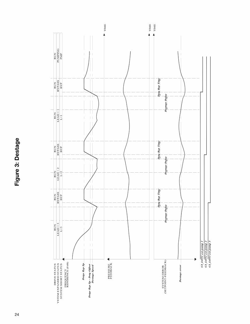
24
Dst
ge B
yp
Sp
DR
IVE
ST
AT
US
TIM
E
YS
TE
M E
XP
AN
DE
D S
TA
TU
SS
YS
TE
M S
HO
RT
ST
AT
US
PU
MP
ING
PM
P
RU
N
Dest
ag
e S
peed CI_
LO
51
ex
t p
um
p 1
FR
EQ
UE
NC
YR
EF
ER
EN
CE
(F
rH)
TIM
E
CI_
LO
52
ex
t p
um
p 2
CI_
LO
53
ex
t p
um
p 3
Dst
ge B
yp
Sp
- D
stg
Off
set
PR
ES
SU
RE
FE
ED
BA
CK
TIM
E
Dest
ag
e e
rro
r
SY
ST
EM
ER
RO
RD
est
ag
e D
ela
yD
est
ag
e D
ela
yD
est
ag
e D
ela
y
Dst
g B
yp
Tim
eD
stg
Byp
Tim
eD
stg
Byp
Tim
e
BY
PA
SS
BY
P
RU
NL
EA
D +
2L
+2
RU
NB
YP
AS
SB
YP
RU
NL
EA
D +
1L
+1
RU
NB
YP
AS
SB
YP
RU
NL
EA
D +
3L
+3
RU
N
(SE
TP
OIN
T-F
EE
DB
AC
K)
Fig
ure
3: D
esta
ge
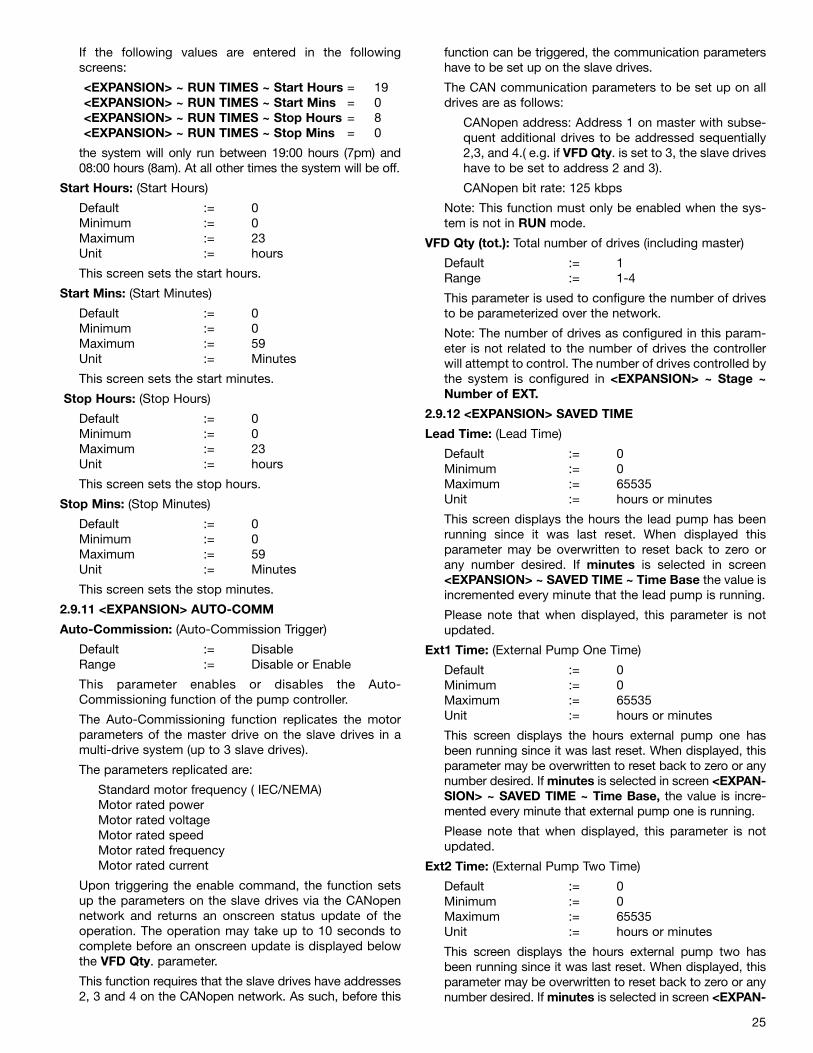
25
If the following values are entered in the followingscreens:
<EXPANSION> ~ RUN TIMES ~ Start Hours = 19<EXPANSION> ~ RUN TIMES ~ Start Mins = 0<EXPANSION> ~ RUN TIMES ~ Stop Hours = 8<EXPANSION> ~ RUN TIMES ~ Stop Mins = 0
the system will only run between 19:00 hours (7pm) and08:00 hours (8am). At all other times the system will be off.
Start Hours: (Start Hours)
Default := 0 Minimum := 0Maximum := 23Unit := hours
This screen sets the start hours.
Start Mins: (Start Minutes)
Default := 0Minimum := 0Maximum := 59Unit := Minutes
This screen sets the start minutes.
Stop Hours: (Stop Hours)
Default := 0Minimum := 0Maximum := 23Unit := hours
This screen sets the stop hours.
Stop Mins: (Stop Minutes)
Default := 0Minimum := 0Maximum := 59Unit := Minutes
This screen sets the stop minutes.
2.9.11 <EXPANSION> AUTO-COMM
Auto-Commission: (Auto-Commission Trigger)
Default := Disable Range := Disable or Enable
This parameter enables or disables the Auto-Commissioning function of the pump controller.
The Auto-Commissioning function replicates the motorparameters of the master drive on the slave drives in amulti-drive system (up to 3 slave drives).
The parameters replicated are:
Standard motor frequency ( IEC/NEMA)Motor rated powerMotor rated voltageMotor rated speed Motor rated frequencyMotor rated current
Upon triggering the enable command, the function setsup the parameters on the slave drives via the CANopennetwork and returns an onscreen status update of theoperation. The operation may take up to 10 seconds tocomplete before an onscreen update is displayed belowthe VFD Qty. parameter.
This function requires that the slave drives have addresses2, 3 and 4 on the CANopen network. As such, before this
function can be triggered, the communication parametershave to be set up on the slave drives.
The CAN communication parameters to be set up on alldrives are as follows:
CANopen address: Address 1 on master with subse-quent additional drives to be addressed sequentially2,3, and 4.( e.g. if VFD Qty. is set to 3, the slave driveshave to be set to address 2 and 3).
CANopen bit rate: 125 kbps
Note: This function must only be enabled when the sys-tem is not in RUN mode.
VFD Qty (tot.): Total number of drives (including master)
Default := 1 Range := 1-4
This parameter is used to configure the number of drivesto be parameterized over the network.
Note: The number of drives as configured in this param-eter is not related to the number of drives the controllerwill attempt to control. The number of drives controlled bythe system is configured in <EXPANSION> ~ Stage ~Number of EXT.
2.9.12 <EXPANSION> SAVED TIME
Lead Time: (Lead Time)
Default := 0 Minimum := 0Maximum := 65535Unit := hours or minutes
This screen displays the hours the lead pump has beenrunning since it was last reset. When displayed thisparameter may be overwritten to reset back to zero orany number desired. If minutes is selected in screen<EXPANSION> ~ SAVED TIME ~ Time Base the value isincremented every minute that the lead pump is running.
Please note that when displayed, this parameter is notupdated.
Ext1 Time: (External Pump One Time)
Default := 0 Minimum := 0Maximum := 65535Unit := hours or minutes
This screen displays the hours external pump one hasbeen running since it was last reset. When displayed, thisparameter may be overwritten to reset back to zero or anynumber desired. If minutes is selected in screen <EXPAN-SION> ~ SAVED TIME ~ Time Base, the value is incre-mented every minute that external pump one is running.
Please note that when displayed, this parameter is notupdated.
Ext2 Time: (External Pump Two Time)
Default := 0 Minimum := 0Maximum := 65535Unit := hours or minutes
This screen displays the hours external pump two hasbeen running since it was last reset. When displayed, thisparameter may be overwritten to reset back to zero or anynumber desired. If minutes is selected in screen <EXPAN-
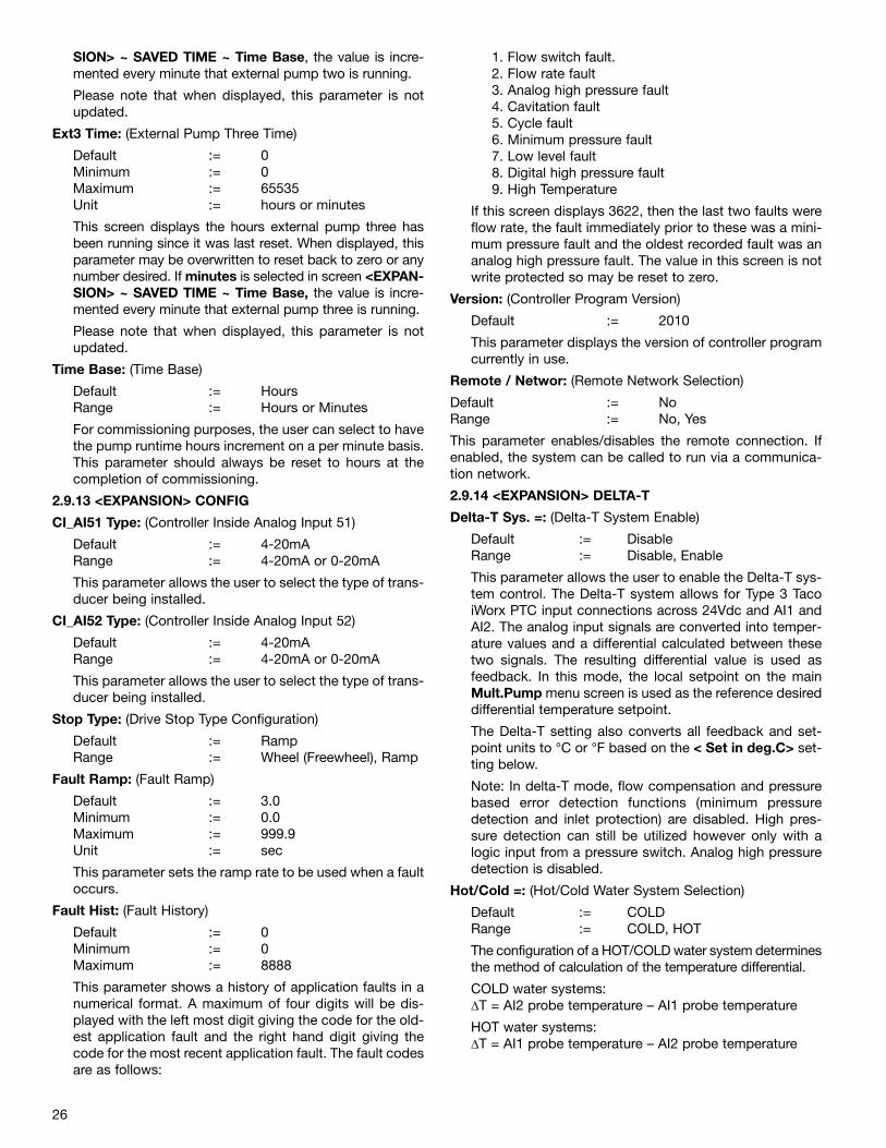
26
SION> ~ SAVED TIME ~ Time Base, the value is incre-mented every minute that external pump two is running.
Please note that when displayed, this parameter is notupdated.
Ext3 Time: (External Pump Three Time)
Default := 0Minimum := 0Maximum := 65535Unit := hours or minutes
This screen displays the hours external pump three hasbeen running since it was last reset. When displayed, thisparameter may be overwritten to reset back to zero or anynumber desired. If minutes is selected in screen <EXPAN-SION> ~ SAVED TIME ~ Time Base, the value is incre-mented every minute that external pump three is running.
Please note that when displayed, this parameter is notupdated.
Time Base: (Time Base)
Default := HoursRange := Hours or Minutes
For commissioning purposes, the user can select to havethe pump runtime hours increment on a per minute basis.This parameter should always be reset to hours at thecompletion of commissioning.
2.9.13 <EXPANSION> CONFIG
CI_AI51 Type: (Controller Inside Analog Input 51)
Default := 4-20mA Range := 4-20mA or 0-20mA
This parameter allows the user to select the type of trans-ducer being installed.
CI_AI52 Type: (Controller Inside Analog Input 52)
Default := 4-20mA Range := 4-20mA or 0-20mA
This parameter allows the user to select the type of trans-ducer being installed.
Stop Type: (Drive Stop Type Configuration)
Default := RampRange := Wheel (Freewheel), Ramp
Fault Ramp: (Fault Ramp)
Default := 3.0 Minimum := 0.0Maximum := 999.9Unit := sec
This parameter sets the ramp rate to be used when a faultoccurs.
Fault Hist: (Fault History)
Default := 0 Minimum := 0Maximum := 8888
This parameter shows a history of application faults in anumerical format. A maximum of four digits will be dis-played with the left most digit giving the code for the old-est application fault and the right hand digit giving thecode for the most recent application fault. The fault codesare as follows:
1. Flow switch fault.2. Flow rate fault3. Analog high pressure fault4. Cavitation fault5. Cycle fault6. Minimum pressure fault7. Low level fault8. Digital high pressure fault9. High Temperature
If this screen displays 3622, then the last two faults wereflow rate, the fault immediately prior to these was a mini-mum pressure fault and the oldest recorded fault was ananalog high pressure fault. The value in this screen is notwrite protected so may be reset to zero.
Version: (Controller Program Version)
Default := 2010
This parameter displays the version of controller programcurrently in use.
Remote / Networ: (Remote Network Selection)
Default := No Range := No, Yes
This parameter enables/disables the remote connection. Ifenabled, the system can be called to run via a communica-tion network.
2.9.14 <EXPANSION> DELTA-T
Delta-T Sys. =: (Delta-T System Enable)
Default := DisableRange := Disable, Enable
This parameter allows the user to enable the Delta-T sys-tem control. The Delta-T system allows for Type 3 TacoiWorx PTC input connections across 24Vdc and AI1 andAI2. The analog input signals are converted into temper-ature values and a differential calculated between thesetwo signals. The resulting differential value is used asfeedback. In this mode, the local setpoint on the mainMult.Pump menu screen is used as the reference desireddifferential temperature setpoint.
The Delta-T setting also converts all feedback and set-point units to °C or °F based on the < Set in deg.C> set-ting below.
Note: In delta-T mode, flow compensation and pressurebased error detection functions (minimum pressuredetection and inlet protection) are disabled. High pres-sure detection can still be utilized however only with alogic input from a pressure switch. Analog high pressuredetection is disabled.
Hot/Cold =: (Hot/Cold Water System Selection)
Default := COLD Range := COLD, HOT
The configuration of a HOT/COLD water system determinesthe method of calculation of the temperature differential.
COLD water systems:∆T = AI2 probe temperature – AI1 probe temperature
HOT water systems:∆T = AI1 probe temperature – AI2 probe temperature
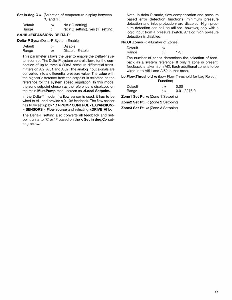
27
Set in deg.C =: (Selection of temperature display between°C and °F)
Default := No (°C setting)Range := No (°C setting), Yes (°F setting)
2.9.15 <EXPANSION> DELTA-P
Delta-P Sys.: (Delta-P System Enable)
Default := DisableRange := Disable, Enable
This parameter allows the user to enable the Delta-P sys-tem control. The Delta-P system control allows for the con-nection of up to three 4-20mA pressure differential trans-mitters on AI2, AI51 and AI52. The analog input signals areconverted into a differential pressure value. The value withthe highest difference from the setpoint is selected as thereference for the system speed regulation. In this mode,the zone setpoint chosen as the reference is displayed onthe main Mult.Pump menu screen as <Local Setpoin>.
In the Delta-T mode, if a flow sensor is used, it has to bewired to AI1 and provide a 0-10V feedback. The flow sensorhas to be set up by 1.14 PUMP CONTROL <EXPANSION>~ SENSORS ~ Flow source and selecting <DRIVE_AI1>.
The Delta-T setting also converts all feedback and set-point units to °C or °F based on the < Set in deg.C> set-ting below.
Note: In delta-P mode, flow compensation and pressurebased error detection functions (minimum pressuredetection and inlet protection) are disabled. High pres-sure detection can still be utilized, however, only with alogic input from a pressure switch. Analog high pressuredetection is disabled.
No.Of Zones =: (Number of Zones)
Default := 1Range := 1-3
The number of zones determines the selection of feed-back as a system reference. If only 1 zone is present,feedback is taken from AI2. Each additional zone is to bewired in to AI51 and AI52 in that order.
Lo.Flow.Threshold =: (Low Flow Threshold for Lag RejectFunction)
Default : = 0.00Range : = 0.0 - 3276.0
Zone1 Set Pt. =: (Zone 1 Setpoint)
Zone2 Set Pt. =: (Zone 2 Setpoint)
Zone3 Set Pt. =: (Zone 3 Setpoint)
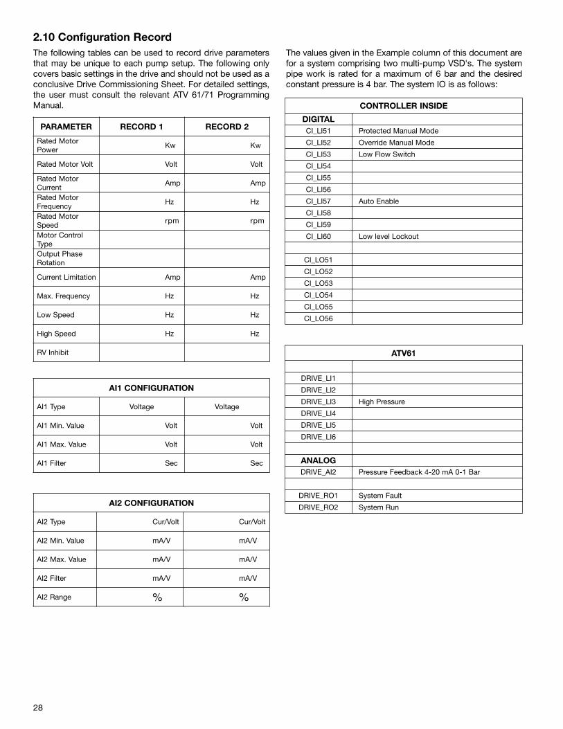
28
2.10 Configuration RecordThe following tables can be used to record drive parametersthat may be unique to each pump setup. The following onlycovers basic settings in the drive and should not be used as aconclusive Drive Commissioning Sheet. For detailed settings,the user must consult the relevant ATV 61/71 ProgrammingManual.
The values given in the Example column of this document arefor a system comprising two multi-pump VSD's. The systempipe work is rated for a maximum of 6 bar and the desiredconstant pressure is 4 bar. The system IO is as follows:
PARAMETER RECORD 1 RECORD 2
Rated MotorPower
Kw Kw
Rated Motor Volt Volt Volt
Rated MotorCurrent
Amp Amp
Rated MotorFrequency
Hz Hz
Rated MotorSpeed
rpm rpm
Motor ControlTypeOutput PhaseRotation
Current Limitation Amp Amp
Max. Frequency Hz Hz
Low Speed Hz Hz
High Speed Hz Hz
RV Inhibit
AI1 CONFIGURATION
AI1 Type Voltage Voltage
AI1 Min. Value Volt Volt
AI1 Max. Value Volt Volt
AI1 Filter Sec Sec
AI2 CONFIGURATION
AI2 Type Cur/Volt Cur/Volt
AI2 Min. Value mA/V mA/V
AI2 Max. Value mA/V mA/V
AI2 Filter mA/V mA/V
AI2 Range % %
CONTROLLER INSIDE
DIGITALCI_LI51 Protected Manual Mode
CI_LI52 Override Manual Mode
CI_LI53 Low Flow Switch
CI_LI54
CI_LI55
CI_LI56
CI_LI57 Auto Enable
CI_LI58
CI_LI59
CI_LI60 Low level Lockout
CI_LO51
CI_LO52
CI_LO53
CI_LO54
CI_LO55
CI_LO56
ATV61
DRIVE_LI1
DRIVE_LI2
DRIVE_LI3 High Pressure
DRIVE_LI4
DRIVE_LI5
DRIVE_LI6
ANALOGDRIVE_AI2 Pressure Feedback 4-20 mA 0-1 Bar
DRIVE_RO1 System Fault
DRIVE_RO2 System Run
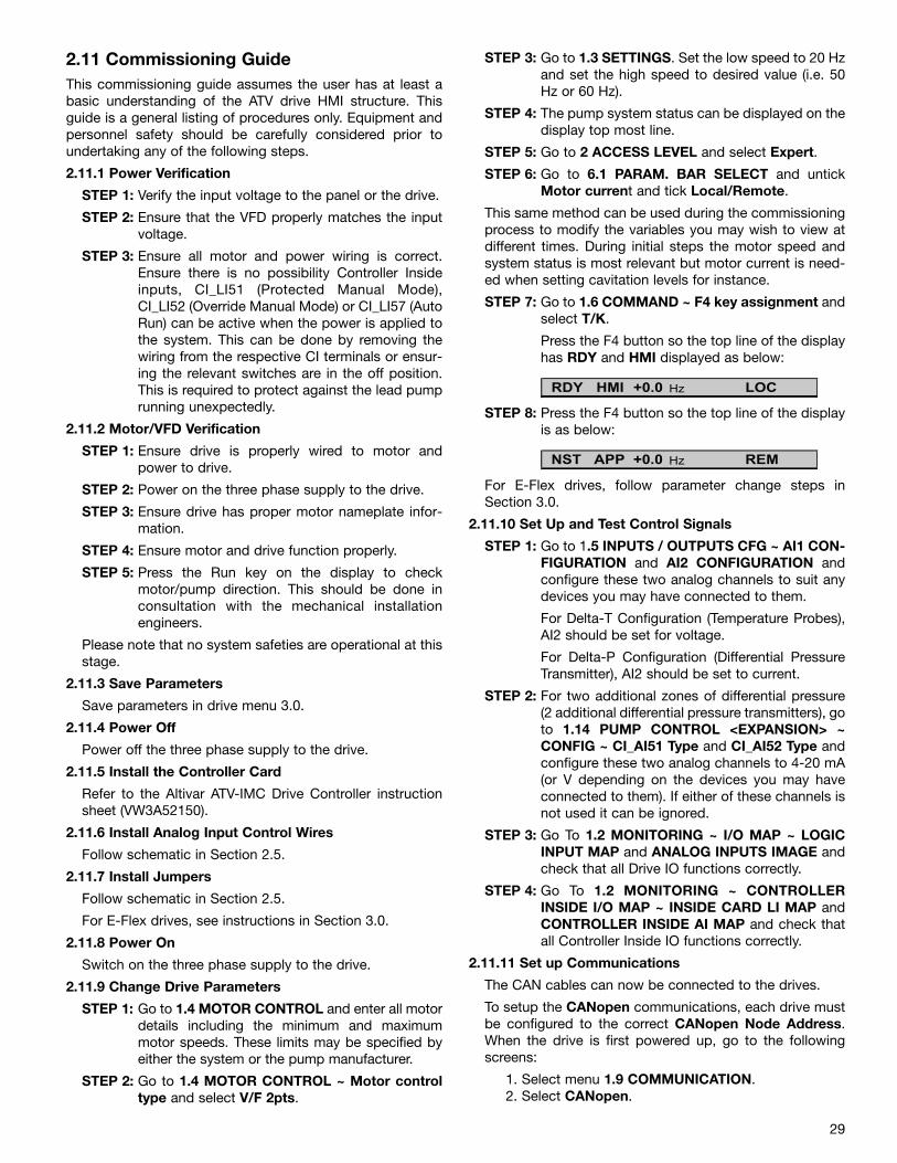
29
2.11 Commissioning GuideThis commissioning guide assumes the user has at least abasic understanding of the ATV drive HMI structure. Thisguide is a general listing of procedures only. Equipment andpersonnel safety should be carefully considered prior toundertaking any of the following steps.
2.11.1 Power Verification
STEP 1: Verify the input voltage to the panel or the drive.
STEP 2: Ensure that the VFD properly matches the inputvoltage.
STEP 3: Ensure all motor and power wiring is correct.Ensure there is no possibility Controller Insideinputs, CI_LI51 (Protected Manual Mode),CI_LI52 (Override Manual Mode) or CI_LI57 (AutoRun) can be active when the power is applied tothe system. This can be done by removing thewiring from the respective CI terminals or ensur-ing the relevant switches are in the off position.This is required to protect against the lead pumprunning unexpectedly.
2.11.2 Motor/VFD Verification
STEP 1: Ensure drive is properly wired to motor andpower to drive.
STEP 2: Power on the three phase supply to the drive.
STEP 3: Ensure drive has proper motor nameplate infor-mation.
STEP 4: Ensure motor and drive function properly.
STEP 5: Press the Run key on the display to checkmotor/pump direction. This should be done inconsultation with the mechanical installationengineers.
Please note that no system safeties are operational at thisstage.
2.11.3 Save Parameters
Save parameters in drive menu 3.0.
2.11.4 Power Off
Power off the three phase supply to the drive.
2.11.5 Install the Controller Card
Refer to the Altivar ATV-IMC Drive Controller instructionsheet (VW3A52150).
2.11.6 Install Analog Input Control Wires
Follow schematic in Section 2.5.
2.11.7 Install Jumpers
Follow schematic in Section 2.5.
For E-Flex drives, see instructions in Section 3.0.
2.11.8 Power On
Switch on the three phase supply to the drive.
2.11.9 Change Drive Parameters
STEP 1: Go to 1.4 MOTOR CONTROL and enter all motordetails including the minimum and maximummotor speeds. These limits may be specified byeither the system or the pump manufacturer.
STEP 2: Go to 1.4 MOTOR CONTROL ~ Motor controltype and select V/F 2pts.
STEP 3: Go to 1.3 SETTINGS. Set the low speed to 20 Hzand set the high speed to desired value (i.e. 50Hz or 60 Hz).
STEP 4: The pump system status can be displayed on thedisplay top most line.
STEP 5: Go to 2 ACCESS LEVEL and select Expert.
STEP 6: Go to 6.1 PARAM. BAR SELECT and untickMotor current and tick Local/Remote.
This same method can be used during the commissioningprocess to modify the variables you may wish to view atdifferent times. During initial steps the motor speed andsystem status is most relevant but motor current is need-ed when setting cavitation levels for instance.
STEP 7: Go to 1.6 COMMAND ~ F4 key assignment andselect T/K.
Press the F4 button so the top line of the displayhas RDY and HMI displayed as below:
STEP 8: Press the F4 button so the top line of the displayis as below:
For E-Flex drives, follow parameter change steps inSection 3.0.
2.11.10 Set Up and Test Control Signals
STEP 1: Go to 1.5 INPUTS / OUTPUTS CFG ~ AI1 CON-FIGURATION and AI2 CONFIGURATION andconfigure these two analog channels to suit anydevices you may have connected to them.
For Delta-T Configuration (Temperature Probes),AI2 should be set for voltage.
For Delta-P Configuration (Differential PressureTransmitter), AI2 should be set to current.
STEP 2: For two additional zones of differential pressure(2 additional differential pressure transmitters), goto 1.14 PUMP CONTROL <EXPANSION> ~CONFIG ~ CI_AI51 Type and CI_AI52 Type andconfigure these two analog channels to 4-20 mA(or V depending on the devices you may haveconnected to them). If either of these channels isnot used it can be ignored.
STEP 3: Go To 1.2 MONITORING ~ I/O MAP ~ LOGICINPUT MAP and ANALOG INPUTS IMAGE andcheck that all Drive IO functions correctly.
STEP 4: Go To 1.2 MONITORING ~ CONTROLLERINSIDE I/O MAP ~ INSIDE CARD LI MAP andCONTROLLER INSIDE AI MAP and check thatall Controller Inside IO functions correctly.
2.11.11 Set up Communications
The CAN cables can now be connected to the drives.
To setup the CANopen communications, each drive mustbe configured to the correct CANopen Node Address.When the drive is first powered up, go to the followingscreens:
1. Select menu 1.9 COMMUNICATION.2. Select CANopen.
RDY HMI +0.0 Hz LOC
NST APP +0.0 Hz REM
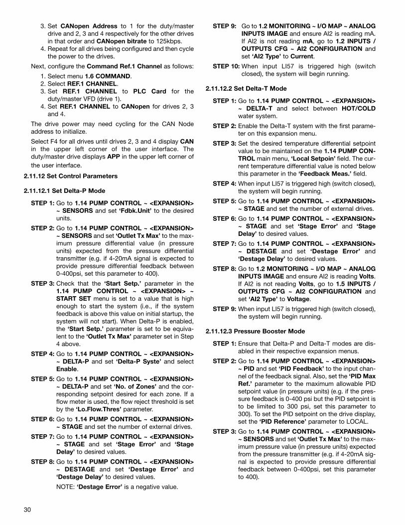
30
3. Set CANopen Address to 1 for the duty/masterdrive and 2, 3 and 4 respectively for the other drivesin that order and CANopen bitrate to 125kbps.
4. Repeat for all drives being configured and then cyclethe power to the drives.
Next, configure the Command Ref.1 Channel as follows:
1. Select menu 1.6 COMMAND.2. Select REF.1 CHANNEL.3. Set REF.1 CHANNEL to PLC Card for the
duty/master VFD (drive 1).4. Set REF.1 CHANNEL to CANopen for drives 2, 3
and 4.
The drive power may need cycling for the CAN Nodeaddress to initialize.
Select F4 for all drives until drives 2, 3 and 4 display CANin the upper left corner of the user interface. Theduty/master drive displays APP in the upper left corner ofthe user interface.
2.11.12 Set Control Parameters
2.11.12.1 Set Delta-P Mode
STEP 1: Go to 1.14 PUMP CONTROL ~ <EXPANSION>~ SENSORS and set ‘Fdbk.Unit’ to the desiredunits.
STEP 2: Go to 1.14 PUMP CONTROL ~ <EXPANSION>~ SENSORS and set ‘Outlet Tx Max’ to the max-imum pressure differential value (in pressureunits) expected from the pressure differentialtransmitter (e.g. if 4-20mA signal is expected toprovide pressure differential feedback between0-400psi, set this parameter to 400).
STEP 3: Check that the ‘Start Setp.’ parameter in the1.14 PUMP CONTROL ~ <EXPANSION> ~START SET menu is set to a value that is highenough to start the system (i.e., if the systemfeedback is above this value on initial startup, thesystem will not start). When Delta-P is enabled,the ‘Start Setp.’ parameter is set to be equiva-lent to the ‘Outlet Tx Max’ parameter set in Step4 above.
STEP 4: Go to 1.14 PUMP CONTROL ~ <EXPANSION>~ DELTA-P and set ‘Delta-P Syste’ and selectEnable.
STEP 5: Go to 1.14 PUMP CONTROL ~ <EXPANSION>~ DELTA-P and set ‘No. of Zones’ and the cor-responding setpoint desired for each zone. If aflow meter is used, the flow reject threshold is setby the ‘Lo.Flow.Thres’ parameter.
STEP 6: Go to 1.14 PUMP CONTROL ~ <EXPANSION>~ STAGE and set the number of external drives.
STEP 7: Go to 1.14 PUMP CONTROL ~ <EXPANSION>~ STAGE and set ‘Stage Error’ and ‘StageDelay’ to desired values.
STEP 8: Go to 1.14 PUMP CONTROL ~ <EXPANSION>~ DESTAGE and set ‘Destage Error’ and‘Destage Delay’ to desired values.
NOTE: ‘Destage Error’ is a negative value.
STEP 9: Go to 1.2 MONITORING ~ I/O MAP ~ ANALOGINPUTS IMAGE and ensure AI2 is reading mA.If AI2 is not reading mA, go to 1.2 INPUTS /OUTPUTS CFG ~ AI2 CONFIGURATION andset ‘AI2 Type’ to Current.
STEP 10: When input LI57 is triggered high (switchclosed), the system will begin running.
2.11.12.2 Set Delta-T Mode
STEP 1: Go to 1.14 PUMP CONTROL ~ <EXPANSION>~ DELTA-T and select between HOT/COLDwater system.
STEP 2: Enable the Delta-T system with the first parame-ter on this expansion menu.
STEP 3: Set the desired temperature differential setpointvalue to be maintained on the 1.14 PUMP CON-TROL main menu, ‘Local Setpoin’ field. The cur-rent temperature differential value is noted belowthis parameter in the ‘Feedback Meas.’ field.
STEP 4: When input LI57 is triggered high (switch closed),the system will begin running.
STEP 5: Go to 1.14 PUMP CONTROL ~ <EXPANSION>~ STAGE and set the number of external drives.
STEP 6: Go to 1.14 PUMP CONTROL ~ <EXPANSION>~ STAGE and set ‘Stage Error’ and ‘StageDelay’ to desired values.
STEP 7: Go to 1.14 PUMP CONTROL ~ <EXPANSION>~ DESTAGE and set ‘Destage Error’ and‘Destage Delay’ to desired values.
STEP 8: Go to 1.2 MONITORING ~ I/O MAP ~ ANALOGINPUTS IMAGE and ensure AI2 is reading Volts.If AI2 is not reading Volts, go to 1.5 INPUTS /OUTPUTS CFG ~ AI2 CONFIGURATION andset ‘AI2 Type’ to Voltage.
STEP 9: When input LI57 is triggered high (switch closed),the system will begin running.
2.11.12.3 Pressure Booster Mode
STEP 1: Ensure that Delta-P and Delta-T modes are dis-abled in their respective expansion menus.
STEP 2: Go to 1.14 PUMP CONTROL ~ <EXPANSION>~ PID and set ‘PID Feedback’ to the input chan-nel of the feedback signal. Also, set the ‘PID MaxRef.’ parameter to the maximum allowable PIDsetpoint value (in pressure units) (e.g. if the pres-sure feedback is 0-400 psi but the PID setpoint isto be limited to 300 psi, set this parameter to300). To set the PID setpoint on the drive display,set the ‘PID Reference’ parameter to LOCAL.
STEP 3: Go to 1.14 PUMP CONTROL ~ <EXPANSION>~ SENSORS and set ‘Outlet Tx Max’ to the max-imum pressure value (in pressure units) expectedfrom the pressure transmitter (e.g. if 4-20mA sig-nal is expected to provide pressure differentialfeedback between 0-400psi, set this parameterto 400).
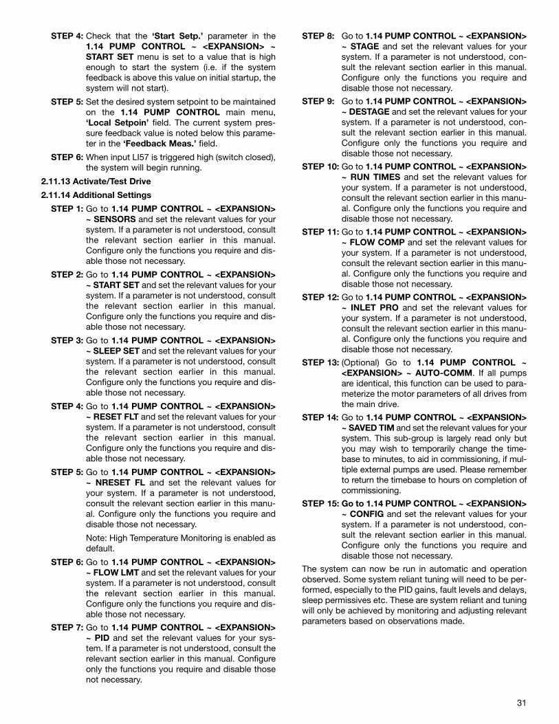
31
STEP 4: Check that the ‘Start Setp.’ parameter in the1.14 PUMP CONTROL ~ <EXPANSION> ~START SET menu is set to a value that is highenough to start the system (i.e. if the systemfeedback is above this value on initial startup, thesystem will not start).
STEP 5: Set the desired system setpoint to be maintainedon the 1.14 PUMP CONTROL main menu,‘Local Setpoin’ field. The current system pres-sure feedback value is noted below this parame-ter in the ‘Feedback Meas.’ field.
STEP 6: When input LI57 is triggered high (switch closed),the system will begin running.
2.11.13 Activate/Test Drive
2.11.14 Additional Settings
STEP 1: Go to 1.14 PUMP CONTROL ~ <EXPANSION>~ SENSORS and set the relevant values for yoursystem. If a parameter is not understood, consultthe relevant section earlier in this manual.Configure only the functions you require and dis-able those not necessary.
STEP 2: Go to 1.14 PUMP CONTROL ~ <EXPANSION>~ START SET and set the relevant values for yoursystem. If a parameter is not understood, consultthe relevant section earlier in this manual.Configure only the functions you require and dis-able those not necessary.
STEP 3: Go to 1.14 PUMP CONTROL ~ <EXPANSION>~ SLEEP SET and set the relevant values for yoursystem. If a parameter is not understood, consultthe relevant section earlier in this manual.Configure only the functions you require and dis-able those not necessary.
STEP 4: Go to 1.14 PUMP CONTROL ~ <EXPANSION>~ RESET FLT and set the relevant values for yoursystem. If a parameter is not understood, consultthe relevant section earlier in this manual.Configure only the functions you require and dis-able those not necessary.
STEP 5: Go to 1.14 PUMP CONTROL ~ <EXPANSION>~ NRESET FL and set the relevant values foryour system. If a parameter is not understood,consult the relevant section earlier in this manu-al. Configure only the functions you require anddisable those not necessary.
Note: High Temperature Monitoring is enabled asdefault.
STEP 6: Go to 1.14 PUMP CONTROL ~ <EXPANSION>~ FLOW LMT and set the relevant values for yoursystem. If a parameter is not understood, consultthe relevant section earlier in this manual.Configure only the functions you require and dis-able those not necessary.
STEP 7: Go to 1.14 PUMP CONTROL ~ <EXPANSION>~ PID and set the relevant values for your sys-tem. If a parameter is not understood, consult therelevant section earlier in this manual. Configureonly the functions you require and disable thosenot necessary.
STEP 8: Go to 1.14 PUMP CONTROL ~ <EXPANSION>~ STAGE and set the relevant values for yoursystem. If a parameter is not understood, con-sult the relevant section earlier in this manual.Configure only the functions you require anddisable those not necessary.
STEP 9: Go to 1.14 PUMP CONTROL ~ <EXPANSION>~ DESTAGE and set the relevant values for yoursystem. If a parameter is not understood, con-sult the relevant section earlier in this manual.Configure only the functions you require anddisable those not necessary.
STEP 10: Go to 1.14 PUMP CONTROL ~ <EXPANSION>~ RUN TIMES and set the relevant values foryour system. If a parameter is not understood,consult the relevant section earlier in this manu-al. Configure only the functions you require anddisable those not necessary.
STEP 11: Go to 1.14 PUMP CONTROL ~ <EXPANSION>~ FLOW COMP and set the relevant values foryour system. If a parameter is not understood,consult the relevant section earlier in this manu-al. Configure only the functions you require anddisable those not necessary.
STEP 12: Go to 1.14 PUMP CONTROL ~ <EXPANSION>~ INLET PRO and set the relevant values foryour system. If a parameter is not understood,consult the relevant section earlier in this manu-al. Configure only the functions you require anddisable those not necessary.
STEP 13: (Optional) Go to 1.14 PUMP CONTROL ~<EXPANSION> ~ AUTO-COMM. If all pumpsare identical, this function can be used to para-meterize the motor parameters of all drives fromthe main drive.
STEP 14: Go to 1.14 PUMP CONTROL ~ <EXPANSION>~ SAVED TIM and set the relevant values for yoursystem. This sub-group is largely read only butyou may wish to temporarily change the time-base to minutes, to aid in commissioning, if mul-tiple external pumps are used. Please rememberto return the timebase to hours on completion ofcommissioning.
STEP 15: Go to 1.14 PUMP CONTROL ~ <EXPANSION>~ CONFIG and set the relevant values for yoursystem. If a parameter is not understood, con-sult the relevant section earlier in this manual.Configure only the functions you require anddisable those not necessary.
The system can now be run in automatic and operationobserved. Some system reliant tuning will need to be per-formed, especially to the PID gains, fault levels and delays,sleep permissives etc. These are system reliant and tuningwill only be achieved by monitoring and adjusting relevantparameters based on observations made.
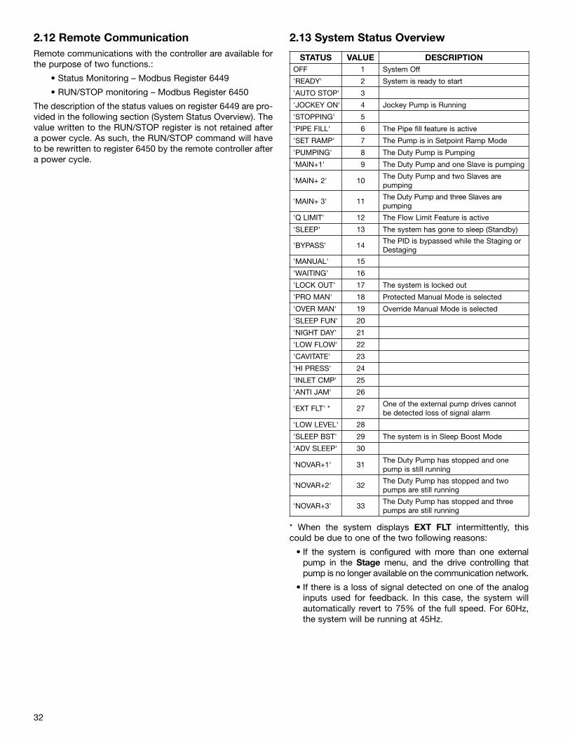
32
2.12 Remote CommunicationRemote communications with the controller are available forthe purpose of two functions.:
• Status Monitoring – Modbus Register 6449
• RUN/STOP monitoring – Modbus Register 6450
The description of the status values on register 6449 are pro-vided in the following section (System Status Overview). Thevalue written to the RUN/STOP register is not retained aftera power cycle. As such, the RUN/STOP command will haveto be rewritten to register 6450 by the remote controller aftera power cycle.
2.13 System Status Overview
STATUS VALUE DESCRIPTIONOFF 1 System Off
'READY' 2 System is ready to start
'AUTO STOP' 3
'JOCKEY ON' 4 Jockey Pump is Running
'STOPPING' 5
'PIPE FILL' 6 The Pipe fill feature is active
'SET RAMP' 7 The Pump is in Setpoint Ramp Mode
'PUMPING' 8 The Duty Pump is Pumping
'MAIN+1' 9 The Duty Pump and one Slave is pumping
'MAIN+ 2' 10The Duty Pump and two Slaves arepumping
'MAIN+ 3' 11The Duty Pump and three Slaves arepumping
'Q LIMIT' 12 The Flow Limit Feature is active
'SLEEP' 13 The system has gone to sleep (Standby)
'BYPASS' 14The PID is bypassed while the Staging orDestaging
'MANUAL' 15
'WAITING' 16
'LOCK OUT' 17 The system is locked out
'PRO MAN' 18 Protected Manual Mode is selected
'OVER MAN' 19 Override Manual Mode is selected
'SLEEP FUN' 20
'NIGHT DAY' 21
'LOW FLOW' 22
'CAVITATE' 23
'HI PRESS' 24
'INLET CMP' 25
'ANTI JAM' 26
'EXT FLT' * 27One of the external pump drives cannotbe detected loss of signal alarm
'LOW LEVEL' 28
'SLEEP BST' 29 The system is in Sleep Boost Mode
'ADV SLEEP' 30
'NOVAR+1' 31The Duty Pump has stopped and onepump is still running
'NOVAR+2' 32The Duty Pump has stopped and twopumps are still running
'NOVAR+3' 33The Duty Pump has stopped and threepumps are still running
* When the system displays EXT FLT intermittently, thiscould be due to one of the two following reasons:
• If the system is configured with more than one externalpump in the Stage menu, and the drive controlling thatpump is no longer available on the communication network.
• If there is a loss of signal detected on one of the analoginputs used for feedback. In this case, the system willautomatically revert to 75% of the full speed. For 60Hz,the system will be running at 45Hz.
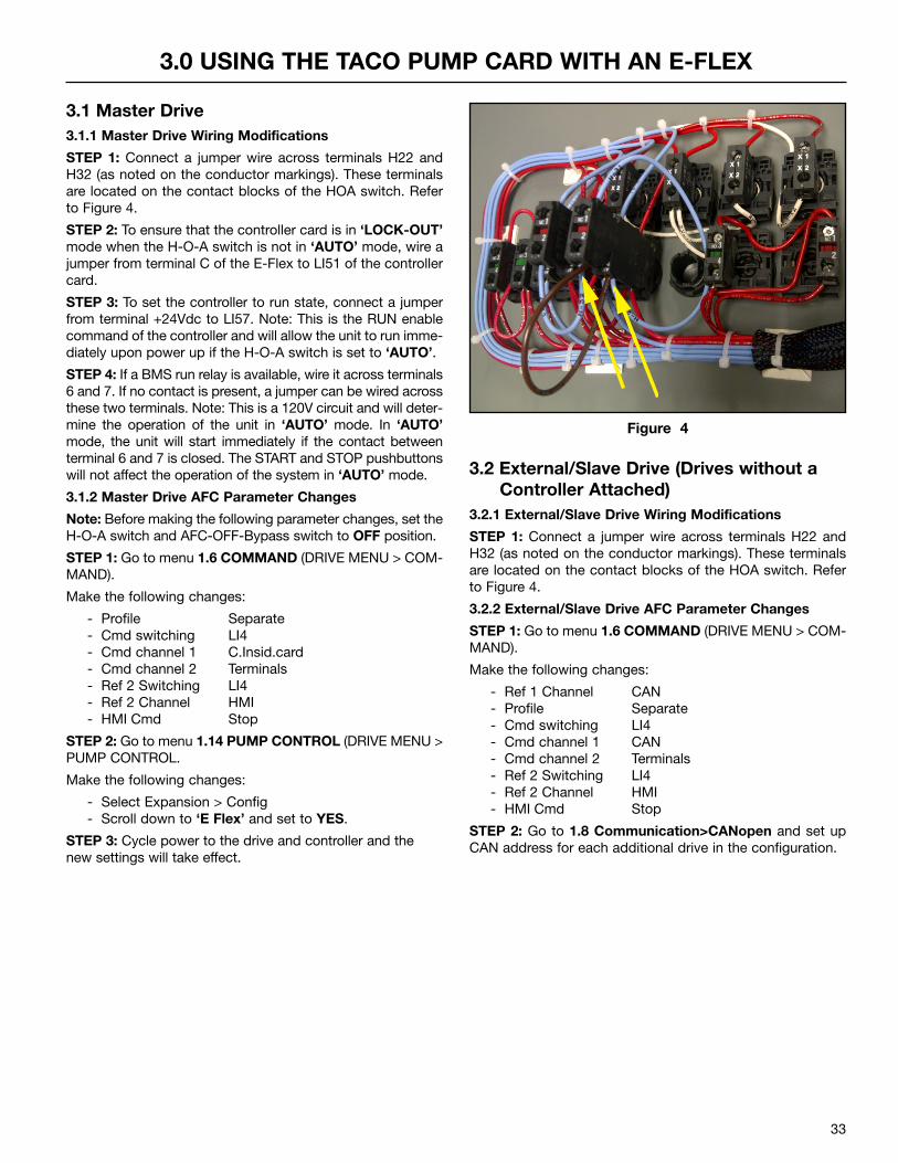
33
3.0 USING THE TACO PUMP CARD WITH AN E-FLEX
3.1 Master Drive3.1.1 Master Drive Wiring Modifications
STEP 1: Connect a jumper wire across terminals H22 andH32 (as noted on the conductor markings). These terminalsare located on the contact blocks of the HOA switch. Referto Figure 4.
STEP 2: To ensure that the controller card is in ‘LOCK-OUT’mode when the H-O-A switch is not in ‘AUTO’ mode, wire ajumper from terminal C of the E-Flex to LI51 of the controllercard.
STEP 3: To set the controller to run state, connect a jumperfrom terminal +24Vdc to LI57. Note: This is the RUN enablecommand of the controller and will allow the unit to run imme-diately upon power up if the H-O-A switch is set to ‘AUTO’.
STEP 4: If a BMS run relay is available, wire it across terminals6 and 7. If no contact is present, a jumper can be wired acrossthese two terminals. Note: This is a 120V circuit and will deter-mine the operation of the unit in ‘AUTO’ mode. In ‘AUTO’mode, the unit will start immediately if the contact betweenterminal 6 and 7 is closed. The START and STOP pushbuttonswill not affect the operation of the system in ‘AUTO’ mode.
3.1.2 Master Drive AFC Parameter Changes
Note: Before making the following parameter changes, set theH-O-A switch and AFC-OFF-Bypass switch to OFF position.
STEP 1: Go to menu 1.6 COMMAND (DRIVE MENU > COM-MAND).
Make the following changes:
- Profile Separate- Cmd switching LI4- Cmd channel 1 C.Insid.card- Cmd channel 2 Terminals- Ref 2 Switching LI4- Ref 2 Channel HMI- HMI Cmd Stop
STEP 2: Go to menu 1.14 PUMP CONTROL (DRIVE MENU >PUMP CONTROL.
Make the following changes:
- Select Expansion > Config- Scroll down to ‘E Flex’ and set to YES.
STEP 3: Cycle power to the drive and controller and thenew settings will take effect.
3.2 External/Slave Drive (Drives without aController Attached)
3.2.1 External/Slave Drive Wiring Modifications
STEP 1: Connect a jumper wire across terminals H22 andH32 (as noted on the conductor markings). These terminalsare located on the contact blocks of the HOA switch. Referto Figure 4.
3.2.2 External/Slave Drive AFC Parameter Changes
STEP 1: Go to menu 1.6 COMMAND (DRIVE MENU > COM-MAND).
Make the following changes:
- Ref 1 Channel CAN- Profile Separate- Cmd switching LI4- Cmd channel 1 CAN- Cmd channel 2 Terminals- Ref 2 Switching LI4- Ref 2 Channel HMI- HMI Cmd Stop
STEP 2: Go to 1.8 Communication>CANopen and set upCAN address for each additional drive in the configuration.
Figure 4
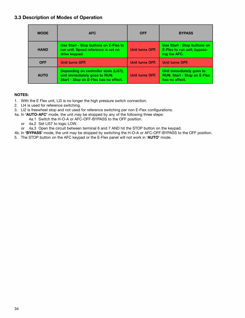
34
3.3 Description of Modes of Operation
MODE AFC OFF BYPASS
HANDUse Start - Stop buttons on E-Flex torun unit. Speed reference is set ondrive keypad.
Unit turns OFF.Use Start - Stop buttons onE-Flex to run unit, bypass-ing the AFC.
OFF Unit turns OFF. Unit turns OFF. Unit turns OFF.
AUTODepending on controller state (LI57),unit immediately goes to RUN.Start - Stop on E-Flex has no effect.
Unit turns OFF.Unit immediately goes toRUN. Start - Stop on E-Flexhas no effect.
NOTES:
1. With the E Flex unit, LI3 is no longer the high pressure switch connection.2. LI4 is used for reference switching.3. LI2 is freewheel stop and not used for reference switching per non E-Flex configurations.4a. In ‘AUTO-AFC’ mode, the unit may be stopped by any of the following three steps:
4a.1 Switch the H-O-A or AFC-OFF-BYPASS to the OFF position.or 4a.2 Set LI57 to logic LOW.or 4a.3 Open the circuit between terminal 6 and 7 AND hit the STOP button on the keypad.
4b. In ‘BYPASS’ mode, the unit may be stopped by switching the H-O-A or AFC-OFF-BYPASS to the OFF position. 5. The STOP button on the AFC keypad or the E-Flex panel will not work in ‘AUTO’ mode.
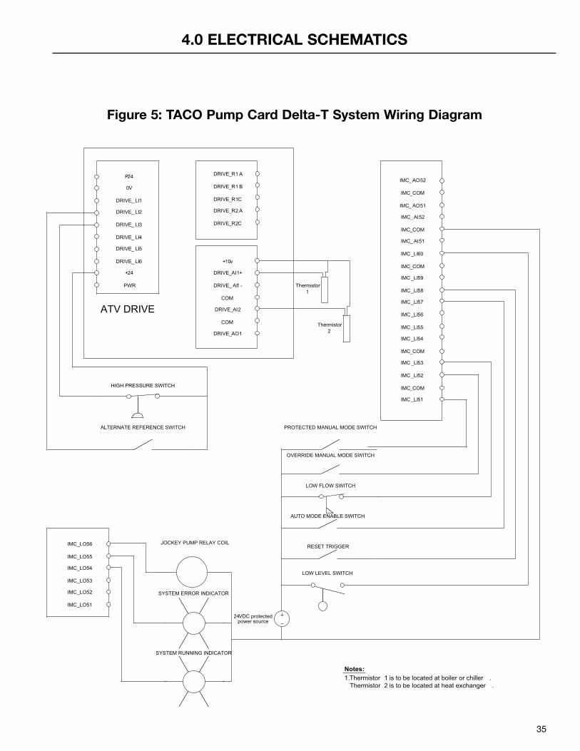
35
4.0 ELECTRICAL SCHEMATICS
PROTECTED MANUAL MODE SWITCH
P24
0V
PWR
DRIVE_ LI1
DRIVE_ LI2
DRIVE_ LI3
DRIVE_ LI4
DRIVE_ LI5
DRIVE_ LI6
+24
DRIVE_R1 A
DRIVE_R1 B
DRIVE_R1C
DRIVE_R2 A
DRIVE_R2C
+10v
DRIVE_AI1+
DRIVE_ AI1 -
COM
DRIVE_AI2
COM
DRIVE_AO1
IMC_ AO52
IMC_COM
IMC _LI58
IMC_ AO51
IMC_ AI52
IMC_COM
IMC_ AI51
IMC _LI60
IMC_COM
IMC _LI59
IMC _LI57
IMC _LI56
IMC _LI55
IMC _LI54
IMC_COM
IMC _LI53
IMC _LI52
IMC_COM
IMC _LI51
ATV DRIVE
LOW FLOW SWITCH
OVERRIDE MANUAL MODE SWITCH
AUTO MODE ENABLE SWITCH
RESET TRIGGER
HIGH PRESSURE SWITCH
ALTERNATE REFERENCE SWITCH
IMC_LO56
IMC_LO55
IMC_LO54
IMC_LO53
IMC_LO52
IMC_LO51
JOCKEY PUMP RELAY COIL
SYSTEM RUNNING INDICATOR
SYSTEM ERROR INDICATOR
24VDC protected power source
LOW LEVEL SWITCH
Thermistor 1
Thermistor 2
Notes:1.Thermistor 1 is to be located at boiler or chiller . Thermistor 2 is to be located at heat exchanger .
Figure 5: TACO Pump Card Delta-T System Wiring Diagram
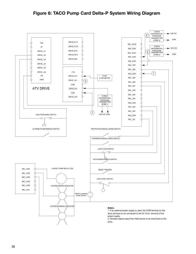
36
PROTECTED MANUAL MODE SWITCH
P24
0V
PWR
DRIVE_ LI1
DRIVE_ LI2
DRIVE_ LI3
DRIVE_ LI4
DRIVE_ LI5
DRIVE_ LI6
+24
DRIVE_R1 A
DRIVE_R1 B
DRIVE_R1C
DRIVE_R2 A
DRIVE_R2C
+10v
DRIVE_AI1+
DRIVE_ AI1 -
COM
DRIVE_AI2
COM
DRIVE_AO1
IMC_ AO52
IMC_COM
IMC _LI58
IMC_ AO51
IMC_ AI52
IMC_COM
IMC_ AI51
IMC _LI60
IMC_COM
IMC _LI59
IMC _LI57
IMC _LI56
IMC _LI55
IMC _LI54
IMC_COM
IMC _LI53
IMC _LI52
IMC_COM
IMC _LI51
ATV DRIVE
LOW FLOW SWITCH
OVERRIDE MANUAL MODE SWITCH
AUTO MODE ENABLE SWITCH
RESET TRIGGER
HIGH PRESSURE SWITCH
ALTERNATE REFERENCE SWITCH
IMC_LO56
IMC_LO55
IMC_LO54
IMC_LO53
IMC_LO52
IMC_LO51
JOCKEY PUMP RELAY COIL
SYSTEM RUNNING INDICATOR
SYSTEM ERROR INDICATOR
24VDC protected power source
LOW LEVEL SWITCH
Notes:1. If an external power supply is used, the COM terminal on the drive will have to be connected to the 0V /Com. terminal of the power supply.2. Denotes signal output from field device to be wired back to the drive.
4-20mA DIFFERENTIAL
PRESSURE TRANSMITTER
(ZONE 1)
+24V DC COM
0-10V FLOW METER
4-20mA DIFFERENTIAL
PRESSURE TRANSMITTER
( ZONE 3)
4-20mA DIFFERENTIAL
PRESSURE TRANSMITTER
( ZONE 2)
+ 24V DC
+24V DC
COM
COM
2
1
1
2
2
Figure 6: TACO Pump Card Delta-P System Wiring Diagram
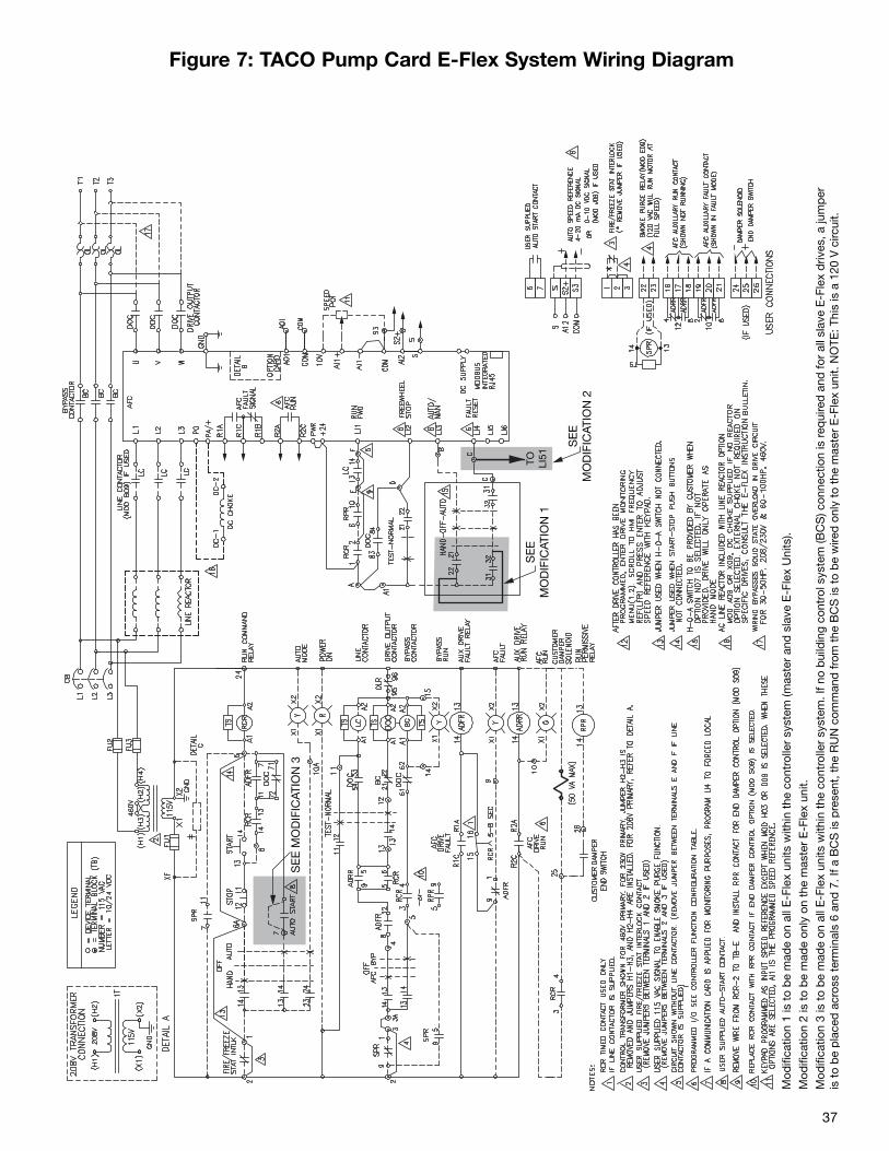
37
Figure 7: TACO Pump Card E-Flex System Wiring Diagram
SE
E M
OD
IFIC
ATIO
N 3
TO LI51
SE
EM
OD
IFIC
ATIO
N 1
SE
EM
OD
IFIC
ATIO
N 2
Mod
ifica
tion
1 is
to
be
mad
e on
all
E-F
lex
units
with
in t
he c
ontr
olle
r sy
stem
(mas
ter
and
sla
ve E
-Fle
x U
nits
).M
odifi
catio
n 2
is t
o b
e m
ade
only
on
the
mas
ter
E-F
lex
unit.
Mod
ifica
tion
3 is
to
be
mad
e on
all
E-F
lex
units
with
in t
he c
ontr
olle
r sy
stem
. If n
o b
uild
ing
cont
rol s
yste
m (B
CS
) con
nect
ion
is r
equi
red
and
for
all s
lave
E-F
lex
driv
es, a
jum
per
is t
o b
e p
lace
d a
cros
s te
rmin
als
6 an
d 7
. If a
BC
S is
pre
sent
, the
RU
N c
omm
and
from
the
BC
S is
to
be
wire
d o
nly
to t
he m
aste
r E
-Fle
x un
it. N
OTE
: Thi
s is
a 1
20 V
circ
uit.
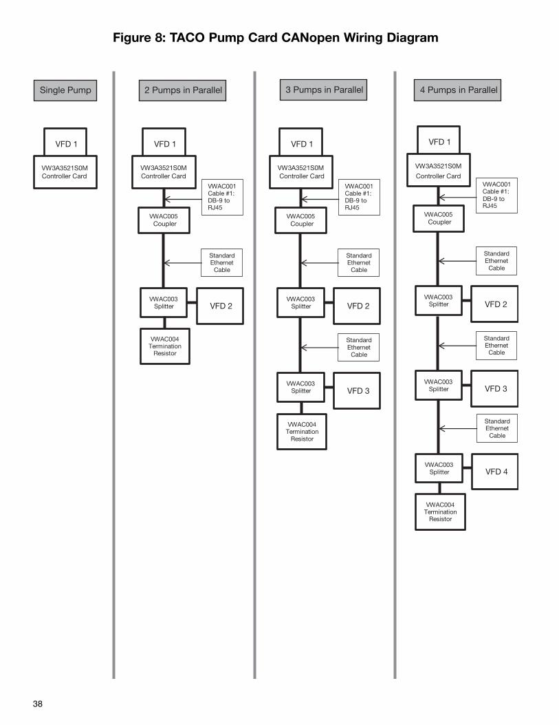
38
Figure 8: TACO Pump Card CANopen Wiring Diagram
VFD 1
VW3A3521S0M
VWAC005Coupler
VWAC001Cable #1:
RJ45
Standard Ethernet
Cable
VFD 2VWAC003
Splitter
Standard Ethernet
Cable
VFD 3VWAC003
Splitter
Standard Ethernet
Cable
VFD 4VWAC003
Splitter
VWAC004Termination
Resistor
VFD 1
VW3A3521S0MController Card
VFD 1
VW3A3521S0M
VWAC005Coupler
VWAC001Cable #1: DB-9 toRJ45
Standard Ethernet
Cable
VFD 2VWAC003
Splitter
VWAC004Termination
Resistor
VFD 1
VW3A3521S0M
VWAC005Coupler
VWAC001Cable #1:
RJ45
Standard Ethernet
Cable
VFD 2VWAC003
Splitter
Standard Ethernet
Cable
VFD 3VWAC003
Splitter
VWAC004Termination
Resistor
2 Pumps in Parallel Single Pump 3 Pumps in Parallel 4 Pumps in Parallel
Controller Card
DB-9 to DB-9 to
Controller Card Controller Card
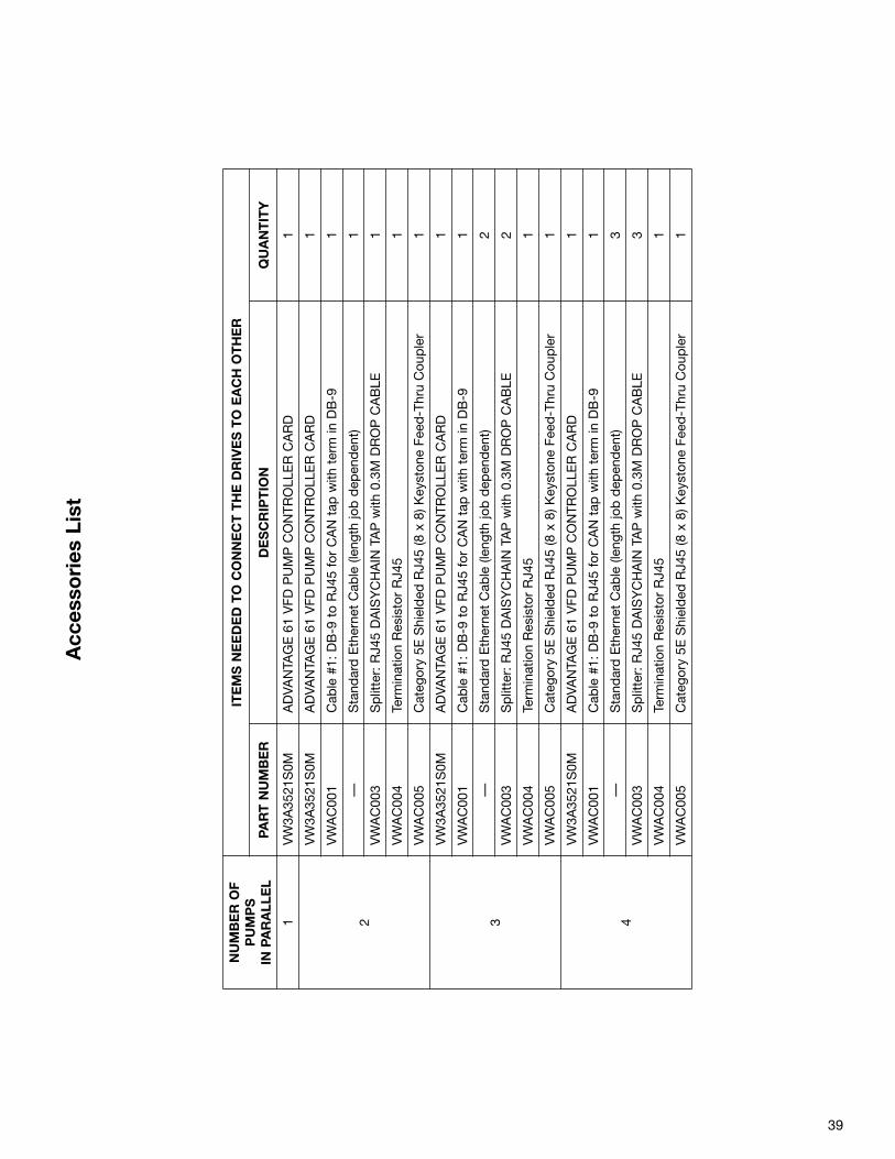
39
Acc
esso
ries
Lis
t
NU
MB
ER
OF
PU
MP
SIN
PA
RA
LLE
L
ITE
MS
NE
ED
ED
TO
CO
NN
EC
T T
HE
DR
IVE
S T
O E
AC
H O
TH
ER
PAR
T N
UM
BE
RD
ES
CR
IPT
ION
QU
AN
TIT
Y
1VW3A
3521
S0M
ADVA
NTA
GE 61 VFD
PUMP C
ONTR
OLL
ER C
ARD
1
2
VW3A
3521
S0M
ADVA
NTA
GE 61 VFD
PUMP C
ONTR
OLL
ER C
ARD
1
VWAC00
1Cab
le #1: D
B-9 to RJ4
5 for CAN tap
with
term in
DB-9
1
—Stand
ard Etherne
t Cab
le (len
gth job dep
enden
t)1
VWAC00
3Splitter: RJ4
5 DAISYCHAIN TAP w
ith 0.3M D
ROP C
ABLE
1
VWAC00
4Term
ination Res
istor RJ4
51
VWAC00
5Categ
ory 5E
Shielded
RJ4
5 (8 x 8) K
eyston
e Fe
ed-Thru Cou
pler
1
3
VW3A
3521
S0M
ADVA
NTA
GE 61 VFD
PUMP C
ONTR
OLL
ER C
ARD
1
VWAC00
1Cab
le #1: D
B-9 to RJ4
5 for CAN tap
with
term in
DB-9
1
—Stand
ard Etherne
t Cab
le (len
gth job dep
enden
t)2
VWAC00
3Splitter: RJ4
5 DAISYCHAIN TAP w
ith 0.3M D
ROP C
ABLE
2
VWAC00
4Term
ination Res
istor RJ4
51
VWAC00
5Categ
ory 5E
Shielded
RJ4
5 (8 x 8) K
eyston
e Fe
ed-Thru Cou
pler
1
4
VW3A
3521
S0M
ADVA
NTA
GE 61 VFD
PUMP C
ONTR
OLL
ER C
ARD
1
VWAC00
1Cab
le #1: D
B-9 to RJ4
5 for CAN tap
with
term in
DB-9
1
—Stand
ard Etherne
t Cab
le (len
gth job dep
enden
t)3
VWAC00
3Splitter: RJ4
5 DAISYCHAIN TAP w
ith 0.3M D
ROP C
ABLE
3
VWAC00
4Term
ination Res
istor RJ4
51
VWAC00
5Categ
ory 5E
Shielded
RJ4
5 (8 x 8) K
eyston
e Fe
ed-Thru Cou
pler
1

Do it Once. Do it Right.®
TACO, INC., 1160 Cranston Street, Cranston, RI 02920 Telephone: (401) 942-8000 FAX: (401) 942-2360.TACO (Canada), Ltd., 8450 Lawson Road, Unit #3, Milton, Ontario L9T 0J8. Telephone: 905/564-9422. FAX: 905/564-9436.
Visit our web site at: http://www.taco-hvac.com
Printed in USA
Copyright 2012
TACO, Inc.