Embed Size (px)
Citation preview

U.S. Department
of Transportation
Federal Aviation
Administration
Advisory Circular
Subject: Standardized Method of Reporting
Airport Pavement Strength - PCN
Date: 8/14/2014
Initiated By: AAS-100
AC No: 150/5335-5C
1 Purpose.
This advisory circular (AC) provides guidance for—
Using the standardized International Civil Aviation Organization (ICAO) method to
report airport runway, taxiway, and apron pavement strength. ICAO requires
member states to report aerodrome-related aeronautical data, including pavement
strength. The standardized method, known as the Aircraft Classification Number –
Pavement Classification Number (ACN-PCN) method, has been developed and
adopted as an international standard and has facilitated the exchange of pavement
strength rating information.
The AC provides guidance for use of the standardized method of reporting
pavement strength, which applies only to pavements with bearing strengths of
12,500 pounds (5 700 kg) or greater. The method of reporting pavement strength
for pavements of less than 12,500 pounds (5 700 kg) bearing strength remains
unchanged.
Reporting changes to airport data that is generally published on Federal Aviation
Administration (FAA) Form 5010, Airport Master Record. The data elements
associated with Gross Weight (Data Elements 35 through 38) and Pavement
Classification Number (Data Element 39) are affected.
2 Cancellation.
This AC cancels AC 150/5335-5B, Standardized Method of Reporting Airport
Pavement Strength – PCN, dated August 26, 2011.
3 Application.
The FAA recommends the guidelines and specifications in this AC for reporting airport
pavement strength using the standardized method. Use of this AC is mandatory for all
projects funded with Federal grant monies through the Airport Improvement Program
(AIP) or with revenue from the Passenger Facility Charge (PFC) Program. See Grant

08/14/14 AC 150/5335-5C
ii
Assurance No. 34, “Policies, Standards, and Specifications,” and PFC Assurance No. 9,
“Standards and Specifications.”
4 Effective Date.
The FAA recommends the guidelines and specifications in this AC for reporting
airport pavement strength using the standardized method for all paved runways,
taxiways, and aprons at all airports.
One year after the implementation of this AC, the FAA requires all public-use paved
runways at all Part 14 CFR 139 certificated airports be assigned gross weight and
PCN data.
Upon completion of projects funded with Federal grant monies through the Airport
Improvement Program (AIP) or with revenue from the Passenger Facility Charge
(PFC) program, the airport will update Form 5010 data elements associated with
Gross Weight and Pavement Classification Number.
5 Principal Changes.
The AC includes the following principal changes:
Updates the Effective Date paragraph above for public-use paved runways at
nonprimary commercial service airports serving air carrier aircraft. Clarifies that
upon completing paving projects that receive AIP or PFC funds, the airport will
update the 5010 form.
Updates the Application paragraph above to clarify that this AC applies to all
runways that have or will receive AIP or PFC funding.
Clarifies in Chapter 3 that COMFAA calculates ACN using ICAO procedures but
calculates PCN using the procedures in this AC.
Clarifies Using Aircraft Method to Determine PCN in paragraph 4.3.
Clarifies the subgrade support category requirement in paragraph 4.4, Technical
Evaluation Method to Determine PCN.
Adds a note to Table A-1, Standard P/TC Ratio Summary.
Updates Appendix C and particularly Section C.6, Technical Evaluation Examples
for Flexible Pavements, and Section C.7, Technical Evaluation Examples for Rigid
Pavements, with easier to follow examples and to comply with the current version
of COMFAA (updated in 2012), 2012), the software program used for airport
pavement thickness and strength evaluations, and the new COMFAA support
spreadsheet (dated 11/21/2012).
Updates Appendix D to conform to the current version of COMFAA.
Makes editorial corrections and clarifications throughout, including adopting a new
paragraph numbering system.

08/14/14 AC 150/5335-5C
iii
6 Related Reading Material.
The publications listed in Appendix G provide further information on the development
and use of the ACN-PCN method.
Michael J. O’Donnell
Director, Office of Airport Safety and Standards

08/14/14 AC 150/5335-5C
iv
Page Intentionally Blank

08/14/14 AC 150/5335-5C
CONTENTS
Paragraph Page
v
CHAPTER 1. INTRODUCTION ................................................................................... 1-1
1.1 Background. ................................................................................................................ 1-1
1.2 Development of a Standardized Method. ................................................................. 1-1
1.3 Application................................................................................................................... 1-1
1.4 Limitations of the ACN-PCN System. ....................................................................... 1-2
CHAPTER 2. DETERMINATION OF AIRCRAFT CLASSIFICATION NUMBER ........ 2-1
2.1 Determination of the ACN. ........................................................................................ 2-1
2.2 Subgrade Category. .................................................................................................... 2-1
2.3 Operational Frequency. .............................................................................................. 2-1
2.4 Rigid Pavement ACN. ................................................................................................. 2-2
2.5 Flexible Pavement ACN. ............................................................................................ 2-2
2.6 ACN Calculation. ........................................................................................................ 2-2
2.7 Variables Involved in Determination of ACN Values. ............................................ 2-2
CHAPTER 3. DETERMINATION OF ACN-PCN VALUES USING COMFAA ............. 3-1
3.1 Availability of COMFAA Software Application. ..................................................... 3-1
3.2 Origin of the COMFAA Program. ............................................................................ 3-1
3.3 COMFAA Program. ................................................................................................... 3-1
3.4 Internal Aircraft Library. .......................................................................................... 3-2
3.5 External Aircraft Library. ......................................................................................... 3-2
3.6 Using the COMFAA Program. .................................................................................. 3-3
CHAPTER 4. DETERMINATION OF PCN NUMERICAL VALUE ............................... 4-1
4.1 PCN Concept. .............................................................................................................. 4-1
4.2 Determination of Numerical PCN Value. ................................................................. 4-1
4.3 Using Aircraft Method to Determine PCN. .............................................................. 4-1
4.4 Technical Evaluation Method to Determine PCN. .................................................. 4-3
4.5 Limitations of the PCN. .............................................................................................. 4-5
4.6 Reporting the PCN. ..................................................................................................... 4-5
APPENDIX A. EQUIVALENT TRAFFIC ..................................................................... A-1
APPENDIX B. TECHNICAL EVALUATION METHOD—EVALUATION PAVEMENT PROPERTIES DETERMINATION .................................................... B-1

08/14/14 AC 150/5335-5C
CONTENTS (CONTINUED)
Paragraph Page
vi
APPENDIX C. PCN DETERMINATION EXAMPLES ................................................. C-1
APPENDIX D. PAVEMENT OVERLOAD EVALUATION BY THE ACN-PCN SYSTEM ................................................................................................................ D-1
APPENDIX E. REPORTING CHANGES TO CERTAIN AIRPORT RUNWAY DATA ELEMENTS ................................................................................................. E-1
APPENDIX F. MAXIMUM AIRCRAFT GROSS WEIGHT TABLES FOR FAA FORM 5010 REPORTING BASED ON PCN DETERMINATION ........................... F-1
APPENDIX G. RELATED READING MATERIAL ....................................................... F-6
LIST OF FIGURES
Figure 3-1. Computational Modes of the COMFAA Program .................................................... 3-4
Figure 3-2. Operation of the COMFAA Program in ACN Mode ................................................ 3-5
Figure 3-3. Operation of the COMFAA Program in PCN Batch Mode ...................................... 3-6
Figure 4-1. Operation of COMFAA ACN Only Program, Version in Batch Mode .................... 4-2
Figure 4-2. COMFAA Program, ACN Only Version in Batch Mode ......................................... 4-3
Figure A-1. Traffic Load Distribution Patterns .......................................................................... A-2
Figure B-1. Flexible Pavement Stabilized Base Layer(s) Equivalency Discussion (FAA
CBR method) .......................................................................................................................B-5
Figure B-2. Flexible Pavement Stabilized Base Layer(s) Equivalency Discussion
(Continued) (FAA CBR method) .........................................................................................B-6
Figure B-3. Rigid Pavement Stabilized Subbase Layer(s) Discussion (FAA Westergaard
method) ................................................................................................................................B-7
Figure B-4. Rigid Pavement Stabilized Subbase Layer(s) Discussion (Continued) (FAA
Westergaard method) ...........................................................................................................B-8
Figure B-5. Subbase Layer Effect on Subgrade Support, k, for Rigid Pavement (FAA
Westergaard method) ...........................................................................................................B-9
Figure B-6. Stabilized Subbase Layer Effect on Subgrade Support, k, for Rigid Pavement
(FAA Westergaard method) ...............................................................................................B-10
Figure B-7. Flexible Pavement quivalency to Rigid Pavement (FAA Westergaard method) ...B-11
Figure C-1. Example of COMFAA ACN Batch Results .............................................................C-2
Figure C-2. Flexible Layer Equivalency Spreadsheet to Support COMFAA .............................C-6
Figure C-3. Rigid Layer Equivalency Spreadsheet to Support COMFAA. .................................C-7
Figure C-4. Screen Shot of PCN Worksheet in COMFAA Support Spreadsheet for
Computing Equivalent Pavement Structure in Flexible Example 1 ..................................C-12
Figure C-5. Detailed COMFAA Batch PCN Output – Flexible Example 1 ..............................C-13
Figure C-6. Detailed COMFAA Batch PCN Output – Flexible Example 2 ..............................C-16

08/14/14 AC 150/5335-5C
CONTENTS (CONTINUED)
Paragraph Page
vii
Figure C-7. Detailed COMFAA Batch PCN Output – Flexible Example 2, Computed Using
the Traffic Mix from Example 1 and Modified P/TC Ratio ..............................................C-18
Figure C-8. Detailed COMFAA Batch PCN Output – Flexible Example 3 ..............................C-20
Figure C-9. Screen Shot of Flexible PCN Tab in COMFAA Support Spreadsheet for
Computing Equivalent Pavement Structure in Flexible Example 4. The structure is the
same as Example 1, but with a 2-inch HMA overlay, for a total P-401 thickness of 7
inches. ................................................................................................................................C-21
Figure C-10. Detailed COMFAA Batch PCN Output – Flexible Example 4 (unadjusted) .......C-22
Figure C-11. Detailed COMFAA Batch PCN Output – Flexible Example 4 (with
adjustment to P/TC ratio to force Total CDF = 0.15) ........................................................C-24
Figure C-12. Screen Sot of Rigid PCN Tab in COMFAA Support Spreadsheet for
Computing Equivalent Pavement Structure in Rigid Example 1 .......................................C-29
Figure C-13. Screen Shot of COMFAA Main Screen Showing the Required Inputs for
Rigid Example 1 ................................................................................................................C-30
Figure C-14. Detailed COMFAA Batch PCN Output – Rigid Example 1 ................................C-31
Figure C-15. Screen Shot of Rigid PCN Tab in COMFAA Support Spreadsheet for
Computing Equivalent Pavement Structure in Rigid Example 2 .......................................C-34
Figure C-16. Detailed COMFAA Batch PCN Output – Rigid Example 2 ................................C-35
Figure C-17. Detailed COMFAA Batch PCN Output – Rigid Example 3 ................................C-38
Figure C-18. Screen Shot of Rigid PCN Tab in COMFAA Support Spreadsheet for
Computing Equivalent Pavement Structure in Rigid Example 4 .......................................C-40
Figure C-19. Detailed COMFAA Batch PCN Output – Rigid Example 4 (unadjusted) ...........C-41
Figure C-20. Detailed COMFAA Batch PCN Output – Rigid Example 4 (with adjustment
to P/TC ratio to force Total CDF = 0.15) ...........................................................................C-43
Figure D-1. CDF-PCN Results for the B-747-100 – Flexible Pavement Overload Option
One ...................................................................................................................................... D-3
Figure D-2. COMFAA Batch ACN Results – Flexible Pavement Overload Option One .......... D-3
Figure D-3. COMFAA Batch PCN Results – Flexible Pavement Overload Option One .......... D-4
Figure D-4. COMFAA PCN Results – Flexible Pavement Overload Option Two .................... D-4
Figure D-5. CDF-PCN Results – Flexible Pavement Overload Option Three ........................... D-5
Figure D-6. CDF-PCN Results for the B-747-400 – Rigid Pavement Overload Option One .... D-6
Figure D-7. COMFAA Batch ACN Results – Rigid Pavement Overload Option One .............. D-6
Figure D-8. COMFAA PCN Results – Rigid Pavement Overload Option One ......................... D-7
Figure D-9. COMFAA PCN Results –Rigid Pavement Overload Option Two ......................... D-7
Figure D-10. COMFAA PCN Results – Rigid Pavement Overload Option Three .................... D-8
LIST OF TABLES
Table 2-1. Standard Subgrade Support Conditions for Rigid Pavement ACN Calculation ........ 2-1
Table 2-2. Standard Subgrade Support Conditions for Flexible Pavement ACN Calculation .... 2-1

08/14/14 AC 150/5335-5C
CONTENTS (CONTINUED)
Paragraph Page
viii
Table 4-1. Pavement Codes for Reporting PCN .......................................................................... 4-5
Table 4-2. Tire Pressure Codes for Reporting PCN .................................................................... 4-7
Table A-1. Standard P/TC Ratio Summary (see Note) ............................................................... A-3
Table B-1. FAA Flexible Pavement Layer Equivalency Factor Range .......................................B-2
Table B-2. FAA Rigid Pavement Subbase Effect on Foundation k Value ..................................B-3
Table C-1. Using Aircraft and Traffic for a Flexible Pavement ..................................................C-4
Table C-2. Using Aircraft and Traffic for a Rigid Pavement ......................................................C-5
Table C-3. Excerpt from COMFAA PCN Batch Results File for Flexible Pavement ................C-8
Table C-4. Conversion to Equivalent Pavement Structure in Flexible Example 1 ....................C-12
Table C-5. Input Traffic Data for Rigid Example 1 ...................................................................C-15
Table C-6. Input Traffic Data for Rigid Example 1 ...................................................................C-27
Table C-7. Conversion to Equivalent Pavement Structure in Rigid Example 1. .......................C-28
Table C-8. Input Traffic Data for Rigid Example 4 ...................................................................C-39
Table E-1. Flexible ACN Data Used to Establish Allowable Gross Weight ............................... E-3
Table E-2. Rigid ACN Data Used to Establish Allowable Gross Weight ................................... E-4
Table E-3. Excerpt From Listing of Maximum Gross Weight Data............................................ E-5
Table F-1. Subgrade Strength Category A ................................................................................... F-1
Table F-2. Subgrade Strength Category B ................................................................................... F-2
Table F-3. Subgrade Strength Category C ................................................................................... F-4
Table F-4. Subgrade Strength Category D ................................................................................... F-5

08/14/14 AC 150/5335-5C
1-1
CHAPTER 1. INTRODUCTION
1.1 Background.
The United States is a contracting state of the International Civil Aviation Organization
(ICAO) and, under 47 USC §40105(b), will act consistently with the obligations of the
United States Government under an international agreement. Annex 14 to the
Convention of International Civil Aviation, Aerodromes, contains a standard that
requires member states to publish information on the strengths of all public airport
pavements in its own Aeronautical Information Publication. The FAA reports
pavement strength information to the National Airspace System Resources (NASR)
database and publishes pavement strength information in the Airport Master Record
(Form 5010) and the Airport/Facility Directory (AFD).
1.2 Development of a Standardized Method.
In 1977, ICAO established a Study Group to develop a single international method of
reporting pavement strengths. The study group developed, and ICAO adopted, the
Aircraft Classification Number - Pavement Classification Number (ACN-PCN) method.
Using this method, it is possible to express the effect of an individual aircraft on
different pavements with a single unique number that varies according to aircraft weight
and configuration (e.g. tire pressure, gear geometry, etc.), pavement type, and subgrade
strength. This number is the Aircraft Classification Number (ACN). Conversely, the
load-carrying capacity of a pavement can be expressed by a single unique number,
without specifying a particular aircraft or detailed information about the pavement
structure. This number is the Pavement Classification Number (PCN).
1.2.1 Definition of ACN.
ACN is a number that expresses the relative effect of an aircraft at a given configuration
on a pavement structure for a specified standard subgrade strength.
1.2.2 Definition of PCN.
PCN is a number that expresses the load-carrying capacity of a pavement for
unrestricted operations.
1.2.3 System Methodology.
The ACN-PCN system is structured so a pavement with a particular PCN value can
support an aircraft that has an ACN value equal to or less than the pavement’s PCN
value. This is possible because ACN and PCN values are computed using the same
technical basis.
1.3 Application.
The use of the standardized method of reporting pavement strength applies only to
pavements with bearing strengths of 12,500 pounds (5 700 kg) or greater. The method
of reporting pavement strength for pavements of less than 12,500 pounds (5 700 kg)
bearing strength remains unchanged.

08/14/14 AC 150/5335-5C
1-2
1.4 Limitations of the ACN-PCN System.
The ACN-PCN system is only intended as a method that airport operators can use to
evaluate acceptable operations of aircraft. It is not intended as a pavement design or
pavement evaluation procedure, nor does it restrict the methodology used to design or
evaluate a pavement structure.

08/14/14 AC 150/5335-5C
2-1
CHAPTER 2. DETERMINATION OF AIRCRAFT CLASSIFICATION NUMBER
2.1 Determination of the ACN.
The aircraft manufacturer provides the official computation of an ACN value.
Computation of the ACN requires detailed information on the operational
characteristics of the aircraft, such as maximum aft center of gravity, maximum ramp
weight, wheel spacing, tire pressure, and other factors.
2.2 Subgrade Category.
The ACN-PCN method adopts four standard levels of subgrade strength for rigid
pavements and four levels of subgrade strength for flexible pavements. These standard
support conditions are used to represent a range of subgrade conditions as shown in
Tables 2-1 and 2-2.
Table 2-1. Standard Subgrade Support Conditions for Rigid Pavement ACN Calculation
Subgrade
Strength
Category
Subgrade Support
k-Value
pci (MN/m3)
Represents
pci (MN/m3)
Code
Designation
High 552.6 (150) k ≥ 442 (≥120) A
Medium 294.7 (80) 221<k<442 (60<k<120) B
Low 147.4 (40) 92<k≤221 (25<k≤60) C
Ultra Low 73.7 (20) k≤92 (≤25) D
Table 2-2. Standard Subgrade Support Conditions for Flexible Pavement ACN Calculation
Subgrade
Strength
Category
Subgrade Support
CBR-Value Represents
Code
Designation
High 15 CBR ≥ 13 A
Medium 10 8<CBR<13 B
Low 6 4<CBR≤8 C
Ultra Low 3 CBR≤4 D
2.3 Operational Frequency.
Operational frequency is defined in terms of coverages that represent a full-load
application on a point in the pavement. Coverages must not be confused with other
common terminology used to reference movement of aircraft. As an aircraft moves
along a pavement section it seldom travels in a perfectly straight path or along the exact

08/14/14 AC 150/5335-5C
2-2
same path as before. This movement is known as aircraft wander and is assumed to be
modeled by a statistically normal distribution. As the aircraft moves along a taxiway or
runway, it may take several trips or passes along the pavement for a specific point on
the pavement to receive a full-load application. It is easy to observe the number of
passes an aircraft may make on a given pavement, but the number of coverages must be
mathematically derived based upon the established pass-to-coverage ratio for each
aircraft.
2.4 Rigid Pavement ACN.
For rigid pavements, the aircraft landing gear flotation requirements are determined by
the Westergaard solution for a loaded elastic plate on a Winkler foundation (interior
load case), assuming a concrete working stress of 399 psi (2.75 MPa).
2.5 Flexible Pavement ACN.
For flexible pavements, aircraft landing gear flotation requirements are determined by
the California Bearing Ratio (CBR) method for each subgrade support category. The
CBR method employs a Boussinesq solution for stresses and displacements in a
homogeneous, isotropic elastic half-space.
2.6 ACN Calculation.
Using the parameters defined for each type of pavement section, a mathematically
derived single wheel load is calculated to define the landing gear/pavement interaction.
The derived single wheel load implies equal stress to the pavement structure and
eliminates the need to specify pavement thickness for comparative purposes. This is
achieved by equating the thickness derived for a given aircraft landing gear to the
thickness derived for a single wheel load at a standard tire pressure of 181 psi (1.25
MPa). The ACN is defined as two times the derived single wheel load (expressed in
thousands of kilograms).
2.7 Variables Involved in Determination of ACN Values.
Because aircraft can be operated at various weight and center of gravity combinations,
ICAO adopted standard operating conditions for determining ACN values. The ACN is
to be determined at the weight and center of gravity combination that creates the
maximum ACN value. Tire pressures are assumed to be those recommended by the
manufacturer for the noted conditions. Aircraft manufacturers publish maximum weight
and center of gravity information in their Aircraft Characteristics for Airport Planning
(ACAP) manuals. To standardize the ACN calculation and to remove operational
frequency from the relative rating scale, the ACN-PCN method specifies that ACN
values be determined at a frequency of 10,000 coverages.

08/14/14 AC 150/5335-5C
3-1
CHAPTER 3. DETERMINATION OF ACN-PCN VALUES USING COMFAA
3.1 Availability of COMFAA Software Application.
To facilitate the use of the ACN-PCN system, the FAA developed a software
application that calculates ACN values using the procedures and conditions specified by
ICAO and can be used to determine PCN values following the procedures in this AC.
The software is called COMFAA and may be downloaded along with its source code
and supporting documentation from the FAA website.1 The program is useful for
determining an ACN value under various conditions; however, official ACN values are
provided by the aircraft manufacturer.
3.2 Origin of the COMFAA Program.
Appendix 2 of the ICAO Aerodrome Design Manual, Part 3, Pavements, Second
Edition, provides procedures for determining the Aircraft Classification Number
(ACN). The appendix provides program code for two FORTRAN software applications
capable of calculating the ACN for various aircraft on rigid and flexible pavement
systems. The computer program listings in Appendix 2 of the ICAO manual were
optically scanned and the FORTRAN code translated into Visual Basic 6.0 for
incorporation into COMFAA.
3.3 COMFAA Program.
The COMFAA software is a general purpose program that operates in two
computational modes: ACN Computation Mode and Pavement Thickness Mode.
3.3.1 ACN Computation Mode.
Calculates the ACN number for aircraft on flexible pavements.
Calculates the ACN number for aircraft on rigid pavements.
Calculates flexible pavement thickness based on the ICAO procedure (CBR
method) for default values of CBR (15, 10, 6, and 3).
Calculates rigid pavement slab thickness based on the ICAO procedures (Portland
Cement Association method, interior load case) for default values of k (552.6,
294.7, 147.4, and 73.7 lb/in3 [150, 80, 40, and 20 MN/m
3]).
Note: Thickness calculation in the ACN mode is for specific conditions identified by
ICAO for determination of ACN and not intended to be used to design a new pavement.
For flexible pavements, a standard tire pressure of 181 psi (1.25 MPa) and 10,000
coverages is specified. For rigid pavements, an allowable stress level of 399 psi is
identified by ICAO. The thickness calculated in ACN mode has meaning for
determining allowable pavement loading only for the specific conditions identified by
ICAO. (Appendix C has more details.)
1 See http://www.faa.gov/airports/engineering/design_software/. This software is in the public domain.

08/14/14 AC 150/5335-5C
3-2
3.3.2 Pavement Thickness Mode.
Calculates total flexible pavement thickness based on the FAA CBR method
specified in AC 150/5320-62, Airport Pavement Design and Evaluation, for CBR
values and coverage levels specified by the user.
Calculates rigid pavement slab thickness based on the FAA Westergaard method
(edge load analysis) specified in AC 150/5320-6 for k values and coverage levels
specified by the user.
Note: The pavement thickness requirements associated with the ACN-PCN procedures
are based upon historical procedures identified in previous versions of AC 150/5320-6.
The FAA has replaced these procedures for pavement design with new procedures.
3.4 Internal Aircraft Library.
COMFAA contains an internal library of aircraft covering most large commercial and
U.S. military aircraft currently in operation. The internal library is based on aircraft
information provided directly by aircraft manufacturers or obtained from ACAP
Manuals. The default characteristics of aircraft in the internal library represent the
ICAO standard conditions for calculation of ACN. These characteristics include center
of gravity at the maximum aft position for each aircraft in the ACN mode. Changes to
characteristics of internal library aircraft are not permanent unless the internal library
aircraft is added to an external library.
3.5 External Aircraft Library.
3.5.1 COMFAA allows for an external aircraft library where characteristics of the aircraft can
be changed and additional aircraft added as desired. Functions permit users to modify
the characteristics of an aircraft and save the modified aircraft in the external library.
There are no safeguards in the COMFAA program to assure that aircraft parameters in
the external library are feasible or appropriate. The user is responsible for assuring all
data is correct.
3.5.2 When saving an aircraft from the internal library to the external library, the COMFAA
program will calculate the tire contact area based upon the gross load, maximum aft
center of gravity, and tire pressure. This value is recorded in the external library and is
used for calculating the pass-to-coverage (P/C) ratio in the pavement thickness mode.
Since the tire contact area is constant, the P/C ratio is also constant in the pavement
thickness mode. This fixed P/C ratio should be used for converting passes to coverages
for pavement thickness determination and equivalent aircraft operations.
2 New FAA layered elastic and finite element pavement design procedures were adopted in AC 150/5320-6E. The
pavement thickness mode uses the FAA CBR method and the FAA Westergaard method, identified in previous
versions of AC 150/5320-6. These historical procedures are consistent with the ACN/PCN method, an
internationally used standard published by ICAO. Data from the historical procedures relative to the existing ICAO
standard are included in this AC.

08/14/14 AC 150/5335-5C
3-3
3.6 Using the COMFAA Program.
Using the COMFAA program to calculate ACN values to determine PCN is visually
interactive and intuitive.
3.6.1 ACN.
The user—
Selects the desired aircraft,
Confirms the physical properties of the aircraft. Only gross weight, percent gross
weight on main gear, and tire pressure are changeable. All other properties are fixed
by the ICAO standard.
Clicks on the “MORE” button, and
Clicks on the ACN Flexible or ACN Rigid button to determine the ACN for the four
standard subgrade conditions.
Clicks on the “Details” button to view parameters used to compute ACN.
3.6.2 PCN.
3.6.2.1 The user—
Adds the runway traffic mix aircraft to an external file,
Confirms the physical properties of each individual aircraft in the traffic
mix,
Inputs either annual departures or coverages of the aircraft,
Inputs the evaluation thickness and the subgrade support strength,
Inputs the concrete strength if analyzing a rigid pavement,
Clicks on the “LESS” button to activate the PCN Batch computational
mode, and
Clicks on the PCN Flexible Batch or PCN Rigid Batch button to
determine the PCN of the pavement.
Clicks on the “Details” button to view the Results Tables.
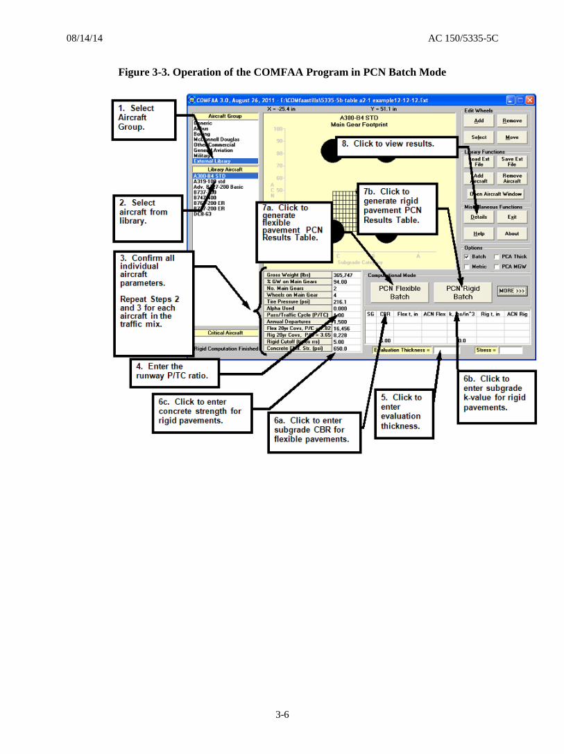
3.6.2.2 The program includes a help file to assist users. Figures 3-1, 3-2, and 3-3
summarize the operation of the COMFAA program.

08/14/14 AC 150/5335-5C
3-4
Figure 3-1. Computational Modes of the COMFAA Program

08/14/14 AC 150/5335-5C
3-5
Figure 3-2. Operation of the COMFAA Program in ACN Mode
08/14/14 AC 150/5335-5C
3-6
Figure 3-3. Operation of the COMFAA Program in PCN Batch Mode

08/14/14 AC 150/5335-5C
4-1
CHAPTER 4. DETERMINATION OF PCN NUMERICAL VALUE
4.1 PCN Concept.
The determination of a pavement rating in terms of PCN is a process of (1) determining
the ACN for each aircraft considered to be significant to the traffic mixture operating of
the subject pavement and (2) reporting the ACN value as the PCN for the pavement
structure. Under these conditions, any aircraft with an ACN equal to or less than the
reported PCN value can safely operate on the pavement subject to any limitations on
tire pressure.
Note: PCN values determined in accordance with this AC depend upon the aircraft
traffic used to determine the PCN value. Airports should re-evaluate their posted PCN
value if significant changes to the original aircraft traffic occur.
4.2 Determination of Numerical PCN Value.
Determination of the numerical PCN value for a particular pavement can be based upon
one of two procedures: the “Using” aircraft method or the “Technical” evaluation
method. ICAO procedures permit member states to determine how PCN values will be
determined based upon internally developed pavement evaluation procedures. Either
procedure may be used to determine a PCN, but the methodology used must be reported
as part of the posted rating.
4.3 Using Aircraft Method to Determine PCN.
The Using aircraft method is a simple procedure where ACN values for all aircraft
currently permitted to use the pavement facility are determined and the largest ACN
value is reported as the PCN. This method is easy to apply and does not require
detailed knowledge of the pavement structure. Figures 4-1 and 4-2 show an example of
the Using Aircraft Method. The subgrade support category IS NOT a critical input
when reporting PCN based on the Using Aircraft Method. The recommended subgrade
support category when information IS NOT available should be Category B.
4.3.1 Assumptions of the Using Aircraft Method.
An underlying assumption with the Using aircraft method is that the pavement structure
has the structural capacity to accommodate all aircraft in the traffic mixture, and that
each aircraft is capable of operating on the pavement structure without weight
restriction. From a technical point of view, the Using Aircraft method assumes that the
number of total operations is equal to 10,000 coverages of the using aircraft with the
highest ACN. The methodology used to determine ACN/PCN does not consider the
critical design aircraft used to determine airport dimensional requirements.
4.3.2 Inaccuracies of the Using Aircraft Method.
The accuracy of this method is greatly improved when aircraft traffic information is
available. Significant over-estimation of the pavement capacity can result if an
excessively damaging aircraft, which uses the pavement on a very infrequent basis, is
used to determine the PCN. Likewise, significant under-estimation of the pavement
capacity can lead to uneconomic use of the pavement by preventing acceptable traffic

08/14/14 AC 150/5335-5C
4-2
from operating. Although there are no minimum limits on frequency of operation
before an aircraft is considered part of the normal traffic, the reporting agency must use
a rational approach to avoid overstating or understating the pavement capacity. A
consistent method based on a design period minimum frequency is recommended and
presented in Appendix C. The frequency recommended is equal to 1,000 coverages of
the aircraft with the highest ACN for the Using method.
Note: Use of the Using aircraft method is discouraged on a long-term basis due to the
concerns listed above.
Figure 4-1. Operation of COMFAA ACN Only Program, Version in Batch Mode

08/14/14 AC 150/5335-5C
4-3
Figure 4-2. COMFAA Program, ACN Only Version in Batch Mode
4.4 Technical Evaluation Method to Determine PCN.
4.4.1 The strength of a pavement section is difficult to summarize in a precise manner and
will vary depending on the unique combination of aircraft loading conditions, frequency
of operation, and pavement support conditions. The technical evaluation method
attempts to address these and other site-specific variables to determine reasonable
pavement strength. In general terms, for a given pavement structure and given aircraft,
the allowable number of operations (traffic) will decrease as the intensity of pavement
loading increases (increase in aircraft weight). It is entirely possible that two pavement
structures with different cross-sections will report similar strength. However, the
permissible aircraft operations will be considerably different. This discrepancy must be
acknowledged by the airport operator and may require operational limitations
administered outside of the ACN-PCN system. All of the factors involved in
determining a pavement rating are important, and it is for this reason that pavement
ratings should not be viewed in absolute terms, but rather as estimations of a
representative value. A successful pavement evaluation is one that assigns a pavement
strength rating that considers the effects of all variables on the pavement.
4.4.2 The accuracy of a technical evaluation is better than that produced with the Using
aircraft procedure but requires a considerable increase in time and resources. Pavement
evaluation may require a combination of on-site inspections, load-bearing tests, and
engineering judgment. It is common to think of pavement strength rating in terms of
ultimate strength or immediate failure criteria. However, pavements are rarely removed
from service due to instantaneous structural failure. A decrease in the serviceability of
a pavement is commonly attributed to increases in surface roughness or localized
distress, such as rutting or cracking. Determination of the adequacy of a pavement
structure must not only consider the magnitude of pavement loads but the impact of the
accumulated effect of traffic volume over the intended life of the pavement. The

08/14/14 AC 150/5335-5C
4-4
subgrade support category is a necessary input when reporting PCN based on the
Technical Method.
Note: There is no recommended subgrade support category when information is not
available.
4.4.2.1 Determination of the PCN Value.
The PCN numerical value is determined from an allowable load rating.
While it is important not to confuse the PCN value with a pavement design
parameter, the PCN is developed in a similar fashion. An allowable load
rating is determined by applying the same principles as those used for
pavement design. The process for determining the allowable load rating
takes factors such as frequency of operations and permissible stress levels
into account. Allowable load ratings are often discussed in terms of
aircraft gear type and maximum gross aircraft weight, as these variables are
used in the pavement design procedure. Missing from the allowable load
rating, but just as important, is frequency of operation. In determining an
allowable load rating, the evaluation must address whether the allowable
load rating represents the pavement strength over a reasonable frequency of
operation. Once the allowable load rating is established, the determination
of the PCN value is a simple process of determining the ACN of the aircraft
representing the allowable load and reporting the value as the PCN.
4.4.2.2 Concept of Equivalent Traffic.
The ACN-PCN method is based on design procedures that evaluate one
aircraft against the pavement structure. Calculations necessary to
determine the PCN can only be performed for one aircraft at a time. The
ACN-PCN method does not directly address how to represent a traffic
mixture as a single aircraft. To address this limitation, the FAA uses the
equivalent annual departure concept to consolidate entire traffic mixtures
into equivalent annual departures of one representative aircraft. The
procedure for evaluating equivalent annual departures for a given aircraft
from a traffic mixture is based on the cumulative damage factor concept
discussed in Appendix A.
4.4.2.3 Counting Aircraft Operations.
When evaluating or designing a pavement section, it is important to account
for the number of times the pavement will be stressed. As discussed in
paragraph 2.2, an aircraft may have to pass over a given section of
pavement numerous times before the portion of pavement considered for
evaluation receives one full stress application. While statistical procedures
exist to determine the passes required for one full stress application, the
evaluation of a pavement section for PCN determination must also consider
how aircraft use the pavement in question. The FAA uses a conservative
approach for pavement design procedures by assuming that each aircraft
using the airport must land and take off once per cycle. Since the arrival
or landing weight of the aircraft is usually less than the departure weight,
the design procedure only counts one pass at the departure weight for
analysis. The one pass at departure weight is considered as one annual

08/14/14 AC 150/5335-5C
4-5
departure and the arrival event is ignored. Appendix A provides a detailed
discussion of traffic analysis.
4.5 Limitations of the PCN.
The PCN value should not be used for pavement design or as a substitute for evaluation.
Pavement design and evaluation are complex engineering problems that require detailed
analyses. They cannot be reduced to a single number. The PCN rating system uses a
continuous scale to compare pavement capacity where higher values represent
pavements with larger load capacity.
4.6 Reporting the PCN.
The PCN system uses a coded format to maximize the amount of information contained
in a minimum number of characters and to facilitate computerization. The PCN for a
pavement is reported as a five-part number where the following codes are ordered and
separated by forward slashes: Numerical PCN value / Pavement type / Subgrade
category / Allowable tire pressure / Method used to determine the PCN. An example of
a PCN code is 80/R/B/W/T, which is further explained in paragraph 4.6.6.
4.6.1 Numerical PCN Value.
The PCN numerical value indicates the load-carrying capacity of a pavement in terms
of a standard single wheel load at a tire pressure of 181 psi (1.25 MPa). The PCN value
should be reported in whole numbers, rounding off any fractional parts to the nearest
whole number. For pavements of diverse strengths, the controlling PCN numerical
value for the weakest segment of the pavement should normally be reported as the
strength of the pavement. Engineering judgment may be required in that if the weakest
segment is not in the most heavily used part of the runway, then another representative
segment may be more appropriate to determine PCN.
4.6.2 Pavement Type.
For the purpose of reporting PCN values, pavement types are considered to function as
either flexible or rigid structures. Table 4-1 lists the pavement codes for the purposes of
reporting PCN.
Table 4-1. Pavement Codes for Reporting PCN
Pavement Type Pavement Code
Flexible F
Rigid R
4.6.2.1 Flexible Pavement.
Flexible pavements support loads through bearing rather than flexural
action. They comprise several layers of selected materials designed to
gradually distribute loads from the surface to the layers beneath. The

08/14/14 AC 150/5335-5C
4-6
design ensures that load transmitted to each successive layer does not
exceed the layer’s load-bearing capacity.
4.6.2.2 Rigid Pavement.
Rigid pavements employ a single structural layer, which is very stiff or rigid
in nature, to support the pavement loads. The rigidity of the structural layer
and resulting beam action enable rigid pavement to distribute loads over a
large area of the subgrade. The load-carrying capacity of a rigid structure is
highly dependent upon the strength of the structural layer, which relies on
uniform support from the layers beneath.
4.6.2.3 Composite Pavement.
Various combinations of pavement types and stabilized layers can result in
complex pavements that could be classified as between rigid or flexible. A
pavement section may comprise multiple structural elements representative
of both rigid and flexible pavements. Composite pavements are most often
the result of pavement surface overlays applied at various stages in the life
of the pavement structure. If a pavement is of composite construction, the
pavement type should be reported as the type that most accurately reflects
the structural behavior of the pavement. The method used in computing
the PCN is the best guide in determining how to report the pavement type.
For example, if a pavement is composed of a rigid pavement with a
bituminous overlay, the usual manner of determining the load-carrying
capacity is to convert the pavement to an equivalent thickness of rigid
pavement. In this instance, the pavement type should be reported as a rigid
structure. A general guideline is that when the bituminous overlay reaches
75 to 100 percent of the rigid pavement thickness the pavement can be
considered as a flexible pavement. It is permissible to include a note stating
that the pavement is of composite construction but only the rating type, “R”
or “F”, is used in the assessment of the pavement load capacity.
4.6.3 Subgrade Strength Category.
As discussed in paragraph 2.1, there are four standard subgrade strengths identified for
calculating and reporting ACN or PCN values. Tables 2-1 and 2-2 list the values for
rigid and flexible pavements.
4.6.4 Allowable Tire Pressure.
Table 4-2 lists the allowable tire pressure categories identified by the ACN-PCN
system. The tire pressure codes apply equally to rigid or flexible pavement sections;
however, the application of the allowable tire pressure differs substantially for rigid and
flexible pavements.

08/14/14 AC 150/5335-5C
4-7
Table 4-2. Tire Pressure Codes for Reporting PCN
Category Code Tire Pressure Range
Unlimited W No pressure limit
High X Pressure limited to 254 psi (1.75 MPa)
Medium Y Pressure limited to 181 psi (1.25 MPa)
Low Z Pressure limited to 73 psi (0.50 MPa)
4.6.4.1 Tire Pressures on Rigid Pavements.
Aircraft tire pressure will have little effect on pavements with Portland
cement concrete (concrete) surfaces. Rigid pavements are inherently strong
enough to resist tire pressures higher than currently used by commercial
aircraft and can usually be rated as code W.
4.6.4.2 Tire Pressures on Flexible Pavements.
Tire pressures may be restricted on asphaltic concrete (asphalt), depending
on the quality of the asphalt mixture and climatic conditions. Tire pressure
effects on an asphalt layer relate to the stability of the mix in resisting
shearing or densification. A poorly constructed asphalt pavement can be
subject to rutting due to consolidation under load. The principal concern in
resisting tire pressure effects is with stability or shear resistance of lower
quality mixtures. A properly prepared and placed mixture that conforms to
FAA specification Item P-401 can withstand substantial tire pressure in
excess of 218 psi (1.5 Mpa). Item P-401, Hot Mix Asphalt (HMA)
Pavements, is provided in the current version of AC 150/5370-10,
Standards for Specifying Construction of Airports. Improperly prepared
and placed mixtures can show distress under tire pressures of 100 psi (0.7
MPa) or less. Although these effects are independent of the asphalt layer
thickness, pavements with well-placed asphalt of 4 to 5 inches (10.2 to 12.7
cm) in thickness can generally be rated with code X or W, while thinner
pavement of poorer quality asphalt should not be rated above code Y.
4.6.5 Method Used to Determine PCN.
The PCN system recognizes two pavement evaluation methods. If the evaluation
represents the results of a technical study, the evaluation method should be coded T. If
the evaluation is based on “Using aircraft” experience, the evaluation method should be
coded U. Technical evaluation implies that some form of technical study and
computation were involved in the determination of the PCN. Using aircraft evaluation
means the PCN was determined by selecting the highest ACN among the aircraft
currently using the facility and not causing pavement distress. PCN values computed
by the technical evaluation method should be reported to the NASR database and shown
on the FAA Form 5010, Airport Master Record. Publication of a Using aircraft
evaluation in the Airport Master Record, Form 5010, and the NASR database is
permitted only by mutual agreement between the airport owner and the FAA.

08/14/14 AC 150/5335-5C
4-8
4.6.6 Example PCN Reporting.
An example of a PCN code is 80/R/B/W/T—with 80 expressing the PCN numerical
value, R for rigid pavement, B for medium strength subgrade, W for high allowable tire
pressure, and T for a PCN value obtained by a technical evaluation.
4.6.7 Report PCN Values to FAA (See Appendix E).
Once a PCN value and the coded entries are determined, the PCN code should be
reported to the appropriate regional FAA Airports Division, either in writing or as part
of the annual update to the Airport Master Record, FAA Form 5010-l. The PCN code
will be disseminated by the National Flight Data Center through aeronautical
publications such as the Airport/Facility Directory (AFD) and the Aeronautical
Information Publication (AIP). An aircraft’s ACN can then be compared with published
PCN’s to determine if pavement strength places any restrictions on the aircraft
operating on that pavement, such as the aircraft’s tire pressure or load.

08/14/14 AC 150/5335-5C
Appendix A
A-1
APPENDIX A. EQUIVALENT TRAFFIC
Equivalent Traffic. A.1
A.1.1 A detailed method based on the cumulative damage factor (CDF) procedure allows the
calculation of the combined effect of multiple aircraft in the traffic mix for an airport.
This combined traffic is brought together into the equivalent traffic of a critical aircraft.
This is necessary since the procedure used to calculate ACN allows only one aircraft at
a time. By combining all of the aircraft in the traffic mix into an equivalent critical
aircraft, calculation of a PCN that includes the effects of all traffic becomes possible.
The methodology used to determine ACN/PCN does not consider the critical design
aircraft used to determine airport dimensional requirements.
A.1.2 The assessment of equivalent traffic, as described in this section, is needed only in the
process of determining PCN using the technical method and may be disregarded when
the Using aircraft method is employed.
A.1.3 In order to arrive at a technically derived PCN, it is necessary to determine the
maximum allowable gross weight of each aircraft in the traffic mixture, which will
generate the known pavement structure. This in turn requires that the pavement cross-
section and aircraft loading characteristics be examined in detail. Consequently, the
information presented in this appendix appears at first to apply to pavement design
rather than a PCN determination. However, with this knowledge in hand, an engineer
will be able to arrive at a PCN that will have a solid technical foundation.
Equivalent Traffic Terminology. A.2
In order to determine a PCN, based on the technical evaluation method, it is necessary
to define common terms used in aircraft traffic and pavement loading. The terms
arrival, departure, pass, coverage, load repetition, operation, and traffic cycle are often
used interchangeably by different organizations when determining the effect of aircraft
traffic operating on a pavement. It is important to determine which aircraft movements
need be counted when considering pavement stress and how the various movement
terms apply in relation to the pavement design and evaluation process. For the purposes
of this document, they are differentiated as follows:
A.2.1 Arrival (Landing) and Departure (Takeoff).
Typically, aircraft arrive at an airport with a lower amount of fuel than is used at
takeoff. As a consequence, the stress loading of the wheels on the runway pavement is
less when landing than at takeoff due to the lower weight of the aircraft as a result from
the fuel used during flight and the lift on the wings. This is true even at the touchdown
impact in that there is still lift on the wings, which alleviates the dynamic vertical force.
Because of this, the FAA pavement design procedure only considers departures and
ignores the arrival traffic count. However, if the aircraft do not receive additional fuel
at the airport, then the landing weight will be substantially the same as the takeoff
weight (discounting the changes in passenger count and cargo), and the landing
operation should be counted as a takeoff for pavement stress loading cycles. In this
latter scenario, there are two equal load stresses on the pavement for each traffic count

08/14/14 AC 150/5335-5C
Appendix A
A-2
(departure), rather than just one. Regardless of the method of counting load stresses, a
traffic cycle is defined as one takeoff and one landing of the same aircraft, subject to a
further refinement of the definition in the following text.
A.2.2 Pass.
A pass is a one-time movement of the aircraft over the runway pavement. It could be an
arrival, a departure, a taxi operation, or all three, depending on the loading magnitude
and the location of the taxiways. Figure A-1 shows typical traffic patterns for runways
having either parallel taxiways or central taxiways. A parallel taxiway requires that
none or very little of the runway be used as part of the taxi movement. A central
taxiway requires that a large portion of the runway be used during the taxi movement.
Figure A-1. Traffic Load Distribution Patterns
Parallel Taxiway Scenario. A.2.2.1
In the case of the parallel taxiway, shown as Figure A1-1a in Figure A-1,
two possible loading situations can occur. Both of these situations assume
that the passenger count and cargo payload are approximately the same for
the entire landing and takeoff cycle:
1. If the aircraft obtains fuel at the airport, then a traffic cycle consists of
only one pass since the landing stress loading is considered at a reduced
level, which is a fractional equivalence. For this condition only the
takeoff pass is counted, and the ratio of passes to traffic cycles (P/TC)
is 1.
2. If the aircraft does not obtain fuel at the airport, then both landing and
takeoff passes should be counted, and a traffic cycle consists of two
passes of equal load stress. In this case, the P/TC ratio is 2.

08/14/14 AC 150/5335-5C
Appendix A
A-3
Central Taxiway Scenario. A.2.2.2
For a central taxiway configuration, shown as Figure A1-1b in Figure A-1,
there are also two possible loading situations that can occur. As was done
for the parallel taxiway condition, both of these situations assume that the
payload is approximately the same for the entire landing and takeoff cycle:
1. If the aircraft obtains fuel at the airport, then both the takeoff and taxi to
takeoff passes should be counted since they result in a traffic cycle
consisting of two passes at the maximum load stress. The landing pass
can be ignored in this case. It is recognized that only part of the runway
is used during some of these operations, but it is conservative to assume
that the entire runway is covered each time a pass occurs. For this
situation, the P/TC ratio is 2.
2. If the aircraft does not obtain fuel at the airport, then both the landing
and takeoff passes should be counted, along with the taxi pass, and a
traffic cycle consists of three passes at loads of equal magnitude. In
this case, the P/TC ratio is 3.
A simplified, but less conservative, approach would be use a P/TC ratio of 1 A.2.2.3
for all situations. Since a landing and a takeoff only apply full load to
perhaps the end third of the runway (opposite ends for no shift in wind
direction), this less conservative approach could be used to count one pass
for both landing and takeoff. However, the FAA recommends conducting
airport evaluations on the conservative side, which is to assume any one of
the passes covers the entire runway.
Table A-1 summarizes the standard P/TC ratio discussion. A.2.2.4
Table A-1. Standard P/TC Ratio Summary (see Note)
Taxiway
Serving the
Runway
P/TC
Fuel Obtained at the Airport
(i.e. departure gross weight more
than arrival gross weight.)
P/TC
No Fuel Obtained at the Airport
(i.e. departure gross weight same
as arrival gross weight.)
Parallel 1 2
Central 2 3
Note: The standard P/TC ratios are whole numbers 1, 2, and 3. The range of values that
can be entered in the software is 0.001 thru 10.0. This feature allows flexibility in those
instances where a fraction of the total traffic may use different runways or other
pavements. For example, a P/TC ratio of 0.5 multiplies the coverages of each aircraft by
0.5, which will increase the PCN of the pavement.

08/14/14 AC 150/5335-5C
Appendix A
A-4
A.2.3 Coverage.
When an aircraft moves along a runway, it seldom travels in a perfectly A.2.3.1
straight line or over the exact same wheel path as before. It will wander on
the runway with a statistically normal distribution. One coverage occurs
when a unit area of the runway has been traversed by a wheel of the aircraft
main gear. Due to wander, this unit area may not be covered by the wheel
every time the aircraft is on the runway. The number of passes required to
statistically cover the unit area one time on the pavement is expressed by
the pass to coverage (P/C) ratio.
Although the terms coverage and P/C ratio have commonly been applied to A.2.3.2
both flexible and rigid pavements, the P/C ratio has a slightly different
meaning when applied to flexible pavements as opposed to rigid pavements.
This is due to the manner in which flexible and rigid pavements are
considered to react to various types of gear configurations. For gear
configurations with wheels in tandem, such as dual tandem (2D) and triple
dual tandem (3D), the ratios are different for flexible and rigid pavements,
and using the same term for both types of pavements may become
confusing. It is incumbent upon the user to select the proper value for
flexible and rigid pavements.
Aircraft passes can be determined (counted) by observation but coverages A.2.3.3
are used by the COMFAA program. The P/C ratio is necessary to convert
passes to coverages for use in the program. This ratio is different for each
aircraft because of the different number of wheels, main gear
configurations, tire contact areas, and load on the gear. Fortunately, the P/C
ratio for any aircraft is automatically determined by the COMFAA program
and the user only need be concerned with passes.
A.2.4 Operation.
The meaning of this term is unclear when used in pavement design or evaluation. It
could mean a departure at full load or a landing at minimal load. It is often used
interchangeably with pass or traffic cycle. When this description of an aircraft activity
is used, additional information should be supplied. It is usually preferable to use the
more precise terms described in this section.
A.2.5 Annual Departure and Traffic Cycle Ratio.
The FAA standard for counting traffic cycles at an airport for pavement A.2.5.1
design purposes is to count one landing, one taxi, and one take-off as a
single event called a departure. For pavement evaluation related to
determination of PCN, it may be necessary to adjust the number of traffic
cycles (departures) based upon the scenarios discussed in paragraph 1.1b of
this appendix. Similar to the discussion above regarding P/C ratio, the
traffic cycle to coverage (TC/C) ratio is needed to finalize the equivalent
traffic determination. The TC/C ratio differs when applied to flexible
pavements as opposed to rigid pavements. The ratio in flexible pavement,
rather than passes to coverages, is required since there could be one or more

08/14/14 AC 150/5335-5C
Appendix A
A-5
passes per traffic cycle. When only one pass on the operating surface is
assumed for each traffic count, then the P/C ratio is sufficient. However,
when situations are encountered where more than one pass is considered to
occur during the landing to takeoff cycle, then the TC/C ratio is necessary
in order to properly account for the effects of all of the traffic. These
situations occur most often when there are central taxiways or fuel is not
obtained at the airport.
Equation A-1 translates the P/C ratio to the TC/C ratio for flexible and rigid A.2.5.2
pavements by including the previously described ratio of passes to traffic
cycles (P/TC):
TCPCPCTC (Equation A-1)
Where:
TC = Traffic Cycles
C = Coverages
P = Passes
Since the COMFAA program will automatically determine passes to A.2.5.3
coverages and convert annual departures to coverages, the conditions
described in paragraph A.2.2 can be addressed by simply multiplying
annual departures by the pass to traffic cycle (P/TC) ratio. COMFAA
requires the P/TC ratio parameter and will automatically perform this
multiplication.
Equivalent Traffic Calculations. A.3
A.3.1 In order to complete the equivalent traffic calculations for converting one of the aircraft
in the mix to another, a procedure based on cumulative damage factor (CDF) is used.
The CDF method is similar to the one used in the design procedures embodied in the
design program FAARFIELD, required by AC 150/5320-6, and provides more
consistent results than the wheel load method (as in FAA’s CBR and Westergaard
methods) when the traffic mix contains a wide range of gear geometries and strut loads.
The primary difference between the CDF procedure used here and the one in
FAARFIELD is that in FAARFIELD, the CDF is summed over all aircraft to produce
the criterion for design whereas in the procedure used here the CDF methodology is
used to convert the traffic for the complete mix into an equivalent number of coverages
of one of the aircraft in the mix. That aircraft is designated the “critical” aircraft or
“most demanding” aircraft for PCN determination or the “design” aircraft for thickness
design (FAA’s CBR and Westergaard methods). The wheel load method is briefly
described before describing the CDF method.

08/14/14 AC 150/5335-5C
Appendix A
A-6
A.3.2 In the wheel load method, select one of the aircraft in the mix to be the critical aircraft
and then convert the traffic of the remaining aircraft into equivalent traffic of the critical
aircraft. First, with equation A-1, convert the traffic for the gear type of each of the
conversion aircraft into equivalent traffic for the same gear type as the critical aircraft.
)(8.0 NM
CNVCRTGE TCTC (Equation A-2)
Where:
TCCNV = the number of traffic cycles of the conversion aircraft.
TCCRTGE = the number of traffic cycles of the critical aircraft
equivalent to the number of traffic cycles of the
conversion aircraft due to gear type equivalency.
N = the number of wheels on the main gear of the
conversion aircraft.
M = the number of wheels on the main gear of the critical
aircraft.
A.3.3 Second, with equation A-3, convert the gear equivalency traffic cycles into equivalent
traffic based on load magnitude.
CNVCRT WW
CRTGECRTE
CNV
CRTCRTGECRTE
TCTC
W
WTCTC
Or
LogLog
(Equation A-3)
Where:
TCCRTE = the number of traffic cycles of the critical aircraft
equivalent to the number of traffic cycles of the
conversion aircraft due to gear type and load magnitude
equivalencies.
WCNV = the wheel load of the conversion aircraft.
WCRT = the wheel load of the critical aircraft.
A.3.4 Alternatively, both operations can be combined into a single equation:
CNVCRT WWNM
CNVCRTE TCTC )(8.0 (Equation A-4)

08/14/14 AC 150/5335-5C
Appendix A
A-7
A.3.5 Finally, the equivalent traffic cycles of all of the conversion aircraft are added to the
original traffic cycles of the critical aircraft to give the total equivalent traffic cycles of
the critical aircraft.
A.3.6 In the CDF method, the number of equivalent traffic cycles of the critical aircraft is
defined as the number of traffic cycles of the critical aircraft that will cause the same
amount of damage to the pavement as the number of traffic cycles of the conversion
aircraft, where damage is defined by CDF.
A.3.7 CDF is derived from Miner’s Rule, which states the damage induced in a structural
element is proportional to the number of load applications divided by the number of
load applications required to fail the structural element. In airport pavement design, load
applications are counted in coverages, so the relationship for calculating equivalent
traffic is first derived in terms of coverages.
aircraft conversion theof coverages thefrom resultingfactor damage cumulative
aircraft conversion by the loadedhen pavement w thefail tocoverages
aircraft conversion theof coverages
CNVF
CNVCNV
C
CCDF
aircraft critical theof coverages equivalent thefrom resultingfactor damage cumulative
aircraft critical by the loadedhen pavement w thefail tocoverages
aircraft critical theof coverages equivalent
CRTF
CRTECRTE
C
CCDF
A.3.8 CDF is the fraction of the total pavement life used up by operating the indicated aircraft
on the pavement. It therefore follows that the CDF for the equivalent critical aircraft is
equal to the CDF for the conversion aircraft. Or:
and ,CNVF
CNV
CRTF
CRTE
C
C
C
C
CNV
CNVF
CRTFCRTE C
C
CC
(Equation A-5)
But: CRTECRTCRTE
CNVCNVCNV
CPCTCCPCTC and ,
Where:
TCCNV = the number of traffic cycles of the conversion aircraft.
TCCRTE = the number of traffic cycles of the critical aircraft equivalent
to the number of traffic cycles of the conversion aircraft.
PCCNV = pass-to-coverage ratio for the conversion aircraft.
PCCRT = pass-to-coverage ratio for the critical aircraft.

08/14/14 AC 150/5335-5C
Appendix A
A-8
A.3.9 Therefore, the equivalent traffic cycles of the critical aircraft by the CDF method is
given by:
CNV
CNVF
CRTF
CNV
CRTCRTE TC
C
C
PC
PCTC
(Equation A-6)
A.3.10 Equation A-6 can be rewritten as:
CNVICRTFCRTEI CDFCC
Where:
CCRTEI = the number of equivalent coverages of the Ith aircraft in the
list, including the critical aircraft.
CDFCNVI = the CDF of the Ith aircraft in the list, including the critical
aircraft.
A.3.11 Summing over all aircraft in the list gives the total number of equivalent coverages of
the critical aircraft, CCRTETotal, as:
N
I
CNVICRTF
N
I
CNVICRTF
N
I
CRTEICRTETotal CDFCCDFCCC111
Where N = the total number of aircraft in the list, including the critical
aircraft.
A.3.12 Defining the total CDF for the traffic mix, CDFT, as the total number of equivalent
coverages of the critical aircraft divided by the number of coverages to failure of the
critical aircraft, gives the equation:
N
I
CNVI
CRTF
CRTETotalT CDF
C
CCDF
1 (Equation A-7)
A.3.13 The total CDF for the traffic mix is therefore, by this definition, the sum of the CDFs of
all of the aircraft in the traffic mix, including that of the critical aircraft.
A.3.14 Table A-2 shows how the above calculations are combined, using the COMFAA Life
calculation with the Batch option checked, to determine the equivalent traffic cycles of
the critical aircraft. The pavement is assumed to be a flexible structure 33.80 inches
thick on a CBR 8 subgrade. For this example, assume that the B747-400 is the critical
aircraft. Also assume that the P/TC ratio is 1.0 so Traffic Cycles equals Annual
Departures. Referring to the Top table, the CDF contribution of each aircraft on the
pavement is calculated by dividing 20-year Coverages (Column 7) by Life (Column 9),
with results shown in the Bottom portion of the table. The B747-400 is the assumed
critical aircraft, so the operations of all other aircraft are equated to the B747-400. The
results are shown in Column 11 of the Bottom portion of the table. Column 11 results
use equation A-6, i.e., (3000/0.6543)*Col. 10. The sum of the equivalent annual
departures (Equation A-7) indicates that all other aircraft are equivalent to 468
departures of the B747-400.

08/14/14 AC 150/5335-5C
Appendix A
A-9
Table A- 3. Example of COMFAA Batch Life Calculations
A.3.15 The Top portion of the table can be viewed in the Details window in the program after
executing the Life function for Flexible pavement with all computation features
available (shown when the “MORE” button is clicked). Pavement thickness and
subgrade strength must be entered in the program for the Life function to work
correctly. Results for all aircraft in the list will be computed and displayed if the Batch
box is checked. Otherwise, results for only one aircraft are displayed. Detailed
instructions are given later for operating the program.
A.3.16 Coverages to failure for each individual aircraft is computed in the program by
changing the number of coverages for that aircraft until the design thickness by the
CBR method (for flexible pavements) is the same as the evaluation pavement thickness,
in this case 33.8 inches. As explained above, CDF is the ratio of applied coverages to
coverages to failure, and is a measure of the amount of damage done to the pavement by
that aircraft over a period of 20 years (under the assumptions implicit in the design
procedure). If the CDF for any aircraft is equal to one, then the pavement is predicted to
fail in 20 years if it is the only aircraft in operation. If the sum of the CDFs for all
aircraft in the list is equal to one, then the pavement is predicted to fail in 20 years with
all of the aircraft operating at their assumed operating weights and annual departures.
Example using
B747-400 as the
critical aircraft
Col 11 converts
all to B747-400
departures
Col 11 = 3,000
multiplied by
(Col 10) / 0.6543
Table A-2. Example of COMFAA Batch Life Calculations

08/14/14 AC 150/5335-5C
Appendix A
A-10
The sum of the CDFs in this example is 0.7564, indicating that the pavement is being
operated under a set of conservative assumptions.
A.3.17 It should be noted that the sum of the CDFs as calculated in COMFAA do not strictly
provide a prediction of pavement damage caused by the accumulation of damage from
all of the aircraft because not all of the aircraft landing gears pass down the same
longitudinal path. The summation given here would therefore provide a somewhat
conservative result than expected. In comparison with the FAARFIELD computer
program, the COMFAA values correspond to the “CDF Max for Aircraft” values from
FAARFIELD. The “CDF Contribution” values from FAARFIELD are summed along
defined longitudinal paths and do not correspond to the values from COMFAA, except
when the Contribution and Max for Aircraft values coincide. This discussion indicates
how, all other things being equal, the equivalent critical aircraft concept used in FAA’s
CBR and Westergaard methods and in COMFAA, produces more conservative designs
than the procedure used in FAARFIELD, and why the two methodologies can never be
made to produce the same predictions of pavement life for different traffic mixes. For a
new design using FAARFIELD in which the design thickness is determined based on
CDF=1.0 for the traffic mix, the PCN determined from COMFAA will not reflect the
true pavement design life. In this situation, consider setting the PCN = ACN of the
highest using aircraft.

08/14/14 AC 150/5335-5C
Appendix B
B-1
APPENDIX B. TECHNICAL EVALUATION METHOD—EVALUATION PAVEMENT PROPERTIES DETERMINATION
Technical Evaluation Method. B.1
The Technical Evaluation method for determining a PCN requires pavement thickness
and cross-sectional properties as well as traffic mix details.
Flexible Pavement Cross-Section Properties—Equivalent Thickness B.2
Determination.
B.2.1 For evaluation purposes, the actual thickness of the flexible pavement section under
consideration must be converted to a standard flexible pavement section.. The standard
section, which corresponds to the total thickness requirement calculated by the
COMFAA program, assumes a defined layer thickness for the asphalt surface, a
defined layer thickness of aggregate base material with a CBR 80 or higher, and a
variable thickness subbase layer with a CBR 20 or greater. For flexible pavement
systems, two standard structural reference sections have been defined.
B.2.2 When no aircraft in the traffic mix have four or more wheels on a main gear, the
reference structure to be used is: 3 inches asphalt surface course (P401) and 6 inches
crushed aggregate base course (P209). When one or more aircraft in the traffic mix have
four or more wheels on a main gear, the reference structure to be used is: 5 inches
asphalt surface course (P401) and 8 inches crushed aggregate base course (P209).
Table 3. Reference Structure for Traffic Mix with 4 or More Wheels
Reference Structural
Layer Thickness
(inches)
Less than Four
Wheels on Main
Gear
Four or More
Wheels on Main
Gear
Asphaltic Concrete
(FAA Item P-401) 3 5
High Quality Granular
Base (FAA Item P-209) 6 8

08/14/14 AC 150/5335-5C
Appendix B
B-2
B.2.3 If the pavement has excess material or improved materials, the total pavement thickness
may be increased according to the FAA CBR method summarized herein as Figures B-1
and B-2 and Table B-1. The pavement is considered to have excess asphalt, which can
be converted to extra equivalent thickness, when the asphalt thickness is greater than the
minimum thickness of asphalt surfacing of the referenced pavement section. The
pavement may also be considered to have excess aggregate base thickness when the
cross-section has a high quality crushed aggregate base thickness greater than the
minimum thickness of high quality crushed aggregate base of the referenced pavement
section or when other improved materials, such as asphalt stabilization or cement
treated materials, are present. Likewise, additional improved base materials may also
be converted to additional subbase material to add to the total pavement thickness.
B.2.4 If the evaluation pavement section is deficient for asphalt pavement surface course (i.e.
less than 3 inches) and/or high quality crushed aggregate base course (i.e. less than 6
inches), the subbase thickness is reduced using a slightly more conservative inverse
layer equivalency factor for surface course material and/or the subbase thickness is
reduced using a slightly more conservative inverse layer equivalency factor for high
quality crushed aggregate base material. This is shown in Table B-1.
Table B-1. FAA Flexible Pavement Layer Equivalency Factor Range
Note: Engineering judgment may be used to adjust recommended factors for all
Structural Items within the ranges shown in the table. Include justification for higher or
lower conversion factors than recommended factors when reporting PCN values.
Rigid Pavement Cross-Section Properties—Improved Subgrade Support B.3
Determination.
The rigid pavement characteristics—including subgrade soil modulus, k, the concrete
thickness, and flexural strength—are needed for PCN determination. The foundation
modulus (k value) is assigned to the material directly beneath the concrete pavement

08/14/14 AC 150/5335-5C
Appendix B
B-3
layer. However, the k value for the subgrade is determined and then adjusted to account
for improved layers (subbases) between the subgrade and the concrete layer. There are
k value corrections available for uncrushed aggregate subbases, crushed aggregate
subbases, and subbases stabilized with asphalt cement or Portland cement. The k value
may be increased according to the methods described in the FAA Westergaard method,
summarized herein as Figures B-3 through B-6. The thickness of the concrete in a rigid
pavement may be increased if an asphalt overlay has been placed on the surface. The
thickness may be increased using the factor described in the FAA Westergaard method,
summarized herein as Figure B-7. Each 2.5 inches of asphalt may be converted to 1.0
inch of concrete. The references for both improvement subgrade support guidance and
additional thickness conversion guidance is summarized in Table B-2.
Table B-2. FAA Rigid Pavement Subbase Effect on Foundation k Value
FAA Pavement Layer
Effect When
Uncrushed
Aggregate (Bank
Run Sand and
Gravel) is Used as
the Subbase
Effect When Well-
Graded Crushed
Aggregate is Used
as the Subbase
Effect When Asphalt
Cement or Portland
Cement Stabilized
Materials are Used as
the Subbase
P-401 and/or P-403 Ref. Figure B-6
P-306 Ref. Figure B-6
P-304 Ref. Figure B-6
P-209 Ref. Figure B-5,
Upper Graph
P-208 and/or P-211 Ref. Figure B-5,
Lower Graph
P-301 Ref. Figure B-5,
Lower Graph
P-154 Ref. Figure B-5,
Lower Graph
Effect on Rigid Pavement Thickness
P-401 Overlay Ref. Figure B-7
Availability of Support Program to Determine Pavement Characteristics. B.4
To facilitate the use of the ACN-PCN system, FAA developed a software application
that incorporates the guidance in this appendix and determines the evaluation thickness

08/14/14 AC 150/5335-5C
Appendix B
B-4
for both flexible and rigid pavements and the foundation k value for rigid pavements.
The software may be downloaded from the FAA website.3
Using the Support Program. B.5
The support program is a spreadsheet, which may be updated periodically. Examples
are shown in Figure C-2 and Figure C-3.
3 See http://www.faa.gov/airports/engineering/design_software/. This software is in the public domain.

08/14/14 AC 150/5335-5C
Appendix B
B-5
Figure B-1. Flexible Pavement Stabilized Base Layer(s) Equivalency Discussion
(FAA CBR method)

08/14/14 AC 150/5335-5C
Appendix B
B-6
Figure B-2. Flexible Pavement Stabilized Base Layer(s) Equivalency Discussion
(Continued) (FAA CBR method)

08/14/14 AC 150/5335-5C
Appendix B
B-7
Figure B-3. Rigid Pavement Stabilized Subbase Layer(s) Discussion
(FAA Westergaard method)

08/14/14 AC 150/5335-5C
Appendix B
B-8
Figure B-4. Rigid Pavement Stabilized Subbase Layer(s) Discussion (Continued)
(FAA Westergaard method)

08/14/14 AC 150/5335-5C
Appendix B
B-9
Figure B-5. Subbase Layer Effect on Subgrade Support, k, for Rigid Pavement
(FAA Westergaard method)

08/14/14 AC 150/5335-5C
Appendix B
B-10
Figure B-6. Stabilized Subbase Layer Effect on Subgrade Support, k, for Rigid Pavement
(FAA Westergaard method)

08/14/14 AC 150/5335-5C
Appendix B
B-11
Figure B-7. Flexible Pavement quivalency to Rigid Pavement
(FAA Westergaard method)

08/14/14 AC 150/5335-5C
Appendix B
B-12
Page Intentionally Blank

08/14/14 AC 150/5335-5C
Appendix C
C-1
APPENDIX C. PCN DETERMINATION EXAMPLES
The Using Aircraft Method. C.1
C.1.1 The Using aircraft method of determining PCN is presented in the following steps. This
procedure can be used when there is limited knowledge of the existing traffic and
runway characteristics. It is also useful when engineering analysis is neither possible
nor desired. Airport authorities should be more careful in the application of a Using
aircraft PCN in that the rating has not been rigorously determined.
C.1.2 There are basic steps required to arrive at a Using aircraft PCN:
Determine the ACN for each aircraft in the traffic mix currently using the pavement.
Assign the highest ACN value as the PCN.
C.1.3 These steps are explained below in greater detail. Figure C-1 shows the steps needed to
automatically perform the ACN calculations using COMFAA along with the results.

08/14/14 AC 150/5335-5C
Appendix C
C-2
Figure C-1. Example of COMFAA ACN Batch Results
1. Load Ext file.
2. Click More to access ACN Computational
Mode.
3. Check Batch.
4. Click Flexible Button or Rigid Button.
5. When calculations finish, click Details
Button.
6. View results.
7. Select highest ACN for the pavement’s
subgrade category.
1. Assign the pavement surface type as code F or R.
2. From available records, determine the strength of the pavement subgrade. If the
subgrade strength is not known, make a judgment of Medium or Low
3. Determine which aircraft has the highest ACN from the list of aircraft that regularly
use the pavement, based on the surface type code assigned in Step 1 and the
subgrade code in Step 2. ACN values may be determined from the COMFAA
program or from ACN graphs found in the manufacturer’s published ACAP
manuals. Use the same subgrade code for each of the aircraft when determining the
maximum ACN. Base ACNs on the highest operating weight of the aircraft at the
airport if the data is available; otherwise, use an estimate or the published maximum
allowable gross weight of the aircraft in question. Report the ACN from the aircraft
with the highest ACN that regularly uses the pavement as the PCN for the
pavement. NOTE: The FAA recommends that an aircraft be considered to
'regularly use' the pavement if the 20-year total of coverages exceeds 1,000. The
number of annual departures of the aircraft corresponding to this coverage level can
be obtained from COMFAA by switching to PCN or Thickness mode and entering
1000 in the 'Flex 20yr Coverages' or 'Rigid 20yr Coverages' field, as appropriate. In

08/14/14 AC 150/5335-5C
Appendix C
C-3
COMFAA, coverages are independent of subgrade strength, so an arbitrary CBR or
k value can be entered in the appropriate field to compute coverages.
4. The PCN is simply the highest ACN with appropriate tire pressure and evaluation
codes added. The numerical value of the PCN may be adjusted up or down at the
preference of the airport authority. Adjustments are not considered standard
practice but reasons for adjustment may include local restrictions, allowances for
certain aircraft, or pavement conditions.
5. The tire pressure code (W, X, Y, or Z) should represent the highest tire pressure of
the aircraft fleet currently using the pavement. For flexible pavements, code X
should be used if no higher tire pressure is evident from among the existing traffic.
It is commonly understood that concrete can tolerate substantially higher tire
pressures, so the rigid pavement rating should normally be given as W.
6. The evaluation method for the Using aircraft method is reported as U.
Using Aircraft Example for Flexible Pavements. C.2
C.2.1 The following example illustrates the Using aircraft PCN process for flexible
pavements:
C.2.2 An airport has a runway with the known traffic mix shown in Table C-1. The runway
has a flexible (asphalt-surfaced) pavement with an estimated subgrade strength of CBR
9, which puts it in subgrade category B. The flexible pavement ACNs for each aircraft
in the mix are shown in Table C-1.

08/14/14 AC 150/5335-5C
Appendix C
C-4
Table C-1. Using Aircraft and Traffic for a Flexible Pavement
Since this is a flexible pavement, the pavement type code is F, (Table 4-1).
The subgrade strength under the pavement is CBR 9, or Medium category, so the
appropriate code is B (Table 2-2).
The highest tire pressure of any aircraft in the traffic mix is 216.1 psi, so the tire
pressure code is X (Table 4-2).
From the above list, the critical aircraft is the B747-400, because it has the highest
ACN of the group at the operational weights shown (59.3/F/B). Additionally, it has
regular service.
Since there was minimal engineering analysis done in this example, and the rating
was determined simply by examination of the current aircraft using the runway, the
evaluation code from Paragraph 4.6.5 is U.
Based on the results of the previous steps, the runway pavement should tentatively
be rated as PCN 59/F/B/X/U, assuming that the pavement is performing
satisfactorily under the current traffic.
If this pavement was a taxiway, the airport could rate this taxiway as the same PCN.

08/14/14 AC 150/5335-5C
Appendix C
C-5
C.2.3 If the pavement shows obvious signs of distress, this rating should be adjusted
downward by the airport authority. If the rating is lowered, then one or more of the
aircraft will have ACNs that exceed the assigned rating. This may require the airport to
restrict the allowable gross weight for those aircraft or consider pavement
strengthening.
Using Aircraft Example for Rigid Pavements. C.3
An airport has a runway with the known traffic mix shown in Table C-2. The runway
has a rigid (concrete-surfaced) pavement with an estimated k-value of 300 lbs/in3,
which puts it in subgrade category B. The rigid pavement ACNs for each aircraft in the
mix are shown in Table C-2.
Table C-2. Using Aircraft and Traffic for a Rigid Pavement
Since this is a rigid pavement, the pavement type code is R (Table 4-1).
The subgrade strength under the pavement is k=300 pci, which is Medium category,
so the appropriate code is B (Table 2-1).
Concrete surfaces can tolerate high tire pressures, so tire pressure code W found in
Table 4-2 should be used for rigid pavement.
The B777-200 has the highest ACN of the group at the operational weights shown
(63.6/R/B/W).

08/14/14 AC 150/5335-5C
Appendix C
C-6
Since there was no engineering analysis done in this example, and the rating was
determined simply by examination of the current aircraft using the runway, the
evaluation code from Paragraph 4.6.5 is U.
Based on these steps, the pavement should tentatively be rated as PCN 64/R/B/W/U
in order to accommodate all of the current traffic.
If the pavement shows obvious signs of distress, this rating should be adjusted
downward by the airport authority. If the rating is lowered, then one or more of the
aircraft will have ACNs that exceed the assigned rating. This may require the
airport to restrict the allowable gross weight for those aircraft or consideration of
pavement strengthening. The rating could also be adjusted upward, depending on
the performance of the pavement under the current traffic.
The Technical Evaluation Method. C.4
Use the technical evaluation method of determining PCN when there is reliable
knowledge of the existing traffic and pavement characteristics. Total thickness and
cross-sectional data are needed to determine the equivalent pavement thickness as
described in detail in section 2.1. Although the technical evaluation provides a good
representation of existing conditions, the airport authority should recognize there are
many variables in the pavement structure as well as the method of analysis itself. The
objective of the technical method is to consolidate all traffic into equivalent annual
departures, determine allowable gross weight, and assess the ACN for each aircraft in
the traffic mixture so that a realistic PCN is selected.
Figure C-2. Flexible Layer Equivalency Spreadsheet to Support COMFAA

08/14/14 AC 150/5335-5C
Appendix C
C-7
Figure C-3. Rigid Layer Equivalency Spreadsheet to Support COMFAA.
Technical Evaluation for Flexible Pavements. C.5
C.5.1 The following list summarizes the steps for using the technical evaluation method for
flexible pavements:
Determine the traffic volume in terms of type of aircraft and number of annual
departures/traffic cycles of each aircraft that the pavement will experience over its
life.
Determine the appropriate reference section to use based on the number of wheels
on main gears.
Determine pavement characteristics, including the subgrade CBR and equivalent
pavement thickness.
Calculate the maximum allowable gross weight for each aircraft on that pavement at
the equivalent annual departure level.
Calculate the ACN of each aircraft at its maximum allowable gross weight.
Select the PCN from the ACN data provided by all aircraft.
C.5.2 These steps are explained in greater detail below. These steps are automated in the
COMFAA software. The results file is presented in three tables. (This file is displayed
by selecting the ‘details’ button in the COMFAA support spreadsheet.)
Results Table 1 details input traffic data including thickness requirements for each
aircraft at evaluation thickness and CBR.
Results Table 2 displays the PCN values for each aircraft at the evaluation pavement
thickness and subgrade CBR, where each aircraft in turn is considered the critical
aircraft (i.e., all operations are converted to operations of the critical aircraft). This

08/14/14 AC 150/5335-5C
Appendix C
C-8
table also displays the CDF value representing the damage contribution from each
aircraft..
Results Table 3 lists the ICAO standard ACN values for each aircraft in the traffic
mix at the appropriate subgrade category.
C.5.3 Figure C-3 shows an example results file. Several examples using the same traffic mix
with different pavement structures at the end of this section further illustrate the
process.
Table C-3. Excerpt from COMFAA PCN Batch Results File for Flexible Pavement
1. Determine the traffic volume in terms of annual departures for each aircraft that has
used or is planned to use the airport during the pavement life period. Record all
significant traffic, including non-scheduled, charter, and military, as accurately as
possible. This includes traffic that has occurred since the original construction or
last overlay and traffic that will occur before the next planned overlay or

08/14/14 AC 150/5335-5C
Appendix C
C-9
reconstruction. If the pavement life is unknown or undetermined, assume that it
will include a reasonable period of time. The normal design life for pavement is 20
years. However, the expected life can vary depending on the existing pavement
conditions, climatic conditions, and maintenance practices.
2. The information necessary for the traffic volume process is—
Past, current, and forecasted traffic cycles of each significant aircraft.
Aircraft operational or maximum gross weights.
Typical aircraft weight distribution on the main and nose gear. If unknown,
AC 150/5320-6 assumes 95 percent weight on the main gear.
Main gear type (dual, dual tandem, etc.).
Main gear tire pressure.
Fuel-loading practices of aircraft at the airport (P/TC ratio).
Type of taxiway system – parallel or central (P/TC ratio).
3. From field data or construction drawings, document the CBR of the subgrade soil.
Alternatively, conduct field or laboratory tests of the subgrade soil in order to
determine the CBR. Accurate portrayal of the subgrade CBR value is vital to the
technical method because a small variation in CBR could result in a
disproportionately large variation in the aircraft allowable gross weight and the
corresponding PCN.
4. The COMFAA program calculates pavement thickness requirements based on
annual departures. COMFAA allows the user to directly input either coverages or
annual departures. Since the pass-to-coverage ratio for flexible pavement may be
different than rigid pavement, the user must enter coverages in the appropriate
location for each pavement type.
5. Determine the total pavement thickness and cross-sectional properties. The
thickness of the pavement section under consideration must be converted to an
equivalent pavement thickness based on a standard reference pavement section for
evaluation purposes. The equivalent pavement thickness is the total thickness
requirement calculated by the COMFAA program assuming minimum layer
thickness for the asphalt surface, minimum base layer thickness of material with a
CBR 80 or higher, and a variable subbase layer with a CBR 20 or greater. If the
pavement has excess material or improved materials, the total pavement thickness
may be increased according to the FAA CBR method as detailed in Appendix B.
The pavement is considered to have excess asphalt, which can be converted to extra
crushed aggregate equivalent thickness, when the asphalt thickness is greater than
the minimum thickness of asphalt surfaced. The recommended reference section
for this traffic mix is an asphalt surface course thickness of 5 inches. The pavement
may also be considered to have excess crushed aggregate base thickness when the
cross-section has a high quality crushed aggregate base thickness greater than 8
inches or when other improved materials such as asphalt stabilization or cement
treated materials, are present. Likewise, additional subbase thickness or improved
subbase materials may also be converted to additional total pavement thickness.

08/14/14 AC 150/5335-5C
Appendix C
C-10
Using the support program facilitates converting existing pavement structures to the
requisite standard equivalent structure used in COMFAA.
6. Using the annual departures and P/TC ratio for the runway, the equivalent
pavement thickness, and the CBR of the subgrade, compute the maximum
allowable gross weight for each aircraft at the appropriate ICAO standard subgrade
support category using the COMFAA program in the pavement design mode.
7. Assign the subgrade CBR strength found in Step 2 to the appropriate standard
ACN-PCN subgrade code as given in Table 2-2.
8. The ACN of each aircraft at the maximum allowable gross weight is determined
from the COMFAA program in the ACN mode. Enter the allowable gross weight
of the aircraft, and calculate the ACN based on the standard subgrade code
corresponding to the CBR found in Step 2. Alternatively, consult an “ACN versus
Gross Weight” chart as published in the manufacturer’s ACAP manuals.
9. Assign the tire pressure code based on the highest tire pressure in the traffic mix
from Table 4-2. Keep in mind the quality of the asphalt surface layer, as discussed
in Section 2.1, when assigning this code. NOTE: Code X is recommended for
pavements with 5 or more inches of EXISTING asphalt. Code Y is recommended
for pavements with 3 or less inches of EXISTING asphalt.
10. When the evaluation method is technical, assign the code of T, as described in
paragraph 4.5e.
11. The numerical value of the PCN is selected from the list of values in COMFAA
Batch PCN Results Table 2. If all aircraft regularly use the airport, then select the
highest PCN value correlated with the subgrade code and report it as the PCN. If
some of the aircraft in the traffic mix use the airport infrequently, then further
consideration must be given to the selection of the PCN. If an aircraft that operates
infrequently at the airport generates a PCN value considerably higher than the rest
of the traffic mix, then using this aircraft to determine the PCN may result in an
unrealistic value. A more reasonable PCN can be determined if this aircraft’s
operations are set to 1,000 coverages.
12. If the calculated maximum allowable gross weight is equal to or greater than the
critical aircraft operational gross weight required for the desired pavement life
(Total CDF<1), then the pavement is capable of handling the predicted traffic for
the time period established in the traffic forecast. Accordingly, the assigned PCN
determined in Step 10 is sufficient. If the allowable gross weight is less than the
critical aircraft gross weight required for the desired pavement life (Total CDF>1),
then the pavement may be assigned a PCN equal to the ACN of the critical aircraft
at that gross weight, but with a lower expected pavement life. Additionally, it may
then be necessary to develop a relationship of allowable gross weight based on the
assigned PCN versus pavement life. Appendix D provides procedures on how to
relate pavement life and gross weight for flexible pavements in terms of PCN. Any
overload (see Appendix D) should be treated in terms of ACN and equivalent
critical aircraft operations per individual operation. Allowance for the overload
should be negotiated with the airport authority since pre-approval cannot be
assumed. Specific procedures on how to relate pavement life and gross weight for
flexible pavements are found in Appendix D.

08/14/14 AC 150/5335-5C
Appendix C
C-11
Technical Evaluation Examples for Flexible Pavements. C.6
The following four examples demonstrate the technical evaluation method of
determining a PCN for flexible pavements. The first example pavement is for an under-
strength pavement with a traffic volume that has increased to such a level that pavement
life is reduced from the original design (Total CDF > 1). The second pavement has a
thickness nearly equal to the structural requirement for the 20-year traffic (Total CDF =
1). The third example pavement is the same as the first, except the taxiway has a central
configuration rather than parallel, which effectively doubles the number of coverages
and reduces the PCN. The fourth example demonstrates a consistent method to report
PCN when the pavement under consideration contains significant excess structural
capacity relative to the forecast traffic (Total CDF << 1).
C.6.1 Flexible Pavement Example 1.
An airport has a flexible (asphalt-surfaced) runway pavement with a C.6.1.1
subgrade CBR of 8 and a total thickness of 32.0 inches, as shown in Fig. C-
4 (5 inch asphalt surface layer, 4 inches of stabilized base, 6 inch base layer
and 17 inches subbase layer). The traffic mix is the same as in the Using
Aircraft example, section 3.1. It is assumed for the purposes of this example
that the traffic level is constant over the 20-year time period. Additional fuel
is generally obtained at the airport before departure, and the runway has a
parallel taxiway (P/TC ratio = 1). The pavement was designed for a life of
20 years. The combined thickness of the P-304 and P-209 exceeds the
minimum standard for the CDF analysis method and is converted to
additional P-154 as shown in Figure C-2 and Table C-4 for an equivalent
pavement thickness of 31.9 inches.

08/14/14 AC 150/5335-5C
Appendix C
C-12
Figure C-4. Screen Shot of PCN Worksheet in COMFAA Support Spreadsheet for
Computing Equivalent Pavement Structure in Flexible Example 1
Table C-4. Conversion to Equivalent Pavement Structure in Flexible Example 1
Existing Pavement Structure. P-304 plus P-209
combined exceed P-209 requirements.
Equivalent Pavement Structure. A portion of P-
304 is converted to P-209 and excess P-304
converted to P-154. This conversion results in 1.9
inches added to the equivalent pavement
thickness.
5 inch asphalt surface layer (P-401)
4 inch base layer (P-304)
6 inch base layer (P-209)
17 inches subbase layer (P-154)
Subgrade CBR 8
5 inch asphalt surface layer (P-401)
8 inch base layer (P-209)
20.9 inch subbase layer (P-154)
33.9 inch total thickness
Subgrade CBR 8
Fig. A2-2 Figs.A2-1&2
Flexible Pavement Convert to Convert toStructure Items P-209 P-154
P-401/3 P 403 1.6 n/a P-401/3 5.0 in.
P-306 ECONOCRTE 1.2 n/a P-306 0.0 in.
P-304 CEM. TRTD 1.2 n/a P-304 4.0 in.
P-209 Cr AGG 1.0 1.4 P-209 6.0 in.
P-208 Agg, P-211 1.0 1.2 P-208 0.0 in.
P-301 SOIL-CEM. n/a 1.2 P-301 0.0 in.
P-154 Subbase n/a 1.0 P-154 15.0 in.
0.00 0
Equivalent Thickness, mm 8.0 1
P-401/3 5.0
P-209 8.0
P-154 18.9
Total 31.9
Airport
Loc_ID
ENTER Ref.Section Requirements ABC COMFAA InputsP-401 reference t 5.00 in. Project Details Evaluation thickness t = 31.9 in.
P-209 reference t 8.00 in. Evaluation CBR = 8.0
Recommended PCN Codes: F/C/X
Subgrade CBR...
Existing
Flexible
Pavement
Layers
Reference Guidance AC 150/5335-5B App A-2
Examples
ENTER Existing
Layer Thickness
Pavement ID
5-23
Save Data
Clear Saved Data
EnglishMetric
Format Chart
P-401 HMA
P-304
P-209
Base
P-154 Subbase
Subgrade CBR 8.0 Subgrade
CBR 8.0
0
10
20
30
40
Existing Pavement Equivalent Pavement
Fd
ep
th f
rom
Su
rface,
in.
Zero Layer Data
Use FAA Std Factors

08/14/14 AC 150/5335-5C
Appendix C
C-13
Figure C-5. Detailed COMFAA Batch PCN Output – Flexible Example 1
Figure C-5 shows the results of the COMFAA Batch PCN Flexible C.6.1.2
calculations. The top portion of Figure C-5 (Results Table 1) shows the
required thickness in accordance with the FAA CBR method for a flexible
pavement with a CBR 8 subgrade. The B747-400 aircraft has the greatest
individual pavement thickness requirement (31.3 in.) for its total traffic over
20 years. Note that the thickness requirements for several individual aircraft
are approximately equal to, or slightly less than, the evaluation pavement
thickness of 31.9 in. This indicates that the pavement thickness may be
deficient for existing traffic.

08/14/14 AC 150/5335-5C
Appendix C
C-14
The middle portion of Figure C-5 (Results Table 2) shows the results of the C.6.1.3
detailed method based on the cumulative damage factor (CDF) procedure
that calculates the combined damage from multiple aircraft in the traffic
mix. The numerical values in the CDF column represent damage to a 31.9-
in. thick flexible pavement on a CBR 8 subgrade for each aircraft in the list.
The total CDF represents the combined damage from this traffic. Taking
each aircraft in turn as the critical aircraft, the program computes total
equivalent coverages (based on a CDF analysis), the corresponding
thickness for the total equivalent coverages (which is greater than the
required thickness for the individual aircraft shown in Results Table 1), and
a maximum allowable gross weight. The ACN of the aircraft at the
maximum allowable gross weight at 10,000 coverages, at the appropriate
ICAO standard CBR, is computed and reported in Results Table 2 as the
PCN (last column). In this example, there are two aircraft that can load the
pavement over 5,000,000 times before the pavement fails (critical aircraft
total equivalent coverages > 5,000,000). These aircraft have little impact on
this pavement’s structural performance, and the corresponding PCNs are
low. The PCN for this pavement can be reported as the highest PCN in the
PCN column. Based on the information in Figure C-5, the airport may
report a PCN of 69/F/C/W/T or 69/F/C/X/T.
The bottom portion of Figure C-5 shows the ICAO standard ACN of each C.6.1.4
aircraft at the input values of gross weight, percent gross weight on the
main gear, and tire pressure. When the total CDF>1, as is the case in this
example, at least one of the ACN values reported in Results Table 3 will
exceed all of the PCN values in Results Table 2. In this example, the ACN
computed for the B747 is 72.6 on subgrade category C, so the pavement
does not have sufficient strength to support existing traffic.
The following notes apply when total CDF > 1: C.6.1.5
1. At least one ACN value in Results Table 3 will be greater than all of the
PCN values in Results Table 2.
2. For all aircraft, the thickness for total equivalent coverages (Column 3
in Results Table 2) will exceed the evaluation pavement thickness for
the input subgrade CBR.
3. For all aircraft that have fewer than 5,000,000 total equivalent
coverages as reported in Column 2 of Results Table 2, the
corresponding thickness for total equivalent coverages in Column 3 will
be greater than the input evaluation thickness.
4. One aircraft in the list will have the fewest equivalent coverages,
greatest thickness requirement for total equivalent coverages, and
greatest ACN thickness at the maximum allowable gross weight. The
largest ACN thickness value in Results Table 2 (the PCN thickness
value) will be less than at least one ACN thickness value in Results
Table 3.

08/14/14 AC 150/5335-5C
Appendix C
C-15
5. A project to strengthen the pavement to support forecast traffic is
required.
6. An overload analysis should be performed.
C.6.2 Flexible Pavement Example 2.
This second example has the same pavement cross section and subgrade C.6.2.1
CBR as Example 1, but with reduced traffic that results in a total CDF equal
to 1. As in Flexible Example 1, the taxiway has a parallel configuration
(Figure A-1b) such that the P/TC ratio = 1. Since the pavement cross
section is the same as in Example 1, the evaluation thickness is likewise the
same (31.9 in.). The traffic is given in Table C-5.
Table C-5. Input Traffic Data for Rigid Example 1
No. Aircraft Name Gross
Weight, lbs.
Percent GW
on Main
Gear
Tire
Pressure, psi
Annual
Departures
1 A300-B4 STD 364,747 94.00 216.1 915
2 A319-100 STD 141,978 92.60 172.6 732
3 B737-300 140,000 90.86 201.0 3,660
4 B747-400 877,000 93.32 200.0 610
5 B767-200 ER 396,000 90.82 190.0 1,220
6 B777-200 ER 657,000 91.80 205.0 610
7 DC8-63 330,000 96.12 196.0 1,830

08/14/14 AC 150/5335-5C
Appendix C
C-16
Figure C-6. Detailed COMFAA Batch PCN Output – Flexible Example 2
Figure C-6 shows the results of the COMFAA Batch PCN Flexible C.6.2.2
calculations for Example 2. The top portion of Figure C-6 (Results Table 1)
shows the required thickness using the CBR thickness design in accordance
with the FAA CBR method for a flexible pavement with a CBR 8 subgrade.
As in Example 1, the B747-400 aircraft has the greatest individual
pavement thickness requirement (30.34 inches) for its total traffic over 20
years. In this case, all the individual aircraft thickness requirements are less
than the evaluation thickness.
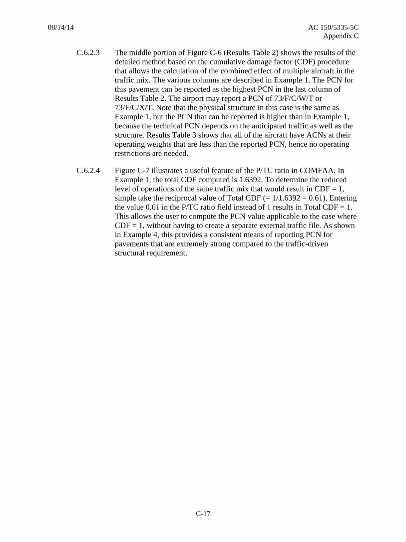
08/14/14 AC 150/5335-5C
Appendix C
C-17
The middle portion of Figure C-6 (Results Table 2) shows the results of the C.6.2.3
detailed method based on the cumulative damage factor (CDF) procedure
that allows the calculation of the combined effect of multiple aircraft in the
traffic mix. The various columns are described in Example 1. The PCN for
this pavement can be reported as the highest PCN in the last column of
Results Table 2. The airport may report a PCN of 73/F/C/W/T or
73/F/C/X/T. Note that the physical structure in this case is the same as
Example 1, but the PCN that can be reported is higher than in Example 1,
because the technical PCN depends on the anticipated traffic as well as the
structure. Results Table 3 shows that all of the aircraft have ACNs at their
operating weights that are less than the reported PCN, hence no operating
restrictions are needed.
Figure C-7 illustrates a useful feature of the P/TC ratio in COMFAA. In C.6.2.4
Example 1, the total CDF computed is 1.6392. To determine the reduced
level of operations of the same traffic mix that would result in CDF = 1,
simple take the reciprocal value of Total CDF (= 1/1.6392 = 0.61). Entering
the value 0.61 in the P/TC ratio field instead of 1 results in Total CDF = 1.
This allows the user to compute the PCN value applicable to the case where
CDF = 1, without having to create a separate external traffic file. As shown
in Example 4, this provides a consistent means of reporting PCN for
pavements that are extremely strong compared to the traffic-driven
structural requirement.

08/14/14 AC 150/5335-5C
Appendix C
C-18
Figure C-7. Detailed COMFAA Batch PCN Output – Flexible Example 2, Computed Using
the Traffic Mix from Example 1 and Modified P/TC Ratio
The following notes apply when total CDF = 1: C.6.2.5
1. For all aircraft, the thickness for total equivalent coverages (Results
Table 2, Column 3) will be the same as the COMFAA evaluation
thickness.
2. All maximum allowable gross weights in Results Table 2 will be
approximately the same as the COMFAA input gross weights and ACN
weights in Results Table 3.
3. All PCN values in Results Table 2 will be the same as the ACN values
in Results Table 3.

08/14/14 AC 150/5335-5C
Appendix C
C-19
C.6.3 Flexible Pavement Example 3.
The only change in this example from the second example is that the C.6.3.1
taxiway has a central configuration rather than parallel, such as that shown
in Figure A-1b. Figure C-8 shows the effect when the P/TC ratio changes
from 1 to 2, which results in double the number of coverages for each
aircraft in the traffic mix. As expected, the required total pavement
thickness for each aircraft in the traffic mix has increased. The B747-400
aircraft still has the greatest individual pavement thickness requirement
(31.64 inches) for its total traffic over 20 years. Note the thickness
requirements for the B747-400 now approaches the evaluation thickness
(31.9 in.).
Referring to the results Table 2 in the middle portion of the output, only the C.6.3.2
B737-300 and the A319-100 std airplanes have little impact on this
pavement’s performance. It is apparent the pavement is not adequate to
accommodate the existing traffic. As expected, changing the taxiway
system from parallel to central has lowered the PCN of the pavement by
effectively doubling traffic volume. The airport may report 68/F/C/W/T or
68/F/C/X/T. The ACN of two aircraft, the B747-400 and the B777-200 ER
exceed the pavement PCN and the airport should plan for a pavement
strengthening project or consider placing restrictions on those aircraft. The
net effect of the change in taxiway configuration from that of Example 2 is
the reduction by 5 in the PCN.

08/14/14 AC 150/5335-5C
Appendix C
C-20
Figure C-8. Detailed COMFAA Batch PCN Output – Flexible Example 3
C.6.4 Flexible Pavement Example 4.
In some cases, the pavement to be evaluated has significant excess C.6.4.1
structural capacity compared with the requirement due to forecast traffic.
This situation may arise, for example, when an overlay is added for non-
structural purposes, or in cold climates where a very thick subbase may be
needed to provide frost protection on a frost-susceptible subgrade. This
example shows a consistent way to report PCN for flexible pavements that
are extremely strong with respect to the input traffic (total CDF<<1). In
Figure C-9, the pavement from Example 1 has been strengthened with a 2-
inch overlay. Assuming a reference section with 5 inches of P-401 and 8
inches of P-209, the evaluation thickness for COMFAA is 36.4 inches
(versus 31.9 in. prior to the overlay).

08/14/14 AC 150/5335-5C
Appendix C
C-21
Figure C-10 shows the COMFAA output when PCN is computed using the C.6.4.2
evaluation thickness 36.4 in. and P/TC=1. For the overlaid pavement
subject to the forecast traffic, total CDF is much less than 1 (total CDF=
0.0355), indicating that the 20-year traffic mix causes insignificant damage
to the pavement. Similarly, the largest value of thickness for total equivalent
coverages in Results Table 2 is much less than the COMFAA evaluation
thickness at the evaluation CBR. Hence, it is necessary to use an unrealistic
allowable gross weight for the critical aircraft to compute PCN. Using the
regular COMFAA procedure without adjustment, the airport could report
PCN=97/F/C/X/T for this pavement. However, this PCN is based on an
unrealistically high allowable gross weight for the B747-400 (1,060,338
lbs.).
Figure C-9. Screen Shot of Flexible PCN Tab in COMFAA Support Spreadsheet for
Computing Equivalent Pavement Structure in Flexible Example 4. The structure is the
same as Example 1, but with a 2-inch HMA overlay, for a total P-401 thickness of 7 inches.
Fig. A2-2 Figs.A2-1&2
Flexible Pavement Convert to Convert toStructure Items P-209 P-154
P-401/3 P 403 1.6 n/a P-401/3 7.0 in.
P-306 ECONOCRTE 1.2 n/a P-306 0.0 in.
P-304 CEM. TRTD 1.2 n/a P-304 4.0 in.
P-209 Cr AGG 1.0 1.4 P-209 6.0 in.
P-208 Agg, P-211 1.0 1.2 P-208 0.0 in.
P-301 SOIL-CEM. n/a 1.2 P-301 0.0 in.
P-154 Subbase n/a 1.0 P-154 15.0 in.
0.00 0
Equivalent Thickness, mm 8.0 1
P-401/3 5.0
P-209 8.0
P-154 23.4
Total 36.4
Airport
Loc_ID
ENTER Ref.Section Requirements ABC COMFAA InputsP-401 reference t 5.00 in. Project Details Evaluation thickness t = 36.4 in.
P-209 reference t 8.00 in. Evaluation CBR = 8.0
Recommended PCN Codes: F/C/X
Subgrade CBR...
Existing
Flexible
Pavement
Layers
Reference Guidance AC 150/5335-5B App A-2
Examples
ENTER Existing
Layer Thickness
Pavement ID
5-23
Save Data
Clear Saved Data
EnglishMetric
Format Chart
P-401HMA
P-304
P-209
Base
P-154 Subbase
Subgrade CBR 8.0
Subgrade CBR 8.0
0
10
20
30
40
Existing Pavement Equivalent Pavement
Fd
ep
th f
rom
Su
rface,
in.
Zero Layer Data
Use FAA Std Factors

08/14/14 AC 150/5335-5C
Appendix C
C-22
Figure C-10. Detailed COMFAA Batch PCN Output – Flexible Example 4 (unadjusted)
The regular COMFAA procedure given in section 2.1 is most suitable when C.6.4.3
the total CDF > 0.15. When the procedure results in CDF < 0.15, as in this
example, the FAA recommends adjusting the input traffic such that the
PCN is reported for a total CDF = 0.150. Rather than modifying the
COMFAA external aircraft file, the P/TC ratio can be used to obtain total
CDF=0.150 as follows.
1. Perform a PCN Flexible Batch operation using the appropriate P/TC
ratio based on the criteria in Appendix A.
2. Note the value of Total CDF in Results Table 2.
3. Multiply the original value of P/TC ratio by the factor 0.15/Total CDF,
where Total CDF is taken from Step 2.

08/14/14 AC 150/5335-5C
Appendix C
C-23
4. Enter the new value of P/TC ratio in the P/TC field in COMFAA.
5. Repeat the PCN Flexible Batch operation with the new value of P/TC
ratio. This will result in a new Total CDF equal to or close to 0.15.
6. Note that the maximum value of P/TC ratio allowed in COMFAA is 10.
This should be sufficient in most cases. However, if the value computed
in Step 3 exceeds 10, increasing the annual departures of all input
aircraft by a factor of 10 and repeating steps 1 through 5 will generally
result in Total CDF=0.150.
Figure C-11 shows a re-analysis of the overlaid pavement using an adjusted C.6.4.4
value of the P/TC ratio equal to 1 × 0.15 / 0.0355 = 4.225. As indicated in
Results Table 2, the adjusted Total CDF = 0.15. The airport can report
PCN=84/F/C/X/T at Total CDF=0.150, based on a more reasonable
maximum allowable gross weight of the B747-400. Results Table 3 shows
that all aircraft in the existing mix operate at ACNs much lower than the
reported PCN. There is no need to report a PCN higher than 84/F/C/X/T.

08/14/14 AC 150/5335-5C
Appendix C
C-24
Figure C-11. Detailed COMFAA Batch PCN Output – Flexible Example 4 (with
adjustment to P/TC ratio to force Total CDF = 0.15)
Technical Evaluation for Rigid Pavements. C.7
C.7.1 The following list summarizes the steps for using the technical evaluation method for
rigid pavements:
Determine the traffic volume in terms of type of aircraft and number of annual
departures of each aircraft.
Determine the pavement characteristics, including subgrade soil modulus, k, and the
concrete thickness and flexural strength.
Perform the CDF calculations to determine the maximum allowable gross weight
for each aircraft on that pavement at the equivalent annual departure level.

08/14/14 AC 150/5335-5C
Appendix C
C-25
Calculate the ACN of each aircraft at its maximum allowable gross weight. Select
the PCN from the ACN data provided by all aircraft.
C.7.2 The above steps are explained in greater detail:
Determine the traffic volume in the same fashion as noted in Paragraph C.6 C.7.2.1
for flexible pavements.
1. From field data or construction drawings, document the k value of the
subgrade soil. Alternatively, conduct field or laboratory tests of the
subgrade soil in order to determine the k value. Accurate portrayal of
the subgrade k value is vital to the technical method because a small
variation in k value could result in a disproportionately large variation
in the aircraft allowable gross weight and the corresponding PCN.
2. Using COMFAA, input annual departure level for each aircraft, input
the Pass/Traffic cycle ratio (P/TC) for the runway.
3. The rigid design procedure implemented in the COMFAA program
calculates pavement thickness requirements based on the concrete edge
stress, which is in turn dependent on load repetitions of the total traffic
mix. It is therefore a requirement to convert traffic cycles or passes to
coverages repetitions by using a pass-to-coverage ratio. P/C ratios for
any aircraft on rigid pavement are calculated in the COMFAA program.
COMFAA allows the user to directly input annual departures or
coverages and will use aircraft-specific pass-to-coverage ratios to
automatically convert to coverages for calculation purposes. Since the
pass-to-coverage ratio for rigid pavement may be different than flexible
pavement, the user must enter coverages in the appropriate location for
each pavement type.
4. Obtain the pavement characteristics including the concrete slab
thickness, the concrete modulus of rupture, and average modulus, k-
value, of the subgrade. Concrete elastic modulus is set at 4,000,000 psi
and Poisson’s ratio is set at 0.15 in the COMFAA program. Accurate
subgrade modulus determination is important to the technical method,
but small variations in the modulus will not affect the PCN results in a
disproportionate manner. This is in contrast to flexible pavement
subgrade modulus in which strength variations have a significant effect
on PCN. If the pavement has a subbase course and/or stabilized
subbase layers, then the subgrade modulus is adjusted upwards in the
rigid design procedure to an equivalent value in order to account for the
improvement in support. Subgrade modulus adjustments are made
based on the FAA Westergaard method guidance included herein as
Figures B-4 through B-7 and summarized in Table B-2.
5. Using the known slab thickness modified based on overlays (see Figure
B-7), subgrade modulus modified based on improvements gained from
subbase course(s) (see Figures B-4 and B-6), P/TC ratio for the runway,
each individual aircraft’s annual departure level, and each aircraft’s

08/14/14 AC 150/5335-5C
Appendix C
C-26
parameters, compute the maximum allowable gross weight of each
aircraft using the COMFAA program in the pavement design mode.
6. Assign the subgrade modulus (k-value) to the nearest standard ACN-
PCN subgrade code. The k-value to be reported for PCN purposes is
the improved k-value seen at the top of all improved layers (k-value
directly beneath the concrete layer). Subgrade codes for k-value ranges
are found in Table 2-1.
7. The ACN of each aircraft may now be determined from the COMFAA
program. COMFAA calculates the ACN for the appropriate subgrade
codes using the allowable gross weight of each aircraft. Alternatively,
consult an “ACN versus Gross Weight” chart as published in the
manufacturer’s ACAP manual.
8. Assign the tire pressure code based on the highest tire pressure in the
traffic mix from Table 4-2. Since rigid pavements are typically able to
handle high tire pressures code W can usually be assigned.
9. The evaluation method is technical, so the code T will be used as
discussed in Paragraph 4.6.5.
10. The numerical value of the PCN is selected from the list of ACN values
resulting from Step 6 from all aircraft. If all aircraft regularly use the
airport, then select the highest ACN value and report it as the PCN. If
some of the aircraft in the traffic mix use the airport infrequently, then
further consideration must be given to the selection of the PCN. If an
aircraft that operates infrequently at the airport generates a PCN value
considerably higher than the rest of the traffic mix, then reporting the
ACN of this aircraft as the PCN will require a change to the PCN if the
aircraft’s usage changes.
Note: The recommended frequency for regularly using aircraft is
equivalent to about 20-yr coverages of 1,000.
11. The numerical value of the PCN is the same as the numerical value of
the ACN of the critical aircraft just calculated in Step 7.
12. If the allowable maximum gross weight of Step 11 is equal to or greater
than the critical aircraft operational gross weight required for the
desired pavement life, then the pavement is capable of handling the
predicted traffic for the time period established in the traffic forecast.
Accordingly, the assigned PCN determined in Step 11 is sufficient. If
the allowable gross weight from Step 11 is less than the critical aircraft
gross weight required for the desired pavement life, then the pavement
may be assigned a PCN equal to the ACN of the critical aircraft at that
gross weight, but with a reduced pavement life. Additionally, it may
then be necessary to develop a relationship of allowable gross weight
based on the assigned PCN versus pavement life. Appendix D provides
procedures on how to relate pavement life and gross weight for rigid
pavements in terms of PCN. Any overload (see Appendix D) should
be treated in terms of ACN and equivalent critical aircraft operations

08/14/14 AC 150/5335-5C
Appendix C
C-27
per individual operation. Allowances for overloads must be approved
by the airport owner on a case by case basis.
Technical Evaluation Examples for Rigid Pavements. C.8
The following four examples help explain the technical evaluation method of
determining a PCN for rigid pavements. The first example pavement is under-designed
and the traffic volume has increased to such a level that pavement life is reduced from
the original design (Total CDF > 1). The second pavement has more than adequate
strength to handle the forecasted traffic (Total CDF < 1). The third example pavement is
the same as number two, except that the aircraft generally do not obtain fuel at the
airport. The fourth example demonstrates a consistent method to report PCN when the
pavement under consideration contains significant excess structural capacity relative to
the forecast traffic (Total CDF << 1).
C.8.1 Rigid Pavement Example 1 (Total CDF>1).
An airport has a rigid (concrete surfaced) runway pavement with a subgrade C.8.1.1
k-value of 100 pci and a slab thickness of 14.5 inches, with an existing cross
section as shown in the lower right portion of Figure C-12. The concrete has
a flexural strength of 650 psi. The runway has a parallel taxiway, and
additional fuel is obtained at the airport before departure. The pavement life
is estimated to be 20 years from the original construction. The traffic shown
in Table C-6 regularly uses the pavement. Table C-7 summarizes the
existing rigid structure and the computation of the improved k-value for
input into COMFAA.
Table C-6. Input Traffic Data for Rigid Example 1
No. Aircraft Name Gross
Weight, lbs.
Percent GW
on Main
Gear
Tire
Pressure, psi
Annual
Departures
1 A300-B4 STD 364,747 94.00 216.1 1,500
2 A319-100 STD 141,978 92.60 172.6 1,200
3 B737-300 140,000 90.86 201.0 6,000
4 B747-400 877,000 93.32 200.0 1,000
5 B767-200 ER 396,000 90.82 190.0 2,000
6 B777-200 ER 657,000 91.80 205.0 1,000
7 DC8-63 330,000 96.12 196.0 3,000

08/14/14 AC 150/5335-5C
Appendix C
C-28
Table C-7. Conversion to Equivalent Pavement Structure in Rigid Example 1.
Existing Pavement Structure
Existing top-of-subgrade k-value = 100 pci
Equivalent Pavement Structure
4 inch P-403 improves k-value to 287 pci
12 inch P-209 improves k-value to 215 pci
14.5 inch concrete layer (P-501)
4 inch HMA stabilized subbase layer (P-403)
12 inch crushed aggregate subbase (P-209)
Subgrade k-value 100 pci
Concrete strength 650 psi
14.5 inch concrete layer (P-501)
k-value 287 pci
Concrete strength 650 psi
The number of load repetitions depends on the number of traffic cycles, C.8.1.2
which is calculated using Equation A-1 and then converted to coverages in
the COMFAA program. Since additional fuel is generally obtained at the
airport, and there is a parallel taxiway, P/TC = 1. This value is entered in
the appropriate field on the COMFAA main window, along with
appropriate values for the concrete strength, PCC slab thickness and the
value of improved k-value determined above, as shown in Figure C-13.

08/14/14 AC 150/5335-5C
Appendix C
C-29
Figure C-12. Screen Sot of Rigid PCN Tab in COMFAA Support Spreadsheet for
Computing Equivalent Pavement Structure in Rigid Example 1
Figure A2-7 P-401 Overlay(s) 0.0 in./2.5 0.0
Rigid Pavement Thickness P-501 14.5 in. 14.5
ThirdPoint Flexural Strength Flexural strength 650.0 psi
P-401 and/or P-403 4.0 in.
P-306 0.0 in. 4.0 287
P-304 0.0 in.
P-209 12.0 in. 12.0 215
P-208 and/or P-211 0.0 in.
P-301 0.0 in. 0.0 No Uncrushed
P-154 0.0 in.0.0 in. ##
COMFAA Inputs Subgrade k-value 100.0 lb/in^330.50 287.00
k-value = 287.0 lb/in^3
Rigid Pavement t = 14.5 in.
Flexural strength = 650.0 psi
Recommended PCN Codes: R/B/W
Enter Project Details
English
Arpt LOC-ID
IOU
Pavement ID
Rwy 5-23
Examples
Figure A2-6, default maximum k-value =
500 lb/in^3. (135.7 MN/m^3) OR input k-
value if greater.
Combined Top and Bottom Figure A2-5.
Ref. AC 150/5335-5B Appendix A-2 Rigid
Pavement Structure Items
Overlay to P-501,
2.5 to 1
Existing Rigid
Pavement Layers
Foundation k=
Maximum k-
Below or Input k
Evaluation
Layer
Thickness
Improved\ k-
value
ENTER Existing
Layer Thickness
P-501 flex strength =
650.0 psi
P-501 flex strength =
650.0 psi
P-401 Stabilized
k=287.0
P-209Crushed k=215.0
0
5
10
15
20
25
Existing Pavement Equivalent Pavement
Dep
th f
rom
Su
rface, i
n.
Clear Saved Data
Save Data
English
Metric
Zero Layer Data
Format Chart

08/14/14 AC 150/5335-5C
Appendix C
C-30
Figure C-13. Screen Shot of COMFAA Main Screen Showing the Required Inputs for
Rigid Example 1

08/14/14 AC 150/5335-5C
Appendix C
C-31
Figure C-14. Detailed COMFAA Batch PCN Output – Rigid Example 1

08/14/14 AC 150/5335-5C
Appendix C
C-32
Figure C-14 shows the shows the results of the COMFAA Batch PCN Rigid C.8.1.3
calculations. The top portion of Figure C-14 (Results Table 1) shows the
required thickness using the thickness design in accordance with the FAA
Westergaard method for a concrete pavement with subgrade k-value of 287
pci. Note that the thickness requirements for several traffic aircraft are
within about an inch of the evaluation pavement thickness (14.5 in). When
the thickness of individual aircraft is close to the evaluation thickness most
likely the thickness needed to accommodate the fleet will be more than the
evaluation thickness resulting in a PCN of the most demanding aircraft
being less than its ACN. The middle portion of Figure C-14 shows the
results of the detailed method based on the cumulative damage factor (CDF)
procedure that allows the calculation of the combined effect of multiple
aircraft in the traffic mix. The numerical values in the CDF column
represent damage to a 14.5-in. thick rigid pavement on an equivalent
subgrade with k = 287 pci for each aircraft in the list. The total CDF
represents the combined damage from this traffic. Total CDF exceeds 1 in
this case, indicating that the pavement is under-designed for the given
traffic. Taking each aircraft in turn as the critical aircraft, the program
computes total equivalent coverages (based on a CDF analysis), the
corresponding thickness for the total equivalent coverages (which is greater
than the required thickness for the individual aircraft shown in Results
Table 1), and a maximum allowable gross weight. The ACN of the aircraft
at the maximum allowable gross weight, at the appropriate ICAO standard
k-value, is computed and reported in Results Table 2 as the PCN (last
column). The PCN for this pavement can be reported as the highest PCN in
the PCN column. Based on the information in Figure C-14, the airport may
report a PCN of 61/R/B/W/T. Note that the W code should be used for the
tire pressure category because this is a rigid pavement.
Referring to the CDF calculation results shown in Results Table 2 of Figure C.8.1.4
C-14, the A319-100 std and the B777-200 contribute the least to the
cumulative damage on this pavement. However, the required thickness in
Column 3 of Results Table 2 is consistently greater than the evaluation
thickness. This indicates that the pavement does not have sufficient strength
to accommodate all existing traffic. The ACNs (Results Table 3) for several
aircraft exceed the pavement PCN and the airport should plan for a
pavement strengthening project or consider placing restrictions on some
aircraft.
The following notes apply when total CDF > 1: C.8.1.5
1. At least one ACN value in Results Table 3 will be greater than all of the
PCN values in Results Table 2.
2. For all aircraft, the thickness for total equivalent coverages (Column 3
in Results Table 2) will exceed the evaluation pavement thickness for
the input subgrade k-value.

08/14/14 AC 150/5335-5C
Appendix C
C-33
3. One aircraft in the list will have the greatest thickness requirement for
total equivalent coverages, and this “PCN thickness” value will be less
than at least one ACN thickness value in Results Table 3.
4. A project to strengthen the pavement to support forecast traffic is
required.
5. An overload analysis should be performed.
C.8.2 Rigid Pavement Example 2 (Total CDF<1).
This second example has the same traffic and other input parameters as the C.8.2.1
first, except the slab thickness is increased by 0.5 inches to 15 inches. As
shown in Figure C-15, the equivalent k-value is the same as Example 1.

08/14/14 AC 150/5335-5C
Appendix C
C-34
Figure C-15. Screen Shot of Rigid PCN Tab in COMFAA Support Spreadsheet for
Computing Equivalent Pavement Structure in Rigid Example 2
Figure A2-7 P-401 Overlay(s) 0.0 in./2.5 0.0
Rigid Pavement Thickness P-501 15.0 in. 15.0
ThirdPoint Flexural Strength Flexural strength 650.0 psi
P-401 and/or P-403 4.0 in.
P-306 0.0 in. 4.0 287
P-304 0.0 in.
P-209 12.0 in. 12.0 215
P-208 and/or P-211 0.0 in.
P-301 0.0 in. 0.0 No Uncrushed
P-154 0.0 in.0.0 in. ##
COMFAA Inputs Subgrade k-value 100.0 lb/in^331.00 287.00
k-value = 287.0 lb/in^3
Rigid Pavement t = 15.0 in.
Flexural strength = 650.0 psi
Recommended PCN Codes: R/B/W
Enter Project Details
English
Arpt LOC-ID
IOU
Pavement ID
Rwy 5-23
Examples
Figure A2-6, default maximum k-value =
500 lb/in^3. (135.7 MN/m^3) OR input k-
value if greater.
Combined Top and Bottom Figure A2-5.
Ref. AC 150/5335-5B Appendix A-2 Rigid
Pavement Structure Items
Overlay to P-501,
2.5 to 1
Existing Rigid
Pavement Layers
Foundation k=
Maximum k-
Below or Input k
Evaluation
Layer
Thickness
Improved\ k-
value
ENTER Existing
Layer Thickness
P-501 flex strength =
650.0 psi
P-501 flex strength =
650.0 psi
P-401 Stabilized
k=287.0
P-209Crushed k=215.0
0
5
10
15
20
25
Existing Pavement Equivalent Pavement
Dep
th f
rom
Su
rface, i
n.
Clear Saved Data
Save Data
English
Metric
Zero Layer Data
Format Chart

08/14/14 AC 150/5335-5C
Appendix C
C-35
Figure C-16. Detailed COMFAA Batch PCN Output – Rigid Example 2
Figure C-16 shows the detailed results from COMFAA. In this case it is C.8.2.2
seen that the pavement has sufficient strength to support the traffic mix.
Results Table 1 (top portion of Figure C-16) shows the required thickness
for each aircraft according to the FAA Westergaard method for a concrete
pavement with subgrade k-value of 287 pci. Note that the individual
thickness requirements for all aircraft are less than the evaluation pavement
thickness of 15.0 inches. Since thickness required for individual aircraft are
all less than the evaluation thickness the pavement should have sufficient
capacity to accommodate the entire fleet. However, the results from the
cumulative damage factor (CDF) procedure are needed for confirmation.

08/14/14 AC 150/5335-5C
Appendix C
C-36
Results Table 2 (middle portion of Figure C-16) shows the results of the C.8.2.3
detailed method based on the CDF procedure that allows the calculation of
the combined effect of multiple aircraft in the traffic mix. Each aircraft in
turn is treated as the critical aircraft. For each aircraft, the CDF analysis
calculates a maximum allowable gross weight, equivalent coverage level,
and corresponding thickness at the evaluation thickness (15.0 in.) and
support conditions (287 pci). The total CDF is less than 1 (0.7931) in this
case, indicating that there is adequate strength to handle the forecast traffic.
The PCN for this pavement can be reported as the highest PCN in the PCN
column. Based on the information in Figure C-16, the airport may report a
PCN of 66/R/B/W/T. Note that the W code should be used for the tire
pressure category because this is a rigid pavement.
Values in Results Table 3 are identical to the corresponding values in C.8.2.4
Results Table 3 for Example 1. This is because the operating aircraft load
data are the same in both examples. All aircraft in the traffic mix have
ACNs at their operating weights less than the reported PCN, hence no
operating restrictions are needed.
The following notes apply when total CDF < 1: C.8.2.5
1. For all aircraft, the thickness for total equivalent coverages (Results
Table 2, Column 3) will be the less than the COMFAA evaluation
thickness.
2. All maximum allowable gross weights in Results Table 2 will be
greater than the corresponding COMFAA input gross weights in
Results Table 1 and the ACN weights in Results Table 3.
3. At least one of the PCN values in Results Table 2 will be greater than
all ACN values in Results Table 3.
C.8.3 Rigid Pavement Example 3.
This example is the same as Example 2, except that the taxiway has a C.8.3.1
central configuration rather than parallel, such as that shown in Figure A-
1b. It is still assumed that additional fuel is obtained before departure.
Referring to Table C-9, the P/TC ratio changes from 1 to 2. The change
results in double the number of coverages for each aircraft in the traffic mix
as shown in Results Table 1 of Figure C-17. As expected, the required total
pavement thickness for each aircraft in the traffic mix has increased. Note
that the thickness requirements for several traffic aircraft are within about
an inch of the evaluation pavement thickness (15.0 in), indicating that the
pavement strength may be inadequate for the increased number of
coverages.
Column 3 of Results Table 2 shows that each aircraft requires a thickness C.8.3.2
greater than the evaluation thickness when using the CDF method. It is
apparent the pavement is not adequate to accommodate double the
coverages of the existing traffic. As expected, changing the taxiway system
from parallel to central has lowered the PCN of the pavement. The airport

08/14/14 AC 150/5335-5C
Appendix C
C-37
may report 60/R/B/W/T. The ACN of two aircraft exceed the pavement
PCN and the airport should plan for a pavement strengthening project or
consider placing restrictions on those aircraft. The net effect of the change
in taxiway configuration from that of Example 2 is the reduction in PCN
by 6.
As an alternate way of looking at the effect of a parallel versus central C.8.3.3
taxiway effects, consider how the pavement life would change instead of
the PCN. If the reported PCN from this example were to remain at
66/R/B/W/T, then the pavement life would be reduced by 50%. This is due
to the change in the P/TC ratio, which effectively doubled the number of
loadings. A similar effect would be noticed if fuel was not obtained at the
airport. With a P/TC ratio of 3, the PCN is reduced further and the
pavement life would be one-third the pavement life of the pavement with
the original traffic assumptions given for example 2.

08/14/14 AC 150/5335-5C
Appendix C
C-38
Figure C-17. Detailed COMFAA Batch PCN Output – Rigid Example 3
C.8.4 Rigid Pavement Example 4 (Total CDF<<1).
This example demonstrates a consistent method of reporting PCN for rigid C.8.4.1
pavements that are extremely strong with respect to the input traffic. This
situation may arise, for example, where an existing rigid pavement is given
a HMA overlay for non-structural reasons. Assume that the rigid pavement
in Example 1 receives a 5-in P-401 HMA overlay. Using the Rigid PCN tab
of the COMFAA Support Spreadsheet (Figure C-18), the evaluation
thickness is 16.5 inches versus 14.5 inches prior to the overlay. The traffic
for this example is given in Table C-7, and all other input values are as in
Example 1.

08/14/14 AC 150/5335-5C
Appendix C
C-39
Table C-8. Input Traffic Data for Rigid Example 4
No. Aircraft Name Gross
Weight, lbs.
Percent GW
on Main
Gear
Tire
Pressure, psi
Annual
Departures
1 A300-B4 STD 364,747 94.00 216.1 400
2 A319-100 STD 141,978 92.60 172.6 300
3 B737-300 140,000 90.86 201.0 1,500
4 B747-400 877,000 93.32 200.0 200
5 B767-200 ER 396,000 90.82 190.0 500
6 B777-200 ER 657,000 91.80 205.0 320
7 DC8-63 330,000 96.12 196.0 750

08/14/14 AC 150/5335-5C
Appendix C
C-40
Figure C-18. Screen Shot of Rigid PCN Tab in COMFAA Support Spreadsheet for
Computing Equivalent Pavement Structure in Rigid Example 4
Figure A2-7 P-401 Overlay(s) 5.0 in./2.5 2.0
Rigid Pavement Thickness P-501 14.5 in. 16.5
ThirdPoint Flexural Strength Flexural strength 650.0 psi
P-401 and/or P-403 4.0 in.
P-306 0.0 in. 4.0 287
P-304 0.0 in.
P-209 12.0 in. 12.0 215
P-208 and/or P-211 0.0 in.
P-301 0.0 in. 0.0 No Uncrushed
P-154 0.0 in.0.0 in. ##
COMFAA Inputs Subgrade k-value 100.0 lb/in^332.50 287.00
k-value = 287.0 lb/in^3
Rigid Pavement t = 16.5 in.
Flexural strength = 650.0 psi
Recommended PCN Codes: R/B/X
Enter Project Details
English
Arpt LOC-ID
IOU
Pavement ID
Rwy 5-23
Examples
Figure A2-6, default maximum k-value =
500 lb/in^3. (135.7 MN/m^3) OR input k-
value if greater.
Combined Top and Bottom Figure A2-5.
Ref. AC 150/5335-5B Appendix A-2 Rigid
Pavement Structure Items
Overlay to P-501,
2.5 to 1
Existing Rigid
Pavement Layers
Foundation k=
Maximum k-
Below or Input k
Evaluation
Layer
Thickness
Improved\ k-
value
ENTER Existing
Layer Thickness
Overlay
P-501 flex strength =
650.0 psi
P-501 flex strength =
650.0 psi
P-401
Stabilized k=287.0
0
5
10
15
20
25
Existing Pavement Equivalent Pavement
Dep
th f
rom
Su
rface, i
n.
Clear Saved Data
Save Data
English
Metric
Zero Layer Data
Format Chart

08/14/14 AC 150/5335-5C
Appendix C
C-41
Figure C-19. Detailed COMFAA Batch PCN Output – Rigid Example 4 (unadjusted)
Figure C-19 shows the COMFAA output when PCN is computed using the C.8.4.2
evaluation thickness 16.5 in. and P/TC=1. For the overlaid pavement
subject to the forecast traffic, total CDF is much less than 1 (total CDF=
0.0331), indicating that the 20-year traffic mix causes insignificant damage
to the pavement. Similarly, the largest value of thickness for total equivalent
coverages in Results Table 2 is much less than the COMFAA evaluation
thickness at the evaluation k-value. Hence, it may be necessary to use an
unrealistic allowable gross weight for the critical aircraft to compute PCN.
Using the regular COMFAA procedure without adjustment, the airport
could report PCN=99/R/B/X/T for this pavement. However, this PCN is
based on an unrealistically high allowable gross weight for the B747-400
(1,202,217 lbs.).

08/14/14 AC 150/5335-5C
Appendix C
C-42
The regular COMFAA procedure given in section 2.3 is most suitable when C.8.4.3
the total CDF > 0.15. When the procedure results in CDF < 0.15, as in this
example, the FAA recommends adjusting the input traffic such that the
PCN is reported for a total CDF = 0.150. Rather than modifying the
COMFAA external aircraft file, the P/TC ratio can be used to obtain total
CDF=0.150 as follows.
1. Perform a PCN Rigid Batch operation using the appropriate P/TC ratio
based on the criteria in Appendix A.
2. Note the value of Total CDF in Results Table 2.
3. Multiply the original value of P/TC ratio by the factor 0.15/Total CDF,
where Total CDF is taken from Step 2.
4. Enter the new value of P/TC ratio in the P/TC field in COMFAA.
5. Repeat the PCN Rigid Batch operation with the new value of P/TC
ratio. This will result in a new Total CDF equal to or close to 0.15.
6. Note that the maximum value of P/TC ratio allowed in COMFAA is 10.
This should be sufficient in most cases. However, if the value computed
in Step 3 exceeds 10, increasing the annual departures of all input
aircraft by a factor of 10 and repeating steps 1 through 5 will generally
result in Total CDF=0.150.
Figure C-20 shows a re-analysis of the overlaid pavement using an adjusted C.8.4.4
value of the P/TC ratio equal to 1 × 0.15 / 0.0331 = 4.532. As indicated in
Results Table 2, the adjusted Total CDF = 0.15. The airport can report
PCN=83/R/B/X/T or 83/R/B/W/T at Total CDF=0.150, based on a more
reasonable maximum allowable gross weight of the B777-200 ER. Results
Table 3 shows that all aircraft in the existing mix operate at ACNs much
lower than the reported PCN. There is no need to report a PCN higher
than 83.

08/14/14 AC 150/5335-5C
Appendix C
C-43
Figure C-20. Detailed COMFAA Batch PCN Output – Rigid Example 4 (with adjustment
to P/TC ratio to force Total CDF = 0.15)

08/14/14 AC 150/5335-5C
Appendix C
C-44
Page Intentionally Blank

08/14/14 AC 150/5335-5C
Appendix D
D-1
APPENDIX D. PAVEMENT OVERLOAD EVALUATION BY THE ACN-PCN SYSTEM
ICAO Pavement Overload Evaluation Guidance. D.1
D.1.1 In the life of a pavement, it is possible that either the current or the future traffic will
load the pavement in such a manner that the assigned pavement rating is exceeded.
ICAO provides a simplified method to account for minor pavement overloading in
which the overloading may be adjusted by applying a fixed percentage to the existing
PCN.
D.1.2 The ICAO procedure for overload operations is based on minor or limited traffic having
ACNs that exceed the reported PCN. Loads that are larger than the defined PCN will
shorten the pavement design life, while smaller loads will use up the life at a reduced
rate. With the exception of massive overloading, pavements do not suddenly or
catastrophically fail. As a result, occasional minor overloading is acceptable with only
limited loss of pavement life expectancy and relatively small acceleration of pavement
deterioration.
D.1.3 The following guidelines are recommended when evaluating overloads:
For flexible pavements, occasional traffic cycles by aircraft with an ACN not
exceeding 10 percent above the reported PCN should not adversely affect the
pavement. For example, a pavement with PCN=60 can support some limited traffic
of aircraft with ACN=66.
For rigid or composite pavements, occasional traffic cycles by aircraft with an ACN
not exceeding 5 percent above the reported PCN should not adversely affect the
pavement. For example, a pavement with PCN=60 can support some limited traffic
of aircraft with ACN=63.
The annual number of overload traffic cycles should not exceed approximately 5
percent of the total annual aircraft traffic cycles. There is no exact guidance for
choosing a number of operations that represents 5 percent. For consistency, the
FAA recommends using 500 coverages of aircraft with ACN=1.1xPCN for flexible
pavements ACN=1.05xPCN for rigid pavements. The PCN is 10,000 coverages of
an aircraft with a derived ACN=PCN when CDF=1, five percent of this total
equivalent operations is 500 coverages.
Overloads should not normally be permitted on pavements already exhibiting signs
of distress, during periods of thaw following frost penetration, or when the strength
of the pavement or its subgrade could be weakened by water.
When overload operations are conducted, the airport owner should regularly inspect
the pavement condition. Periodically the airport owner should review the criteria
for overload operations. Excessive repetition of overloads can cause in a significant
reduction in pavement life or accelerate when a pavement will require a major
rehabilitation.

08/14/14 AC 150/5335-5C
Appendix D
D-2
D.1.4 These criteria provide consistent, repeatable process the airport owner can use to
monitor the impact of these overload operations on the pavement in terms of pavement
life reduction or increased maintenance requirements. This appendix discusses methods
for making overload allowances for both flexible and rigid pavements that will clearly
indicate these effects and will give the authority the ability to determine the impact both
economically and in terms of pavement life.
Overload Guidance. D.2
D.2.1 The overload evaluation guidance in this appendix applies primarily to flexible and
rigid pavements that have PCN values that were established by the technical method.
Pavements that have ratings determined by the using aircraft method can use the
overload guidelines provided very frequent pavement inspection procedures are
followed. The procedures presented here rely on the COMFAA program.
D.2.2 The adjustments for pavement overloads start with the assumption that some of the
aircraft in the traffic mix have ACNs that exceed the PCN. If the steps outlined in
Appendix C have been followed for the technical method, then most of the necessary
data already exists to perform an examination of overloading.
D.2.3 The recommended PCN is not adequate for the traffic mix when the Total CDF>1.
Airports have three options when evaluating what pavement strength rating to publish:
1. Let the PCN remain as derived from the technical evaluation method, but retain
local knowledge that there are some aircraft in the traffic mix that can be allowed to
operate with ACNs that exceed the published PCN or at a reduced weight to not
exceed the PCN.
2. Provide for an increased PCN by adding an overlay or by reconstruction to
accommodate aircraft with higher ACNs.
3. Adjust the PCN upward to that of the aircraft with the highest ACN, but recognize
the need to expect possible severe maintenance. This will result in earlier and
increased costs for reconstruction or overlay projects.
Adjustments for Flexible Pavement Overloads. D.3
D.3.1 First Option.
The first option requires that the airport owner is constantly aware of the composition of
the entire traffic mix in terms of operating gross weights and loading frequency. If the
traffic mix has changes that affect the factors involved in developing a technically based
PCN, then the PCN will need to be adjusted to reflect the changes. The airport
authority will also have to internally make allowance for or prevent aircraft operations
that exceed the PCN. A consistent method to determine when aircraft ACN and
frequency exceed allowable overloads is presented in the following paragraphs.

08/14/14 AC 150/5335-5C
Appendix D
D-3
For flexible pavement example Total CDF>1. The B-747-400 has the D.3.1.1
highest CDF-PCN combination. The traffic aircraft with the highest CDF-
PCN combination is the basis for overload analysis. The PCN=68.9 and the
traffic mix is equivalent to 10,000 coverages of a B747-400 with a gross
weight, MGW=847,310 lbs. on a 37.8 in. pavement with CBR = 6. Aircraft
with PCN=(1.1x68,9)=75.8 can operate at 500 coverages total with minimal
impact on the load carrying capacity. The gross weight of a B747-400 at
ACN=75.8 is the MGW from COMFAA using 10,000 coverages, 39.65 in.,
and CBR=6.
Figure D-1. CDF-PCN Results for the B-747-100 – Flexible Pavement Overload
Option One
COMFAA MGW results at 39.65 in., CBR=6 for the B747-400 traffic D.3.1.2
aircraft is MGW=901,739 lbs. COMFAA Batch ACN results confirm that
increasing MGW from 847,310 lbs. to 901,739 lbs. increases ACN 10
percent.
Figure D-2. COMFAA Batch ACN Results – Flexible Pavement Overload Option One

08/14/14 AC 150/5335-5C
Appendix D
D-4
COMFAA PCN results with 500 coverages of the aircraft with 10 percent D.3.1.3
higher ACN confirms minor impact on this flexible pavement. However,
the PCN=74.8, which is less than ACN=75.8. Overloads are occurring at
the input traffic gross weight and frequency.
Figure D-3. COMFAA Batch PCN Results – Flexible Pavement Overload Option One
D.3.2 Second Option.
The second option alleviates the problems discussed for the first option, but it does
require additional expense to bring the pavement up to the strength required by the
combination of aircraft in the traffic mix. The two inch overlay increases the PCN from
68.9 to 96.9, providing added pavement strength allows operations at current levels and
weights until the overlay project is programmed.
Figure D-4. COMFAA PCN Results – Flexible Pavement Overload Option Two
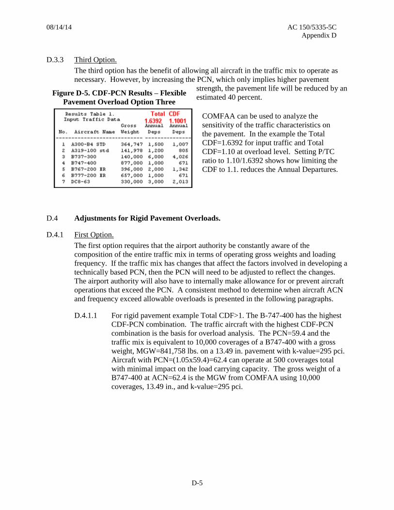
08/14/14 AC 150/5335-5C
Appendix D
D-5
D.3.3 Third Option.
The third option has the benefit of allowing all aircraft in the traffic mix to operate as
necessary. However, by increasing the PCN, which only implies higher pavement
strength, the pavement life will be reduced by an
estimated 40 percent.
COMFAA can be used to analyze the
sensitivity of the traffic characteristics on
the pavement. In the example the Total
CDF=1.6392 for input traffic and Total
CDF=1.10 at overload level. Setting P/TC
ratio to 1.10/1.6392 shows how limiting the
CDF to 1.1. reduces the Annual Departures.
Adjustments for Rigid Pavement Overloads. D.4
D.4.1 First Option.
The first option requires that the airport authority be constantly aware of the
composition of the entire traffic mix in terms of operating gross weights and loading
frequency. If the traffic mix has changes that affect the factors involved in developing a
technically based PCN, then the PCN will need to be adjusted to reflect the changes.
The airport authority will also have to internally make allowance for or prevent aircraft
operations that exceed the PCN. A consistent method to determine when aircraft ACN
and frequency exceed allowable overloads is presented in the following paragraphs.
For rigid pavement example Total CDF>1. The B-747-400 has the highest D.4.1.1
CDF-PCN combination. The traffic aircraft with the highest CDF-PCN
combination is the basis for overload analysis. The PCN=59.4 and the
traffic mix is equivalent to 10,000 coverages of a B747-400 with a gross
weight, MGW=841,758 lbs. on a 13.49 in. pavement with k-value=295 pci.
Aircraft with PCN=(1.05x59.4)=62.4 can operate at 500 coverages total
with minimal impact on the load carrying capacity. The gross weight of a
B747-400 at ACN=62.4 is the MGW from COMFAA using 10,000
coverages, 13.49 in., and k-value=295 pci.
Figure D-5. CDF-PCN Results – Flexible
Pavement Overload Option Three

08/14/14 AC 150/5335-5C
Appendix D
D-6
Figure D-6. CDF-PCN Results for the B-747-400 – Rigid Pavement Overload Option One
COMFAA MGW results at 13.8 in., and k-value=295 pci for the B747-400 D.4.1.2
traffic aircraft is MGW=871,000 lbs. COMFAA Batch ACN results
confirm that increasing MGW from 841,758 lbs. to 871,000 lbs. increases
ACN 5 percent.
Figure D-7. COMFAA Batch ACN Results – Rigid Pavement Overload Option One

08/14/14 AC 150/5335-5C
Appendix D
D-7
COMFAA PCN results with 500 coverages of the aircraft with 5 percent D.4.1.3
higher ACN confirms minor impact on this rigid pavement. However, the
PCN=62.0, which is less than ACN=63.6. Overloads are occurring at the
input traffic gross weight and frequency.
Figure D-8. COMFAA PCN Results – Rigid Pavement Overload Option One
D.4.2 Second Option.
The second option alleviates the problems discussed for the first option, but it does
require additional expense to bring the pavement up to the strength required by the
combination of aircraft in the traffic mix. The five-inch flexible overlay is converted to
an additional two inches of rigid pavement. The PCN increases from PCN=63.6 to
PCN= 98.1. Providing added pavement strength allows operations at current levels and
weights until the overlay project is programmed.
Figure D-9. COMFAA PCN Results –Rigid Pavement Overload Option Two

08/14/14 AC 150/5335-5C
Appendix D
D-8
D.4.3 Third Option.
The third option has the benefit of allowing all aircraft in the traffic mix to operate as
necessary. However, by increasing the PCN, which only implies higher pavement
strength, the pavement life will be
reduced by an estimated 40 percent.
COMFAA can be used to analyze
the sensitivity of the traffic
characteristics on the pavement.
In the example the Total
CDF=1.5402 for input traffic and
Total CDF=1.0543 at overload
level. Setting P/TC ratio to
1.0543/1.5402 shows how the
additional damage is expressed as
an Annual Departure reduction.
Figure D-10. COMFAA PCN Results – Rigid
Pavement Overload Option Three

08/14/14 AC 150/5335-5C
Appendix E
E-1
APPENDIX E. REPORTING CHANGES TO CERTAIN AIRPORT RUNWAY DATA ELEMENTS
This Advisory Circular affects the following airport runway data.
Allowable Gross Weight. E.1
Aircraft weight data is reported using this AC based upon the PCN calculated for the
pavement being evaluated. With PCN there is not a “design aircraft”.
E.1.1 Source of Data.
Runway weight bearing capacity data must be submitted through the FAA Airports
Division Regional Office (RO) or FAA Airports District Office (ADO). Information is
submitted electronically to the FAA Air Traffic Aeronautical Information Services for
publication in FAA Flight Information manuals using the secure web site 5010WEB,
monitored by GCR & Associates on behalf the FAA. Currently this data base accepts
gross aircraft weight data for single wheel landing gear (S), dual wheel landing gear
(D), dual tandem landing gear (2D) and double dual tandem wheel type landing gear
(2D/2D2). All other gear types may only be reported with the PCN. Note when
reporting PCN it must be all five elements, e.g. 73/F/C/W/T. All changes to Runway
Weight Bearing Capacity data must be submitted through the FAA. State airport
inspectors may not submit changes to Runway Weight Bearing Capacity Data directly
to Aeronautical Information Services for publication. Instead, they must submit the
data changes to the RO and ADO for validation, and in turn, the RO or ADO submits
changes to Runway Weight Bearing Capacity Data electronically to Aeronautical
Information Services using the steps enumerated above on behalf of the State Aviation
Agency.
E.1.2 Reporting Allowable Gross Weight.
The allowable gross aircraft weight for each gear configuration that may utilize the
subject runway is published on FAA Form 5010. In addition a PCN number should also
be published for each Runway at the airport. Note the PCN ‘number’ to report is the
entire PCN string of Pavement Classification Number combined with subgrade
category, tire pressure, and method of calculation. A list of PCN-based maximum
gross weights for reporting Runway Weight Bearing Capacity Data has been developed.
The listing is posted on the FAA website with this AC. Local experience can be
considered to report a lower weight, but higher weights are not recommended.
Pavement Classification Number (PCN). E.2
E.2.1 Source of Data.
The source for Pavement Classification Number (PCN) data is the airport operator.
FAA Part 139 airport inspectors and State non-Part 139 airport inspectors are instructed
to request PCN data from the airport manager as part of the manager interview before

08/14/14 AC 150/5335-5C
Appendix E
E-2
an airport inspection. If the airport manager has PCN data, the inspector may accept the
data for immediate publication in flight information publications; however, if the airport
manager does not have PCN data, then the inspector has no PCN data available for
publication.
E.2.2 Reporting PCN.
For purposes of airport runway data elements generally published on FAA Form 5010,
Airport Master Record, the PCN is a number that expresses the load-carrying capacity
of a pavement based on all aircraft traffic that regularly operates on the pavement. The
PCN determined earlier (see Appendices 1 through 3) is the PCN to report.
Assigning Aircraft Gross Weight Data. E.3
E.3.1 Tables E-1 and E-2 summarize the process used to assign allowable aircraft gross
weight. Table E-1 shows the flexible ACNs. Table E-2 shows the rigid ACNs.
Allowable gross weight is based on aircraft gear configuration as issued in FAA Order
5300.7, Standard Naming Convention for Aircraft Landing Gear Configurations
(October 6, 2005), coupled with tire pressure and wheel spacing ranges. The ACN for
these standard aircraft results in a recommended maximum gross weight for Runway
Weight Bearing Capacity. See Chapter 3 for instructions for using the COMFAA
software to determine ACN values under certain conditions. The COMFAA external
file will be posted on the FAA website.

08/14/14 AC 150/5335-5C
Appendix E
E-3
Table E-1. Flexible ACN Data Used to Establish Allowable Gross Weight

08/14/14 AC 150/5335-5C
Appendix E
E-4
Table E-2. Rigid ACN Data Used to Establish Allowable Gross Weight
E.3.2 The data in the tables were used to develop a list of maximum gross weights for
Runway Weight Bearing Capacity Data. The listings that correlates gross weights with
known PCN values for flexible and rigid pavement (see Appendix F) provide
recommended maximum gross weights based on PCN determination.

08/14/14 AC 150/5335-5C
Appendix E
E-5
E.3.3 There will be cases where the gross weight of an aircraft exceeds the gross weight in
Tables E-1 and E-2 for a reported PCN determined using the procedures in Appendices
1 through 3. The values in the tables are not as accurate as the gross weights associated
with the ACN assigned by the aircraft manufacturer. The reported PCN is the basis for
data in the tables, and the airport manager should rely on the reported PCN rather than
the gross weight data in the table when the ACN of the departing or landing aircraft is
known.
E.3.4 Table E-3 shows the format of the list and brief instructions on its use. The first
example shown in the table is for a pavement that supports single, dual, and dual
tandem wheel gear aircraft, and the airport can report a PCN of 30 with subgrade
category B support. At the intersection of the PCN value with the gear types SW, DW,
and DTWS and Subgrade Support Category B, 76,000 pounds is the maximum
allowable gross weight for single wheel aircraft, 115,000 pounds is the maximum
allowable gross weight for dual wheel aircraft, and 215,000 pounds is the maximum
allowable gross weight for dual tandem wheel aircraft. Local experience can be
considered to use a lower weight, but higher weights are not recommended.
Table E-3. Excerpt From Listing of Maximum Gross Weight Data

08/14/14 AC 150/5335-5C
Appendix E
E-6
E.3.5 The second example in the table is for a pavement that supports aircraft with single and
dual wheel gear configurations. The pavement has a PCN of 43/R/B/W/T. The gross
weights at the intersection of the PCN value for a B category subgrade with each gear
type is between PCN values 40 and 45. Straight line interpolation between values is
recommended. Single wheel gross weight is 107,000 pounds. Dual wheel gross weight
is 152,000. Local experience can be considered to use lower weights, but higher
weights are not recommended.

08/14/14 AC 150/5335-5C
Appendix F
F-1
APPENDIX F. MAXIMUM AIRCRAFT GROSS WEIGHT TABLES FOR FAA FORM 5010 REPORTING BASED ON PCN DETERMINATION
Table F-1. Subgrade Strength Category A
FLEXIBLE PCN Subgrade Category A RIGID PCN Subgrade Category A
Aircraft gross weight (1,000's lbs): Subgrade Category A
SW DW DTW DDTW SW DW DTW DDTW
A(15) A(15) A(15) A(15) A(552) A(552) A(552) A(552)
PCN
3 15 --- --- --- --- --- --- ---
4 18 --- --- --- 14 --- --- ---
5 21 --- --- --- 17 --- --- ---
6 25 40 --- --- 21 --- --- ---
7 27 45 --- --- 23 35 --- ---
8 30 45 --- --- 27 40 --- ---
9 33 50 --- --- 30 45 --- ---
10 36 55 95 --- 32 50 100 ---
12 41 60 110 --- 38 55 115 ---
13 44 65 120 --- 41 60 120 ---
14 47 65 125 --- 43 60 125 ---
15 49 70 130 --- 46 65 135 ---
16 51 75 140 --- 49 65 140 ---
17 53 75 145 --- 51 70 145 ---
18 56 80 150 --- 53 70 150 ---
19 58 80 160 --- 56 75 155 ---
20 60 85 165 --- 58 80 160 ---
25 71 100 195 --- 70 90 190 ---
30 81 120 230 --- 81 110 220 ---
34 89 140 260 --- 89 125 245 625

08/14/14 AC 150/5335-5C
Appendix F
F-2
FLEXIBLE PCN Subgrade Category A RIGID PCN Subgrade Category A
Aircraft gross weight (1,000's lbs): Subgrade Category A
SW DW DTW DDTW SW DW DTW DDTW
A(15) A(15) A(15) A(15) A(552) A(552) A(552) A(552)
PCN
35 91 145 265 630 92 130 250 635
40 102 165 295 700 102 150 275 700
45 111 185 335 770 112 165 310 765
48 116 195 355 810 116 175 335 800
49 --- 195 360 820 --- 175 340 810
50 --- 200 370 835 --- 180 350 825
55 --- 220 410 900 --- 195 385 880
60 --- 240 460 960 --- 210 425 930
65 --- --- 520 1015 --- 225 485 980
70 --- --- --- 1065 --- 240
--- 1030
71 --- --- --- 1075 --- 240 --- 1040
72 --- --- --- 1085 --- --- --- 1050
75 --- --- --- --- --- --- --- 1080
Note: When the PCN falls between two values, use straight line interpolation to determine the allowable gross weight for the gear types.
Table F-2. Subgrade Strength Category B
FLEXIBLE PCN Subgrade Category B RIGID PCN Subgrade Category B
Airplane gross weight (1,000's lbs): Subgrade Category B
SW DW DTW DDTW SW DW DTW DDTW
B(10) B(10) B(10) B(10) B(295) B(295) B(295) B(295)
PCN
3 15 --- --- --- 14 --- --- ---
6 23 35 --- --- 22 --- --- ---
7 26 40 --- --- 25 35 --- ---
8 29 45 100 --- 28 40 --- ---
9 32 50 105 --- 32 45 --- ---
10 34 50 110 --- 34 50 --- ---

08/14/14 AC 150/5335-5C
Appendix F
F-3
FLEXIBLE PCN Subgrade Category B RIGID PCN Subgrade Category B
Airplane gross weight (1,000's lbs): Subgrade Category B
SW DW DTW DDTW SW DW DTW DDTW
B(10) B(10) B(10) B(10) B(295) B(295) B(295) B(295)
PCN
11 36 55 120 --- 37 50 100 ---
12 38 60 125 --- 39 55 105 ---
13 41 60 130 --- 42 55 110 ---
14 43 65 135 --- 45 60 115 ---
16 48 70 150 --- 50 65 130 ---
18 52 75 160 --- 55 70 140 ---
20 57 80 170 --- 59 75 150 ---
22 62 90 180 --- 64 80 160 ---
24 66 95 190 --- 69 85 165 ---
25 76 115 215 --- 80 100 190 ---
30 87 140 245 --- 91 120 215 ---
35 91 145 260 620 95 130 225 ---
37 98 160 275 660 101 140 245 630
40 111 175 305 720 111 160 265 680
45 116 185 325 755 116 165 280 715
48 --- 190 335 780 --- 170 290 735
50 --- 210 370 835 --- 185 325 785
55 --- 225 400 885 --- 200 355 835
60 --- --- 440 935 --- 215 385 880
65 --- --- 505 985 --- 230 420 925
70 --- --- --- 1005 --- 235 435 940
72 --- --- --- 1015 --- 240 440 950
73 --- --- --- 1025 --- 240 450 960
74 --- --- --- 1035 --- --- 455 965
75 --- --- --- 1045 --- --- 470 975
76 --- --- --- 1055 --- --- 490 985
77 --- --- --- 1065 --- --- 515 990
78 --- --- --- 1080 --- --- --- 1010
80 --- --- --- --- --- --- --- 1050
85 --- --- --- --- --- --- --- 1085
89 --- --- --- --- --- --- --- ---
Note: When the PCN falls between two values, use straight line interpolation to determine the allowable gross weight for the gear types.

08/14/14 AC 150/5335-5C
Appendix G
F-4
Table F-3. Subgrade Strength Category C
FLEXIBLE PCN Subgrade Category C RIGID PCN Subgrade Category C
Airplane gross weight (1,000's lbs): Subgrade Category C
SW DW DTW DDTW SW DW DTW DDTW
C(6) C(6) C(6) C(6) C(147) C(147) C(147) C(147)
PCN
4 12 --- --- --- 13 --- --- ---
6 17 --- --- --- 19 --- --- ---
8 22 --- --- --- 25 --- --- ---
10 27 40 --- --- 31 40 --- ---
12 32 50 --- --- 36 50 --- ---
13 35 50 100 --- 38 50 --- ---
14 37 55 105 --- 41 55 100 ---
15 40 60 110 --- 44 55 105 ---
20 52 70 135 --- 56 70 130 ---
25 64 85 160 --- 68 85 150 ---
30 76 100 180 --- 79 100 170 ---
35 87 120 205 --- 90 115 190 ---
40 99 140 230 --- 100 135 215 ---
43 106 150 245 625 107 145 230 ---
45 111 155 255 640 111 150 235 ---
46 113 160 260 650 113 155 240 ---
47 115 165 265 660 115 155 245 625
48 116 165 270 670 116 160 250 635
50 --- 170 280 690 --- 165 260 655
55 --- 190 305 735 --- 180 280 700
60 --- 205 330 780 --- 195 305 745
65 --- 220 355 820 --- 205 330 785
70 --- 240 385 860 --- 220 355 830
71 --- 240 390 870 --- 225 360 835
75 --- --- 415 900 --- 235 385 870
76 --- --- 420 905 --- 240 390 875
77 --- --- 425 915 --- 240 395 885
80 --- --- 440 940 --- --- 410 910
85 --- --- 480 975 --- --- 440 945
88 --- --- 520 1000 --- --- 465 970
90 --- --- --- 1015 --- --- 490 985
92 --- --- --- 1030 --- --- 525 1000
95 --- --- --- 1050 --- --- --- 1025
100 --- --- --- 1085 --- --- --- 1060
102 --- --- --- --- --- --- --- 1075
103 --- --- --- --- --- --- --- 1080 Note: When the PCN falls between two values, use straight line interpolation to determine the allowable gross weight for the gear types.
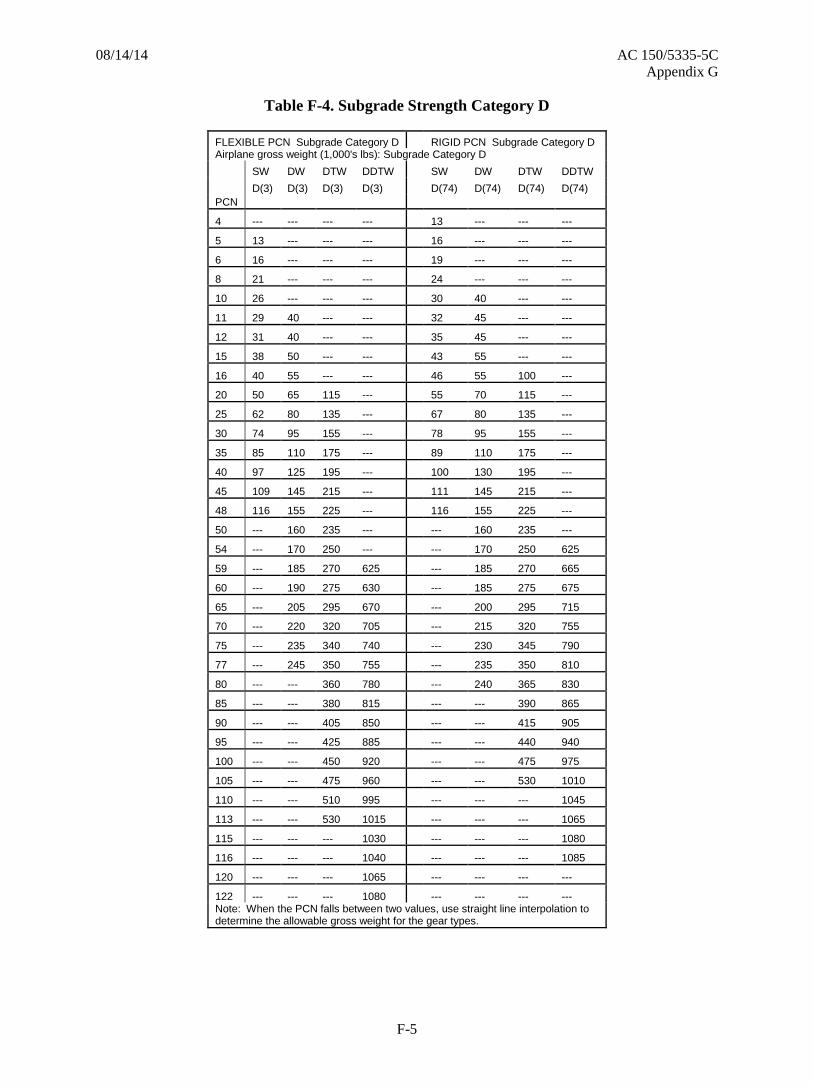
08/14/14 AC 150/5335-5C
Appendix G
F-5
Table F-4. Subgrade Strength Category D
FLEXIBLE PCN Subgrade Category D RIGID PCN Subgrade Category D Airplane gross weight (1,000's lbs): Subgrade Category D
SW DW DTW DDTW SW DW DTW DDTW
D(3) D(3) D(3) D(3) D(74) D(74) D(74) D(74)
PCN
4 --- --- --- --- 13 --- --- ---
5 13 --- --- --- 16 --- --- ---
6 16 --- --- --- 19 --- --- ---
8 21 --- --- --- 24 --- --- ---
10 26 --- --- --- 30 40 --- ---
11 29 40 --- --- 32 45 --- ---
12 31 40 --- --- 35 45 --- ---
15 38 50 --- --- 43 55 --- ---
16 40 55 --- --- 46 55 100 ---
20 50 65 115 --- 55 70 115 ---
25 62 80 135 --- 67 80 135 ---
30 74 95 155 --- 78 95 155 ---
35 85 110 175 --- 89 110 175 ---
40 97 125 195 --- 100 130 195 ---
45 109 145 215 --- 111 145 215 ---
48 116 155 225 --- 116 155 225 ---
50 --- 160 235 --- --- 160 235 ---
54 --- 170 250 --- --- 170 250 625
59 --- 185 270 625 --- 185 270 665
60 --- 190 275 630 --- 185 275 675
65 --- 205 295 670 --- 200 295 715
70 --- 220 320 705 --- 215 320 755
75 --- 235 340 740 --- 230 345 790
77 --- 245 350 755 --- 235 350 810
80 --- --- 360 780 --- 240 365 830
85 --- --- 380 815 --- --- 390 865
90 --- --- 405 850 --- --- 415 905
95 --- --- 425 885 --- --- 440 940
100 --- --- 450 920 --- --- 475 975
105 --- --- 475 960 --- --- 530 1010
110 --- --- 510 995 --- --- --- 1045
113 --- --- 530 1015 --- --- --- 1065
115 --- --- --- 1030 --- --- --- 1080
116 --- --- --- 1040 --- --- --- 1085
120 --- --- --- 1065 --- --- --- ---
122 --- --- --- 1080 --- --- --- --- Note: When the PCN falls between two values, use straight line interpolation to determine the allowable gross weight for the gear types.

08/14/14 AC 150/5335-5C
Appendix G
F-6
Page Intentionally Blank

08/14/14 AC 150/5335-5C
Appendix G
G-1
APPENDIX G. RELATED READING MATERIAL
The following publications were used during the development of this AC:
1. AC 150/5320-6, Airport Pavement Design and Evaluation. The FAA makes this
publication available for free on the FAA website at http://www.faa.gov.
2. ICAO Bulletin, Official Magazine of International Civil Aviation, Airport Technology,
Volume 35, No. 1, Montreal, Quebec, Canada H3A 2R2, January 1980.