Embed Size (px)
Citation preview

U.S. Department of Transportation Federal Aviation Administration
Advisory Circular
Subject: Measurement and Maintenance of Skid-Resistant Airport Pavement Surfaces
Date: DRAFT Initiated by: AAS-100
AC No: 150/5320-12D
1 1. What is the purpose of this Advisory Circular (AC)? 2
This AC contains guidelines and procedures for pavement evaluation with friction measuring 3 equipment, and maintenance of high skid-resistant pavements. 4
2. Does this AC cancel any prior ACs? 5
This AC cancels AC 150/5320-12C, Measurement, Construction, and Maintenance of Skid-6 Resistant Airport Pavement Surfaces, dated March 18, 1997. 7
3. To whom does this AC apply? 8
The FAA recommends that guidelines and standards contained herein for applications involving 9 runway friction measurement and maintenance. 10
4. What are the principal changes in this AC? 11
a. The Neubert Aero Corp. (NAC) Dynamic Friction Tester has been added as an 12 approved Continuous Friction Measuring Equipment (CFME). 13
b. The Halliday Technologies RT3 has been added as an approved Continuous Friction 14 Measuring Equipment (CFME). 15
c. The Traction Watcher One (TWO) has been added as an approved CFME. 16
d. Guidance for the design and construction of skid-resistant pavements is now 17 contained in AC 150/5370-10, Standards for Specifying Construction of Airports. 18
e. Recommended texture measuring techniques have been revised. 19
f. Contact information for approved CFME has been updated. 20
5. How are metrics represented? 21
Throughout this AC, customary English units are used followed with “soft” (rounded) 22 conversion to metric units. The English units govern. 23
DRAFT 150/5320-12D 3/24/2016
6. How can I acquire this AC, other FAA publications, and related reading material? 24
You can view a list of all ACs at http://www.faa.gov/regulations_policies/advisory_circulars/. 25 You can view the Federal Aviation Regulations at 26 http://www.faa.gov/regulations_policies/faa_regulations/. 27
APPENDIX B contains a listing of documents containing supplemental material relating to the 28 subject. Information on ordering these documents is also provided. 29
7. How can I provide comments or suggestions for improvements to this AC? 30
You can provide comments or suggestions for improvements to this AC to: 31
Manager, Airport Engineering Division 32 Federal Aviation Administration 33 800 Independence Avenue, S.W. 34 Washington, DC 20591 35
36 37 38 39 Michael J. O’Donnell 40 Director of Airport Safety and Standards 41
42
43
ii


DRAFT 150/5320-12D 3/24/2016
Table of Contents 44
CHAPTER 1. OVERVIEW ..........................................................................................................1 45
CHAPTER 2. QUALITIES OF SKID-RESISTANT PAVEMENTS .......................................3 46
Section 1. Basic Design Considerations ................................................................................. 3 47
Section 2. Hot-Mix Asphalt (HMA) Pavement ..................................................................... 4 48
Section 3. Portland Cement Concrete (PCC) Pavement ..................................................... 4 49
CHAPTER 3. PAVEMENT EVALUATION ..............................................................................7 50
Section 1. Need for and Frequency of Evaluation ................................................................ 7 51
Section 2. CFME - General .................................................................................................... 8 52
Section 3. Conducting Friction Evaluations with CFME .................................................... 9 53
Section 4. Conducting Texture Depth Measurements ....................................................... 12 54
CHAPTER 4. MAINTAINING HIGH SKID-RESISTANCE .................................................17 55
Section 1. Maintenance Considerations .............................................................................. 17 56
Section 2. Methods for Removing Contaminants............................................................... 17 57
APPENDIX A. QUALIFICATION PROCESS FOR CFMe ...................................................21 58
APPENDIX B. RELATED READING MATERIAL ...............................................................23 59
APPENDIX C. PERFORMANCE SPECIFICATIONS FOR CFME ....................................27 60
APPENDIX D. FAA-APPROVED CFME ................................................................................31 61
APPENDIX E. TRAINING REQUIREMENTS OUTLINE FOR CFME .............................33 62 63
List of Figures 64
Figure 2-1. AGGREGATE SLURRY SEAL.................................................................................. 5 65 Figure 3-1. APPARATUS FOR MEASURING SURFACE MACROTEXTURE DEPTH (With 66
permission of ASTM copied from E 965 – 96 (2006) ) ........................................ 14 67 Figure 3-2. MEASUREMENT OF MACRO TEXTURE DEPTH USING ASTM E 965 – 96. .. 15 68 Figure 3-3. APPARATUS FOR MEASURING SURFACE MACROTEXTURE DEPTH ........ 16 69 70
List of Tables 71
Table 3-1. FRICTION SURVEY FREQUENCY ........................................................................... 8 72 Table 3-2. FRICTION LEVEL CLASSIFICATION FOR RUNWAY PAVEMENT SURFACES73
............................................................................................................................... 11 74 Table 4-1. RUBBER DEPOSIT REMOVAL FREQUENCY ...................................................... 17 75

3/24/2016 DRAFT 150/5320-12D
76
77
78
79
80
81
82
83
84
85
86
87
Intentionally left blank.88
i

3/24/2016 DRAFT 150/5320-12D
CHAPTER 1. OVERVIEW 89
1-1. PURPOSE. This AC provides guidelines for maintaining skid-resistant airport pavement 90 surfaces and for conducting evaluations and surveys of runway friction for pavement 91 maintenance purposes. It also contains performance specifications for friction measuring 92 equipment. Guidance on pavement friction measurement for aircraft operational purposes during 93 winter weather and performance standards for decelerometers are found in AC 150/5200-30, 94 Airport Winter Safety and Operations. 95
1-2. BACKGROUND. Since the advent of turbojet aircraft with their greater weight and high 96 landing speeds, braking performance on runway surfaces, particularly when wet, has become a 97 significant safety consideration. A number of research programs sponsored by FAA, NASA, and 98 USAF, as well as those performed by foreign governments, have been directed in two major 99 areas: original pavement surface design to maximize skid resistance with proper materials and 100 construction techniques; and effective evaluation and maintenance techniques to detect 101 deterioration of skid-resistance and to restore it to acceptable levels. 102
1-3. PAVEMENT DESIGN RESEARCH. Pavement grooving was the first major step in 103 achieving safer pavement surfaces for aircraft operations in wet weather conditions. These 104 studies were completed by NASA at the Langley Research Center, Langley, Virginia, in 1968. 105 The FAA, through its Technical Center in Atlantic City, New Jersey, directed a test program on 106 pavement surface treatments at the Naval Air Engineering Center, Lakehurst, New Jersey. The 107 study was completed in 1983. Both the NASA Langley and the FAA Technical Center studies 108 showed that a high level of friction could be achieved on wet pavement by forming or cutting 109 closely spaced transverse grooves on the runway surface to allow rain water to escape from 110 beneath tires of landing aircraft. 111
In addition, a number of studies were carried out, and are continuing, on basic skid-resistant 112 behaviors of pavement surfaces, both HMA and Portland cement concrete (PCC). See AC 113 150/5370-10, Standards for Specifying Construction of Airports, for guidance on designing and 114 constructing skid-resistant pavements. 115
1-4. PAVEMENT MAINTENANCE AND EVALUATION RESEARCH. Regardless of 116 pavement type or surface treatment, runway friction characteristics will change over time, 117 depending on type and frequency of aircraft activity, weather, environmental effects, and other 118 factors. Pavements are subject to ordinary mechanical wear and tear from aircraft tires. In 119 addition, contaminants such as rubber deposits, dust particles, jet fuel, oil spillage, water, snow, 120 ice, and slush can collect on runway pavement surfaces and cause a decrease in friction. Rubber 121 is deposited in the touchdown areas on runways by the skidding of airplane tires spinning up on 122 landing. Such deposits can completely cover the pavement surface texture, causing loss of 123 aircraft braking capability and directional control when runways are wet. 124
In October 1978, the FAA embarked on a 2-year program to conduct friction and pavement 125 evaluation surveys at 268 airports (491 runways) within the contiguous United States. The 126 information obtained represented a very broad collection of data on the friction characteristics of 127 runways at airports that have turbojet aircraft operations. Field observations of the runway 128 pavement surface conditions and analysis of the friction test data identified those areas on the 129
1

DRAFT 150/5320-12D 3/24/2016
runway pavement which were below the minimum acceptable friction level. Test data and 130 surface condition information obtained during this program were given to airport owners so that 131 they could take proper corrective measures to eliminate runway pavement deficiencies. 132
1-5. FRICTION MEASURING EQUIPMENT RESEARCH. Beginning in the early 1970's, 133 NASA, FAA, and USAF conducted runway traction studies to determine the correlation between 134 various types of aircraft and friction measuring equipment. These studies showed a fair 135 correlation between some of the friction measuring devices, but the tests on correlation between 136 the friction devices and aircraft were inconclusive. The tests did show, however, that friction 137 measuring devices were effective when used to evaluate pavement surface friction properties for 138 maintenance purposes. 139
In March of 1990, FAA concluded a test program to evaluate the performance of different tires 140 on approved friction measuring devices and to develop correlation data in order to ensure that 141 devices of different manufacture and design would give comparable results in field use. 142 APPENDIX A summarizes research on qualification and correlation of friction measuring 143 equipment. 144
145
2

3/24/2016 DRAFT 150/5320-12D
CHAPTER 2. QUALITIES OF SKID-RESISTANT PAVEMENTS 146
Section 1. Basic Design Considerations 147
2-1. GENERAL. In building new runways, major reconstruction, or adding overlays, the 148 design engineer must choose either HMA or PCC as the basic paving component. The selection 149 is usually based on economics, local preference, and other design factors. These considerations, 150 as well as basic pavement structural design, are covered in AC 150/5320-6, Airport Pavement 151 Design and Evaluation. This AC is limited to discussion only of the surface of the airport 152 pavement, literally "where the rubber meets the runway." 153
2-2. SURFACE TEXTURE AND DRAINAGE. In discussing the effects of pavement texture 154 on friction and hydroplaning, two terms commonly used to describe the pavement surface are 155 micro-texture and macro-texture. Micro-texture refers to the fine scale roughness contributed by 156 small individual aggregate particles on pavement surfaces which are not readily discernible to 157 the eye but are apparent to the touch, i.e., the feel of fine sandpaper. Macro-texture refers to 158 visible roughness of the pavement surface as a whole. Micro-texture provides frictional 159 properties for aircraft operating at low speeds and macro-texture provides frictional properties 160 for aircraft operating at high speeds. Together they provide adequate frictional properties for 161 aircraft throughout their landing/takeoff speed ranges. 162
The primary function of macro-texture is to provide paths for water to escape from beneath the 163 aircraft tires. This drainage property becomes more important as the aircraft speed increases, tire 164 tread depth decreases, and water depth increases. All three of these factors contribute to 165 hydroplaning. Good micro-texture provides a degree of "sharpness" necessary for the tire to 166 break through the residual water film that remains after the bulk water has run off. Both 167 properties are essential in maintaining skid-resistant pavement surfaces. 168
Textural appearances, however, can be deceiving. A rough looking surface could provide 169 adequate drainage channels for the water to escape, but the fine aggregate in the pavement may 170 consist of rounded or uncrushed mineral grains that are subject to polishing by traffic, thereby 171 causing the pavement surface to become slippery when wet. Likewise, a less rough looking 172 surface, that may even have a shiny appearance when wet, will not necessarily be slippery if it 173 has good micro-textural properties. 174
All paving should, of course, be constructed with appropriate transverse slope for basic drainage 175 and must have adequate provision for prompt removal of storm runoff. AC 150/5300-13, Airport 176 Design, provides guidance in this area. 177
2-3. PAINTED AREAS ON PAVEMENT SURFACES. Painted areas of wet runway 178 pavement surfaces can be very slippery. In addition, an aircraft with one main gear on a painted 179 surface, and the other on an unpainted surface, may experience differential braking. It is 180 important to keep the skid-resistance properties of painted surfaces as close to that of unpainted 181 surfaces as possible. Usually this means adding a small amount of silica sand to the paint mix to 182 increase the friction properties of the painted surface. Glass beads, while used primarily to 183 increase conspicuity of markings, have been shown to increase friction levels, also. 184
3

DRAFT 150/5320-12D 3/24/2016
Section 2. Hot-Mix Asphalt (HMA) Pavement 185
2-4. CONSTRUCTION TECHNIQUES FOR HMA PAVEMENT. The construction 186 specification for HMA pavement is contained in AC 150/5370-10, Standards for Specifying 187 Construction of Airports. 188
2-5. CHIP SEAL. Recent advances in polymer technology have demonstrated the ability for 189 durable, long term improvement of runway surface friction through the use of polymer-based 190 chip seals. Sound engineering judgment should be exercised in the selection of a product when 191 considering the use of polymer-based chip seals for longer term improvements. This technology 192 has not been demonstrated to be compatible with grooved surfaces. A fog seal must be applied 193 on top of the chip seal to minimize loose chips and tire damage. Chips should have a maximum 194 size of 4.75mm (No. 4 sieve) to further minimize aircraft and tire damage. 195
2-6. AGGREGATE SLURRY SEAL. Temporary improvement of skid-resistance for 196 pavement surfaces can be gained by constructing an aggregate slurry seal, either gradation type 197 II or type III, as given in the specification in AC 150/5370-10. Aggregate slurry seals are 198 recommended only as an interim measure until an overlay is constructed. This type of 199 construction is usually adequate for 2 to 5 years. Figure 2-1 shows a typical type II aggregate 200 slurry seal. Experience has shown that slurry seals do not hold up well in cold climates where 201 snow removal occurs. A life cycle cost analysis should be conducted to determine the long term 202 benefits. 203
Section 3. Portland Cement Concrete (PCC) Pavement 204
2-7. CONSTRUCTION TECHNIQUES FOR PCC PAVEMENT. The basic construction 205 specifications for PCC pavement are given in AC 150/5370-10. Quality concrete is a prerequisite 206 to the retention of pavement skid-resistance. The physical properties of the fine aggregates and 207 effectiveness of curing are important factors in improving wear resistance. 208
2-8. SUITABILITY OF EXISTING PAVEMENTS FOR GROOVING. Existing pavements 209 may have surfaces that are not suitable for sawing grooves. A survey should be conducted to 210 determine if an overlay or rehabilitation of the pavement surface is required before grooving. 211
a. Reconnaissance. A thorough survey should be made of the entire width and length of the 212 runway. Bumps, depressed areas, bad or faulted joints, and badly cracked and/or spalled areas in 213 the pavement should not be grooved until such areas are adequately repaired or replaced. To 214 verify the structural condition of the pavement, tests should be taken in support of the visual 215 observations. 216
b. Tests. The strength and condition of the runway pavement should be evaluated and tested 217 according to the procedures specified in ACs 150/5320-6 and 150/5370-10. Future aircraft loads 218 and activity levels should be considered when making the evaluation. Core samples should be 219 taken in HMA pavement to determine stability. The American Society for Testing and Materials 220 (ASTM) Standard D 1559, Standard Test Method for Resistance to Plastic Flow of Bituminous 221 Mixtures Using Marshall Apparatus, provides methods for testing the resistance to plastic flow 222 of HMA pavements. Engineering judgment should be exercised when employing these methods 223 in determining the stability readings. These tests are recommended to be used for guidance only. 224
4

3/24/2016 DRAFT 150/5320-12D
Other factors should be considered in determining how long grooves will remain effective in 225 HMA pavements, such as maximum operational pavement surface temperature, effective tire 226 pressure, frequency of braking action in given areas, mix composition, and aggregate properties. 227 If, in the judgment of the person evaluating the existing pavement, any of the above conditions 228 are not met, the pavement should not be grooved. 229
2-9. OVERLAYS. If the evaluation shows that the existing pavement is not suitable, either 230 because of surface defects or from a strength standpoint, an overlay, flexible or rigid, will be 231 required. The new overlay may then be grooved according to the instructions given in the 232 following paragraphs: 233
2-10. PAVEMENT GROOVING. Construction specifications for grooving are given in AC 234 150/5370-10. 235
236
Figure 2-1. AGGREGATE SLURRY SEAL 237
5

DRAFT 150/5320-12D 3/24/2016
238
239
240
241
242
243
244
245
246
247
248
249
250
Intentionally left blank. 251
252
6

3/24/2016 DRAFT 150/5320-12D
CHAPTER 3. PAVEMENT EVALUATION 253
Section 1. Need for and Frequency of Evaluation 254
3-1. FRICTION DETERIORATION. Over time, the skid-resistance of runway pavement 255 deteriorates due to a number of factors, the primary ones being mechanical wear and polishing 256 action from aircraft tires rolling or braking on the pavement, and the accumulation of 257 contaminants, chiefly rubber, on the pavement surface. The effect of these two factors is directly 258 dependent upon the volume and type of aircraft traffic. Other influences on the rate of 259 deterioration are local weather conditions, the type of pavement (HMA or PCC), the materials 260 used in original construction, any subsequent surface treatment, and airport maintenance 261 practices. 262
Structural pavement failure such as rutting, raveling, cracking, joint failure, settling, or other 263 indicators of distressed pavement can also contribute to runway friction losses. Prompt repair of 264 these problems should be undertaken as appropriate. Guidance on corrective action may be found 265 in CHAPTER 2 and AC 150/5380-6. 266
Contaminants, such as rubber deposits, dust particles, jet fuel, oil spillage, water, snow, ice, and 267 slush, all cause friction loss on runway pavement surfaces. Removal and runway treatment for 268 snow, ice, and slush are covered in AC 150/5200-30. The most persistent contaminant problem is 269 deposit of rubber from tires of landing jet aircraft. Rubber deposits occur at the touchdown areas 270 on runways and can be quite extensive. Heavy rubber deposits can completely cover the 271 pavement surface texture causing loss of aircraft braking capability and directional control, 272 particularly when runways are wet. 273
3-2. SCHEDULING PAVEMENT EVALUATIONS. The operator of any airport with 274 significant jet aircraft traffic should schedule periodic friction evaluations of each runway that 275 accommodates jet aircraft. These evaluations should be carried out in accordance with the 276 procedures outlined in either CHAPTER 3. Section 2 or Section 3 of this chapter, depending 277 upon the availability to the airport operator of CFME. Every runway for jet aircraft should be 278 evaluated at least once each year. Depending on the volume and type (weight) of traffic on the 279 runways, evaluations will be needed more frequently, with the most heavily used runways 280 needing evaluation as often as weekly, as rubber deposits build up. Runway friction 281 measurements take time, and while tests are being conducted, the runway will be unusable by 282 aircraft. Since this testing is not time critical, a period should be selected which minimizes 283 disruption of air traffic. Airport operations management should work closely with air traffic 284 control, fixed base operators, and/or airlines. 285
3-3. MINIMUM FRICTION SURVEY FREQUENCY. Table 3-1 should be used as guidance 286 for the initial scheduling of runway friction surveys. This table is based on an average mix of 287 turbojet aircraft operating on any particular runway. Most aircraft landing on the runway are 288 narrow body, such as the DC-9, BAC-111, B-727, B-737, etc. A few wide body aircraft were 289 included in the mix. When any runway end has 20 percent or more wide body aircraft (L-1011, 290 B-747, DC- 10, MD-11, C-5, etc.) of the total aircraft mix, it is recommended that the airport 291 operator should select the next higher level of aircraft operations in Table 3-1 to determine the 292 minimum survey frequency. As airport operators accumulate data on the rate of change of 293
7

DRAFT 150/5320-12D 3/24/2016
runway friction under various traffic conditions, the scheduling of friction surveys should be 294 adjusted to a frequency that is adequate to ensure evaluators will detect and predict marginal 295 friction conditions in time to take corrective actions. 296
3-4. SURVEYS WITHOUT CFME. Research has shown that visual evaluations of pavement 297 friction are not reliable. An operator of an airport that does not support turbojet operations who 298 suspects that a runway may have inadequate friction characteristics should arrange for testing by 299 CFME. Visual inspections are essential, however, to note other surface condition inadequacies 300 such as drainage problems, including ponding and groove deterioration, and structural 301 deficiencies. 302
3-5. GROOVE DETERIORATION. Periodically, the airport operator should measure the 303 depth and width of a runway's grooves to check for wear and damage. When 40 percent of the 304 grooves in the runway are equal to or less than 1/8 inch (3 mm) in depth and/or width for a 305 distance of 1,500 feet (457 m), the grooves’ effectiveness for preventing hydroplaning has been 306 considerably reduced. The airport operator should take immediate corrective action to reinstate 307 the 1/4 inch (6 mm) groove depth and/or width. 308
Table 3-1. FRICTION SURVEY FREQUENCY 309
NUMBER OF DAILY MINIMUM TURBOJET AIRCRAFT LANDINGS
PER RUNWAY END
MINIMUM FRICTION SURVEY
FREQUENCY LESS THAN 15 1 YEAR
16 TO 30 6 MONTHS 31 TO 90 3 MONTHS 91 TO 150 1 MONTH 151 TO 210 2 WEEKS
GREATER THAN 210 1 WEEK NOTE: Each runway end should be evaluated separately, e.g., Runway 18 and Runway 36. 310
3-6. MEASUREMENT OF PAVEMENT SURFACE TEXTURE. When a friction test 311 identifies a pavement surface with inadequate friction characteristics, the cause, such as rubber 312 accumulation, is often obvious. When the cause is not obvious, the following guidance may be 313 helpful in determining if the deficiency is a result of deterioration in surface texture depth. Such 314 deterioration may be caused by weather influences, wear/polishing effects of aircraft traffic, and 315 contaminants including but not limited to rubber deposits. Visual inspections cannot be relied 316 upon to identify pavement surfaces with poor texture. Pavement texture depths can only be 317 determined by direct measurements. Even direct measurements may be affected by the operator 318 of the equipment, so they should be used as only part of an overall pavement friction evaluation. 319
Section 2. CFME - General 320
3-7. GENERAL REQUIREMENTS FOR CFME. All airports with turbojet traffic should own 321 or have access to CFME. Not only is it an effective tool for scheduling runway maintenance, it 322 can also be used in winter weather to enhance operational safety (see AC 150/5200-30). Airports 323
8

3/24/2016 DRAFT 150/5320-12D
that have few turbojet traffic operations may be able to borrow the CFME from nearby airports 324 for maintenance use, share ownership with a pool of neighboring airports, or hire a qualified 325 contractor. 326
3-8. FAA PERFORMANCE STANDARDS FOR CFME. APPENDIX C contains the 327 performance specifications for CFME. These standards should be used by airport operators in 328 procuring CFME and replacement tires for the equipment. 329
3-9. FAA QUALIFIED PRODUCT LIST. The equipment listed in APPENDIX D has been 330 tested and meets the FAA standards for CFME for use in conducting maintenance friction tests. 331
3-10. USE OF DECELEROMETER. Since decelerometers are not capable of providing 332 continuous friction measurements, and do not give reliable results on wet pavement surfaces, 333 they are not approved for conducting runway maintenance surveys as discussed in this AC. 334 However, the devices are approved for conducting friction surveys on runways during winter 335 operations (reference AC 150/5200-30). 336
3-11. FEDERAL FUNDING OF CFME. The Airport and Airway Improvement Act of 1982 337 (AAIA) includes friction measuring equipment as an eligible item for airport development. 338 However, before programming or procuring this equipment, airport operators should contact 339 their FAA Airports Regional or District Office for guidance. 340
3-12. TRAINING OF PERSONNEL. The success of friction measurement in delivering 341 reliable friction data depends heavily on the personnel who are responsible for operating the 342 equipment. Adequate professional training on the operation, maintenance, and procedures for 343 conducting friction measurement should be provided either as part of the procurement package 344 or as a separate contract with the manufacturer. Also, recurrent training is necessary for review 345 and update to ensure that the operator maintains a high level of proficiency. Experience has 346 shown that unless this is done, personnel lose touch with new developments on equipment 347 calibration, maintenance, and operating techniques. A suggested training outline for the 348 manufacturers is given in APPENDIX E. Airport personnel should be trained not only in the 349 operation and maintenance of the CFME but also on the procedures for conducting friction 350 surveys. These procedures are provided in Section 3 below. At airports where friction tests are 351 performed less frequently than quarterly, and CFME is not used for winter operations, 352 consideration should be given to hiring a qualified contractor to perform tests. 353
3-13. CALIBRATION. All CFME should be checked for calibration within tolerances given by 354 the manufacturer before conducting friction surveys. CFME furnished with self-wetting systems 355 should be calibrated periodically to ensure that the water flow rate and distribution is correct for 356 all test speeds. 357
Section 3. Conducting Friction Evaluations with CFME 358
3-14. PRELIMINARY STEPS. Friction measurement operations should be preceded by a 359 thorough visual inspection of the pavement to identify deficiencies as outlined in paragraphs 3-1 360 and 3-4. Careful and complete notes should be taken not only of the CFME data but of the visual 361 inspection as well. The airport operator should ensure that appropriate communications 362 equipment and frequencies are provided on all vehicles used in conducting friction surveys and 363
9

DRAFT 150/5320-12D 3/24/2016
that all personnel are fully cognizant of airport safety procedures. Personnel operating the 364 equipment should be fully trained and current in all procedures. The CFME should be checked 365 for accurate calibration and the vehicle checked for adequate braking ability. 366
3-15. LOCATION OF FRICTION SURVEYS ON THE RUNWAY. The airport operator, 367 when conducting friction surveys on runways at 40 mph (65 km/h), should begin recording the 368 data 500 feet (150 m) from the threshold end to allow for adequate acceleration distance. The 369 friction survey should be terminated approximately 500 feet (150 m) from the opposite end of 370 the runway to allow for adequate distance to safely decelerate the vehicle. When conducting 371 friction surveys at 60 mph (95 km/h), the airport operator should start recording the survey 1,000 372 feet (300 km) from the threshold end and terminate the survey approximately 1,000 feet (300 373 km) from the opposite end of the runway. Where travel beyond the end of the runway could 374 result in equipment damage or personal injury, additional runway length should be allowed for 375 stopping. Unless surface conditions are noticeably different on either side of the runway 376 centerline, a test on one side of the centerline in the same direction the aircraft lands should be 377 sufficient. However, friction surveys should be conducted in both directions, as rubber deposits 378 often result in different friction values based on direction. 379
The lateral location on the runway for performing friction surveys is based on the type and/or 380 mix of aircraft operating on the runway: 381
a. Runways Serving Only Narrow Body Aircraft. Friction surveys should be conducted 10 382 feet (3 m) to the right of the runway centerline. 383
b. Runways Serving Narrow Body and Wide Body Aircraft. Friction surveys should be 384 conducted 10 and 20 feet (3 and 6 m) to the right of the runway centerline to determine the worst 385 case condition. If the worst case condition is found to be consistently limited to one track, future 386 surveys may be limited to this track. Care should be exercised, however, to account for any 387 future and/or seasonal changes in aircraft mix. 388
3-16. VEHICLE SPEED FOR CONDUCTING SURVEYS. All of the approved CFME in 389 APPENDIX E can be used at either 40 mph (65 km/h) or 60 mph (95 km/h). The lower speed 390 provides an indication of the overall microtexture/contaminant/drainage condition of the 391 pavement surface. The higher speed provides an indication of the condition of the surface's 392 macrotexture. A complete survey should include tests at both speeds. 393
3-17. USE OF CFME SELF-WETTING SYSTEM. Since wet pavement always yields the 394 lowest friction measurements, CFME should routinely be used on wet pavement which gives the 395 "worst case" condition. CFME is equipped with a self-wetting system to simulate rain-induced 396 wet pavement surface conditions and provide the operator with a continuous record of friction 397 values along the length of the runway. The attached nozzle(s) are designed to provide a uniform 398 water depth of 1 mm (0.04 inch) in front of the friction measuring tire(s). This wetted surface 399 produces friction values that are most meaningful in determining whether or not corrective action 400 is required. 401
3-18. FRICTION SURVEYS DURING RAINFALL. One limitation in using the self-wetting 402 system on a friction measuring device is that it cannot by itself indicate the potential for 403
10

3/24/2016 DRAFT 150/5320-12D
hydroplaning. Some runways have depressed areas that pond during periods of moderate to 404 heavy rainfall. These areas may exceed considerably the water depth used by the self-wetting 405 system of the friction measuring device. Therefore, the airport operator should periodically 406 conduct visual checks of the runway surface during rainfall, noting the location, average water 407 depth, and approximate dimensions of the ponded areas. If the average water depth exceeds 1/8 408 inch (3 mm) over a longitudinal distance of 500 feet (150 m), the depressed area should be 409 corrected to the standard transverse slope. If possible, the airport operator should conduct 410 periodic friction surveys during rainfall through the ponded areas. 411
3-19. FRICTION LEVEL CLASSIFICATION. In physics, friction is defined as the ratio of the 412 force moving a surface parallel to another surface to the force perpendicular to those surfaces. It 413 is represented by the Greek letter μ (pronounced “myew,” and spelled “Mu” in English). Since 414 friction is dependent on both surfaces, it is incorrect to refer to a pavement’s friction value 415 without stating the method (device) by which the value is obtained. Mu values measured by 416 CFME can be used as guidelines for evaluating the surface friction deterioration of runway 417 pavements and for identifying appropriate corrective actions required for safe aircraft operations. 418 Table 3-2 depicts the friction values for three classification levels for FAA qualified CFME 419 operated at 40 and 60 mph (65 and 95 km/h) test speeds. This table was developed from 420 qualification and correlation tests conducted at NASA’s Wallops Flight Facility. 421
Table 3-2. FRICTION LEVEL CLASSIFICATION FOR RUNWAY PAVEMENT 422 SURFACES 423
40 mph (65 km/h) 60 mph (95 km/h)
Mini-mum
Maint-enance
Planning Mini-
mum
Maint-enance
Planning
Airport Surface Friction Tester .50 .60 .34 .47 Airport Technology USA Safegate Friction Tester .50 .60 .34 .47
Dynatest Consulting, Inc. Dynatest Runway Friction Tester .50 .60 .41 .54
Findlay, Irvine, Ltd. Griptester Friction Meter .43 .53 .24 .36
Halliday Technologies RT3 .45 .55 .42 .52
Moventor Oy Inc. BV-11 Skiddometer .50 .60 .34 .47
Mu Meter .42 .52 .26 .38
NAC Dynamic Friction Tester 42 52 28 38
Norsemeter RUNAR (operated at fixed 16% slip) .45 .52 .32 .42
Tatra Friction Tester .48 .57 .42 .52
11

DRAFT 150/5320-12D 3/24/2016
3-20. EVALUATION AND MAINTENANCE GUIDELINES. The following evaluation and 424 maintenance guidelines are recommended based on the friction levels classified in Table 3-2. 425 These guidelines take into account that poor friction conditions for short distances on the runway 426 do not pose a safety problem to aircraft, but long stretches of slippery pavement are of serious 427 concern and require prompt remedial action. 428
a. Friction Deterioration Below the Maintenance Planning Friction Level (500 ft, 150 m). 429 When the average Mu value on the wet runway pavement surface is less than the Maintenance 430 Planning Friction Level but above the Minimum Friction Level in Table 3-2 for a distance of 500 431 feet (150 m), and the adjacent 500 foot (150 m) segments are at or above the Maintenance 432 Planning Friction Level, no corrective action is required. These readings indicate that the 433 pavement friction is deteriorating but the situation is still within an acceptable overall condition. 434 The airport operator should monitor the situation closely by conducting periodic friction surveys 435 to establish the rate and extent of the friction deterioration. 436
b. Friction Deterioration Below the Maintenance Planning Friction Level (1000 ft, 300 m). 437 When the averaged Mu value on the wet runway pavement surface is less than the Maintenance 438 Planning Friction Level in Table 3-2 for a distance of 1000 feet (300 m) or more, the airport 439 operator should conduct extensive evaluation into the cause(s) and extent of the friction 440 deterioration and take appropriate corrective action. 441
c. Friction Deterioration Below the Minimum Friction Level. When the averaged Mu value 442 on the wet pavement surface is below the Minimum Friction Level in Table 3-2 for a distance of 443 500 feet (150 m), and the adjacent 500 foot (150 m) segments are below the Maintenance 444 Planning Friction Level, a NOTAM should be issued which states the runway is “Slippery when 445 wet” and corrective action should be taken immediately after determining the cause(s) of the 446 friction deterioration. Before undertaking corrective measures, the airport operator should 447 investigate the overall condition of the entire runway pavement surface to determine if other 448 deficiencies exist that may require additional corrective action. 449
Section 4. Conducting Texture Depth Measurements 450
3-21. RECOMMENDED TESTING. When friction values meet the criteria in paragraphs 3-451 20.a, 3-20.b, and 3-20.c, no texture depth measurements are necessary. When friction values do 452 not meet these criteria and the cause is not obvious (e.g. rubber deposits), the airport operator 453 should perform texture depth measurements. 454
3-22. RECOMMENDED TEXTURE DEPTHS. 455
a. Existing Pavements. For the purposes of texture evaluation, the runway is divided into 456 thirds lengthwise. 457
(1) When the average texture depth measurement in any third of the runway falls 458 below 0.045 inch (1.14 mm), the airport operator should conduct texture depth measurements 459 each time a runway friction survey is conducted. 460
12

3/24/2016 DRAFT 150/5320-12D
(2) When the average texture depth measurement in any third of the runway is below 461 0.030 inch (0.76 mm) but above 0.016 inch (0.40 mm), the airport operator should initiate plans 462 to correct the pavement texture deficiency within a year. 463
(3) When the average texture depth measurement in any third of the runway falls 464 below 0.010 inch (0.25 mm), the airport operator should correct the pavement texture deficiency 465 within 2 months. 466
b. Retexturing. Retexturing of the pavement surface should improve the average texture 467 depth to a minimum of 0.030 inch (0.76 mm). 468
3-23. LOCATION OF MEASUREMENTS. Groove depths are never included in texture depth 469 measurements. For grooved runway pavements, texture depth measurements should always be 470 located in non-grooved areas, such as near transverse joints or light fixtures, but as close as 471 possible to heavily trafficked areas. 472
3-24. TEST METHODS. A minimum of four texture depth measurements should be taken in 473 any area noted as deficient. More measurements should be taken when obvious textural changes 474 in the pavement surface are observed. An average texture depth should be computed for each 475 area. Three different macro-texture measurement methods are recommended for the 476 determination of commonly used macro-texture descriptors. Descriptions of these methods and 477 necessary equipment and the computations involved in determining texture depths are as follows: 478
3-25. TEST METHOD 1 - ASTM E 965 – 96, STANDARD TEST METHOD FOR 479 MEASURING PAVEMENT MACRO-TEXTURE DEPTH USING A VOLUMETRIC 480 TECHNIQUE. 481
a. Equipment. Another low-cost method is the standard macro-texture measurement test 482 method: ASTM E 965 – 96: Standard Test Method for Measuring Pavement Macro-texture 483 Depth Using a Volumetric Technique1 This method cannot be used to evaluate the pavement 484 micro-texture. The basic tools of the ASTM apparatus are depicted in Figure 3-. The minimal set 485 of tools contains the following material and equipment: 486
(1) Solid glass spheres (high quality sand). The gradation and quality requirements 487 are detailed in the ASTM D 1155 glass beads standard. 488
(2) A suitable container of a precise volume of 1.5 cubic in. (25 000 mm3). 489
(3) A flat, hard cylindrical shaped hard rubber disc approximately 1 in. (25 mm) thick 490 and 2.5 to 3.0 in. (60 to 75 mm) in diameter. (An ice hockey puck is considered suitable.) 491
(4) A stiff wire brush and a soft bristle brush. 492
1 This test method is under the jurisdiction of ASTM Committee E17 on Vehicle-Pavement Systems and is the direct responsibility of Subcommittee E17.23 on Surface Characteristics Related to Tire–Pavement Slip Resistance. Current edition approved Aug. 1, 2006. Published August 2006. Originally approved in 1983. Last previous edition approved in 2001 as E 965 – 96 (2001).
13

DRAFT 150/5320-12D 3/24/2016
(5) A suitable wind protection device. 493
b. Measurement. The following is a brief description of the procedures. The detailed 494 description of the measurements is given in the ASTM standard. A dry and relatively 495 homogeneous surface area with no surface discontinuities of distress (crack, joint etc.) is cleaned. 496 If necessary, the wind screening device is put around the selected surface area. The known 497 volume container is filled with the glass sand and poured onto the surface, preferably in small 498 cone shaped pile. The sand is spread into a circular patch with the disk tool. The diameter of the 499 sand-patch is measured at four equally spaced locations around the circumference. The average 500 of the measured diameters gives the patch diameter that is used to compute the macro-texture 501 depth using the formula given in paragraph 3-25.c. 502
503
Figure 3-1. APPARATUS FOR MEASURING SURFACE MACRO-TEXTURE DEPTH 504 (With permission of ASTM copied from E 965 – 96 (2006)) 505
c. Computation. After the area is completed, the following equations are used to calculate 506 the average texture depth of the pavement surface: 507
Average Texture Dept = 4 × Volume of Glass Sand
π × Diameter2
The same operator should perform the four measurements. The average of the four individual 508 macro-texture depth values is the average macro-texture depth of the tested pavement 509 surface. A measurement taken according to ASTM E 965 – 96 standard is depicted in Figure 510 3-. 511
14

3/24/2016 DRAFT 150/5320-12D
512
Figure 3-2. MEASUREMENT OF MACRO TEXTURE DEPTH USING ASTM E 965 – 96. 513
3-26. TEST METHOD 2 - ASTM E 2157 – 01 (2005), STANDARD TEST METHOD FOR 514 MEASURING PAVEMENT MACRO-TEXTURE PROPERTIES USING THE CIRCULAR 515 TRACK METER. 516
a. Equipment. A high-technology method is the standard macro-texture measurement test 517 method: ASTM E 2157 – 01 (2005): Standard Test Method for Measuring Pavement 518 Macrotexture Properties Using the Circular Track Meter.2 This method cannot be used to 519 evaluate the pavement micro-texture. The basic tools of the ASTM apparatus are depicted in 520 Figure 3-. The minimal set of tools contains the following material and equipment: 521
1. The Circular Track Texture Meter (CTM) measurement equipment. 522
2. Notebook computer for control and data storage and analyses. 523
3. A DC Power supply providing a minimum of 24W power at 12V-DC. 524
2 This test method is under the jurisdiction of ASTM Committee E17 on Vehicle-Pavement Systems and is the direct responsibility of Subcommittee E17.23 on Surface Characteristics Related to Tire Pavement Slip Resistance. Current edition approved Oct. 1, 2005. Published December 2005. Originally approved in 2001. Last previous edition approved in 2001 as E 2157 – 01.
15

DRAFT 150/5320-12D 3/24/2016
b. Measurement. The following is a brief description of the procedures. The detailed 525 description of the measurements is given in the ASTM standard. A flat, dry, and relatively 526 homogeneous surface area with no surface discontinuities of distress (crack, joint etc.) is cleaned. 527 The CTM is placed on the surface. Using the notebook computer connected to the CTM for 528 control, the mean profile depth (MPD) option is selected for texture depth computation. This 529 measurement is directly correlated to the sand-patch average texture depth measurements. The 530 four measurements are recorded and stored on the notebook computer. The average of the four 531 MPD measurements is the average Mean Predicted Texture Depth. 532
c. Computation. The following equations are used to calculate the average texture depth of 533 the pavement surface: 534
Average Texture Depth = 0.947 × MPD + 0.069
when Average Texture Depth and MPD are expressed in millimeters, 535
or: 536
Average Texture Depth = 0.947 × MPD + 0.0027
when Average Texture Depth and MPD are expressed in inches. 537
Figure 3-3. APPARATUS FOR MEASURING SURFACE MACRO-TEXTURE DEPTH 538
16

3/24/2016 DRAFT 150/5320-12D
CHAPTER 4. MAINTAINING HIGH SKID-RESISTANCE 539
Section 1. Maintenance Considerations 540
4-1. NEED FOR MAINTENANCE. As traffic wears down micro-texture and macro-texture, 541 and as contaminants build up on runway pavements, friction may decrease to a point where 542 safety is affected. At joint use airports where high numbers of military aircraft operations occur, 543 the venting of excess fuel can lead to serious loss of friction due to contaminants on the 544 pavement. Also, fog seal treatment of HMA surfaces can substantially reduce the pavement's 545 coefficient of friction during the first year after application. Surfaces which already have 546 marginally acceptable friction can become unacceptable when given this type of surface 547 treatment. 548
Table 4-1 may be used as an initial planning tool for budgeting for and scheduling timely 549 removal of rubber deposits and restoration of good friction characteristics. As stated in 550 CHAPTER 3, the average aircraft mix is based on mostly narrow body aircraft with a few wide 551 body aircraft operations included. Rubber accumulation is dependent on the type and frequency 552 of aircraft landing operations; e.g., weight of aircraft, the number of wheels that touchdown on 553 the surface, climate, runway length, and runway composition. When more than 20 percent of the 554 total aircraft mix landing on any one runway end are wide body aircraft, it is recommended that 555 the airport operator select the next higher level of aircraft operations in Table 4-1 to determine 556 the rubber removal frequency. Experience and the use of CFME will allow the airport operator to 557 develop a schedule specific to each runway. 558
Table 4-1. RUBBER DEPOSIT REMOVAL FREQUENCY 559
NUMBER OR DAILY TURBOJET AIRCRAFT LANDING PER RUNWAY END
SUGGESTED RUBBER DEPOSIT REMOVAL FREQUENCY
LESS THAN 15 2 YEARS 16 TO 30 1 YEAR 31 TO 90 6 MONTHS 91 TO 150 4 MONTHS 151 TO 210 3 MONTHS GREATER THAN 210 2 MONTHS
Section 2. Methods for Removing Contaminants 560
4-2. RECOMMENDED CONTAMINANT REMOVAL TECHNIQUES. Several methods are 561 available for cleaning rubber deposits, other contaminants, and paint markings from runway 562 surfaces. They include high pressure water, chemical, high velocity impact, and mechanical 563 grinding. After the contaminants have been removed from the runway surface by any of these 564 methods, the airport operator should conduct friction measurements to ensure the Mu values 565 have been restored to within 10 percent of those on the uncontaminated center portion of the 566 runway, and that both measurements are well within the acceptable friction levels for safe 567
17

DRAFT 150/5320-12D 3/24/2016
aircraft operations. The effectiveness of rubber deposit removal procedures cannot be evaluated 568 by visual inspection. It is highly recommended that rubber deposit removal contracts base 569 payments on final tests by CFME. A brief description follows for each of the contaminant 570 removal techniques. None of the techniques should be used unless the runway is free of standing 571 water, snow, slush, and/or ice. Also, chemical or water impact removal methods should not be 572 used if there is a danger of the fluids freezing. 573
The ultimate success of any method will depend on the expertise of the equipment operator. 574 Results can vary from completely ineffective to a situation where all rubber deposits are 575 removed, but the underlying pavement is significantly damaged. It is recommended that airport 576 operators require that a test section be cleaned by the contractor to demonstrate that rubber 577 deposits will be removed without damage to the underlying pavement. 578
a. Removal by High Pressure Water. A series of high pressure water jets is aimed at the 579 pavement to blast the contaminants from the surface, allowing the water to transport the rubber 580 particles to the edge of the runway. The technique is economical and removes deposits from the 581 pavement surface with minimal downtime to the airport operator. High-pressure water blasting 582 also may be used to improve the surface texture of smooth pavements. Water pressures used vary 583 significantly. There are so many other parameters that vary from one contractor's equipment to 584 another, however, that the pressure of the water used is not a good indication of the potential for 585 either effectiveness or pavement damage. The airport operator should rely on the contractor's 586 experience, demonstrated expertise, and references. 587
b. Removal by Chemicals. Chemical solvents have been used successfully for removal of 588 contaminants on both PCC and HMA runways. Any chemicals used on runways must meet 589 federal, state, and local environmental requirements. For removal of rubber deposits on PCC 590 runways, chemicals that have a base of cresylic acid and a blend of benzene are used, with a 591 synthetic detergent for a wetting agent. For removal of rubber deposits on HMA runways, 592 alkaline chemicals are generally used. Because of the volatile and toxic nature of such chemicals, 593 extreme care must be exercised during and after application. If the chemicals remain on the 594 pavement too long, the painted areas on the runway, and possibly the surface itself, could be 595 damaged. It is also very important to dilute the chemical solvent that is washed off the pavement 596 surface so that the effluent will not harm surrounding vegetation or drainage systems, or pollute 597 nearby streams and wildlife habitats. Detergents made of metasilicate and resin soap can be used 598 effectively to remove oil and grease from PCC runway surfaces. For HMA pavements, an 599 absorbent or blotting material such as sawdust or sand combined with a rubber alkaline degreaser 600 may be used. 601
c. High Velocity Impact Removal. This method employs the principle of throwing abrasive 602 particles at a very high velocity at the runway pavement surface, thus blasting the contaminants 603 from the surface. Additionally, the machine that performs this operation can be adjusted to 604 produce the desired surface texture, if so required. The abrasive is propelled mechanically from 605 the peripheral tips of radial blades in a high speed, fan like wheel. The entire operation is 606 environmentally clean in that it is self-contained; it collects the abrasive particles, loose 607 contaminants, and dust from the runway surface; it separates and removes the contaminants and 608 dust from the abrasive; and it recycles the abrasive particles for repetitive use. The machine is 609 very mobile and can be removed rapidly from the runway if required by aircraft operations. 610
18

3/24/2016 DRAFT 150/5320-12D
d. Mechanical Removal. Mechanical grinding that employs the corrugating technique has 611 been successfully used to remove heavy rubber deposits from both PCC and HMA runways. It 612 has also been used to remove high areas such as bumps on pavement surfaces or at joints where 613 slabs have shifted or faulted. This method greatly improves the pavement surface friction 614 characteristics. Pavement surfaces that are either contaminated (rubber buildup or bleeding) or 615 worn can have their surface friction coefficient greatly increased by a thin milling operation. 616 This technique removes a surface layer between 1/8 and 3/16 inch (3.2 and 4.8 mm) in depth 617
618
19

DRAFT 150/5320-12D 3/24/2016
619
620
621
622
623
624
625
626
627
628
629
630
631
Intentionally left blank. 632
.633
20

DRAFT AC 150/5320-12D Appendix A
APPENDIX A. QUALIFICATION PROCESS FOR CFME 634
A-1. FRICTION EQUIPMENT CORRELATION PROGRAM. From 1982 through 1985, the 635 FAA conducted a series of tests to determine the correlation of the Mu Meter, Saab Friction 636 Tester, Skiddometer, and the Runway Friction Tester, using equipment-provided self-wetting 637 systems on dry pavement surfaces at NASA's Wallops Flight Facility. Correlation values were 638 established for each device. Reference Report No. DOT/FAA/AS-90-1, which shows the results 639 of the correlation trials conducted at NASA’s Wallops Flight Facility in August 1989. As trials at 640 Wallops ceased in 2008, research continued on performance based requirements at the Annual 641 Friction Workshop at Penn States’ Larson Institute and University Park Airport. Additional 642 devices that have since been found to meet FAA specifications. All devices found to meet FAA 643 specifications as of the date of this AC are listed in APPENDIX D. 644
A-2. FRICTION/SPEED RELATIONSHIPS FOR PAVEMENT SURFACES. The 645 relationship of speed to friction has a profound influence on aircraft braking performance when 646 pavements have little or no microtextural properties. According to the Unified Mechanism of 647 Rubber/Pavement Friction, the adhesion component of friction, which is governed mainly by the 648 shear force between the tire and the pavement surface, is high at lower speeds of up to about 100 649 mph (165 km/h). The rubber couples well with a good micro-textured surface to provide high 650 friction at the lower speeds. At speeds over 100 mph (165 km/h), the hysteresis component of 651 friction governs. This component is the effect of damping or reacting elastic pressure of rubber 652 when deformed around aggregate particles. The deformation is produced best by good macro-653 textured surfaces. In essence, the Unified Mechanism simply states that a good macro/micro-654 texture surface will provide relatively high friction and flat friction speed gradient on wet 655 pavement surfaces. As speed increases, macro-textured surfaces will provide good drainage to 656 keep the hydrodynamic pressure low and the tire in contact with the pavement surface for a low 657 friction/speed gradient. However, a poor macro-textured pavement surface cannot provide 658 sufficient drainage for good tire/pavement contact. Thus, the friction speed gradient decreases 659 rapidly. 660
The relationship of the friction/speed gradient was determined at NASA's Wallops Flight Facility 661 by conducting friction surveys on several types of pavement surfaces that represented a wide 662 range of friction values at speeds of 20, 40, 60, and 80 mph (33, 65, 95, and 133 km/h). Testing 663 operational runways at 20 mph is not practicable, since a test of a 10,000' runway would take 664 approximately six minutes. Likewise, the distance required to accelerate to and decelerate from 665 80 mph would preclude testing most of a typical touchdown zone. Therefore, a compromise is 666 made and tests are conducted at only two speeds, 40 and 60 mph (65 and 95 km/h). These two 667 speeds will provide an adequate representation of the friction/speed gradient for the various 668 textured pavement surfaces encountered. 669
A-3. DEVELOPMENT OF PERFORMANCE SPECIFICATION FOR FRICTION 670 EQUIPMENT. The following paragraphs discuss the qualification process used to develop the 671 performance specification for the friction equipment and friction measuring tires. 672
a. Development of the Friction Equipment Performance Specification. For friction 673 measuring equipment to qualify for federal funding, performance standards are necessary. 674 Testing was conducted at NASA's Wallops Flight Facility to develop performance standards for 675
21

AC 150/5320-12D DRAFT Appendix A
friction measuring equipment. The standards were developed to assure the airport operator that 676 the friction measuring equipment would perform with reliability and consistency on all types of 677 pavement surface conditions. 678
b. Development of the Tire Performance Specification. Prior to 1989, only one friction 679 measuring tire was available for friction measuring devices. During 1988, the E-17 committee of 680 ASTM requested the FAA to conduct tire performance tests on two tires manufactured according 681 to two ASTM specifications — E-524, Specification for Standard Smooth Tire for Pavement 682 Skid-Resistance Tests; and E-670, Standard Test Method for Side Force Friction on Paved 683 Surfaces — and to use the Mu-Meter to compare these tires with the performance of the then 684 FAA standard tire. Test tire specifications were developed and adopted by ASTM as E1551, 685 Standard Specification for Special Purpose, Smooth–Tread Tire, Operated on Fixed Braking Slip 686 Continuous Friction Measuring Equipment and E1844 Standard Specification for A Size 10 & 4–687 5 Smooth-Tread Friction Test Tire. The tires are manufactured in the United States by: 688
Specialty Tires of America Inc. 689 1600 Washington Street 690
Indiana, PA 15701. 691
22

DRAFT AC 150/5320-12D Appendix B
APPENDIX B. RELATED READING MATERIAL 692
B-1. The latest issues of the following free publications may be obtained from the U.S. 693 Department of Transportation, Warehousing and Subsequent Distribution Section, SVC-121.23, 694 Washington, DC 20590. AC 00-2, Advisory Circular Checklist, current edition, contains the 695 listing of all current issues of circulars and changes thereto. 696
a. AC 150/5200-28, Notices to Airman (NOTAMS) for Airport Operators. 697
b. AC 150/5200-30, Airport Winter Safety and Operation. 698
c. AC 150/5320-6, Airport Pavement Design and Evaluation. 699
B-2. Copies of the following publications may be obtained from the Superintendent of 700 Documents, U.S. Government Printing Office, Washington, DC 20402. Send check or money 701 order with your request made payable to the Superintendent of Documents in the amount stated. 702 No C.O.D. orders are accepted. 703
a. AC 150/5300-13, Airport Design. 704
b. AC 150/5370-10, Standards for Specifying Construction of Airports, current edition 705 ($18.00). 706
c. AC 150/5380-6, Guidelines and Procedures for Maintenance of Airport Pavements 707 ($7.00). 708
B-3. Copies of ASTM Standards ‘Volume 04.03 Road and Paving Materials; Vehicle-709 Pavement Systems,’ may be obtained from the American Society For Testing and Materials, 100 710 Barr Harbor Drive; Conshohochen, PA 19428. 711
B-4. Copies of the following publications may be obtained from the National Technical 712 Information Service, Springfield, Virginia 22151. 713
a. Pavement Grooving and Traction Studies, Report No. NASA SP-5073, 1969. 714
b. A Comparison of Aircraft and Ground Vehicle Stopping Performance on Dry, Wet, 715 Flooded, Slush, and Ice-covered Runways, Report No. NASA TN D-6098, November 1970. 716
c. Runway Friction Data for 10 Civil Airports as Measured with a Mu Meter and 717 Diagonal Braked Vehicle, Report No. FAA-RD-72-61, July 1972. 718
d. Effects of Pavement Texture on Wet Runway Braking Performance, Report No. 719 NASA TN D-4323, January 1969. 720
e. Porous Friction Surface Courses, Report No. FAA-RD-73-197, February 1975. 721
f. Laboratory Method for Evaluating Effect of Runway Grooving on Aircraft Tires, 722 Report No. FAARD-74-12, March 1974. 723
23

AC 150/5320-12D DRAFT Appendix B
g. Investigation of the Effects of Runway Grooves on Wheel Spin-up and Tire 724 Degradation, Report No. FAA-RD-71-2, April 1971. 725
h. Environmental Effects on Airport Pavement Groove Patterns, Report No. FAA-RD-726 69-37, June 1969. 727
i. The Braking Performance of an Aircraft Tire on Grooved Portland Cement Concrete 728 Surfaces, Report No. FAA-RD-80-78, January 1981. 729
j. Braking of an Aircraft Tire on Grooved and Porous Asphaltic Concrete, Report No. 730 DOT-FAARD-82-77, January 1983. 731
k. Analytical and Experimental Study of Grooved Pavement Runoff, Report No. DOT-732 FAA-PM83/84, August 1983. 733
l. Surveys of Grooves in Nineteen Bituminous Runways, Report No. FAA-RD-79-28, 734 February 1979. 735
m. Modified Reflex-Percussive Grooves for Runways, Report No. DOT-FAA-PM-82-8, 736 March 1984. 737
n. Reliability and Performance of Friction Measuring Tires and Friction Equipment 738 Correlation, Report No. DOT/FAA/AS-90-1, March 1990. 739
B-5. Copies of MS-16, Asphalt in Pavement Maintenance, may be obtained from the Asphalt 740 Institute Building, College Park, Maryland 20740. 741
B-6. Copies of Maintenance Practices for Concrete Pavements, may be obtained from the 742 Portland Cement Association, Old Orchard Road, Skokie, Illinois 60076. 743
B-7. Copies of the following publications may be obtained from the Highway Research Board, 744 National Academy of Sciences, 2101 Constitution Avenue, Washington, D.C. 20418. 745
a. Skid-resistance, National Cooperative Highway Research Program (NCHRP) 746 Synthesis of Highway Practice 14, 1972. 747
b. Pavement Rehabilitation - Materials and Techniques, National Cooperative Highway 748 Research Program (NCHRP) Synthesis of Highway Practice 9, 1972. 749
c. Factors Affecting Skid-resistance and Safety of Concrete Pavements, Special Report 750 No. 101, 1969. 751
d. Road Surface Texture and the Slipperiness of Wet Roads, Record No. 214, 1968. 752
e. Pilot Field Study of Concrete Pavement Texturing Methods, Record No. 389, 1972. 753
f. Prediction of Skid-resistance Gradient and Drainage Characteristics of Pavements, 754 Record No. 131, 1966. 755
24

DRAFT AC 150/5320-12D Appendix B
g. Standard Nomenclature and Definitions for Pavement Components and Deficiencies, 756 Special Report No. 113, 1970. 757
h. Development of Specifications for Skid-Resistant Asphalt Concrete, Record No. 396, 758 1972. 759
i. Skid-resistance of Screenings for Seal Coats, Record No. 296, 1968. 760
B-8. Copies of the following technical bulletins may be purchased from the American 761 Concrete Paving Association, Suite 490, 3800 N. Wilke Rd., Arlington Heights, Illinois, 60004-762 1268. 763
a. Texturing of Concrete Pavements, Bulletin No. 1. 764
b. Interim Recommendations for the Construction of Skid-Resistant Concrete Pavement, 765 Bulletin No. 6. 766
c. Guideline for Texturing of Portland Cement Concrete Highway Pavements, Bulletin 767 No. 19. 768
B-9. Copies of Evaluation of Two Transport Aircraft and Several Ground Test Vehicle 769 Friction Measurements Obtained for Various Runway Surface Types and Conditions, NASA 770 Technical Paper 2917, February 1990, may be obtained from NASA, under the Code NTT-4, 771 Washington, DC 20546-0001. 772
B-10. Copies of ASTM Specifications can be obtained from ASTM, 1916 Race Street, 773 Philadelphia, Pennsylvania 19103. 774
775
25

AC 150/5320-12D DRAFT Appendix B
776
777
778
779
780
781
782
783
784
785
786
787
788
Intentionally left blank. 789
790
26
DRAFT AC 150/5320-12D Appendix C
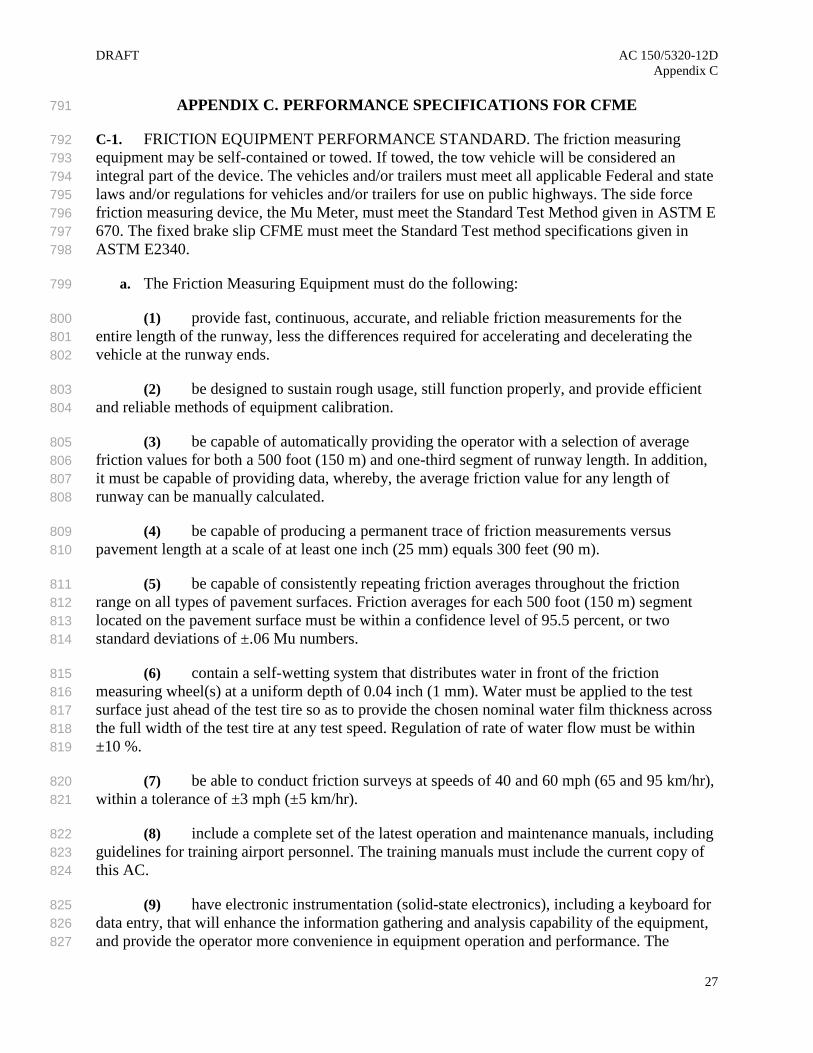
APPENDIX C. PERFORMANCE SPECIFICATIONS FOR CFME 791
C-1. FRICTION EQUIPMENT PERFORMANCE STANDARD. The friction measuring 792 equipment may be self-contained or towed. If towed, the tow vehicle will be considered an 793 integral part of the device. The vehicles and/or trailers must meet all applicable Federal and state 794 laws and/or regulations for vehicles and/or trailers for use on public highways. The side force 795 friction measuring device, the Mu Meter, must meet the Standard Test Method given in ASTM E 796 670. The fixed brake slip CFME must meet the Standard Test method specifications given in 797 ASTM E2340. 798
a. The Friction Measuring Equipment must do the following: 799
(1) provide fast, continuous, accurate, and reliable friction measurements for the 800 entire length of the runway, less the differences required for accelerating and decelerating the 801 vehicle at the runway ends. 802
(2) be designed to sustain rough usage, still function properly, and provide efficient 803 and reliable methods of equipment calibration. 804
(3) be capable of automatically providing the operator with a selection of average 805 friction values for both a 500 foot (150 m) and one-third segment of runway length. In addition, 806 it must be capable of providing data, whereby, the average friction value for any length of 807 runway can be manually calculated. 808
(4) be capable of producing a permanent trace of friction measurements versus 809 pavement length at a scale of at least one inch (25 mm) equals 300 feet (90 m). 810
(5) be capable of consistently repeating friction averages throughout the friction 811 range on all types of pavement surfaces. Friction averages for each 500 foot (150 m) segment 812 located on the pavement surface must be within a confidence level of 95.5 percent, or two 813 standard deviations of ±.06 Mu numbers. 814
(6) contain a self-wetting system that distributes water in front of the friction 815 measuring wheel(s) at a uniform depth of 0.04 inch (1 mm). Water must be applied to the test 816 surface just ahead of the test tire so as to provide the chosen nominal water film thickness across 817 the full width of the test tire at any test speed. Regulation of rate of water flow must be within 818 ±10 %. 819
(7) be able to conduct friction surveys at speeds of 40 and 60 mph (65 and 95 km/hr), 820 within a tolerance of ±3 mph (±5 km/hr). 821
(8) include a complete set of the latest operation and maintenance manuals, including 822 guidelines for training airport personnel. The training manuals must include the current copy of 823 this AC. 824
(9) have electronic instrumentation (solid-state electronics), including a keyboard for 825 data entry, that will enhance the information gathering and analysis capability of the equipment, 826 and provide the operator more convenience in equipment operation and performance. The 827
27

AC 150/5320-12D DRAFT Appendix C information gathered must be stored electronically for easy retrieval and be readily visible to the 828 operator of the vehicle. Each printout of the chart produced by the system electronics must 829 include the following recorded information: runway designation and date; time of friction 830 survey; a continuous trace of the friction values obtained for the entire runway length minus the 831 acceleration/deceleration distances; printed marks depicting each 100 foot (30 m) increment of 832 the runway length so easy reference can be made by the operator in identifying specific areas on 833 the runway pavement surface; average friction value for 500 foot (150 m) and one-third 834 segments of the runway length as preselected by the operator; and average vehicle speed for that 835 segment. 836
b. The vehicle must: 837
(1) be able to conduct friction surveys at speeds of 40 and 60 mph (65 and 95 km/hr), 838 within a tolerance of ±3 mph (±5 km/hr). The vehicle, when fully loaded with water, must be 839 capable of accelerating to these speeds within 500 and 1000 feet (150 and 300 m) from the 840 starting position, respectively. 841
(2) be equipped with electronic speed control. 842
(3) conform to the requirements of AC 150/5210-5, Painting, Marking, and Lighting 843 of Vehicles Used on an Airport, for airfield service vehicles. 844
(4) be equipped with transceiver(s) necessary for communication with airport 845 operations and air traffic control. 846
(5) be able to lock the test wheel for calibration purposes. The test wheel shall be 847 placed on a load plate with three dimensional load measurement capabilities (vertical and two 848 dimensions horizontally (longitudinal and transverse). The plate shall have precise levelling 849 capabilities and there shall be a non-slip coating where the test wheel comes in contact with the 850 plate. The load plate shall be calibrated by an ISO 17025 certified organization and tests 851 performed before the plate calibration expiration date. The test wheel shall be placed on the plate 852 and the its vertical forces be verified within 10% of the plate readings. With the wheel locked, 853 horizontal and transverse forces shall be placed on the load plate and the vehicle shall indicate a 854 reading within 10% with the associated readings on the load plate. 855
(6) be equipped with a water tank constructed of strong lightweight material, of 856 sufficient capacity to complete a friction survey on a 14,000 foot (4,300 m) runway in one 857 direction, and all necessary appurtenances to deliver the required water flow rate to the friction 858 measuring wheel(s). 859
(7) be equipped with appropriate heavy duty shock absorbers and heavy duty 860 suspension to adequately handle imposed loads. The test/tow vehicle must not exceed the vehicle 861 manufacturer’s given gross vehicle weights and tire loading specifications when fully loaded. 862
(8) be equipped with internally controlled spotlights on each side of the vehicle. For 863 trailer mounted equipment, the tow vehicle must also be equipped with at least two floodlights 864 mounted such that the friction measuring device and rear portion of the tow vehicle is 865 illuminated to a level of at least 20 foot-candles within an area bounded by lines 5 feet (2 m) on 866
28

DRAFT AC 150/5320-12D Appendix C
either side of the friction measuring device and 5 feet (2 m) in front of and behind the friction 867 measuring device. 868
(9) be equipped with an air conditioner when specified by the purchaser. 869
c. The manufacturer must perform a comparison of the Mu values obtained from its own 870 device to the Mu values obtained under the same conditions from another device in Table 3-2. 871 The manufacturer must use this comparison to determine the Mu value readings of its device that 872 are equivalent to the milestone values listed for the other devices. These values will be used to 873 update Table 3-2. 874
C-2. TIRE PERFORMANCE STANDARD. The friction measuring equipment must be 875 furnished with measuring tires which are designed for use in conducting friction surveys and 876 which meet ASTM standard E670, E-1551, or E-1844, as appropriate. Non-ribbed (smooth) 877 tire(s) must be used to eliminate the effect of tire tread wear and provide greater sensitivity to 878 variations in pavement surface texture. The tires must be furnished with split rims and the tubes 879 must have curved valve stems. The manufacturer of the friction equipment must provide the 880 airport user with a calibrated dial pressure gauge. 881
A new test tire must not be used until it has been conditioned by running at fixed slip at the 882 normal tire inflation pressure to obtain a smooth, uniform rubber tread surface free of any curing 883 agents. For tires not conditioned and tested by the supplier, conditioning may typically be carried 884 out by the operator running the tire dry for about 100 ft (30 m) followed by about 1000 ft (300 885 m) on a wet surface. The operator must be aware that these lengths are typical and, on an 886 aggressive surface, the tire need not be run dry for as much as 30 m and, on a smooth surface, 887 longer conditioning will be required. 888
29

AC 150/5320-12D DRAFT Appendix C 889
890
891
892
893
894
895
896
897
898
899
900
901
Intentionally left blank. 902
903
904
30

DRAFT AC 150/5320-12D Appendix D
APPENDIX D. FAA-APPROVED CFME 905
AIRPORT SURFACE FRICTION TESTER INDUSTRIES AB Piledalsv. 51 271 73 Kopingebro Sweden
AIRPORT SURFACE FRICTION TESTER +46 0 411 651 00 FAX +46 0 411 190 12 Web site: www.asft.se Email: [email protected]
AIRPORT TECHNOLOGY USA NO LONGER AVAILABLE
SAFEGATE FRICTION TESTER
DOUGLAS EQUIPMENT LTD Douglas House Village Road Cheltenham Gloucestershire GL51 0AB United Kingdom
MU METER + 44 (0)1242 527921 FAX +44 (0) 1242 571667 Web site: www.douglas-equipment.com Email: [email protected]
DYNATEST CONSULTING, INC., (FORMERLY K.J. LAW ENGINEERS, INC.) 38284 Abruzzi Drive Westland, MI 48185
RUNWAY FRICTION TESTER (6810, 6850 and 6875) (734) 729-0400 FAX (734) 729-0401 Web site: www.dynatest.com Email: [email protected]
FINDLAY, IRVINE, LTD. Bog Road Penicuik Midlothian EH26 9BU Scotland United Kingdom
GRIPTESTER FRICTION TESTER + 44 (0) 1968 671 200 FAX + 44 (0) 1968 671 237 Web site: www.findlayirvine.com Email: http://www.findlayirvine.com/contact-us
HALLIDAY TECHNOLOGIES 8525 Rausch Drive Plain City, OH 43064
RT3 (614) 504 4150 FAX (614) 873 3842 Web site: www.hallidaytech.com Email: [email protected]
INTERTECH ENGINEERING NO LONGER AVAILABLE
TATRA FRICTION TESTER
MOVENTOR OY INC. Viherkiitäjä 2 33960 Pirkkala Finland
BV-11 SKIDDOMETER tel. +358 (0)10 2896100 Web site: www.moventor.com Email: [email protected]
NEUBERT AERO CORP. 4105 West De Leon Street Tampa, FL 33609
NAC DYNAMIC FRICTION TESTER (727) 538-8744 FAX (727) 538-8765 Web site: www.airportnac.com Email: [email protected]
NORSEMETER P.O.Box 125, Bogstadveien N-0323 Oslo, Norway
RUNAR RUNWAY ANALYSER AND RECORDER +47 23 20 1270 FAX +47 23 20 1271 Web site: www.norsemeter.no Email: [email protected]
Olsense Technology AS Bergstigen 1C 1472 Fjellhamar Norway
Traction Watcher One (TWO) +47 480 28 460 Web site: www.two-friction.com Email: [email protected]
SCANDINAVIAN AIRPORT AND ROAD SYSTEMS AB) Box 31, Sjoviksvagen 4) SE 231 21 Trelleborg Sweden
SARSYS FRICTION TESTER (SFT) SARSYS TRAILER FRICTION TESTER (STFT) SARSYS SURFACE VOLVO FRICTION TESTER (SVFT -VOLVO V70, XC70, SKODA OCTOVIA) SARSYS SURFACE TRAILER (STFT) SARSYS SURFACE FRICTION TESTER
31

AC 150/5320-12D DRAFT Appendix D
US/Canada:. Tradewind Scientific Ltd. Box 3262, Station D Ottawa, Ontario, Canada K1P 6H8
TRANSPORTER (SFTT – VW TRANSPORTER, VW CARAVELLER, VW MULTIVAN) SARSYS SURFACE OPEL FRICTION TESTER (SOFT – OPEL MOKKA, VAUXHAL MOKKA, BUICK ENCORE, CHEVROLET TRAX, HOLDEN TRAX) +46 410 46 110 FAX +46 410 46 111 Web site: www.sarsys.se Email: [email protected] (613) 238-1246 FAX: (613) 726-0871 Web site: www.tradewind.aero E-mail:[email protected]
906
907
32

DRAFT AC 150/5320-12D Appendix E
APPENDIX E. TRAINING REQUIREMENTS OUTLINE FOR CFME 908
E-1. GENERAL DISCUSSION. The following paragraph lists the major items which should 909 be considered in developing a training program for airport personnel responsible for operating 910 and maintaining CFME. Whenever a major change in equipment design occurs, the training and 911 instruction manuals should be revised. A document titled Training and Instruction Manual 912 should always be provided to the airport personnel by the manufacturer and kept updated. 913
E-2. TRAINING REQUIREMENTS OUTLINE. 914
a. Classroom Instruction. 915
(1) Purpose of Training Program. 916
(2) General Discussion on Pertinent Federal Aviation Regulations. 917
(3) General Discussion on Pertinent ACs. 918
(4) General Discussion on Pertinent ASTM Standards. 919
(5) General Overview of Program. 920
(6) Review of Requirements in AC 150/5320-12. 921
(a) Coefficient of Friction Definition. 922
(b) Factors Affecting Friction Conditions. 923
(c) ASTM Standards for CFME. 924
(d) Programming the Computer for FAA and ICAO Formats. 925
(e) Maintenance of CFME. 926
(f) Procedures for Reporting Friction Numbers. 927
(g) Preparation and Dissemination of NOTAMS. 928
(7) Orientation to the Calibration, Operation, and Maintenance of CFME. 929
b. Field Experience. Operation and Maintenance of CFME. 930
c. Testing. Solo Test and Written Examination on All Items Covered in Course. 931
d. Award of Training Certificate. 932
33

AC 150/5320-12D DRAFT Appendix E
933
934
935
936
937
938
939
940
941
942
943
944
945
Intentionally left blank. 946
947
34