Embed Size (px)
Citation preview

ADWSN: ADRadioNet
Technology Guide
ADWSN: ADRadioNet-v1.1TG IISET-TG-ADRadioNet-v1.1, August 14, 2014

Copyright, Disclaimer & Trademark Statements
Copyright Information
Copyright (c) 2014 Analog Devices, Inc. All Rights Reserved. This software is
proprietary and confidential to Analog Devices, Inc. and its licensors. This document
may not be reproduced in any form without prior, express written consent from Analog
Devices, Inc.
Disclaimer
Analog Devices, Inc. reserves the right to change this product without prior notice.
Information furnished by Analog Devices is believed to be accurate and reliable.
However, no responsibility is assumed by Analog Devices for its use; nor for any
infringement of patents or other rights of third parties which may result from its use.
No license is granted by implication or otherwise under the patent rights of Analog
Devices, Inc.
ADWSN ADRadioNet Technology Guide Page 3
Contents
Introduction ......................................................................................................................................................... 6
Overview of WSN ........................................................................................................................................... 6
Components of WSN ................................................................................................................................... 7
Sub-GHz Wireless Systems ............................................................................................................................. 7
Standard vs. Proprietary solutions ................................................................................................................... 8
Why Proprietary WSN? ................................................................................................................................... 8
What is ADRadioNet? ......................................................................................................................................... 9
Protocol Overview ........................................................................................................................................... 9
Features of ADRadioNet ................................................................................................................................. 9
Basic Concepts & Terminology .................................................................................................................... 10
Concept of Orbits ...................................................................................................................................... 10
Upstream and Downstream ....................................................................................................................... 11
Star, Multi Star, Mesh ............................................................................................................................... 11
Multi Channel ............................................................................................................................................ 11
Address Binding ........................................................................................................................................ 12
Message Components .................................................................................................................................... 12
UART Message Format ............................................................................................................................. 12
Physical Layer Packet Components .......................................................................................................... 12
Packet format at MAC layer ...................................................................................................................... 12
Sending OTA Commands .......................................................................................................................... 14
Routing and Addressing ................................................................................................................................ 15
Routing ...................................................................................................................................................... 15
Addressing ................................................................................................................................................. 15
Elucidating Configuration Settings ............................................................................................................... 17
Basic Configuration Parameters: ............................................................................................................... 17
PHY Parameters: ....................................................................................................................................... 19
Protocol Parameters: .................................................................................................................................. 19
Device Description: ................................................................................................................................... 19

ADWSN ADRadioNet Technology Guide Page 4
Network Formation ....................................................................................................................................... 20
Joining the Network .................................................................................................................................. 20
Lost Network ............................................................................................................................................. 20
Departing the Network .............................................................................................................................. 20
Application Programming Interface .................................................................................................................. 21
API’s Explained ............................................................................................................................................ 21
API_SET_1: Configuration & Initialization .............................................................................................. 21
API_SET_2: Protocol State Machine ........................................................................................................ 25
API_SET_3: Data Communication – Sending & Receiving data. ............................................................ 27
API_SET_4: Low power Operation. ......................................................................................................... 29
API_SET_5: PC tool interface & control .................................................................................................. 31
Deep Dive into ADRadioNet ............................................................................................................................. 34
Main State Machine ....................................................................................................................................... 34
Mode Control ................................................................................................................................................ 34
ModeControl.............................................................................................................................................. 35
Radio Interface to Micro Controller .................................................................................................................. 37
RL78 ADF702x ....................................................................................................................................... 37
Block Diagram of ADF702x ..................................................................................................................... 37
ADF702x State Machine ........................................................................................................................... 37
Driver Design ............................................................................................................................................ 38
CSI Interface .................................................................................................................................................. 38
The ADF702x Driver .................................................................................................................................... 39
Issuing Commands to transceiver .............................................................................................................. 39
Memory block read/write functionality ..................................................................................................... 41
Initializing ADF702x: ............................................................................................................................... 44
Packet mode and Frame Format ................................................................................................................ 44
Interrupt Management ............................................................................................................................... 45
Transceiver Low Power modes ................................................................................................................. 47
Power Management Operations ........................................................................................................................ 48
RL78 Low Power Modes ............................................................................................................................... 48
Low Power Considerations ............................................................................................................................ 49

ADWSN ADRadioNet Technology Guide Page 5
Low power periodic mode ......................................................................................................................... 49
Low power mode with wake up on event .................................................................................................. 49
Enabling/Disabling LPM ........................................................................................................................... 50
Extending the Wakeup Periods.................................................................................................................. 50
Sensor Interface ............................................................................................................................................. 51
Interfacing the I2C based Sensors ............................................................................................................. 52
Interfacing the SPI based Sensors ............................................................................................................. 56
Interfacing the ADC based Sensors ........................................................................................................... 60
ADWSN ADRadioNet Technology Guide Page 6
Introduction
Overview of WSN Wireless Sensor Networks (WSN) contains a number of sensor nodes communicating via wireless links for
monitoring and controlling variables of interest with in a region. Other typical components of WSN are Sink
nodes that collect data from sensor nodes and Gateway Sensor Nodes (GSN) to communicate with external
networks.
Wireless sensor networks used for monitoring and surveillance call for low cost transceivers, processors and
various sensors. Analog Devices has a whole portfolio of such parts, using which customers can easily build
a robust and reliable WSN infrastructure to gather and disseminate sensor data.
The following important considerations are to be looked in to when building a low cost WSN system:
Device selection & form factor: First and foremost, a comprehensive investigation on choosing the
right low-cost microcontroller and radio transceiver combination shall be done. The WSN motes shall
fit in very small enclosures, hence a very small form factor for enclosures shall be considered in the
design.
Power consumption: The power consumption of the WSN devices (micro-controller and radio) shall
be very low, so that the devices can operate over long periods of duration such as 10-20 years with
coin cell batteries or using energy harvesting techniques.
Receiver Sensitivity: Receiver sensitivity indicates how faint an RF signal can be successfully
received by the receiver. Lower the power level the receiver can successfully process, better the
receiver sensitivity.
o For any receiver, higher the data rate, lesser the receiver sensitivity be - because more power is
required at the receiver to support higher data rate.
Power Efficiency & Range: Power Efficiency and Range are functions of “Receiver Sensitivity &
Transmit frequency”. The sensitivity is inversely proportional to channel bandwidth. In other words,
narrower the bandwidth, higher the receiver sensitivity (with efficient operation at lower data rates).
Multi Hop Routing: It is more power efficient to transmit a signal with low strength to travel a short
distance and relay it a number of times (to reach the destination) than transmitting signals at higher
strength to achieve longer ranges.
Reliability: This is the most crucial aspect in the entire system. The data reliability is a critical
requirement in various industrial and health care applications.
Self-Healing: The most desired ability of a WSN to effectively combat coverage and routing holes
and network disconnection.
Scalability: The design shall support future growth of the network without any additional overhead.
Responsiveness: Topology discovery and re-discovery must be efficient, especially for applications
where sensor nodes are mobile, such as in mobile machines or equipment or for wearable sensors.
Human intervention: The network protocol allows the sensor network to initialize itself in a highly
ad hoc, self-organizing manner.
Bi-directional communication: This enables the base station to transmit signals to adjust certain
operating parameters in addition to receiving sensor data.

ADWSN ADRadioNet Technology Guide Page 7
Components of WSN
The various components in the WSN system are:
Endpoints (EP): These are the devices that capture the sensor data and send it across the network.
Typically these are sleepy devices and operate either in periodic or event or combination of both.
Routers (R): These are the devices that extend network coverage by relaying data to other devices
(multi-hopping), provide alternate routes when there is network congestion or device failure. These
devices can also act as endpoints, but these cannot sleepy devices.
Gateway Center Point (CP): The data from several devices or motes gets collected on this device.
This can be connected to a PC host to monitor and control the network. If an Ethernet connection is
available on Gateway device, then the local WSN can be connected to the public network.
The complete system software for the WSN includes the networking protocol along with application suite
configures the network or self-configuring the network.
Sub-GHz Wireless Systems
Sub-GHz radios offer relatively simple wireless solutions that can operate uninterrupted on battery power
alone for up to 20 years.
Range, low interference and low power consumption are basic advantages of sub-GHz applications over
2.4GHz applications.
The narrowband operation of a sub-GHz radio enables transmission ranges of a kilometer or more. This
allows sub-GHz nodes to communicate directly with a distant hub without hopping from node to node, as is
often required using a much shorter-range 2.4GHz solution.
There are three primary reasons for sub-GHz superior range performance over 2.4GHz applications:
As radio waves pass through walls and other obstacles, the signal weakens. Attenuation rates
increase at higher frequencies, therefore the 2.4GHz signal weakens faster than a sub-GHz signal.
2.4GHz radio waves also fade more quickly than sub-GHz waves as they reflect off dense surfaces.
In highly congested environments, the 2.4GHz transmission can weaken rapidly, which adversely
affects signal quality.
Even though radio waves travel in a straight line, they do bend when they hit a solid edge (like the
corner of a building). As frequencies decrease the angle of diffraction increases, allowing sub-GHz
signals to bend farther around an obstacle, reducing the blocking effect.
Antenna size and frequency are inversely proportional, so the Sub-GHz systems require larger antennas
than those used in 2.4GHz networks. If node form factor is an important design consideration, they it is
suggested that the designers use higher frequencies in the Sub-GHz spectrum (~868-950MHz) in order to
employ a smaller antenna than in a 433MHz system.
ADWSN ADRadioNet Technology Guide Page 8
Standard vs. Proprietary solutions
The selection of a low cost WSN solution is based not only on the Range, power consumption, and data rate
but also on the selection of software stack, size and cost involved to procure and support in the design.
It is no doubt that a robust networking protocol has to be selected to meet the design requirements as well as
those of a particular mesh networking design. The networking protocol provides support for the network's
topology and manages the routing of data through the network. In order for the application to benefit from the
promises of wireless sensor networking, the underlying protocol (be it standards based or proprietary) shall
support all of the basic requirements.
Apart from the design considerations and technology tradeoffs, selection of the appropriate topology will
enable users to successfully deploy a sensor network that is optimally configured to meet the unique
characteristics and performance requirements.
A number of standard based solutions for the radio PHY, MAC, and stack layers are available for 2.4GHz and
sub-GHz applications. The widely used 2.4GHz solutions are - 802.15.4 (PHY/MAC), ZigBee, Bluetooth,
6LoWPAN, WiFi and RF4CE; whereas the standards-based solutions in Sub-GHz space include ZigBee
(currently this is the only protocol offering both 2.4GHz and sub-GHz versions – 868/900MHz bands), and a
variety of other proprietary offerings.
Why Proprietary WSN?
Although standard based solutions offer the advantage of vendor-independent interoperable nodes, the cost of
the complete WSN solution is substantially higher especially with increased size of the network. For example,
the cost of ZigBee software stack as opposed to a proprietary sub-GHz solution with less memory footprint is
significant. The cost of such nodes is approximately half of the standards based solution (which requires more
memory, adding the license cost this may be much higher).
With specialized functions and small software stacks, proprietary solutions can be realized in low cost and
smaller memory footprint devices. More over the less complex and simple stacks offered by proprietary
solutions makes deployments and support easier. Consequently, one can say that the proprietary sub-GHz
solutions offer the best and inexpensive WSN networks, for use in applications like security and building
automation.

ADWSN ADRadioNet Technology Guide Page 9
What is ADRadioNet?
Protocol Overview
Analog Devices, Inc. devised a simple, robust and easy to use low power wireless network that operates in
ISM bands known as ADRadioNet.
This protocol is designed and optimized for use with Short Range Devices (SRD) operating in sub-GHz and
2.4GHz of ISM bands. The design is best suited for use with low cost memory constrained devices with
limited memory footprint. The ADRadioNet mainly differs from traditional protocols by removing the
requirement for routing algorithms which require large memory requirement to store the routing table entries.
The protocol is designed to be bidirectional, with support for bidirectional end-to-end acknowledgements, as
well as single cast and broadcast addressing.
Features of ADRadioNet
The salient features and benefits of this system are:
Multi-hop (max 15)
Multi-band
Multi-PHY (currently 6 between 1kb/s to 300kb/s)
Multi-channel (9 ch)
Stateless routing – no routing overhead
Supports end-to-end acknowledgements
Supports address binding *
Supports IPv6 addressing (without translation)
Low power, low footprint Sub-GHz wireless network
Supports all network topologies (start, tree, mesh)
Self-healing
FCC and CE certified
*Disabled in this version (v2), to be added

ADWSN ADRadioNet Technology Guide Page 10
Basic Concepts & Terminology
Concept of Orbits
The concept of “Orbits” in ADRadioNet is easily understood if one visualizes our solar system (with planets
revolving around the sun in their respective orbits as shown in the Figure). This analogy makes it easy for
everyone to associate with the nomenclature used in ADRadioNet.
There can be up to 15 orbits in the ADRadioNet system, with each orbit physically separated from the center
point of the network (a.k.a “Radius”). This distance is primarily associated with the radio configuration settings
of individual devices in the network. In a self-organizing network, the ADRadioNet shall dynamically set these
values without user’s intervention.
The orbits are numbered in chronological order starting with 0, 1, 2, 3,…N (=15), with Orbit 0 termed as Center
Point (CP) device, and devices in Orbits 1,2…N-1(=14) termed as Routers and devices in Orbit 15 are known
as End Point (EP) devices.
The ADRadioNet design assumes the following:
1. Endpoint (EP) devices in higher orbits communicate with the ones in the lower orbits.
2. Set a rule that the EP devices shall only communicate with Center Point (CP), nonetheless
communication between different EP’s is possible via the CP.
It may be sufficient in many applications to just have one orbit, limiting the range to the radius of Orbit 1. In
order to increase the range of a network further, additional orbit(s) shall be added in between.
ADWSN ADRadioNet Technology Guide Page 11
As shown in the Figure above, the endpoints in Orbit 15 now communicate to the Center Point (CP) through
the routers in Orbit 1. With this, the range of the network is extended to the radius of Orbit*2. The range can
be further extended by introducing additional orbits (up to 14 orbits in the current design), with intermediate
routers. This type of communication is known as multi-hop communication.
Upstream and Downstream
In ADRadioNet Downstream represents the data reception path and upstream represents data transmission
path. In-order to have successful communication of data, at least one of the up channel frequency of the nodes
in upper orbits (EP/Routers) must be equal down channel frequency of the lower orbits (CP/ router).
The acknowledgement is sent using the same channels the upstream data using the channel information that
was added in the packet at each hop.
Star, Multi Star, Mesh
<<elucidate … Star-Tree-Mesh >> <TBD>
Multi Channel
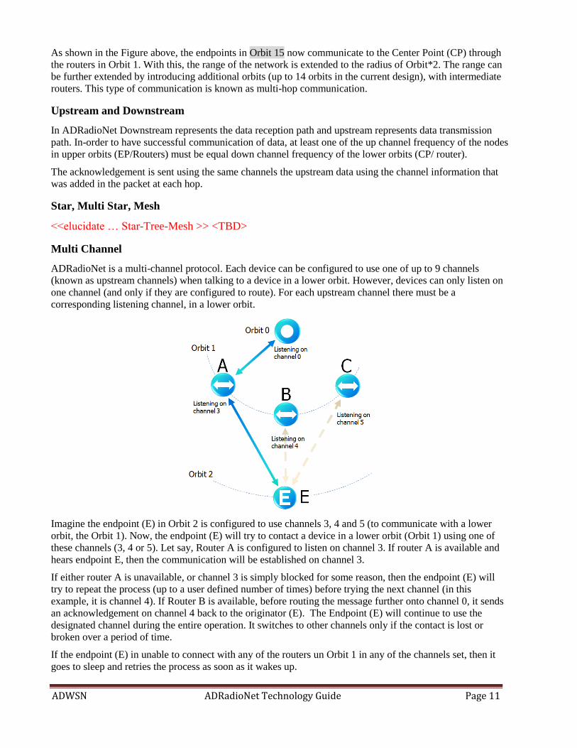
ADRadioNet is a multi-channel protocol. Each device can be configured to use one of up to 9 channels
(known as upstream channels) when talking to a device in a lower orbit. However, devices can only listen on
one channel (and only if they are configured to route). For each upstream channel there must be a
corresponding listening channel, in a lower orbit.
Imagine the endpoint (E) in Orbit 2 is configured to use channels 3, 4 and 5 (to communicate with a lower
orbit, the Orbit 1). Now, the endpoint (E) will try to contact a device in a lower orbit (Orbit 1) using one of
these channels (3, 4 or 5). Let say, Router A is configured to listen on channel 3. If router A is available and
hears endpoint E, then the communication will be established on channel 3.
If either router A is unavailable, or channel 3 is simply blocked for some reason, then the endpoint (E) will
try to repeat the process (up to a user defined number of times) before trying the next channel (in this
example, it is channel 4). If Router B is available, before routing the message further onto channel 0, it sends
an acknowledgement on channel 4 back to the originator (E). The Endpoint (E) will continue to use the
designated channel during the entire operation. It switches to other channels only if the contact is lost or
broken over a period of time.
If the endpoint (E) in unable to connect with any of the routers un Orbit 1 in any of the channels set, then it
goes to sleep and retries the process as soon as it wakes up.

ADWSN ADRadioNet Technology Guide Page 12
Address Binding
Address binding is used to bind the communication of data to a particular node address which is in the path
towards the CP. In normal operation mode, the data from the EP is always meant to reach the CP. In some
special cases user may want to bind data to an intermediate device (router). In such cases, this address binding
feature can be enabled by plugging in the bind address in the configuration and check the enable binding
button. Once the binding is enabled the data from the particular EP will not be forwarded to CP, instead it’s
bound to the node address given.
Message Components
UART Message Format
The following table shows the message structure that flows between ANode device and ANode Config /
Center point tools.
UART Header
UART Payload Data CRC
SYNCHBYTE0 SYNCHBYTE1 Length UART
Command
1 byte 1byte 1 byte 1 byte Max 122 bytes 2 bytes
The UART payload data comprises of,
The configuration data (EP or CP or Router) when communicating with ANode Config tool.
Sensor data (only CP) when communicating with the ANode Center Point tool.
Note: The RL78/G13’s UART0 is being used for communication between PC tools and ANode device.
Physical Layer Packet Components
Preamble Sync Payload
CRC Postamble Length Address Payload Data
1 byte to 256 bytes 1-24 bits 1 byte 1-9 bytes 0- 240 bytes 2 bytes 2 bytes
Packet format at MAC layer
SRD_BUFFER_SIZE (128 Bytes Max.)
LLH_LEN
(9 Bytes)
MB_MSGHEADLEN
(17 Bytes)
Payload
SensData Local statistics (35 Bytes)
Added if Local Statistics are enabled to send
Position mark #Bytes Value
LLH_LEN (9 Bytes)
LLH_PACKLEN_POS 1 LLH_LEN + Len
LLH_OPTS_POS 1 mConfigParams.MainOpts
LLH_SRCORBIT_POS 1 mConfigParams.Orbit
LLH_TYPEREPEAT_POS 1 mRunParams.RepeatCntr
LLH_SIGLEVEL_POS 1 (mRunParams.TxPwr * 100) / MAX_TX_PWR
LLH_PANID_POS 2 mRunParams.PanId
LLH_EXCH_ID_POS 2 mRunParams.LocExchID
Total 7

ADWSN ADRadioNet Technology Guide Page 13
MB_MSGHEADLEN (17 Bytes)
MB_MSG_INDEX (2B) 2 MsgIndex
MB_ORBIT_POS (1B) 1 mConfigParams.Orbit
MB_DESTADR_POS (8B) 8 mConfigParams.AdrAry
MB_NWTIME_POS (4B) 4 mRunParams.NW_SynTime
MB_PORT_POS (2B) 2 Port
Total 17
Local statistics (35 Bytes)
STRK_ID_STATS 1 S
Message Counter Stat. 5 mRunParams.StatMsgCntr
Bad Message Counter Stat. 5 mRunParams.StatBadMsgCntr
Message Duration Stat. 3 mRunParams.StatMsgDuration
Tx Duration Stat. 3 mRunParams.StatTxDuration
CCA Duration Stat. 3 mRunParams.StatCCADuration
Message Not Sent Stat. 3 mRunParams.StatMsgNotSent
Active Up-Channel Index 2 mConfigParams.UpChanNoAry[mRunParams.ActUpConnNo]
RSSI pack 2 mRunParams.RSSI_PackRx
Transmit Power (%) 2 (mRunParams.TxPwr * 100) / MAX_TX_PWR
Rx Repeats Stat. 2 mRunParams.StatRxRepeats
RSSI PHY ON 2 mRunParams.RSSI_PHY_on
BatVolt 3 mRunParams.BatVolt
Total 36

ADWSN ADRadioNet Technology Guide Page 14
Sending OTA Commands
<< Some of these are removed in v2.0?. cross check & add/modify/update>
Over The Air Commands issue form Center Point unit and are meant for modifying/controlling certain
parameters of the registered devices in the network.
Following are the OTA commands that implemented in the ADRadioNet.
Force a registration
This command requests the Endpoint / Router device to re-register to the network. This is useful in the cases
where the CP doesn’t have registration information of specific device (wondering why that happens? It can
happen, when the CP tool is started after the whole network is up).
Mute node (ignored by endpoints)
This command is useful when you don’t wish to receive data from a specific device. Useful in cases where a
router sends heartbeat but there is no data coming from any EP via that router can be annoying. That can be
muted.
Unmute node (ignored by endpoints)
This re-enables the data communication from the nodes that were muted earlier.
Change sleep time
Sleep time of specific End Point can be changed by passing the sleep period in milliseconds. User must issue
Save Configuration Command in-order to save this sleep time in ROM before the unit is reset.
Reset local statistics
This command is to reset the local statistics like packet number, Bad message count and other transceiver
statistics
Set PWM0 duty cycle (0...100%)
This command sends duty cycle (in 0 to 100% range) as parameter to the endpoint, which the Endpoint uses
to generate the PWM output.
Reset node
This command resets the specific node.
Enable low power mode (ignored by routers)
This command enables the low power mode (power saving mode) of operation on a specific node.
Disable low power mode
This command disables the low power mode (power saving mode) of operation on a specific node.
Enable local statistics
This command is issued to the node if the CP wishes to receive the statistics like packet number, Bad
message count and other transceiver parameters.
Disable local statistics
This command is issued to the node if the CP doesn’t wish to receive the statistics like packet number, Bad
message count and other transceiver parameters.
Save configuration (use with caution)
This command is issued in-order to save the configuration parameters of specific node in its ROM to use it
from the next power up cycle.

ADWSN ADRadioNet Technology Guide Page 15
Routing and Addressing
Routing
The routing mechanism used in ADRadioNet is stateless and has similarities to a DODAG (destination
orientated directional acyclic graph), which ensures directionality in the network. Each device has an orbit
number from 0 to 15 which indicates its position within the network (endpoints are at orbit 15 and center
points are at orbit 0). Routers are assigned an orbit from 1 to 14. If no routers are available the network
naturally forms a star. Data flows from the outer orbits to the inner orbits, this is ensured by the application of
the simple rule: Each message contains the orbit number of the device that just transmitted it and can only be
accepted (acknowledged) by a device in a lower orbit.
There are no conveyance messages e.g. router solicitation, neighbor discovery etc. or administration messages
in ADRadioNet.
Addressing
Ideally a network should assume no prior knowledge of available resources but exhaust the resources that
exist at that moment in time. By eliminating local link addressing ADRadioNet does exactly that. This
reduces latency and traffic congestion.
All messages contain a 64 bit (EUI-64) address (and a 16 bit port number, which together form an IP socket).
There are no link local addresses, rather unique (pseudo-random) identifiers are used to form links at a local
level. This eliminates routing tables.
Each message contains transmit power and number of resends. A receiving node combines this information
with receive signal strength to decide if the message should be acknowledged. Illustrated in Figure below, a
low power device, Node A, transmits a message. Both Node B and Node C receive this message. Node B
acknowledges using the same unique identifier from the original message. Consequently Node A can go back
to sleep immediately. Node C ignores the message as the first attempt is considered too weak.

ADWSN ADRadioNet Technology Guide Page 16
However if node B is not available, then node A resends the message. Node C now decides that it should
acknowledge, as this is the second attempt (see Figure below). Normally Node A would progressively
increase its own transmit power for the second attempt and subsequent attempts. The important point to note
here is no local addressing is used which results in no possible path being ignored. Any path is better than no
path. The routing law, based on the orbit numbers, applies here. That means Node B and Node C must be in a
lower orbit than Node A.
Even if two nodes were to simultaneously respond, then the net effect is that the same message is routed
through the network. Each message contains a monotonic marker which ensures that duplicates are rejected.
Duplicate messages are an important indication of how well resources are distributed in a network. They can
only exist when non-independent paths overlap which degrades all wireless networks regardless of protocol.
This information can then be used in the self-organizing scheme for optimization (e.g. switching channels
and/or reducing maximum transmit power).

ADWSN ADRadioNet Technology Guide Page 17
Elucidating Configuration Settings
Basic Configuration Parameters:
Node Function:
EndPoint: Sensor Mote, collects data from sensors and transmits to Center Point on Upstream PHY (via
Router). Spends majority of time in low power (sleepy) mode.
Router: Routes data received on Downstream PHY to Upstream PHY. Can be placed in any orbit from 1
to 15 to extend the range. Usually mains powered (powered all the time) and are thus not low power,
typically drawing 12mA.
CenterPoint: The data collector unit, destination node for all the data in PAN. Placed at the 0th orbit,
receives data on the downstream PHY. Mains powered, usually connected to gateway or cloud.
Sniffer: Sniffs the packets on the downstream PHY & channel selected and displays on the monitoring
tool.
Frequency of Operation (ISM Bands)
ADRadioNet© is designed to operate in any frequency range – be it Sub-GHz or 2.4GHz. The existing
implementation from Analog Devices supports the following three ISM frequency bands:
o European 868MHz ISM band.
10 channels, starting with frequency of 868MHz and channel spacing of 200 kHz.
o European 433MHz ISM band.
10 channels, starting with frequency of 433MHz and channel spacing of 200 kHz.
o USA 915MHz ISM band.
10 channels, starting with frequency of 915MHz and channel spacing of 200 kHz.
Other than the default 200 kHz channel spacing, the EDK provides an option to use 400 kHz or 600 kHz as
channel spacing of choice (as compile time option).
Up Channels & Down Channels
The ADRadioNet© protocol defines 10 channels in each ISM band. On a given node, any channel or all
channels can be chosen for upstream communication, and for downstream one channel has to be chosen. For
example one may choose the first channel (channel#0) as Down Channel - to receive the data form upper
orbits, and the remaining 9 channels can be used to transmit data to lower orbits. (a.k.a Up Channels).
It shall be noted that there is no down channel for endpoints or no up channel for center point. This is because
the end points will be positioned in the outermost orbit and obviously won’t be allowed to receive any data
from the next higher orbits. Likewise as the center point does not have any other lower orbit, it doesn’t require
any up channel.
Device Address
Each device must have a unique MAC address. The PC tool ANodeConfig allows direct manipulation of the
MAC address for evaluation purposes, and shall be blocked in the production releases.
ADRadioNet© aligns itself with EUI-64. The standard address suggested on default is based on the Analog
Devices global EUI-48 identifier (00-05-F7) (see http://standards.ieee.org). This identifier is converted to a
global EUI-64 identifier by adding the FF FE bytes in the middle resulting in the default address:
00 05 F7 FF FE F0 00 00 00

ADWSN ADRadioNet Technology Guide Page 18
This is merely a suggestion to start a network with, for production purposes a EUI-64 identifier shall be
obtained from the IEEE statutory body which allows the creation of a globally unique device address.
The over the air (OTA) packages in the ADRadioNet protocol use the EUI-64 addresses, there is no
translation to short addressing. This is possible due to the unique routing mechanism used in this protocol.
Two APIs manage manipulation of the device address.
Procedure name ANode_GetAdrAry
Input parameter Type ADRTYPE.
Returns A pointer to the address array of either the node (ADR_MY) or the device that the
node is bound to (ADR_BIND).
Purpose This API is used to get a pointer to the byte array containing the MAC address
(ADR_MY) or the bind address (ADR_BIND).
Note: The address is sent most significant byte and the most significant bit first.
PAN identifier
To enable independent networks to coexist, each must be given a unique identifier. This condition is relevant
in cases where two neighboring networks can hear each other. Consequently each OTA package contains a
PAN identifier (8 bits), this allows up to 255 networks to coexist, all within earshot of each other (as a point
of interest most other protocols use a 2 byte value). Only devices that are configured as central points are
assigned PAN identifiers during the configuration. All other devices are assigned the PAN identifier of the
central point when they join the network.
Note: If over time networks with the same PAN identifier “grow” towards each other, it’s possible to block
the routing of non-indigenous messages at a local level (see message filtering), alternatively a new PAN
identifier can be reassigned to the network, this is a more tedious process requiring that all devices rejoin the
network.
Binding
Address binding is used to bind the communication of data to a particular node address which is in the path
towards the CP. In normal operation mode, the data from the EP is always meant to reach the CP. In some
special cases user may want to bind data to an intermediate device (router). In such cases, this address binding
feature can be enabled by plugging in the bind address in the configuration and check the enable binding
button. Once the binding is enabled the data from the particular EP will not be forwarded to CP, instead it’s
bound to the node address given.
<<?? This feature is not supported in v2.0; taken out & to be put back>
Sleep Time
The sleep time variable applies to end points and the minimum sleep time supported by the protocol is 1 sec.
Number of Repeats
This controls the number of times the EP/router tries to send data on a particular channel before trying the
next channel.
Not Sleepy
<To be updated>
AES128 Key:
< To be updated>

ADWSN ADRadioNet Technology Guide Page 19
PHY Parameters:
Max TX Power:
<< To be updated>
CCA Limit:
<<To be updated>
RSS limit:
<<To be updated>
AES128 Key:
<<To be updated>
Repeats before Sleep:
<<To be updated>
Repeats before lost:
<<To be updated>
Protocol Parameters:
Authenticate time stamp:
<<To be updated>
Secure link:
<<To be updated>
Enable Auto TX power:
<<To be updated>
Self-Organizing:
<<To be updated>
No PAN ID:
<<To be updated>
Repeats before lost:
<<To be updated>
Device Description:
<<To be updated>

ADWSN ADRadioNet Technology Guide Page 20
Network Formation
Joining the Network
When a WSN device or mote is powered-up (or reset) it will try to join a network in the vicinity it is present.
The following sequences of events happen:
1. The device transmits a block of information about itself.
2. As the device does not know the identifier of the network, it uses a wild card identifier.
3. Requests an acknowledgement that the message arrived at the center point.
Lost Network
Once the device is in the network, it expects to be acknowledged for each message at the local link level. If
there is no acknowledgement then then the message is re-transmitted (repeated for 3 times in default mode).
If there is no acknowledgment even after these retries, then the process is repeated on next preset channel
(assuming the device is configured for more than one channel). If after repeated attempts on all channels fail
to get acknowledgement, then it is considered that the device is out of network or lost. In such a case the
device goes into sleep mode and repeats the procedure right after it wakes up next time.
Departing the Network
<<explain >>
ADWSN ADRadioNet Technology Guide Page 21
Application Programming Interface
API’s Explained
The ADRadioNet provides an easy to use application programmers interface broadly classified in to
the following 5 categories
API_SET_1: Configuration & Initialization
API_SET_2: Protocol State Machine
API_SET_3: Data Communication
API_SET_4: Low power operation
API_SET_5: PC tool interface & control
API_SET_1: Configuration & Initialization
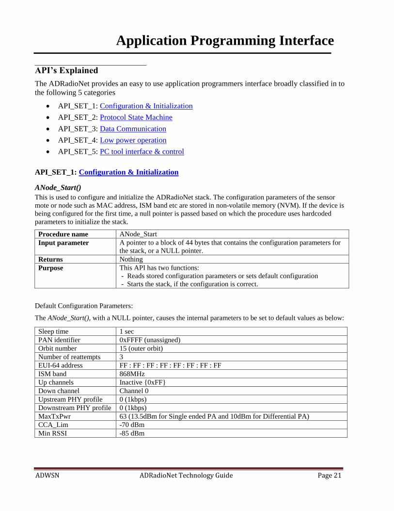
ANode_Start()
This is used to configure and initialize the ADRadioNet stack. The configuration parameters of the sensor
mote or node such as MAC address, ISM band etc are stored in non-volatile memory (NVM). If the device is
being configured for the first time, a null pointer is passed based on which the procedure uses hardcoded
parameters to initialize the stack.
Procedure name ANode_Start
Input parameter A pointer to a block of 44 bytes that contains the configuration parameters for
the stack, or a NULL pointer.
Returns Nothing
Purpose This API has two functions:
- Reads stored configuration parameters or sets default configuration
- Starts the stack, if the configuration is correct.
Default Configuration Parameters:
The ANode_Start(), with a NULL pointer, causes the internal parameters to be set to default values as below:
Sleep time 1 sec
PAN identifier 0xFFFF (unassigned)
Orbit number 15 (outer orbit)
Number of reattempts 3
EUI-64 address FF : FF : FF : FF : FF : FF : FF : FF
ISM band 868MHz
Up channels Inactive {0xFF}
Down channel Channel 0
Upstream PHY profile 0 (1kbps)
Downstream PHY profile 0 (1kbps)
MaxTxPwr 63 (13.5dBm for Single ended PA and 10dBm for Differential PA)
CCA_Lim -70 dBm
Min RSSI -85 dBm

ADWSN ADRadioNet Technology Guide Page 22
ANode_UpdateConfig()
This API used to update the stack parameters with the configuration stored in mConfigParams structure.
This procedure is called from ANode_Start() before initializing the stack. This API can be used to update the
stack with new configuration parameters at any later stage.
Procedure name ANode_UpdateConfig
Input parameter None
Returns Nothing
Purpose This API loads the parameters into the protocol state machine. It is called
automatically by the ANode_Start(). However if the user desires to update any
protocol parameters at any given time, then this API must be called again for the
new updates to takes effect.
Contents of the configuration data
A global structure named mConfigParams is created to hold the configuration parameters as below.
Parameter Identifier Description
Sleep time SleepTime_ms While this parameter is not strictly part of the wireless protocol,
it’s included for convenience. This parameter is a multiple of
125ms e.g. 8 = 1s. The protocol wakes on this interval. If the
device is configure as a router then this parameter is used to
send a heartbeat message as the case may require.
EUI-64 address AdrAry[] Each device requires a unique identifier to participate in the
network. This is specified by the EUI-64 address.
Binding address BindAdrAry[]
PAN identifier PANID[2] This is a byte value, used to separate neighboring networks. If
this value does not correspond to the value in the receiving
node, the message is dropped.
Orbit number Orbit Each device belongs to an orbit. Orbit zero is configured as the
center point (base station). There can only be one device per
channel in orbit 0. Only devices in higher orbits can initiate
communicate with devices in lower orbits.
Number of reattempts RepeatLimit Each message must be acknowledged. If no acknowledgement
is received the message is repeated up to the value specified
with this parameter (max. 16 times), before going back to sleep
and repeating trying later.
ISM band This defines which ISM band is selected. The hardware must
support the selection.
Up channels The devices can initiate communicate with routing enabled
devices in lower orbits through one of the up (stream) channels.
Up to 9 up channels can be defined per device.
Down channel A device responds on its down (stream) channel to any
upstream messages. Currently only one downstream channel
per device is supported.
Up channel PHY There are a number of PHY configurations supported. See
Physical Layer Profiles below.
Down channel PHY There are a number of PHY configurations supported. See
Physical Layer Profiles below.
Repeats Till Lost RepeatsTillLost Number of repeats before node reconfigures itself
Max Tx Power MaxTxPwr
CCA_Lim
ADWSN ADRadioNet Technology Guide Page 23
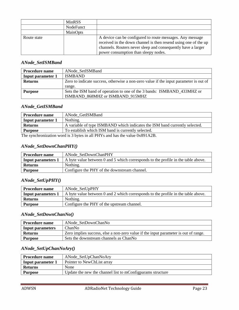
MinRSS
NodeFunct
MainOpts
Route state A device can be configured to route messages. Any message
received in the down channel is then resend using one of the up
channels. Routers never sleep and consequently have a larger
power consumption than sleepy nodes.
ANode_SetISMBand
Procedure name ANode_SetISMBand
Input parameter 1 ISMBAND
Returns Zero to indicate success, otherwise a non-zero value if the input parameter is out of
range.
Purpose Sets the ISM band of operation to one of the 3 bands: ISMBAND_433MHZ or
ISMBAND_868MHZ or ISMBAND_915MHZ
ANode_GetISMBand
Procedure name ANode_GetISMBand
Input parameter 1 Nothing.
Returns A variable of type ISMBAND which indicates the ISM band currently selected.
Purpose To establish which ISM band is currently selected.
The synchronization word is 3 bytes in all PHYs and has the value 0x891A2B.
ANode_SetDownChanPHY()
Procedure name ANode_SetDownChanPHY
Input parameters 1 A byte value between 0 and 5 which corresponds to the profile in the table above.
Returns Nothing.
Purpose Configure the PHY of the downstream channel.
ANode_SetUpPHY()
Procedure name ANode_SetUpPHY
Input parameters 1 A byte value between 0 and 2 which corresponds to the profile in the table above.
Returns Nothing.
Purpose Configure the PHY of the upstream channel.
ANode_SetDownChanNo()
Procedure name ANode_SetDownChanNo
Input parameters ChanNo
Returns Zero implies success, else a non-zero value if the input parameter is out of range.
Purpose Sets the downstream channels as ChanNo
ANode_SetUpChanNoAry()
Procedure name ANode_SetUpChanNoAry
Input parameter 1 Pointer to NewChList array
Returns None
Purpose Update the new the channel list to mConfigparams structure

ADWSN ADRadioNet Technology Guide Page 24
ANode_SetDownPHY()
Procedure name ANode_GetUpChanNoAry
Input parameter Node.
Returns Address of a 9 byte array containing the upstream channels numbers.
Purpose Define the upstream channels for a node. A valid channel number is currently 0-8.
An unused channel number is defined as 0xFF. At least one valid upstream channel
must be defined. The first undefined channel in the list signifies end of the list.
ANode_SetDeviceType()
Procedure name ANode_SetDeviceType
Input parameter 1 Long integer (32 bit) which defines the type of device.
Returns None.
Purpose This value is not used by the protocol and is included for convenience only.
ANode_SetOrbit()
Procedure name ANode_SetOrbit
Input parameter Orbit number, this is a byte value from 0 to 15. Setting this value to 0 has the effect
of forcing the node to be a center point
Returns Zero denotes success, else a non-zero value if the input parameter is out of range.
Purpose Set the orbit number of the device. See the chapter on orbits for more information.

ADWSN ADRadioNet Technology Guide Page 25
API_SET_2: Protocol State Machine
ANode_Main()
ANode_Main() is the main API in ADRadioNet© , this is a non-blocking procedure that is must be regularly
called* when the stack is active. This API returns the current state of the stack. The following table shows all
possibly states
Returning the stack state allows interaction between application and wireless network. If the standard
behavior of the network is suitable then there is no need to react to any of these states.
State Node type Meaning
ANS_ASLEEP End point Transceiver is powered down and the stack is
inactive.
ANS_AWAKE End point The stack is now active.
ANS_GOING_TO_SLEEP End point This state is issued just before the transceiver
powers down and the stack becomes inactive
ANS_STAY_LISTENING This state is returned when low power mode is
disabled and transceiver finished a transaction.
ANS_WAKING_UP End point Transceiver is about to be powered-up and the stack
will become active.
ANS_UPSTREAM_DATA Router A valid data package has been received from a node
in a higher orbit.
ANS_DOWNSTREAM_DATA End point
and Router
A valid data package has been received from a node
in a lower orbit.
ANS_SELFORGANISING All Device is searching for it’s position in the network.
ANS_HW_PROBLEM All Problems with the transceiver, could indicate an
invalid configuration.
ANS_NOT_CONFIG All Configuration data invalid
ANS_LOST_CONTACT End point
and Router
Node has lost contact with the network

ADWSN ADRadioNet Technology Guide Page 26
ANode_Tick()
Procedure name ANode_Tick
Input parameter None
Returns None
Purpose Manages the timing threads in the protocol. This procedure must be called on at a
regular interval in awake state to ensure the state machine operates correctly.
ModeControl()
Procedure name ModeControl() Input parameter Returns Purpose
Manages the device modes
<<JC to expand more… Very IMP>
ANode_SelfHeal()
Procedure name ANode_SelfHeal() Input parameter None Returns None Purpose Checks if the next channel should be selected (based on repeat limit selected by
user while configuring), then select the next channel to establish connection
with node on upstream path (or to send data to router or CP)
ANode_SRDEventHandler() << explain more on PHYEVENTS responses>
Procedure name SRDEventHandler()
Input parameter
Returns PHYEVENTS SRDResp; explained in table below.
Purpose

ADWSN ADRadioNet Technology Guide Page 27
API_SET_3: Data Communication – Sending & Receiving data.
Transmitting a message:
There are three steps necessary to send a message:
1. Check if the stack is ready to send a message by calling the ANode_CheckState() API
2. If the first step is positive, then place the message in the transmit buffer
3. Call the ANode_SendMessage() API
The main APIs that govern this process are listed below:
ANode_CheckState()
Procedure name ANode_CheckState
Input parameter A byte with a thread identifier. The actual value is not important but must be in the
range 0 to 250. The purpose of this variable is to support more than one data
exchange – the paragraphs below will provide a more in-depth explanation
Returns A result of type MSGSTATES, see table below
Purpose Check if the stack is ready to transmit a message
MSGSTATES Meaning Application use
MS_NOTRDY Stack is not ready to transmit a message. This
could be due to a number of reasons e.g. the
stack is not awake.
Can be ignored.
MS_OK2TX Okay now to transmit a message. Yes, the data can be loaded into the
transmit buffer and the
ANode_SendMessage() API can be
called
MS_WAITING Message has been transmitted and the stack is
waiting for a reply.
Can be ignored.
MS_REPLY An acknowledgement was received. Can be ignore as the ANode_Main()
returns an appropriate state if valid
data has been received.
MS_TO No reply was received within the time-out
period
Can be ignore, or used to decide
what action is now necessary.
ANode_TxBuffer()
Procedure name ANode_TxBuffer
Input parameter None,
Returns Return a pointer to a byte array – which is the transmit buffer.
Purpose Get a pointer to the transmit buffer, which can then be filled with data.
ANode_SendMessage()
Procedure name ANode_SendMessage
Input parameter 1 Pointer to the byte array containing the data to transmit.
Input parameter 2 A short integer value – 16 bit specifying to which port the data should be sent.
The destination address is not specified as all messages are directed towards the
center point.
Input parameter 3 A variable of type ACKNOWLEDGETYPE (see table below) which specifies
what type of acknowledgement is required.

ADWSN ADRadioNet Technology Guide Page 28
Returns An integer which is zero if the transmissions correctly executed or non-zero if
otherwise.
Purpose Get a pointer to the transmit buffer, which can then be filled with data.
ACKNOWLEDGE TYPE Meaning Application use
AT_NONE No acknowledgement from the center point is
required that the message arrived.
Yes
AT_E2E An acknowledgement from the central point is
required when the message arrives there.
Yes
Receiving a message:
<<JC to expand more… Very IMP>

ADWSN ADRadioNet Technology Guide Page 29
API_SET_4: Low power Operation.
ADRadioNet has a power management facility which tries to minimize the amount of power required for
endpoint devices (which are often battery powered). The protocol manages the transceiver power directly and
informs the power status to the system. These states are only available in endpoint devices. The power
management states are returned from the ANode_Main() API and have the following meanings:
ANode_Main() return state Meaning to an end device*
ANS_SLEEP Protocol is in an idle state, transceiver (and other associated circuitry) is
powered down. Current consumption is ca. 2µA.
ANS_WAKING_UP This is a transient state to inform the system that the protocol is about to
become active.
ANS_AWAKE Protocol is busy servicing a communication thread. Exact power consumption
depends on the exact state of the communication and can vary from 4mA to
25mA. A soon as the protocol has nothing to do it will power down. However
the protocol can be forced to stay awake for a certain time period by calling the
ANode_StayaWake() API.
ANS_GOING_TO SLEEP This is a transient state to inform the system that the protocol is now going into
idle mode.
*Consumption figures based on the ADF702x without a power amplifier.
Enabling/disabling the power management feature
The power management feature has two states, either enabled or disabled, these states are represented by 5th
bit of MainOpts configuration parameter. An endpoint device can only benefit from the power management
features if they are enabled. Enabling / disabling this low power mode is done by the checking / unchecking
“Not Sleepy” option on ANode Configuration tool while configuring the endpoint.
ADWSN ADRadioNet Technology Guide Page 30
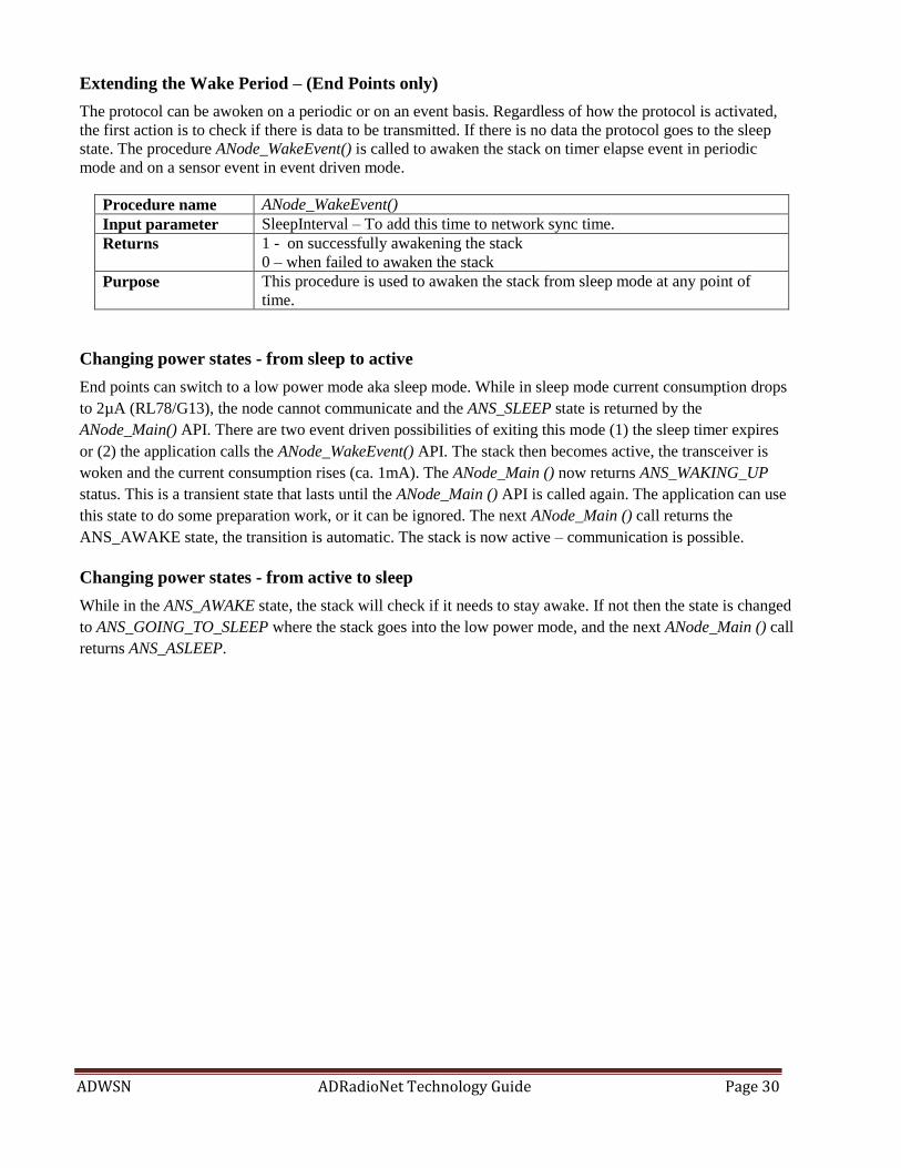
Extending the Wake Period – (End Points only)
The protocol can be awoken on a periodic or on an event basis. Regardless of how the protocol is activated,
the first action is to check if there is data to be transmitted. If there is no data the protocol goes to the sleep
state. The procedure ANode_WakeEvent() is called to awaken the stack on timer elapse event in periodic
mode and on a sensor event in event driven mode.
Procedure name ANode_WakeEvent()
Input parameter SleepInterval – To add this time to network sync time.
Returns 1 - on successfully awakening the stack
0 – when failed to awaken the stack
Purpose This procedure is used to awaken the stack from sleep mode at any point of
time.
Changing power states - from sleep to active
End points can switch to a low power mode aka sleep mode. While in sleep mode current consumption drops
to 2µA (RL78/G13), the node cannot communicate and the ANS_SLEEP state is returned by the
ANode_Main() API. There are two event driven possibilities of exiting this mode (1) the sleep timer expires
or (2) the application calls the ANode_WakeEvent() API. The stack then becomes active, the transceiver is
woken and the current consumption rises (ca. 1mA). The ANode_Main () now returns ANS_WAKING_UP
status. This is a transient state that lasts until the ANode_Main () API is called again. The application can use
this state to do some preparation work, or it can be ignored. The next ANode_Main () call returns the
ANS_AWAKE state, the transition is automatic. The stack is now active – communication is possible.
Changing power states - from active to sleep
While in the ANS_AWAKE state, the stack will check if it needs to stay awake. If not then the state is changed
to ANS_GOING_TO_SLEEP where the stack goes into the low power mode, and the next ANode_Main () call
returns ANS_ASLEEP.

ADWSN ADRadioNet Technology Guide Page 31
API_SET_5: PC tool interface & control
Communication with ADRadioNet PC tools: UART port on the device is used for communicating with the ADRadioNet PC tools and following section
explains the UART API’s.
UARTInit()
Procedure name UARTInit
Input parameter UrtBaudRates BR
Returns None
Purpose Initializes the UART with the baud rate (BR) passed. Default is 460800bps
UARTStatus()
Procedure name UARTStatus
Input parameter
Returns Returns one of the following UART states
Purpose
UART States Explained
UARTSTATES Meaning
UARTRDY UART is ready for transaction
UARTRXING UART in Receive mode
UARTRXERR UART receive error occurred
UARTTXING UART in Transmit mode
UARTTXFIN Transmit over UART finished.
UARTRXFIN A complete packet is received over UART
UARTRXCRLF UART Rx flag cleared.
UARTWU UART wake-up mode (applies to ADuCRF101 as the UART Rx pin has the capability
to wake up the MCU when configured as GPIO & enable interrupt on that pin).
*This feature is not available in RL78 MCU.
UARTTx()
Procedure name UARTTx
Input parameter Cmd – command to be placed in UART header after sync byte.
DataLen – Data length excluding header
Returns 0: If successfully transmitted data over UART
UART Error code: If failed to transmit data
Purpose To add header to UART packet and initiate the data transfer on UART.

ADWSN ADRadioNet Technology Guide Page 32
UARTRxPayloadLen()
Procedure name UARTRxPayloadLen
Input parameter None
Returns UART payload length from the data received on UART port
Purpose This function retrieves the payload length from the packet received from
UART.
UARTTxBufferEnd()
Procedure name UARTTxBufferEnd
Input parameter None
Returns Returns the maximum number of bytes can be placed in UART buffer
Purpose This function is used to calculate the number of bytes that can be added to the
UART buffer.
GetUARTCmd()
Procedure name GetUARTCmd
Input parameter None
Returns Retrieves the command from the packet received from UART
Purpose Retrieves the command from the packet received from UART and returns to
user application to execute it.
UARTHandler()
Procedure name UARTHandler
Input parameter None
Returns None
Purpose Called in main while(1) loop to handle/manage the events occur on UART
Timer Usage:
Two timers are used to manage the periodicity in the protocol. RTC is used to for generating large period
interval (usually for sleep duration) and Channel#0 of Timer Array unit0 for small period intervals (for
transactions when the node is awake).
Following are the procedures used in managing the periodicity.
ChngeSysTimeDomain()
Procedure name ChngeSysTimeDomain
Input parameters SYS_WAKE_MODES AwakeMode – system power mode
U32 SleepInterval – sleep interval
Returns Returns the system power mode
Purpose Changes the time domain to awake or sleep mode based on AwakeMode
param.
Config_TAU0_CH0_uS
Procedure name ChngeSysTimeDomain
Input parameters Period – in micro seconds
Returns None
Purpose Configures the channel-0 of Timer Array Unit-0 to generate the interval given
by param Period.

ADWSN ADRadioNet Technology Guide Page 33
OTA Commands:
Following are the functions that execute the OTA commands sent from the CenterPoint.
ANet_CmdA()
Procedure name ANet_CmdA
Input parameters DATASOURCE WhichSrc
Returns Returns the position of buffer till the data is filled.
Purpose Fills the Tx buffer (based on WhichSrc) with the basic configuration content
and node description;
If WhichSrc is DS_OTA, mSRDTxPackBuffer will be filled with this
information which will be given to ANode_SendMessage for transmit OTA;
If WhichSrc is DS_UART, TxBuffer (for UART) will be filled with this
information to send to ADRadioNet PC tools via UART.
ANet_CmdB()
Procedure name ANet_CmdB
Input parameters DATASOURCE WhichSrc
Returns None
Purpose Reads and fills the UART Tx buffer with the internal transceiver (BBRAM)
settings to send to ANodeConfig tool.
ANet_CmdD()
Procedure name ANet_CmdD
Input parameters DATASOURCE WhichSrc
Returns None
Purpose Mutes the node / disables the upstream path
ANet_CmdE()
Procedure name ANet_CmdE
Input parameters DATASOURCE WhichSrc
Returns None
Purpose Resets the node
ANet_CmdSysStr ()
Procedure name ANet_CmdSysStr
Input parameters DATASOURCE WhichSrc
Returns None
Purpose Get or set one of the two system strings
Node description or URL

ADWSN ADRadioNet Technology Guide Page 34
Deep Dive into ADRadioNet
Main State Machine
The main state machine in ADRadioNet revolves around a procedure known as ANode_Main(), where in the
following two procedures are called before any state is evaluated:
ModeControl()
ANode_Tick()
<<Explain this more explicitly, rewrite the entire chapter and organize in a better way>>
The other procedure ModeControl() is responsible for changing the modes of the devices i.e. changing the
coordinator from B to C and vice versa as well as waking and putting to sleep the endpoints. A coordinator
should spend the majority of its time in the C mode listening for upstream messages, changing to B mode
only if there is a message to relay upstream. Before changing from C to B the following checks have to be
performed:
Is there valid data to send upstream?
Is the message received from a valid higher orbit (will eventually depend on the direction bit)?
Is the node muted?
Mode Control
The xxx <<start from timing fundamental document, add more; more clarity to be given; rewrite…>>
The coordinator starts-up in B mode. If a connection is made to a lower orbit, it changes it’s attachment state
to attached and the mode changes to C (PrepVars()). The following is a list of how the coordinator can change
modes:
1. Reset or power-up coordinator mode set to B
2. Attachment state changes to attached then mode changes to C
3. Valid upstream message received in C state, then mode can change to B
4. Valid message has been sent upstream, then mode changes from B to C
5. Time-out in the C mode. The timer is reset whenever data is sent upstream. If no valid data is received
then the sleep timer rolls-over causing the modes to change from mode C to mode B, consequently
sending a heartbeat upstream.
In C mode the RTC is running (sleep period). If the RTC interrupts the ModeControl() procedure sets a flag to
indicate that the coordinator state can change (if finished with the last exchange) and also sets an event marker
to indicate that this change was caused by an RTC event. The CoordinatorEPHandler() uses this information to
send a heartbeat message upstream, immediately changing back to mode C when this exchange is completed.
If the exchange cannot be completed then the coordinator changes its attachment state and will periodically try
to reattach.
Upstream traffic can also cause the coordinator to change to the B mode. This is done by setting a flag in the
event handler. The event handler is called on a regular basis, which ensures that the coordinator mode changes
to B and the message is relayed further upstream. If this flag is not set then the message is not relayed and the
coordinator stays in C mode until one of the above two events causes a mode change. At this stage the user can
filter upstream messages, with two exceptions: heartbeat messages are never relayed, and registration messages
always are.

ADWSN ADRadioNet Technology Guide Page 35
ModeControl
<<explain more; rewrite>>
This procedure is called at the start of the state machine. The main point of interest here is the
mRunParams.State system variable. This reflects the main state of the machine. It can have only two states
ANS_AWAKE and ANS_ASLEEP. A further parameter mRunParams.InitStateFlag indicates the start of a
timing domain and can have one of 3 values: RESETSLOTFLAG, INITAWAKESLOT or
INITASLEEPSLOT.
Awake state
The awake state is the initial state when the machine starts and also the only state when the system is in mode
B or D (CP). In mode A this state can be entered without regard to the other system states, a user or RTC
event activates this state. When the system is in mode C, then it must first switch to mode B before this state
can be enterer. Two events can cause this mode change: the reception of upstream data or an RTC event. Any
exchange must be firstly and properly finished – see lower nibble of the parameter mRunParams.CoOrdState.
There are 4 places in code where the awake state is entered:
1. during system initialization, regardless of mode,
2. if requested to go from mode B to mode C but not attached
3. the event handler,
4. and the timer ISR.
A clock tick for every 1msec is required in this state. A device in mode B must be registered to change to
mode C. An unregistered device in mode B must still obey the sleep times, as otherwise continuous traffic
could be generated thus overloading the system.
Asleep state
The asleep state has less implications. In mode A this state is entered only when the awake state is complete.
In mode B or D this state is never entered. In mode C, entering this state means changing modes from mode
B. The only gating factor in this case is to ensure that the device is attached as it makes little sense to be in
mode C without a routing possibility. There is only one place in code that the asleep state is entered namely
when the state machine is finished with a exchange. This can have 3 reasons, the exchange is properly
finished, the exchange timed-out, or the exchange never started.
The mRunParams.LoopCntr system variable ensures that the state machine loops through at least once. This
is necessary to ensure some states are check at least once.
The internal procedure iANode_CheckToSend() checks the state of the system variable
mRunParams.CommStage.
CommStage state Meaning
CS_SENDRDY The state machine is ready to transmit an upstream message.
CS_MESSAGE Indicates that an upstream message has been received.
CS_CHECKREPLY This is an immediate consequence of the state above. It allows the state machine
to present the above state externally, so that a check can be made if another
exchange is ready.
CS_TIMEOUT Timed-out before a downstream response.
CS_SENDING
ADWSN ADRadioNet Technology Guide Page 36
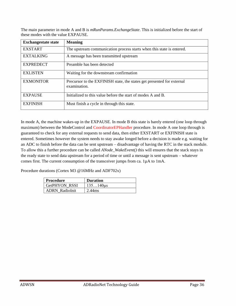
The main parameter in mode A and B is mRunParams.ExchangeState. This is initialized before the start of
these modes with the value EXPAUSE.
Exchangestate state Meaning
EXSTART The upstream communication process starts when this state is entered.
EXTALKING A message has been transmitted upstream
EXPREDECT Preamble has been detected
EXLISTEN Waiting for the downstream confirmation
EXMONITOR Precursor to the EXFINISH state, the states get presented for external
examination.
EXPAUSE Initialized to this value before the start of modes A and B.
EXFINISH Must finish a cycle in through this state.
In mode A, the machine wakes-up in the EXPAUSE. In mode B this state is barely entered (one loop through
maximum) between the ModeControl and CoordinatorEPHandler procedure. In mode A one loop through is
guaranteed to check for any external requests to send data, then either EXSTART or EXFINISH state is
entered. Sometimes however the system needs to stay awake longed before a decision is made e.g. waiting for
an ADC to finish before the data can be sent upstream – disadvantage of having the RTC in the stack module.
To allow this a further procedure can be called ANode_WakeEvent() this will ensures that the stack stays in
the ready state to send data upstream for a period of time or until a message is sent upstream – whatever
comes first. The current consumption of the transceiver jumps from ca. 1µA to 1mA.
Procedure durations (Cortex M3 @16MHz and ADF702x)
Procedure Duration
GetPHYON_RSSI 135…140µs
ADRN_RadioInit 2.44ms
ADWSN ADRadioNet Technology Guide Page 37
Radio Interface to Micro Controller
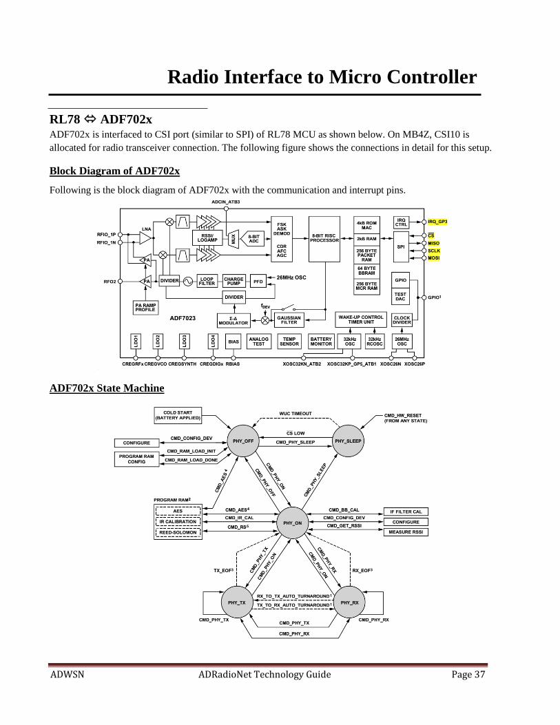
RL78 ADF702xADF702x is interfaced to CSI port (similar to SPI) of RL78 MCU as shown below. On MB4Z, CSI10 is
allocated for radio transceiver connection. The following figure shows the connections in detail for this setup.
Block Diagram of ADF702x
Following is the block diagram of ADF702x with the communication and interrupt pins.
ADF702x State Machine
ADWSN ADRadioNet Technology Guide Page 38
Driver Design
Development of this driver involves the following three steps.
1) CSI Interface
Code communicating with the HOST MCU SPI driver (CSI on RL78)
2) Radio Controller functionality
Issuing Commands (issuing commands to RC & reading the RC’s status)
Read/Write the entire memory range of Transceiver (incl. BBRAM, MCR & packet RAM)
Initialization functions
Framing the packet as per the PHY requirement
Interrupt management.
CSI Interface
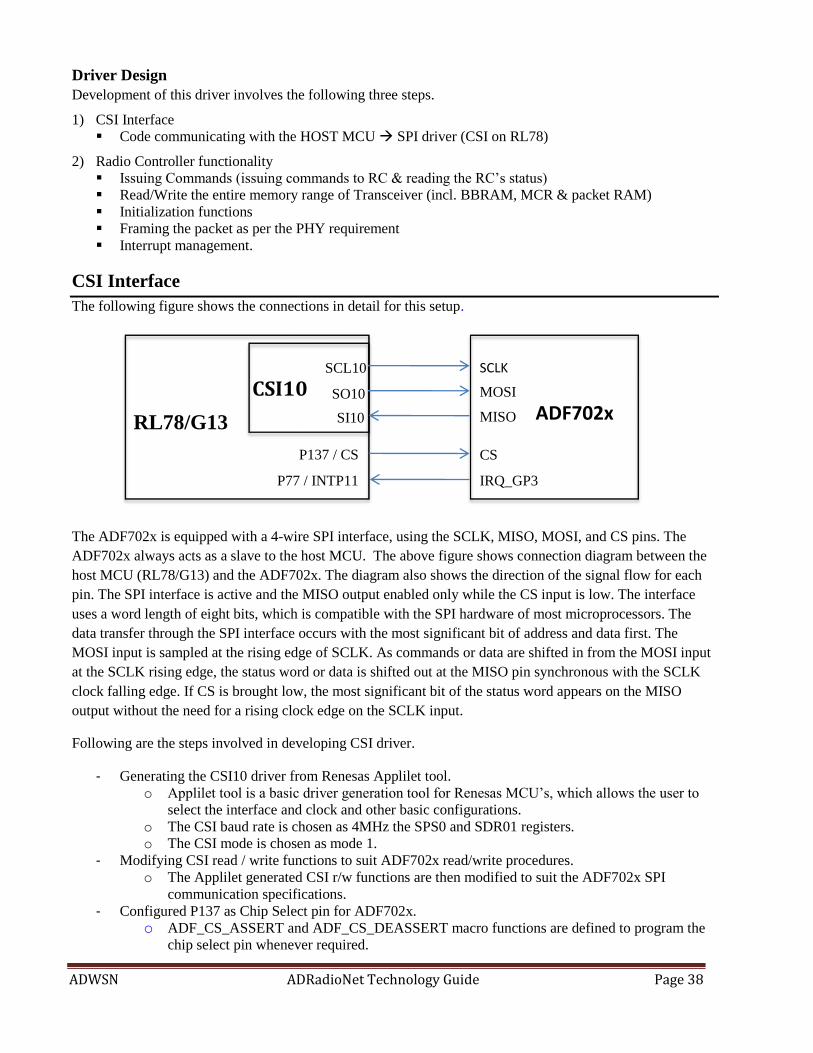
The following figure shows the connections in detail for this setup.
The ADF702x is equipped with a 4-wire SPI interface, using the SCLK, MISO, MOSI, and CS pins. The
ADF702x always acts as a slave to the host MCU. The above figure shows connection diagram between the
host MCU (RL78/G13) and the ADF702x. The diagram also shows the direction of the signal flow for each
pin. The SPI interface is active and the MISO output enabled only while the CS input is low. The interface
uses a word length of eight bits, which is compatible with the SPI hardware of most microprocessors. The
data transfer through the SPI interface occurs with the most significant bit of address and data first. The
MOSI input is sampled at the rising edge of SCLK. As commands or data are shifted in from the MOSI input
at the SCLK rising edge, the status word or data is shifted out at the MISO pin synchronous with the SCLK
clock falling edge. If CS is brought low, the most significant bit of the status word appears on the MISO
output without the need for a rising clock edge on the SCLK input.
Following are the steps involved in developing CSI driver.
- Generating the CSI10 driver from Renesas Applilet tool.
o Applilet tool is a basic driver generation tool for Renesas MCU’s, which allows the user to
select the interface and clock and other basic configurations.
o The CSI baud rate is chosen as 4MHz the SPS0 and SDR01 registers.
o The CSI mode is chosen as mode 1.
- Modifying CSI read / write functions to suit ADF702x read/write procedures.
o The Applilet generated CSI r/w functions are then modified to suit the ADF702x SPI
communication specifications.
- Configured P137 as Chip Select pin for ADF702x.
o ADF_CS_ASSERT and ADF_CS_DEASSERT macro functions are defined to program the
chip select pin whenever required.
SCLK
MOSI
MISO
CS
SCL10
SO10
SI10
P137 / CS
IRQ_GP3
CSI10
P77 / INTP11
ADF702x RL78/G13

ADWSN ADRadioNet Technology Guide Page 39
CSI Interface API’s
CSI10_Create()
- Configures the CSI10 for interfacing ADF.
- Selects CSI in mode #0
- Selects the CSI parameters baud rate, data width, and MSB first and.
CSI10_Start()
- Enables the CSI10 interface.
CSI10_Stop()
- Disables the CSI10 interface.
SPI_Tx_Rx(U8 *tx_buf, U16 tx_num, U8 *rx_buf)
- Initializes transfer of tx_num bytes from tx_buf as source.
- Receives tx_num bytes and stores in rx_buf.
- Enables CSI10 interrupt in case of multi-byte Tx/Rx.
CSI10_Interrupt (CSI10 interrupt handler)
- Handles multi-byte Tx/Rx until the tx_num of bytes transaction completed.
The ADF702x Driver
Once the CSI communication is up, the radio transceiver functionality is written according to specifications
mentioned in the ADF702x data sheet.
Issuing Commands to transceiver
First function to implement is command issue and read transceiver status.
The ADF702x is controlled through commands. Command words are single-byte instructions that control the
state transitions of the radio controller and access to the registers and packet RAM. Following list consists
some of the important commands.
Command (HEX command) Function
CMD_PHY_OFF (0xB0) Transitions 702x into PHY_OFF state
CMD_PHY_ON (0xB1) Transitions 702x into PHY_ON state
CMD_PHY_SLEEP (0xBA) Transitions 702x into very low power PHY_SLEEP state where the
BBRAM contents are retained
CMD_PHY_RX (0xB2) Transitions 702x into PHY_RX state
CMD_PHY_TX (0xB5) Transitions 702x into PHY_TX state
CMD_CONFIG_DEV (0xBB) This command interprets the BBRAM contents and configures each
of the radio parameters based on these contents. The user should
write to the entire 64 bytes of the BBRAM and then issue the
CMD_CONFIG_DEV command.
CMD_GET_RSSI (0xBC) This command turns on the receiver, performs an RSSI
measurement on the current channel, and returns the ADF702x to
the PHY_ON state. The command can be issued from the PHY_ON
state. The RSSI result is saved to the RSSI_READBACK register
(Address 0x312). This command can be issued from the PHY_ON
state only.

ADWSN ADRadioNet Technology Guide Page 40
CMD_BB_CAL (0xBE) This command performs an IF filter calibration
CMD_HW_RESET (0xC8) The command performs a full power-down of all hardware,
and the device enters the PHY_SLEEP state
CMD_RAM_LOAD_INIT (0xBF) This command prepares the communications processor for a
subsequent download of a software module to program RAM
CMD_RAM_LOAD_DONE
(0xC7)
This command is required only after download of a software
module to program RAM. It indicates to the communications
processor that a software module is loaded to program RAM.
CMD_IR_CAL (0xBD) This command performs a fully automatic image rejection
calibration on the ADF702x receiver.
The status word of the ADF702x is automatically returned over the MISO each time a byte is transferred over
the MOSI. Shifting in double SPI_NOP command causes the status word to be shifted out as shown in Figure
below.
The meaning of the various bit fields is illustrated in Table below.
The FW_STATE variable can be used to read the current state of the communications processor and is
described in Table below.
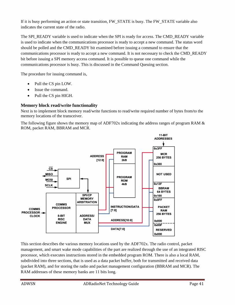
ADWSN ADRadioNet Technology Guide Page 41
If it is busy performing an action or state transition, FW_STATE is busy. The FW_STATE variable also
indicates the current state of the radio.
The SPI_READY variable is used to indicate when the SPI is ready for access. The CMD_READY variable
is used to indicate when the communications processor is ready to accept a new command. The status word
should be polled and the CMD_READY bit examined before issuing a command to ensure that the
communications processor is ready to accept a new command. It is not necessary to check the CMD_READY
bit before issuing a SPI memory access command. It is possible to queue one command while the
communications processor is busy. This is discussed in the Command Queuing section.
The procedure for issuing command is,
Pull the CS pin LOW.
Issue the command.
Pull the CS pin HIGH.
Memory block read/write functionality
Next is to implement block memory read/write functions to read/write required number of bytes from/to the
memory locations of the transceiver.
The following figure shows the memory map of ADF702x indicating the address ranges of program RAM &
ROM, packet RAM, BBRAM and MCR.
This section describes the various memory locations used by the ADF702x. The radio control, packet
management, and smart wake mode capabilities of the part are realized through the use of an integrated RISC
processor, which executes instructions stored in the embedded program ROM. There is also a local RAM,
subdivided into three sections, that is used as a data packet buffer, both for transmitted and received data
(packet RAM), and for storing the radio and packet management configuration (BBRAM and MCR). The
RAM addresses of these memory banks are 11 bits long.

ADWSN ADRadioNet Technology Guide Page 42
BBRAM
The battery backup RAM (BBRAM) contains the main radio and packet management registers used to
configure the radio. On application of battery power to the ADF702x for the first time, the entire BBRAM
should be initialized by the host processor with the appropriate settings. After the BBRAM has been written
to, the CMD_CONFIG_DEV command should be issued to update the radio and communications processor
with the current BBRAM settings. The CMD_CONFIG_DEV command can be issued in the PHY_OFF state
or the PHY_ON state only. The BBRAM is used to maintain settings needed at wake-up from sleep mode by
the wake-up controller. Upon wake-up from sleep, in smart wake mode, the BBRAM contents are read by the
on-chip processor to recover the packet management and radio parameters.
MODEM CONFIGURATION RAM (MCR)
The 256-byte modem configuration RAM (MCR) contains the various registers used for direct control or
observation of the physical layer radio blocks of the ADF702x. The contents of the MCR are not retained in
the PHY_SLEEP state.
PROGRAM ROM
The program ROM consists of 4kB of nonvolatile memory. It contains the firmware code for radio control,
packet management, and smart wake mode.
PROGRAM RAM
The program RAM consists of 2 kB of volatile memory. This memory space is used for software modules,
such as AES encryption, IR calibration, and Reed Solomon coding, which are available from Analog Devices.
The software modules are downloaded to the program RAM memory space over the SPI by the host
processor.
PACKET RAM
The packet RAM consists of 256 bytes of memory space. The first 16 bytes of this memory space are
allocated for use by the on-chip processor. The remaining 240 bytes of this memory space are allocated for
storage of data from valid received packets and packet data to be transmitted. The communications processor
stores received payload data at the memory location indicated by the value of the RX_BASE_ADRregister
(Address 0x125), the receive address pointer. The value of the TX_BASE_ADRregister (Address 0x124), the
transmit address pointer, determines the start address of data to be transmitted by the communications
processor. This memory can be arbitrarily assigned to store single or multiple transmit or receive packets,
with and without overlap. The RX_BASE_ADRvalue should be chosen to ensure that there is enough
allocated packet RAM space for the maximum receiver payload length.
Memory locations are accessed by invoking the relevant SPI command. An 11-bit address is used to identify
registers or locations in the memory space. The most significant three bits of the address are incorporated into
the SPI command by appending them as the LSBs of the command word.

ADWSN ADRadioNet Technology Guide Page 43
The above figure illustrates command, address, and data partitioning. The various SPI memory
access commands are different, depending on the memory location being accessed (see Table
below).
An SPI command should be issued only if the SPI_READY bit in the INTERRUPT_SOURCE_1 register
(Address 0x337) of the status word bit is high. The ADF702x interrupt handler can be also be configured to
generate an interrupt signal on IRQ_GP3 when the SPI_READY bit is high. An SPI command should not be
issued while the communications processor is initializing (FW_STATE = 0x0F). SPI commands can be
issued in any other communications processor state, including the busy state (FW_STATE = 0x00). This
allows the ADF702x memory to be accessed while the radio is transitioning between states.
MCR, BBRAM, and packet RAM memory locations can be written to in block format using the
SPI_MEM_WR command. The SPI_MEM_WR command code is 00011xxxb, where xxxb represent
Bits[10:8] of the first 11-bit address. If more than one data byte is written, the write address is automatically
incremented for every byte sent until CS is set high, which terminates the memory access command (see
Figure 93 for more details). The maximum block write for the MCR, packet RAM, and BBRAM memories is
256 bytes, 256 bytes, and 64 bytes, respectively. These maximum block-write lengths should not be
exceeded.
For Example to Write 0x00 to the ADC_CONFIG_HIGH register (Address 0x35A).
The first five bits of the SPI_MEM_WR command are 00011.
The 11-bit address of ADC_CONFIG_HIGH is 01101011010.
The first byte sent is 00011011 or 0x1B.
The second byte sent is 01011010 or 0x5A.
The third byte sent is 0x00.
Thus 0x1B, 0x5A, 0x00 is written to the part.

ADWSN ADRadioNet Technology Guide Page 44
The SPI block read/write API is implemented to organize the arguments received (address & data) into the
pattern required by the communication processor as shown in above picture.
Initializing ADF702x:
On power up is the ADF702x registers a power-on reset event (POR) and transitions to the PHY_OFF state.
The BBRAM memory is unknown, the packet RAM memory is cleared to 0x00, and the MCR memory is
reset to its default values.
The host processor uses the following procedure to complete the initialization sequence:
1. Bring the CS pin of the SPI low and wait until the MISO output goes high.
2. Poll status word and wait for the CMD_READY bit to go high.
3. Configure the part by writing to all 64 of the BBRAM registers.
a. 6 PHY profiles created by RFG team to get enhanced performance in packet mode of
ADF702x. These are written into ADRN_PHYProfiles[6] arrays and these can be selected
from the AnodeConfig tool.
4. Issue the CMD_CONFIG_DEV command so that the radio settings are updated using the BBRAM
values.
The ADF702x is now configured in the PHY_OFF state.
Packet mode and Frame Format
The on-chip communications processor can be configured for use with a wide variety of packet-based radio
protocols using 2FSK/GFSK/MSK/GMSK/OOK modulation. The general packet format, when using the
packet management features of the communications processor, is illustrated in Table below.
Preamble Sync Payload CRC Postamble
Length Address Payload Data
1 byte to 256 bytes 1 bit to 24 bits 1 byte 1 byte to 9 bytes 0 bytes to 240 bytes 2 bytes 2 bytes
The DATA_MODE setting in the PACKET_LENGTH_CONTROL register (Address 0x126) should be set to
packet mode to use the packet management features. 240 bytes of dedicated packet RAM are available to
store, transmit, and receive packets.
Transmit mode
In transmit mode, preamble, sync word, and CRC can be added by the communications processor to the data
stored in the packet RAM for transmission. In addition, all packet data after the sync word can be optionally
whitened, Manchester encoded, or 8b/10b encoded on transmission and decoded on reception.
Receive mode
In receive mode, the communications processor can be used to qualify received packets based on the
preamble detection, sync word detection, CRC detection, or address match and generate an interrupt on the
IRQ_GP3 pin. On reception of a valid packet, the received payload data is loaded to packet RAM memory.

ADWSN ADRadioNet Technology Guide Page 45
Interrupt Management
Interrupts on ADF702x:
The ADF702x uses a highly flexible, powerful interrupt system with support for MAC level interrupts and PHY
level interrupts. To enable an interrupt source, the corresponding mask bit must be set. When an enabled
interrupt occurs, the IRQ_GP3 pin goes high, and the interrupt bit of the status word is set to Logic 1. The host
processor can use either the IRQ_GP3 pin or the status word to check for an interrupt. After an interrupt is
asserted, the ADF702x continues operations unaffected, unless it is directed to do otherwise by the host
processor.
MAC interrupts can be enabled by writing a Logic 1 to the relevant bits of the INTERRUPT_MASK_0 register
(Address 0x100) and PHY level interrupts by writing a Logic 1 to the relevant bits of the
INTERRUPT_MASK_1 register (Address 0x101). The structure of these memory locations is described in
tables below.
In the case of an interrupt condition, the interrupt source can be determined by reading the
INTERRUPT_SOURCE_0 register (Address 0x336) and the INTERRUPT_SOURCE_1 register (Address
0x337). The bit that corresponds to the relevant interrupt condition is high. The structure of these two
registers is shown in table below.

ADWSN ADRadioNet Technology Guide Page 46
Configuring Interrupt Handler:
Following an interrupt condition, the MCU should clears the relevant interrupt flag so that further interrupts
assert the IRQ_GP3 pin. This is performed by writing a Logic 1 to the bit that is high in either the
INTERRUPT_SOURCE_0 or INTERRUPT_SOURCE_1 register. If multiple bits in the interrupt source
registers are high, they can be cleared individually or altogether by writing Logic1 to them. The IRQ_GP3 pin
goes low when all the interrupt source bits are cleared.
As an example, take the case where a battery alarm (in the INTERRUPT_SOURCE_1 register) interrupt
occurs. The host processor would
Read the interrupt source registers. In this example, if none of the interrupt flags in
INTERRUPT_SOURCE_0 is enabled, only INTERRUPT_SOURCE_1 must be read.
Clear the interrupt by writing 0x80 (or 0xFF) to INTERRUPT_SOURCE_1.
Respond to the interrupt condition.

ADWSN ADRadioNet Technology Guide Page 47
Configuring Interrupt Pin for detection on RL78 MCU
On ADF7xxxMB4Z board, IRQ1_GP3 pin from ADF702x is connected to P77 (INTP11) of RL78 MCU.
This pin needs to be configured as interrupt pin with raising edge detection as the IRQ1_GP3 pin will be
asserted to indicate the interrupt occurrence.
Interrupt Handler
Once the interrupt is detected the program enters the following interrupt handler __interrupt void
INTP11_Interrupt (void)
In this routine, the interrupt source registers are read to know the exact source of interrupt.
A global variable for each event is declared. And these will hold the values of each event to make use of the
interrupt information in the test application functions.
Transceiver Low Power modes
Three power modes are implemented as
1. TRPS_UP
2. TRPS_DOWN
3. TRPS_SHUTDOWN
TRPS_UP
Wakes up the transceiver and configures the device with BBRAM contents.
TRPS_DOWN
Writes WUC_BBRAM_EN (bit-3) bit of WUC_CONFIG_LOW register (0x30D) as 1 to retain the
BBRAM contents. Enters the PHY_SLEEP state.
TRPS_SHUTDOWN
Issues CMD_HW_RESET to completely reset the device. BBRAM is not retained.

ADWSN ADRadioNet Technology Guide Page 48
Power Management Operations
The ADRadioNet has a power management facility which tries to minimize the amount of power required for
end devices that are typically battery powered. The protocol manages the transceiver power directly and informs
the system of the power state. These states are only available in end devices.
RL78 Low Power Modes
The RL78/G13 microcontroller has the following four standby modes:
HALT mode: The CPU operation clock is stopped. The main system clock is supplied to the
peripheral hardware. (Power consumption is medium)
Sub-HALT mode: The CPU operation clock is stopped. The subsystem clock is supplied to the
peripheral hardware. (Power consumption is low to extremely low)
STOP mode: The main system clock is stopped. The subsystem clock retains the status before STOP
mode was set. (Power consumption is extremely low)
SNOOZE mode Specific peripheral hardware can operate. (Power consumption is medium to
extremely low)
The following figure shows the operating modes of RL78 MCU.
Out of these 3 modes, STOP mode saves more power. So we choose to implement that as main standby
mode. HALT mode is also implemented just to verify. The SNOOZE mode works with peripheral which
needs to be programmed and is again dependent on the sensors interfaced to particular peripheral. This is
mode is not chosen as it is more application driven.

ADWSN ADRadioNet Technology Guide Page 49
Low Power Considerations
WSN system comprises of motes with following operating cycles
Center Point & routers Always ON devices, low power modes cannot be applied on these.
End Points Two types
o Motes which send data periodically.
o Motes which send data on an event.
Based on the above categories the low power modes can be applied on EP motes and are defined in
ADRadioNet application as
1. Low power periodic mode
2. Low power mode with wake up on event.
Low power periodic mode
In this mode the EP sleeps for the time the device is configured via ANodeConfig tool and wakes up
after the time elapsed to read and send the sensor data to the CenterPoint.
The sleep time (in seconds) parameter from the ANodeConfig tool is passed to the application over
UART. The RTC of RL78/G13 MCU is configured to generate a periodic interval of the time passed
by the parameter.
There are 2 period managed by two different timers to accommodate the sleep & awake mode
operations properly.
Awake mode
Channel0 of Timer Array Unit 0 is used to generate heartbeat and awake (ON) period where
the MCU is in powered ON state for network and acquiring sensor data.
Sleep mode:
There are two timers which can operate in STOP/HALT mode of the MCU; Interval timer
and RTC. The 12-bit interval timer is not feasible as the maximum time interval that can be
achieved with this is mere 270msec, which is not good for WSN system where the nodes can
sleep up to days and hours.
RTC is used to implement sleep period. But there is one more challenge as the timer (the
preferred that operates in STOP mode) on G13 device provides only constant period
interrupts (@ 1sec, 1min, 1hr, 1day, 1wk, 1mth and 1yr) to wake up the MCU. So time
management function is written in-order to not to allow the MCU to wake up before the
given sleep time elapses. This is done by calling the STOP mode immediately on
intermediate constant period interrupt until the user set period elapses.
Low power mode with wake up on event
In this mode the EP sleeps for until the event from a sensor wakes the device. The device then wakes
up to read & send the sensor data to the CenterPoint and goes back to sleep mode.
There is one an Interrupt pin INTP0 (P137) configured for interrupt detection on rising edge. This
pin is connected to interrupt/alert output pins form the sensors that are configurable to generate
interrupt on occurrence specific events.

ADWSN ADRadioNet Technology Guide Page 50
Enabling/Disabling LPM
Macros are defined to enable and disable specific low power modes as defined above. There are
some workspace configurations created accordingly and they are self-explanatory.
Enable LOWPOWER_EVENT_MODE macro to use Low Power Mode operation with wake up on
an event from sensor.
Defining STOP_MODE macro will make the project to use STOP mode (lowest power
consuming mode) as standby mode.
If STOP_MODE macro is not defined, the project will use HALT mode as the standby mode.
Enable LOWPOWER_PERIODIC_MODE to use Low Power Mode operation with periodic wake
up from timer.
Defining STOP_MODE macro will make the project to use STOP mode (lowest power
consuming mode) as standby mode and the Sleep period is defined by RTC.
If STOP_MODE macro is not defined, the project will use HALT mode as the standby mode
and the Channel0 of TAU0 will define both Sleep & wakeup periods.
Enable STOP_MODE macro to use STOP mode as the standby mode.
This macro should be used in conjunction with any one of the above mentioned low power
mode macros.
If this is not enabled in the standby mode is defaulted to HALT mode
Extending the Wakeup Periods
The sleep time can be configured by changing the sleep time parameter from the AnodeConfig tool.

ADWSN ADRadioNet Technology Guide Page 51
Sensor Interface
For a WSN system it is necessary to have couple of sensors interfaced to Endpoint device and
collect the data from these devices and transfer to the Center point unit. As part of this project we’ve
interfaced the following sensors to RL78/G13 MCU which runs as EP.
Sensor Sensing data Communication
port
Interface on RL78/G13
ADT75 Temperature reading I2C IICA0
ADXL345 Acceleration readings on 3-axes I2C IICA0
SHT21 Temperature & relative humidity I2C IICA0
AD7151 Proximity reading (pF) I2C IICA0
ADT7310 Temperature reading SPI CSI21
ADXL362 Acceleration readings on 3-axes SPI CSI21
APDS9005 Ambient light. ADC ANI5

ADWSN ADRadioNet Technology Guide Page 52
Interfacing the I2C based Sensors
The following picture shows how the I2C based sensors are interfaced to R78/G13 MCU. These sensors are
interface d to IICA0 port.
API’s are implemented to read/write, 8-bit/16-bit, commands/addresses/data, to/from the sensors. And they
are
ADRN02_RESULT_TYPE adsAPI_I2C_Reg_Read_Byte(uint8_t DevAddr, uint8_t RegAddr, uint8_t *data, uint8_t RepeatStart)
ADRN02_RESULT_TYPE adsAPI_I2C_Reg_Write_Byte(uint8_t DevAddr, uint8_t RegAddr, uint8_t data)
ADRN02_RESULT_TYPE adsAPI_I2C_Reg_Read_Word(uint8_t DevAddr, uint8_t RegAddr, uint16_t *data, uint8_t RepeatStart)
ADRN02_RESULT_TYPE adsAPI_I2C_Reg_Write_Word(uint8_t DevAddr, uint8_t RegAddr, uint16_t Data)
ADRN02_RESULT_TYPE adsAPI_Read_I2C_Sensor_Reg(uint8_t DevAddr, uint8_t RegAddr, uint8_t *Data, uint8_t Numbytes, uint8_t RepeatStart)
Brief introduction about I2C protocol
About I2C Protocol:
I2C is a multi-master serial single-ended computer bus invented by Philips that is used to attach low-speed
peripherals to a motherboard, embedded system, cellphone, or other electronic device. In I2C only two bi-
directional lines Serial Data (SDA) & Serial Clock (SCL) are required to carry information between the devices
connected to the bus. Each I2C device is recognized by a unique 7-bit address. The device that initiates the
communication is called MASTER. The master controls the clock signal. Whereas the device being addressed
by the Master is called as SLAVE. Generation of clock signals on the I2C-bus is always the responsibility of
master devices; each master generates its own clock signals when transferring data on the bus.
Data on the I2C bus can be transferred in three modes:
1) Standard Mode: 100kbps.
2) Fast Mode: 400kbps
3) High Speed Mode: 3.4Mbps.
The maximum number of nodes is obviously limited by the address space, and also by the total
bus capacitance of 400 pf.
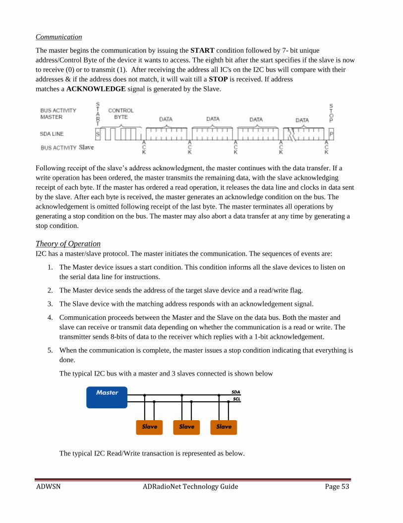
ADWSN ADRadioNet Technology Guide Page 53
Communication
The master begins the communication by issuing the START condition followed by 7- bit unique
address/Control Byte of the device it wants to access. The eighth bit after the start specifies if the slave is now
to receive (0) or to transmit (1). After receiving the address all IC's on the I2C bus will compare with their
addresses & if the address does not match, it will wait till a STOP is received. If address
matches a ACKNOWLEDGE signal is generated by the Slave.
Following receipt of the slave’s address acknowledgment, the master continues with the data transfer. If a
write operation has been ordered, the master transmits the remaining data, with the slave acknowledging
receipt of each byte. If the master has ordered a read operation, it releases the data line and clocks in data sent
by the slave. After each byte is received, the master generates an acknowledge condition on the bus. The
acknowledgement is omitted following receipt of the last byte. The master terminates all operations by
generating a stop condition on the bus. The master may also abort a data transfer at any time by generating a
stop condition.
Theory of Operation
I2C has a master/slave protocol. The master initiates the communication. The sequences of events are:
1. The Master device issues a start condition. This condition informs all the slave devices to listen on
the serial data line for instructions.
2. The Master device sends the address of the target slave device and a read/write flag.
3. The Slave device with the matching address responds with an acknowledgement signal.
4. Communication proceeds between the Master and the Slave on the data bus. Both the master and
slave can receive or transmit data depending on whether the communication is a read or write. The
transmitter sends 8-bits of data to the receiver which replies with a 1-bit acknowledgement.
5. When the communication is complete, the master issues a stop condition indicating that everything is
done.
The typical I2C bus with a master and 3 slaves connected is shown below
The typical I2C Read/Write transaction is represented as below.

ADWSN ADRadioNet Technology Guide Page 54
ADT75 Sensor Interface
ADT75 is 12-bit Digital temperature Sensor. It has I2C compatible interface for reading temperature data and
writing configuration to registers. It operates in two modes to perform measurement as continuous conversion
and one-shot mode. In continuous mode the device will measure the temperature for every 100 milliseconds.
In one-shot mode, the device will be in low power mode until write happens to ONESHOTMODE register,
then it starts measuring the data on and the data will be available in Temperature value register (0x00) after 60
milliseconds. One shot mode is best suited for Wireless Sensor Application as we need to save power as much
as possible.
Enabling Interrupt on critical temperature barriers
ADT75 has an output pin which can be used to generate critical temperature indication. If the device operated
in Comparator mode, this pin will be SET once the temperature crosses Over-Temperature reading (written to
TOS) and will RESET only when the temperature falls below the Hysteresis temperature reading (written to
THYST). This mode is useful for polling this pin in software, in case of the micro-controller can’t accommodate
interrupt source.
Other mode is Interrupt mode, in which this pin will be SET once the temperature, crosses Over-Temperature
reading (written to TOS) and will RESET when the data is read by the application. Also SETs when the
temperature falls below the Hysteresis temperature reading (written to THYST) and will RESET when the data
is read by the application. This mode is useful in Wireless Sensor application.
So the device is configured as One Shot+ Interrupt mode by setting D5 & D1 bits of Configuration Register
(0x01). Also the Barriers for Interrupt generation are configured by writing Over-Temperature Limit to TOS
(0x03) register and Hysteresis temperature limit to THYST (0x02). MSB represents the sign and the value is
calculated by dividing the read out value by 16. The device address for I2C access is 0x4F
Datasheet: http://www.analog.com/static/imported-files/data_sheets/ADT75.pdf
API’s for reference
ADI_SENSOR_RESULT_TYPE ADT75_Init() //Configures and Initializes ADT75
Get_Temp_From_ADT75() //Reads Temperature data from ADT75
Power Consumption:
If the device is operated in Continuous Conversion mode, it consumes about 200µA. To save power we are
operating the in one shot mode, in which sensor consumes 200µA only when user reads the temperature and
other time it will be in Power Down mode where it consumes ~3 µA only. This is verified practically.
ADXL345 Sensor Interface
The ADXL345 is a small, thin, ultralow power, 3-axis accelerometer with high resolution (13-bit)
measurement at up to ±16g. Digital output data is formatted as 16-bit twos complement and is
accessible through either a SPI (3- or 4-wire) or I2C digital interface. We use I2C incurrent
implementation. It converts the acceleration to g and shows in digital form.

ADWSN ADRadioNet Technology Guide Page 55
The device address for I2C access is 0x1D
In normal mode the device starts converting the data at the data rate set by RATE (bits D3:D0 of BW_RATE
register, 0x2C). It consumes about 140µA in this mode for above 100Hz rate.
Datasheet: http://www.analog.com/static/imported-files/data_sheets/ADXL345.pdf
We operate it in Low Power Mode, by setting Low Power bit (bit D4 of BW_RATE register), which makes the
device to consume ~35µA.
API’s for reference
ADI_SENSOR_RESULT_TYPE ADXL345_Init() //Configures and Initializes ADXL345
Get_Temp_From_ADXL345() //Reads Temperature data from ADXL345 and updates the value in
Global //data structure
AD7151 Sensor Interface
The AD7151 delivers a complete signal processing solution for capacitive proximity sensors, featuring an ultra-
low power converter with fast response time. In our application it is used for touch detection which can be used
as contact-less switch or touch switch by measuring the capacitance in idle time and when the device is touched.
It has several modes of operation supported as Power down, Continuous conversion and Single Conversion.
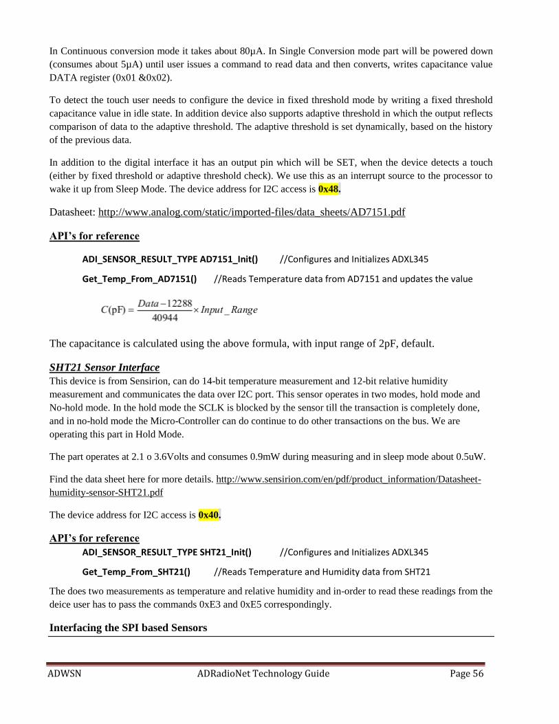
ADWSN ADRadioNet Technology Guide Page 56
In Continuous conversion mode it takes about 80µA. In Single Conversion mode part will be powered down
(consumes about 5µA) until user issues a command to read data and then converts, writes capacitance value
DATA register (0x01 &0x02).
To detect the touch user needs to configure the device in fixed threshold mode by writing a fixed threshold
capacitance value in idle state. In addition device also supports adaptive threshold in which the output reflects
comparison of data to the adaptive threshold. The adaptive threshold is set dynamically, based on the history
of the previous data.
In addition to the digital interface it has an output pin which will be SET, when the device detects a touch
(either by fixed threshold or adaptive threshold check). We use this as an interrupt source to the processor to
wake it up from Sleep Mode. The device address for I2C access is 0x48.
Datasheet: http://www.analog.com/static/imported-files/data_sheets/AD7151.pdf
API’s for reference
ADI_SENSOR_RESULT_TYPE AD7151_Init() //Configures and Initializes ADXL345
Get_Temp_From_AD7151() //Reads Temperature data from AD7151 and updates the value
The capacitance is calculated using the above formula, with input range of 2pF, default.
SHT21 Sensor Interface
This device is from Sensirion, can do 14-bit temperature measurement and 12-bit relative humidity
measurement and communicates the data over I2C port. This sensor operates in two modes, hold mode and
No-hold mode. In the hold mode the SCLK is blocked by the sensor till the transaction is completely done,
and in no-hold mode the Micro-Controller can do continue to do other transactions on the bus. We are
operating this part in Hold Mode.
The part operates at 2.1 o 3.6Volts and consumes 0.9mW during measuring and in sleep mode about 0.5uW.
Find the data sheet here for more details. http://www.sensirion.com/en/pdf/product_information/Datasheet-
humidity-sensor-SHT21.pdf
The device address for I2C access is 0x40.
API’s for reference
ADI_SENSOR_RESULT_TYPE SHT21_Init() //Configures and Initializes ADXL345
Get_Temp_From_SHT21() //Reads Temperature and Humidity data from SHT21
The does two measurements as temperature and relative humidity and in-order to read these readings from the
deice user has to pass the commands 0xE3 and 0xE5 correspondingly.
Interfacing the SPI based Sensors
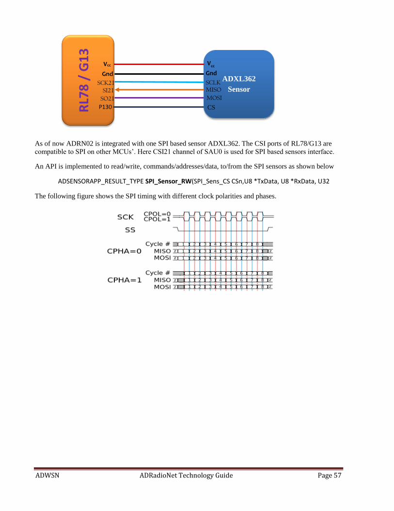
ADWSN ADRadioNet Technology Guide Page 57
As of now ADRN02 is integrated with one SPI based sensor ADXL362. The CSI ports of RL78/G13 are
compatible to SPI on other MCUs’. Here CSI21 channel of SAU0 is used for SPI based sensors interface.
An API is implemented to read/write, commands/addresses/data, to/from the SPI sensors as shown below
ADSENSORAPP_RESULT_TYPE SPI_Sensor_RW(SPI_Sens_CS CSn,U8 *TxData, U8 *RxData, U32
The following figure shows the SPI timing with different clock polarities and phases.
ADXL362
Sensor R
L78
/ G
13
Vcc
Gnd
SCK21 SI21
SO21
P130
Vcc
Gnd
SCLK MISO MOSI
CS
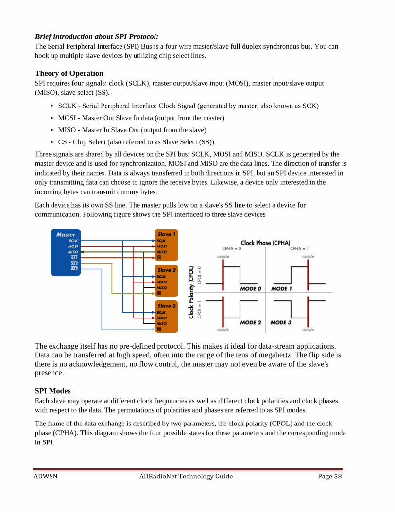
ADWSN ADRadioNet Technology Guide Page 58
Brief introduction about SPI Protocol:
The Serial Peripheral Interface (SPI) Bus is a four wire master/slave full duplex synchronous bus. You can
hook up multiple slave devices by utilizing chip select lines.
Theory of Operation
SPI requires four signals: clock (SCLK), master output/slave input (MOSI), master input/slave output
(MISO), slave select (SS).
SCLK - Serial Peripheral Interface Clock Signal (generated by master, also known as SCK)
MOSI - Master Out Slave In data (output from the master)
MISO - Master In Slave Out (output from the slave)
CS - Chip Select (also referred to as Slave Select (SS))
Three signals are shared by all devices on the SPI bus: SCLK, MOSI and MISO. SCLK is generated by the
master device and is used for synchronization. MOSI and MISO are the data lines. The direction of transfer is
indicated by their names. Data is always transferred in both directions in SPI, but an SPI device interested in
only transmitting data can choose to ignore the receive bytes. Likewise, a device only interested in the
incoming bytes can transmit dummy bytes.
Each device has its own SS line. The master pulls low on a slave's SS line to select a device for
communication. Following figure shows the SPI interfaced to three slave devices
The exchange itself has no pre-defined protocol. This makes it ideal for data-stream applications.
Data can be transferred at high speed, often into the range of the tens of megahertz. The flip side is
there is no acknowledgement, no flow control, the master may not even be aware of the slave's
presence.
SPI Modes
Each slave may operate at different clock frequencies as well as different clock polarities and clock phases
with respect to the data. The permutations of polarities and phases are referred to as SPI modes.
The frame of the data exchange is described by two parameters, the clock polarity (CPOL) and the clock
phase (CPHA). This diagram shows the four possible states for these parameters and the corresponding mode
in SPI.

ADWSN ADRadioNet Technology Guide Page 59
ADXL362 Sensor Interface
The ADXL362 is a complete 3-axis MEMS acceleration measurement system that operates at extremely low
power consumption levels. It measures both dynamic acceleration, resulting from motion or shock, and static
acceleration, such as tilt. Acceleration is reported digitally and the device communicates via the SPI protocol.
Built-in digital logic enables autonomous operation and implements functionality that enhances system level
power savings. It consumes less than 2 µA at a 100 Hz output data rate and 270nA when in motion triggered
wake-up mode. The ADXL362 always provides 12-bit output resolution; 8-bit formatted data is also provided
for more efficient single-byte transfers when a lower resolution is sufficient. Measurement ranges of ±2g, ±4g,
and ±8 g are available, with a resolution of 1 mg/LSB on the ±2 g range. In addition to its ultralow power
consumption, the ADXL362 has many features to enable true system level power reduction.
It has two operating modes: measurement mode for continuous, wide bandwidth sensing; and wake-up mode
for limited bandwidth activity detection. In addition, measurement can be suspended altogether by placing the
device in standby.
The ADXL362 is a small, thin, ultralow power, 3-axis accelerometer with high resolution (13-bit) measurement
at up to ±16g. Digital output data is formatted as 16-bit twos complement and is accessible through either a SPI
(3- or 4-wire) or I2C digital interface. We use I2C incurrent implementation. It converts the acceleration to g
and shows in digital form.
This sensor is mounted on TinyWSN board with the slave select as SS0.
We operate the sensor in Measurement mode by writing bits [D1:0] of PWR_CTRL (0x2D) register as 0x02.
The Output data rate is selected as 12.5Hz by writing bits [D2:0] of the FILTER_CTRL (0x2C) as 0x00 and
range is selected as ±2g by writing bits [D7:6] of the FILTER_CTRL (0x2C) as 0x00.
Datasheet: http://www.analog.com/static/imported-files/data_sheets/ADXL362.pdf
API’s for reference
ADI_SENSOR_RESULT_TYPE ADXL362_Init() //Configures and Initializes ADXL362
Get_Data_From_ADXL362() //Reads Temperature data from ADXL362 and updates the value
//in Global data structure

ADWSN ADRadioNet Technology Guide Page 60
Interfacing the ADC based Sensors
RL78/G13 has 10/8-bit ADC which supports up to 12 single-ended channels.
ALS Sensor (APDS-9005) Interface:
Avago’s APDS-9005, a miniature surface-mount ambient light photo sensor is interface to ADC
channel-1. This channel is initialized as part of ADSensMain(); sequence. Power supply ranges
from 3.2V to 5V.
The conversion will start when ADC is enabled on a particular channel and the 10-bit output will be
updated in ADCR [15:6 bits] register. An API ADC_Get_Result (); is provided in drivers is being
used here to do the conversion and returns the contents of ADCR register to destination buffer. Later
the data right shifted be 6 bits and update to global sensor data structure.
Datasheet: http://www.avagotech.com/docs/AV02-0080EN


