Embed Size (px)
Citation preview

A E l ti b d D iAn Evolutionary based Dynamic Energy Management Framework forEnergy Management Framework for
IP-over-DWDM Core Networks
Xin Chen, Chris PhillipsSchool of Electronic Engineering &
C t S iComputer Science
O tliOutline
Introductionk dBackground
New Energy Management DesignNew Energy Management DesignSimulationFurther work
2

IntroductionIntroduction
Benefits of Energy SavingEconomical
Lower OPEX for ISPsLower OPEX for ISPsEnvironmental
Lower CO2 emissions
3

d iIntroduction
Our energy management scheme combines gy ginfrastructure sleeping and virtual router migration together with automatic opticalmigration together with automatic optical layer connection forwarding to enable resources to be used in an energy efficientresources to be used in an energy-efficient manner.
4
k dBackground
Network ArchitectureNetwork Architecture Energy Saving ApproachesInfrastructure sleeping and Virtual Router Migration TechniquesRouter Migration Techniques
5
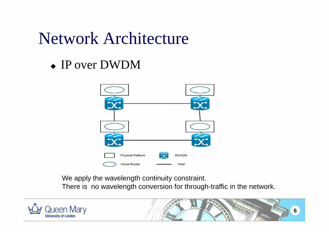
Network ArchitectureIP over DWDM
Network ArchitectureIP over DWDM
We apply the wavelength continuity constraint. There is no wavelength conversion for through-traffic in the network.
6

S i A hEnergy Saving Approaches
Static MechanismsStatic MechanismsNetwork planning, i.e. ILP
Dynamic Mechanismsf l i d iInfrastructure sleeping, rate adaptation,
network virtualization…..
7

Infrastructure Sleepingp gSwitch off unneeded equipment during off-peak periodsperiodsPrevious work [over 20% saving]
L. Chiaraviglio, M. Mellia, and F. Neri, "Energy-Aware Backbone Networks: A Case Study" in IEEE International Conference on Communications Workshops, 2009, pp. 1–5, June 2009.
8

f Sl iInfrastructure Sleeping
Some issues and limitationsSome issues and limitations
The problem of loss of connectivity due p yto reconvergenceWhen to sleep / wake ?When to sleep / wake ?How to sleep / wake ?
9

Virtual Router MigrationgMove virtual routers among difference physical platform
i h d di h iwithout degrading the service
Wang, Yi,; Keller, E.; Biskeborn, B.; Jacobus van der Merwe, Rexford, J.; ,"Virtual routers on the move: live router migration as a network-management primitive," SIGCOMM Comput. Commun. Rev. 38, 4 (August 2008), 231-242.
10

i l i iVirtual Router Migration
Some issues and limitations
When to trigger virtual router migration?When to trigger virtual router migration?Where to move virtual routers to?
11

Dynamic Energy ManagementDynamic Energy Management Framework
Overall Energy Management Procedure
Optical Connection Management
VRM_MOEAVirtual Router Migration – Multi-Objective Evolutionary Algorithm
12

Overall Energy Management ProcedureOverall Energy Management Procedure
1 C ll t d l th t k t t1. Collect and analyze the network status
2. Trigger VRM MOEA. (Quiet and Busy Thresholds)gg _ (Q y )
3. Establish the new optical connections
4. Virtual router migration5 Then Switch off (on) the corresponding physical5. Then Switch off (on) the corresponding physical
platforms and removed the unneeded optical connectionsconnections
6. Go back to step 1 to recheck the network status
13

Dynamic Optical Connection ManagementAdditi l ti l ti d d fAdditional optical connections are needed for forwarding the traffic to the remote virtual
t ( ) i th k trouter(s) processing the packets
Changes in the underlying physical network are hidden from the topology as seen by Layer-3 and p gy y yso reconvergence events are avoided
14
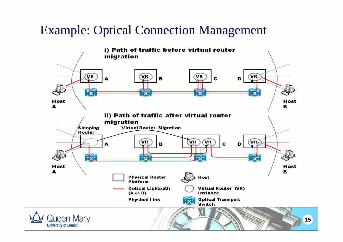
Example: Optical Connection Management
15

Destination Physical Platform Selection yAlgorithm- VRM_MOEA
Individual chromosome representation:
Gene VR index
Chromosome length set to sum of VRs
2Gene, VR index
Allele gives PP location211
16

Destination Physical Platform Selection yAlgorithm - VRM_MOEA
Initial Population: Pre screening procedure for selecting the variable solutions
Evolutionary algorithm well-suited to real-time operation as search can be halted at any point and we only need a “good”and we only need a good solution
17

Destination Physical Platform Selection yAlgorithm- VRM_MOEA
T bj ti f tiTwo objective functions: 1. Power Consumption:
α
1-total base i lc base roadm
iP P N P P P
α
α θ β α β=
= ⋅ + ⋅ + ⋅ ⋅ + ⋅∑ ( )
On PPs On PP Linecards Off PPs On ROADMsto ta lP
P
αβ
----- The power consumption of the network
----- The number of active PPs----- The number of ROADM in the
On PPs On PP Linecards Off PPs On ROADMs
b a seP
lcP θ----- The power consumption of base system----- The power consumption of
network----- A percentage of the base system power consumption a PP consumes
h i i l iro a d mP
iNa line card----- The power consumption of a ROADM
when it is sleeping.----- The number of active line cards in the i-th PP
18

Destination Physical Platform Selection Al ith VRM MOEAAlgorithm- VRM_MOEA
2. Virtual Router Migration Cost (Second objective function)
The first VRM cost component comes from hop count f i i l “h ” VR l ti t it d ti ti PPfrom an original “home” VR location to its destination PP. For i-th candidate solution:
β
01
_ ( ) ( , )j ji
j
Cost a i d g gβ
=
= ∑
0ig
----- A function for obtaining the distance between two PPs: x1 and x2. ----- j-th gene in the default network configuration
( 1, 2 )d x x
jig
β
----- j-th gene in a candidate solution.
----- The number of VR
19

Destination Physical Platform Selection Al ith VRM MOEAAlgorithm- VRM_MOEA
The second component comes from the virtual routerThe second component comes from the virtual router migration process
β
1_ ( ) ( , )j j
current ij
Cost b i d g gβ
=
=∑ic u rren tg ----- j -th gene in the current network
Therefore The overall cost of one possible solution
c u rren tg
jig
j gconfiguration----- j-th gene in a candidate solution.
Therefore, The overall cost of one possible solution is :
( ) ( ) (1- ) ( )Cost i Cost a i Cost b iϕ ϕ= ⋅ + ⋅( ) _ ( ) ( ) _ ( )ϕ ϕ
ϕ ----- Weight of two cost terms
20

Destination Physical Platform Selection yAlgorithm- VRM_MOEA
Fi f iFitness function:
Strength Pareto Evolutionary Algorithm II (SPEA2)
Selection Mechanism:
To rn ment sele tionTournament selection
Crossover Operation:
BLX-α crossover
Mutation Operation:Mutation Operation:
Mutation rate = 0.1
21

Strength Pareto Evolutionary Algorithm II (SP A2)II (SPEA2)
The relationship between two decision vectors : Dominance , indifferenceThe relationship between two decision vectors : Dominance , indifference
22

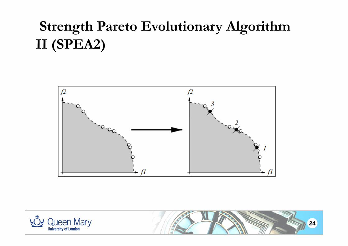
Strength Pareto Evolutionary Algorithm II (SP A2)II (SPEA2)
SPEA2 P dSPEA2 Procedure:
1.Assign a strength score to each solution. The score is equal to the number of
solutions it dominates.
2.Get the raw fitness value of a solution by summing up the strength score of
solutions which dominate it.
3.Get the density value by K-th nearest neighbor method (K=1).
4.Add the raw fitness value and density value to obtain the fitness value. A non-
dominate solution has fitness value 0.
23
Strength Pareto Evolutionary Algorithm II (SP A2)II (SPEA2)
24

BLX-α CrossoverBLX α CrossoverIt offers an opportunity that after crossover, the offspring’s genes come pp y p g gfrom a slightly larger range randomly selected between the two parents’ genes.
Procedure:Procedure:For two Parets: G1, G2, the i-th gene of offspring is define:
[ ]h Uniform g I g Iα α= − ⋅ + ⋅
ih
min max[ , ]ih Uniform g I g Iα α= − ⋅ + ⋅1 2
min ( , )i ig Min g g=1 2 11 2
max ( , )i ig Max g g=
max minI g g= −
1ig2ig
----- i-th gene of G1----- i-th gene of G2----- An user define parameterα
25

Simulation
Simulator IntroductionSimulation Results
26

Simulator Introduction 1. Main simulation framework: Hybrid simulator
2. Network topology: a simple network topology generatorp gy p p gy g
3. Traffic model: fluid flow model and daily traffic model
4 D i i h i l l f l i bl4. Destination physical platform selection problem:
VRM_MOEA
5. When to trigger VRM : Reactive mechanism
27

Simulation Results Network 6N8L 11N14L
Scheme Name Energy Energy Energy Energy
Consumption / day Saving Consumption / day Saving
No VRM 4057200.00 0.00% 7698240.00 0.00%
Quick VRM 3223327.20 20.55% 6008048.00 21.96%
VRM_MOEA(0 ,1) 3134507.20 22.74% 5457832.20 29.10%
VRM_MOEA(0.2,0.8) 3125365.00 22.97% 5451220.20 29.97%
VRM_MOEA(0.5,0.5) 3140139.80 22.60% 5471056.80 28.93%
VRM_MOEA(0.8,0.2) 3160408.40 22.10% 5490892.40 28.67%
VRM_MOEA(1 ,0) 3144768.20 22.49% 5517340.00 28.33%
A l 5 i l ti ith d dAverage values over 5 simulations with random seeds
Quick VRM chooses the best solution in a randomly generated population of candidate solutions without any evolutionary process
28
y y

Simulation ResultsSimulation Results
The optical infrastructure
The energy saving is similar among the different VRM_MOEA schemes
is “always on”
In the off-peak hours, e.g. 12 to 24, the energy saving performance of VRM_MOEA is better than Quick VRM
29

Simulation Results
Per fibre, there are 40 channels each operating at ope a g a40Gb/s The PP switch fabric can accommodate 1Tb/s traffic load
The occupied number of lightpaths fluctuate with the traffic load in the baseline schemescheme.
When VRs are moved to remote PPs , more optical channels are used for transmitting the packets to be processed by VRs than that of the baseline case.
The discontinuities on the lines correspond to virtual router migrations.
30
The discontinuities on the lines correspond to virtual router migrations.

Simulation ResultsSimulation Results
Higher quiet and busy thresholds cause a higher energy saving.g q y g gy g
31

Simulation ResultsSimulation Results 60
1 γ⎡ ⎤
50
60
)
It is more difficult to gain
1-( ) (1 sin( ))2
ij ijT t f tγδ γ⎡ ⎤= Α ⋅ + ⋅ +⎢ ⎥⎣ ⎦40
30
y Sa
ving
(%)
gthe energy saving in a busier network.20
10
Ener
gy
10
32

Future WorkFuture Work
1. Reactive mechanism Short term proactive mechanism
2 Add the VRM migration time into the simulation2. Add the VRM migration time into the simulation
33

Thank you!Thank you!
34