Embed Size (px)
Citation preview

© 2019 Emerson
1
Application Guidelines for Copeland™ AF, AR & AS Refrigeration Hermetic Compressors
For Refrigerants R-22, R-134A, R-404A, R-507, R-290, R-450A, R-513A, R-448A, R-449A TABLE OF CONTENTS Safety Instructions ....................................................... 3 Safety Icon Explanation ............................................... 3 Instructions Pertaining to Risk of Electrical Shock, Fire, or Injury to Persons ...................................................... 4 Safety Statements ........................................................ 4 1. Introduction .................................................. 5 2. Nomenclature ............................................... 5 3. Operating Envelope ..................................... 5 4. Superheat Requirements ............................. 5 5. Suction Accumulator .................................... 6 6. Discharge Line Check Valve ........................ 6 7. Crankcase Heaters ...................................... 6 8. Lubricants ..................................................... 6 9. Practical Considerations .............................. 6 10. Use of R-450A and R-513A Refrigerants .... 7 11. Use of R290 / General Information .............. 7 12. Starting Characteristics ................................ 7 13. Application Instructions ................................ 8 14. Deep Vacuum Operation ............................. 8 15. High Potential (Hipot) Testing ...................... 8 16. Electrical Connections ................................. 8 17. Positive Temperature Coefficient (PTC) Starter .......................................................... 8 17.1. PTC Performance ........................................ 8 17.2. Application Notes ......................................... 9 17.3. PTCR Dimensional Drawing ........................ 9 18. Mounting ...................................................... 9
FIGURES Figure 1 - A*E Nomenclature ..................................... 10 Figure 2 Split Phase Motor Connection ..................... 11 Figure 3 Capacitor Start – Capacitor Run Motor Connection ................................................................. 11 Figure 4 Capacitor Start – Induction Run Motor ......... 11 Figure 5 Permanent Split Capacitor Motor with PTC Start Assist Connection .............................................. 11 Figure 6 - Mounting Kit 527-C001-00 ......................... 12 Figure 7 - Mounting Kit 527-C001-02 ......................... 12 Figure 8 A*E**C5E ..................................................... 13 Figure 9 AFF**C1E ..................................................... 13 Figure 10 ASM**C1U.................................................. 13 Figure 11 - R-404A / R-507 / R-290* EXT. MED TEMP. .................................................................................... 14 Figure 12 - R-404A / R-449A / R-448A / R-507 / R-290* - MED TEMP. ............................................................ 14 Figure 13 - R-448A / R-449A – LOW TEMP .............. 14 Figure 14 - R-290 Extended Medium Temp ............... 14 Figure 15 - R-134a / R-450A / R-513A – EXT. MED TEMP .......................................................................... 15 Figure 16 - R-134a / R-450A / R-513A – HIGH TEMP .................................................................................... 15 Figure 17 - R-22 – MED TEMP .................................. 15 Figure 18 - R-22 – HIGH TEMP ................................. 15 Figure 19 - R-134a / R-290 / R-450A / R-513A – EXT. MED TEMP ................................................................. 16
TABLES Table 1 - Approved Refrigerants/Lubricants .............. 16 Table 2 - Low Pressure Control Settings ................... 17 Table 3 - Refrigerant Charge Limits ........................... 17 Table 4 - Mounting Kits .............................................. 18 Table 5 - DLT Controls ............................................... 18
AE4-1305 R23 September 2019
© 2019 Emerson
2
AE4-1305 R23
Revision Tracking R23 (September 2019)
Pg. 6 – Section 5 : Recommended Check valve position
changed to be closer to the compressor.
Revision Tracking R22 (September 2018)
Pg. 6 – POE oil warning label updated. Pg. 16 – Table 1: “Approved Refrigerants/Lubricants” updated. Pg. 7 – Section 10 “Use of R-450A and R-513A Refrigerants”. Crankcase heater was changed from mandatory to recommended. Pg. 14 – Maximum Return Gas requirement corrected to 40°F for Med. Temp. Applications for R-404A / R-449A / R-448A / R-507 / R-290*. Pg.15 – Maximum Return Gas requirement corrected to 40°F for Ext. Medium Temp. for R-134a / R-450A / R-513A.
Revision Tracking R21 (September 2017)
Pg. 6 – ASM low Torque Starting Characteristics Pg. 6 – Use of R290 General Information Pg. 7 – PTC Device Information
Pg. 8 – Updated Nomenclature Description.
Pg. 12 – ASM cut-away drawing
Pg. 13 – ASM Extended Medium Temp R290 Envelope
Pg. 15 – Updated Approved Refrigerants Table
Pg. 16 – AS(M) and R290 low pressure cut out settings

© 2019 Emerson
3
AE4-1305 R23
Safety Instructions
Copeland™ compressors are manufactured according to the latest U.S. and European Safety Standards. Particular emphasis has been placed on the user's safety. Safety icons are explained below and safety instructions applicable to the products in this bulletin are grouped on Page 3. These instructions should be retained throughout the lifetime of the compressor. You are strongly advised to follow these safety instructions.
Safety Icon Explanation
DANGER indicates a hazardous situation which, if not avoided, will result in death or serious injury. WARNING indicates a hazardous situation which, if not avoided, could result in death or serious injury. CAUTION, used with the safety alert symbol, indicates a hazardous situation which, if not avoided, could result in minor or moderate injury.
NOTICE is used to address practices not related to personal injury.
CAUTION, without the safety alert symbol, is used to address practices not related to personal injury. FLAMMABLE
DANGER
WARNING
CAUTION
NOTICE
CAUTION

© 2019 Emerson
4
AE4-1305 R23
Instructions Pertaining to Risk of Electrical Shock, Fire, or Injury to Persons
WARNING ELECTRICAL SHOCK HAZARD
• Disconnect and lock out power before servicing.
• Discharge all capacitors before servicing.
• Use compressor with grounded system only.
• Molded electrical plug must be used when required.
• Refer to original equipment wiring diagrams.
• Electrical connections must be made by qualified electrical personnel.
• Failure to follow these warnings could result in serious personal injury.
PRESSURIZED SYSTEM HAZARD
• System contains refrigerant and oil under pressure.
• Remove refrigerant from both the high and low compressor side before removing compressor.
• Never install a system and leave it unattended when it has no charge, a holding charge, or with the service valves closed without electrically locking out the system.
• Use only approved refrigerants and refrigeration oils.
• Personal safety equipment must be used.
• Failure to follow these warnings could result in serious personal injury.
BURN HAZARD
• Do not touch the compressor until it has cooled down.
• Ensure that materials and wiring do not touch high temperature areas of the compressor.
• Use caution when brazing system components.
• Personal safety equipment must be used.
• Failure to follow these warnings could result in serious personal injury or property damage.
CAUTION COMPRESSOR HANDLING
• Use the appropriate lifting devices to move compressors.
• Personal safety equipment must be used.
• Failure to follow these warnings could result in personal injury or property damage.
Safety Statements
• Refrigerant compressors must be employed only for their intended use.
• Only qualified and authorized HVAC or refrigeration personnel are permitted to install commission and maintain this equipment.
• Electrical connections must be made by qualified electrical personnel.
• All valid standards and codes for installing, servicing, and maintaining electrical and refrigeration equipment must be observed.
WARNING
WARNING
© 2019 Emerson
5
AE4-1305 R23
1. Introduction
Hermetic compressors have been developed for the 1/8
hp to 1 hp refrigeration applications. These compressors
are designed to operate safely and reliably in the high,
medium and extended medium temperature ranges. In
addition, some of the extended medium temperature
compressors have the ability to operate in the low
temperature range with SPECIAL APPLICATION
ENGINEERING APPROVAL. It must be noted however,
that under low evaporating conditions the operating
envelope for these models is restricted.
2. Nomenclature
The HFC/HFO compressor model numbers include the
nominal capacity at the standard ARI 60Hz rating
conditions. The HCFC models still refer to the nominal
horsepower, (hp). Please refer to product literature for
specific model number details. See Figure 1 (page 10).
3. Operating Envelope
There are several refrigerants that have been approved
for use with the A family of compressors, see Table 1
page 16. These models are intended for refrigeration
type duty. The approved operating envelopes are
depicted in Figure 11 through Figure 19 (pages 14-16).
Published performance tables and coefficients will only
contain data to 90ºF condensing temperature.
However, the compressors are approved to operate to
70°F condensing.
The envelopes are defined by the following compressor
limitations:
• Discharge line temperature 225°F
• Discharge valve backer 275°F
• Oil sump 200°F
• Motor windings 275°F
If the system design is such that operation within these
guidelines cannot be guaranteed, then the following
additional controls must be added:
1. Discharge line thermostat – Located 6" from the
compressor and set to cut-out the compressor
at 225°F maximum.
2. Low pressure control – Refer to Table 2 (page
17) for recommended low pressure cut-out
settings based on the various refrigerants.
Note: For additional data on the proper use of R-290,
please reference Application Bulletin AE4-1380.
R-290 is flammable and should be handled by
qualified personnel in accordance with appropriate
care for safe use. Emerson Climate Technologies
highly recommends that service personnel use
spark proof tools, anti-static gloves for hand and
anti-static clothes. Avoid the build-up of
electrostatic charge, work in a well ventilated area.
Fire and smoking is forbidden!
There are only a limited number of R-290 compressors
available at this time; the compressor's nomenclature
will be designated with a "U" in the eighth character for
R-290 application. Example: ASE18C4U-IAA
Compressors designed for the use of R-290 will not be
charged with a positive dry air charge but will have a
slight vacuum from the factory.
4. Superheat Requirements
In order to assure that liquid refrigerant does not return
to the compressor during the running cycle, attention
must be given to maintaining proper superheat at the
compressor suction inlet. Emerson recommends a
minimum of 20°F (11°C) superheat, measured on the
suction line 6 inches (152mm) from the suction valve, to
prevent liquid refrigerant flood back.
Another method to determine if liquid refrigerant is
returning to the compressor is to accurately measure
the temperature difference between the compressor oil
crankcase and the suction line. During continuous
operation we recommend that this difference be a
minimum of 50°F (27°C). This ‘crankcase differential
temperature’ requirement supersedes the minimum
suction superheat requirement in the last paragraph. To
measure oil temperature through the compressor shell,
place a thermocouple on the bottom center (not the
side) of the compressor shell and insulate from the
ambient.
During rapid system changes, such as defrost or ice
harvest cycles, this temperature difference may drop
rapidly for a short period of time. When the crankcase
temperature difference falls below the recommended
50°F (27°C), our recommendation is the duration should
not exceed a maximum (continuous) time period of two

© 2019 Emerson
6
AE4-1305 R23
minutes and should not go lower than a 25°F (14°C)
difference.
Contact your Emerson representative regarding any
exceptions to the above requirements.
5. Suction Accumulator
The addition of a suction accumulator can be an
effective method to prevent damage to the compressor
due to continuous flood back. Through extensive
testing, Emerson recommends the use of suction
accumulators if the system refrigerant charge exceeds
the following limits as shown in Table 3 (Pg.17).
6. Discharge Line Check Valve
On pre-charged units that use AF, AR, or AS
compressors with charge levels greater than the charge
limits listed for each model on Table 3 (Pg.17), a check
valve is required in the discharge line close to the
compressor. This will reduce the potential for liquid
refrigerant migrating to the compressor during transport
and storage. The addition of a crankcase heater on pre-
charged units will also assist in forcing any refrigerant
that might have migrated to the compressor sump
during an extended off or storage time. It is
recommended that the crankcase heater be energized
a minimum of 4 hours before initial startup.
7. Crankcase Heaters
Crankcase heaters are recommended on all outdoor
applications or indoor applications below 40°F. A
crankcase heater is also required on any system with
an accumulator. Reference AE22-1182 for liquid
refrigerant control in refrigeration and air conditioning
systems.
8. Lubricants
Compressors that are approved for use with HFC/HFO
refrigerants are charged with polyol ester lubricant
(POE). HFC/HFO refrigerants require the use of a POE
lubricant to provide proper miscibility and lubricity. The
model nomenclature denotes if the compressor is
charged with a POE lubricant. If the eighth character in
the model nomenclature is the letter 'E' then the
compressor is charged with a POE lubricant, example
AFE13C4E-IAA.
R-22 models are supplied with alkylbenzene oil. The
Alkylbenzene models will not have the 'E' designation
for oil in the nomenclature. example: AFE13C-IAA
POE may cause an allergic skin reaction and must
be handled carefully and the proper protective
equipment (gloves, eye protection, etc.) must be
used when handling POE lubricant. POE must not
come into contact with any surface or material that
might be harmed by POE, including without
limitation, certain polymers (e.g. PVC/ CPVC and
polycarbonate). Refer to the Safety Data Sheet
(SDS) for further details.
In the event lubricant needs to be added to the
system, the proper approved lubricant must be used.
See Table 1 (pg. 16) or reference Form 93-11,
Refrigerants/Lubricants Approved for Use in
Copeland™ Compressors, for a complete list of
approved lubricants. The compressor recharge is 2
oz. less than the oil charge listed on the nameplate.
9. Practical Considerations
The application restrictions imposed on these models
may require careful system design. Some
considerations for the designer are as follow:
1. Units operating at low evaporator temperatures will
be susceptible to overheating with dirty condensers
and/or restricted air flow. Large condensers (with
low TD’s) should be designed into systems using
these compressors and proper condenser coil
maintenance will be more critical. System Air flow
across the compressor and condenser should be
designed to maintain a Discharge line temperature
(Measured 6 inches from the compressor) below
225°F while functioning within the approve
operating envelope of each compressor. Minimum
suction line pressure drops will be important to
maintain SST limits at the compressor.
2. Traditional superheat settings at the TXVs may be
too high to maintain the return gas temperature
limits specified.
3. Suction lines should be well insulated.
4. Suction to liquid heat exchangers may not be
desirable if return gas temperatures specified are to
be maintained.
WARNING

© 2019 Emerson
7
AE4-1305 R23
5. Minimum suction line pressure drops will be
important to maintain saturated suction temperature
limits at the compressor.
6. AF model compressors are not approved for remote
outdoor applications using R-448A and R-449A.
The AF model compressor may be used for low
temperature indoor, and indoor remote applications
using R-448A and R-449A if the required
compressor superheat settings can be met. To
assist in keeping the compressor cool the following
recommendation should be followed:
• A 220°F discharge line temperature cut out is
required to be applied 6" from the compressor on
the discharge line when applying R-448A and R-
449A refrigerants. Table 5 (page 18). Highly
insulated suction lines from the evaporator to the
compressor may be required to reduce superheat
gains.
• Liquid line to suction line heat exchangers are not
recommended.
10. Use of R-450A and R-513A Refrigerants
Note: Refrigerant migration of R-450A and R-513A into
the compressor crankcase could cause low oil viscosity,
which could lead to compressor damages.
When using R-450A and R-513A it is critical to meet the
following requirements:
• Maintain adequate superheat settings with a
minimum superheat of 20°F at the compressor.
• No liquid refrigerant migration into the compressor
at any time, especially during standstill or during or
after defrost.
• Pump down recommended.
• The use of a crankcase heater is recommended.
• Retrofit to R450A and R513A is only allowed for
compressors which are approved for these
refrigerants.
11. Use of R290 / General Information
R-290 (Propane) refrigerant can be used as a Hydrocarbon refrigerant alternative for traditional HCFC/HFC low or medium temperature applications. R-290 CANNOT be used as a retrofit refrigerant, it is
only to be used in new systems specifically designed for R-290. Before supplying compressors for use with R-290, it is first necessary to perform an evaluation of the risks involved with the use of this refrigerant. The customer should perform a risk assessment to ensure proper knowledge about the handling and use of the R-290 in the refrigerant system (for further information please contact the Emerson Climate Technologies Application Engineering Department). It is recommended that manufacturers of refrigeration systems using flammable refrigerants such as R-290, develop accurate charging, leak testing and system testing methods to guarantee that all necessary safety procedures have been met. Safety standards have been developed for the use of hydrocarbons, including leakage simulation tests and specifications for several electrical components which may encounter leaking refrigerants. The following set of UL and international standards, from the International Electrotechnical Commission, on electrical safety contains rules for the design and testing of appliances operating with flammable refrigerants:
12. Starting Characteristics
The ASM R290 compressor models are all Low Starting Torque by design. Meaning the suction and discharge pressures need to be balanced or within 1 bar (14.5 PSIG) of each other at compressor start up. This can be achieved by either applying a cap tube or a balanced port TXV that can bleed off the pressure prior to start up.
• UL-471 • IEC 60335-2-24: Household refrigerators and freezers • IEC 60335-2-34: Motor compressors • IEC 60335-2-89: Commercial refrigerators and freezers • IEC 60335-2-40: Heat pumps, air conditioners and dehumidifiers
The US Significant New Alternatives Policy (SNAP) The SNAP ruling for hydrocarbon is divided into two components:
Refrigerators and freezers: the charge limitations are 57g (2.0 ounces) in any refrigerator, freezer, or combination refrigerator and freezer. Retail food refrigerator and freezers: the charge limitation for propane R-290 is 150g (5.29 ounces). (For more information, visit http://www.epa.gov/ozone/snap)

© 2019 Emerson
8
AE4-1305 R23
13. Application Instructions
Contact System OEM for specific application instructions. For general compressor guidelines, please reference AE4-1380 (Guide for the Use of R-290 Refrigerant in Copeland™ Refrigeration Compressors) and AE4-1344 (Application Guidelines for RFT, RRT, RST Compressors). Contact Application Engineering for any further
information.
14. Deep Vacuum Operation
Never attempt to start a
compressor while it is in a vacuum; always break
the vacuum with a refrigerant charge before
applying power. Operating a compressor in a deep
vacuum could cause electrical arcing inside the
compressor.
A low pressure control is required for protection against
deep vacuum operation. Refrigerant compressors are
not designed for and should not be used to evacuate a
refrigeration or air conditioning system. See AE24-1105
for proper system evacuation procedures.
15. High Potential (Hipot) Testing
Many of the Copeland brand compressors are
configured with the motor below the compressor. As a
result when liquid refrigerant is within the compressor
shell the motor can be immersed in liquid refrigerant to
a greater extent than with compressors with the motor
mounted above the compressor. When Copeland brand
compressors are Hipot tested and liquid refrigerant is in
the shell, they can show higher levels of leakage current
than compressors with the motor on top because of the
higher electrical conductivity of liquid refrigerant than
refrigerant vapor and oil. This phenomenon can occur
with any compressor when the motor is immersed in
refrigerant. The level of current leakage does not
present any safety issue. To lower the current leakage
reading the system should be operated for a brief period
of time to redistribute the refrigerant to a more normal
configuration and the system Hipot tested again. See
bulletin AE4-1294 for Megaohm testing
recommendations. Under no circumstances should the
Hipot or Megaohm test be performed while the
compressor is under a vacuum.
High Potential (Hipot) Testing/Megaohm Testing
with R-290
Special attention should be taken when using a
Hipot/ Megaohm reading on an R-290 compressor.
These tests can induce an electrical arc and cause
a potential fire/explosion hazard. Compressors
removed from an R-290 system will need to have the
oil drained and a nitrogen purge introduced to flush
any remaining R-290 from the compressor prior to
Hipot /Megaohm testing.
16. Electrical Connections
Only use Emerson Climate Technologies listed start
components for R-290 compressor applications, as
only these components have been tested to and
meet the safety guidelines set forth by UL.
17. Positive Temperature Coefficient (PTC) Starter
The Positive Temperature Coefficient (PTC) Starter is a
low-cost alternative to electro-mechanical relays. The
PTC device mounts directly to the compressor terminal
pins and is fully enclosed within the compressors
terminal box. The motor protector plugs into the
common terminal and the PTC device plugs into the
remaining 2 pins.
17.1. PTC Performance
When power is first applied to the compressor the PTC
is in a low resistances state. Current flows through the

© 2019 Emerson
9
AE4-1305 R23
PTC device to the start winding, causing a beneficial
phase angle shift between the start and main windings,
and resulting in an increase in the starting torque.
Emerson recommends a 5-7-minute off time
between starts to allow for proper cooling of the
PTC device and reliable compressor starting
characteristics.
17.2. Application Notes
1) The surface and the terminals of the PTC device can
reach high temperatures during normal running
conditions. Any material in contact with the PTC device
and its terminals, including wire and connectors should
have a minimum temperature rating of 105°C (221°F).
Adequate spacing should be provided to insulate lower
rated materials from this heat source.
2) The PTC device should be protected from potential
sources of liquid, such as evaporator trays and water
connections.
3) Certain materials such as chlorine (Cl) containing
gasses, can degrade the characteristics of the PTC
device. The PTC device should not be exposed to
Sulphur (S) or Chlorine (Cl) containing gasses, and
must be kept away from materials that can generate
them. In particular, avoid the use of polyvinyl chlorine
(PVC) insulation in contact with the PTC device and its
terminals.
4) The PTC device is designed to be used in conjunction
with a terminal box cover.
17.3. PTCR Dimensional Drawing
Single phase motor connections are shown in Figure 2
through Figure 5 (page 11).
It is recommended that insulated terminal connectors be
used within the compressor's terminal box whenever
possible. Ensure that the terminal connections do not
interfere with the closing of the terminal box cover.
Terminal covers must be installed properly prior to
energizing the compressor.
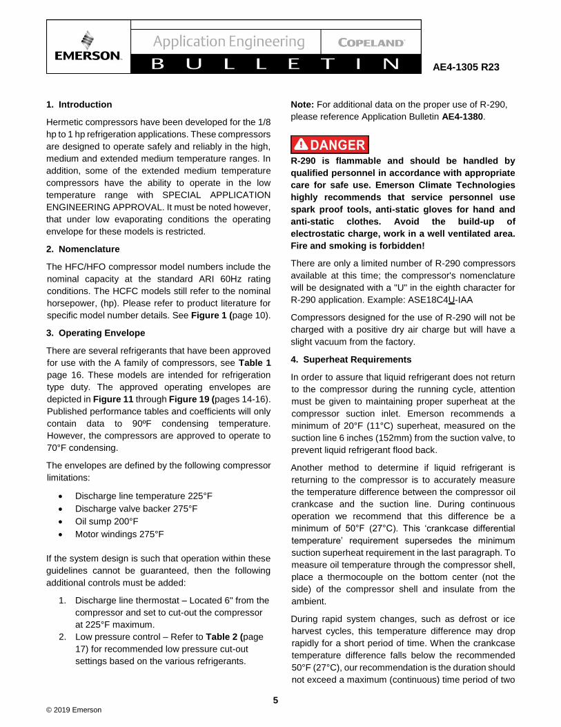
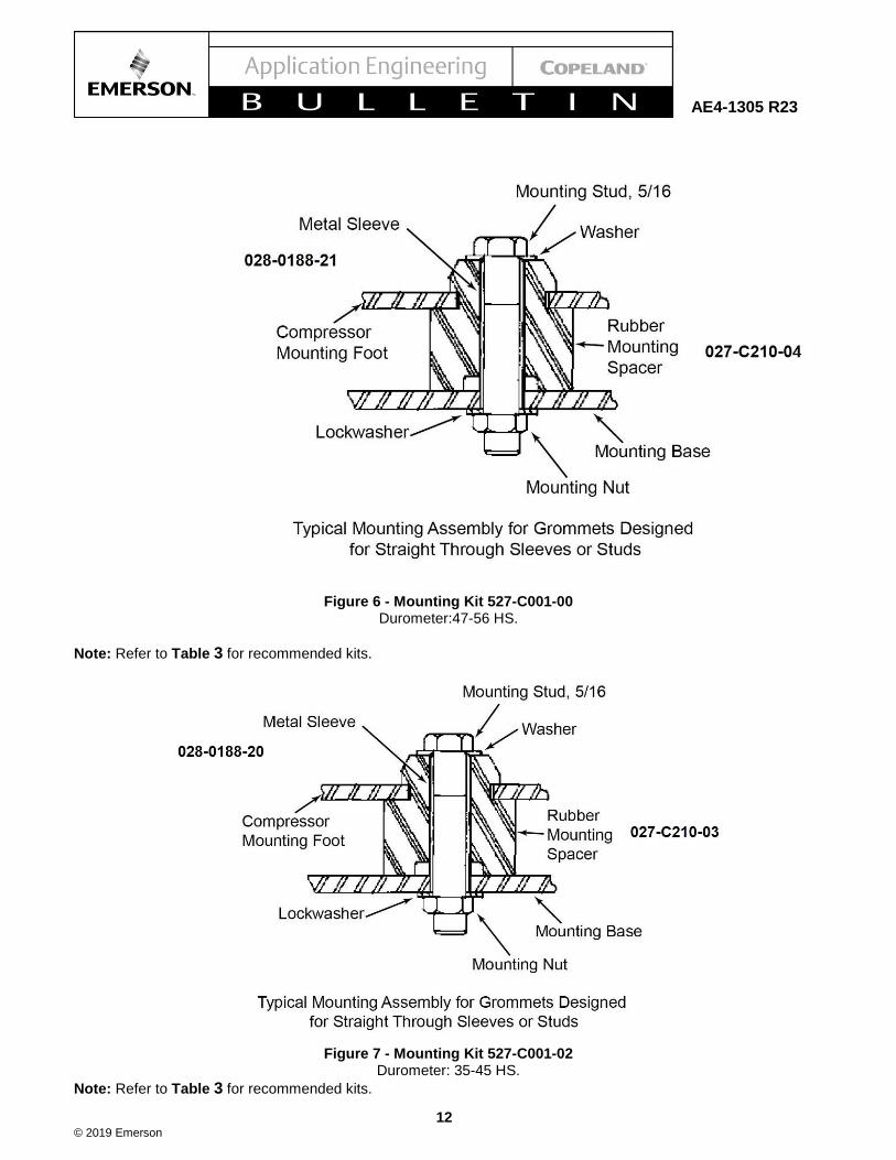
18. Mounting
The AF, AR and AS compressors are internally spring
mounted to reduce vibrations. Resilient type mounts
have been developed specifically for these
compressors. See Table 4 (page 18). Typical mounting
assemblies are shown in Figure 6 and Figure 7 (page
12).

© 2019 Emerson
10
AE4-1305 R23
Figure 1 - A*E Nomenclature

© 2019 Emerson
11
Figure 2 Split Phase Motor Connection
Figure 3 Capacitor Start – Capacitor Run Motor Connection
Figure 4 Capacitor Start – Induction Run Motor
Figure 5 Permanent Split Capacitor Motor with PTC Start Assist Connection
© 2019 Emerson
12
AE4-1305 R23
Figure 6 - Mounting Kit 527-C001-00 Durometer:47-56 HS.
Note: Refer to Table 3 for recommended kits.
Figure 7 - Mounting Kit 527-C001-02 Durometer: 35-45 HS.
Note: Refer to Table 3 for recommended kits.
© 2019 Emerson
13
AE4-1305 R23
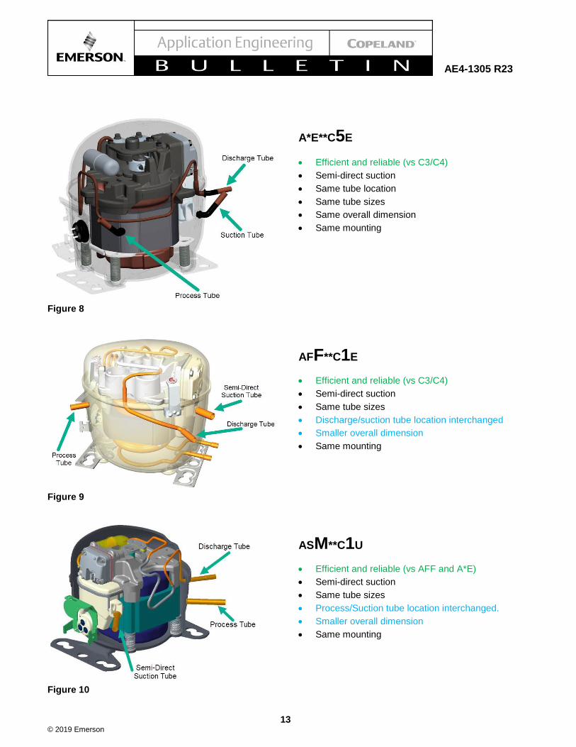
Figure 8 A*E**C5E
A*E**C5E
• Efficient and reliable (vs C3/C4)
• Semi-direct suction
• Same tube location
• Same tube sizes
• Same overall dimension
• Same mounting
Figure 9 AFF**C1E
AFF**C1E
• Efficient and reliable (vs C3/C4)
• Semi-direct suction
• Same tube sizes
• Discharge/suction tube location interchanged
• Smaller overall dimension
• Same mounting
Figure 10 ASM**C1U
ASM**C1U
• Efficient and reliable (vs AFF and A*E)
• Semi-direct suction
• Same tube sizes
• Process/Suction tube location interchanged.
• Smaller overall dimension
• Same mounting

© 2019 Emerson
14
AE4-1305 R23
Figure 11 - R-404A / R-507 / R-290* EXT. MED
TEMP.
Figure 12 - R-404A / R-449A / R-448A / R-507 / R-
290* - MED TEMP.
Figure 13 - R-448A / R-449A – LOW TEMP
Figure 14 - R-290 Extended Medium Temp
Note: See additional restrictions under Practical Considerations, item #6, on page 7 of this document.
*Standard refrigeration compressors cannot be used in R-290 applications under any circumstances!

© 2019 Emerson
15
AE4-1305 R23
Figure 15 - R-134a / R-450A / R-513A – EXT. MED
TEMP
Figure 16 - R-134a / R-450A / R-513A – HIGH TEMP
Figure 17 - R-22 – MED TEMP
Figure 18 - R-22 – HIGH TEMP
*Standard refrigeration compressors cannot be used in R-290 applications under any circumstances!
© 2019 Emerson
16
AE4-1305 R23
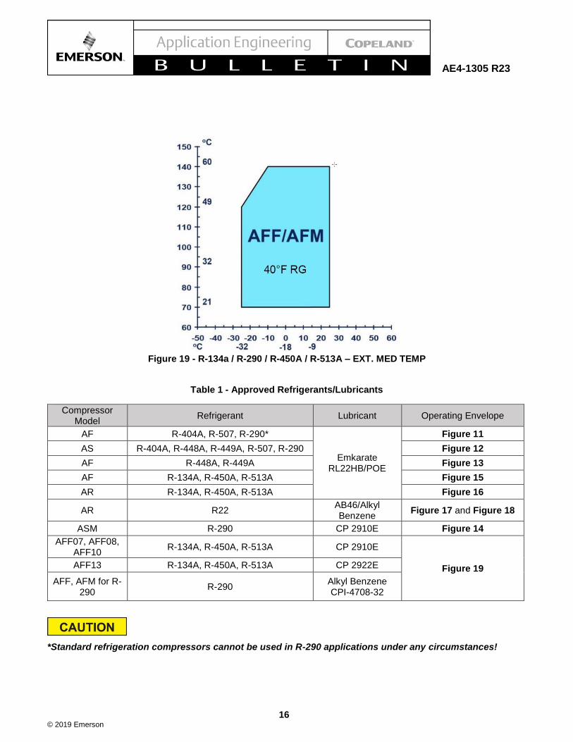
Figure 19 - R-134a / R-290 / R-450A / R-513A – EXT. MED TEMP
Table 1 - Approved Refrigerants/Lubricants
Compressor Model
Refrigerant Lubricant Operating Envelope
AF R-404A, R-507, R-290*
Emkarate RL22HB/POE
Figure 11
AS R-404A, R-448A, R-449A, R-507, R-290 Figure 12
AF R-448A, R-449A Figure 13
AF R-134A, R-450A, R-513A Figure 15
AR R-134A, R-450A, R-513A Figure 16
AR R22 AB46/Alkyl Benzene
Figure 17 and Figure 18
ASM R-290 CP 2910E Figure 14
AFF07, AFF08, AFF10
R-134A, R-450A, R-513A CP 2910E
Figure 19 AFF13 R-134A, R-450A, R-513A CP 2922E
AFF, AFM for R-290
R-290 Alkyl Benzene CPI-4708-32
*Standard refrigeration compressors cannot be used in R-290 applications under any circumstances!
© 2019 Emerson
17
AE4-1305 R23
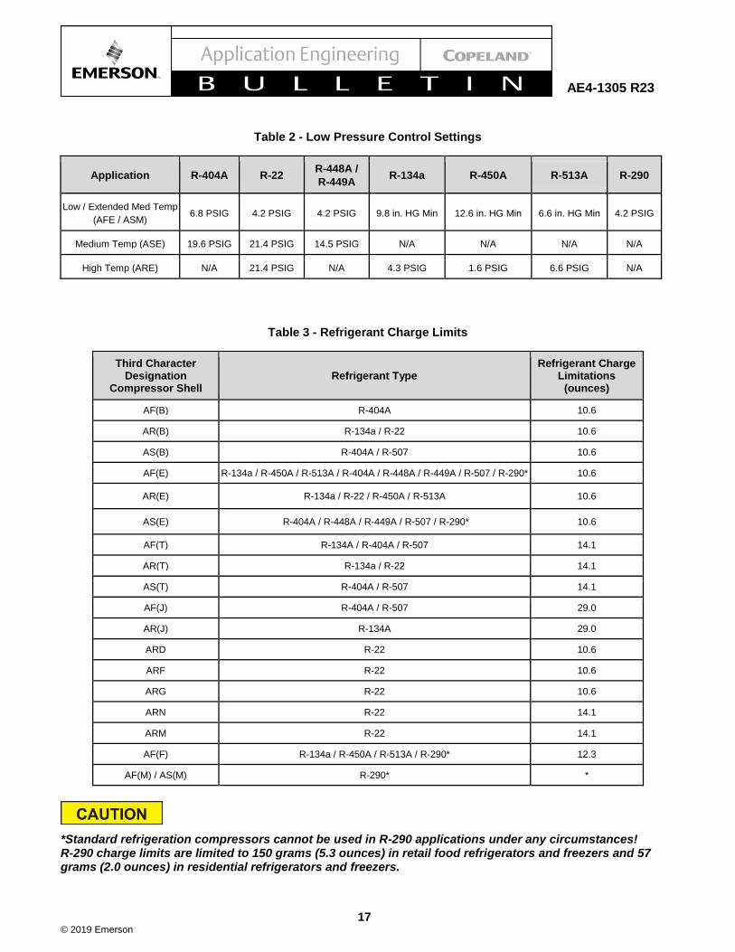
Table 2 - Low Pressure Control Settings
Application R-404A R-22 R-448A /
R-449A R-134a R-450A R-513A R-290
Low / Extended Med Temp
(AFE / ASM) 6.8 PSIG 4.2 PSIG 4.2 PSIG 9.8 in. HG Min 12.6 in. HG Min 6.6 in. HG Min 4.2 PSIG
Medium Temp (ASE) 19.6 PSIG 21.4 PSIG 14.5 PSIG N/A N/A N/A N/A
High Temp (ARE) N/A 21.4 PSIG N/A 4.3 PSIG 1.6 PSIG 6.6 PSIG N/A
Table 3 - Refrigerant Charge Limits
Third Character Designation
Compressor Shell
Refrigerant Type
Refrigerant Charge Limitations
(ounces)
AF(B) R-404A 10.6
AR(B) R-134a / R-22 10.6
AS(B) R-404A / R-507 10.6
AF(E) R-134a / R-450A / R-513A / R-404A / R-448A / R-449A / R-507 / R-290* 10.6
AR(E) R-134a / R-22 / R-450A / R-513A 10.6
AS(E) R-404A / R-448A / R-449A / R-507 / R-290* 10.6
AF(T) R-134A / R-404A / R-507 14.1
AR(T) R-134a / R-22 14.1
AS(T) R-404A / R-507 14.1
AF(J) R-404A / R-507 29.0
AR(J) R-134A 29.0
ARD R-22 10.6
ARF R-22 10.6
ARG R-22 10.6
ARN R-22 14.1
ARM R-22 14.1
AF(F) R-134a / R-450A / R-513A / R-290* 12.3
AF(M) / AS(M) R-290* *
*Standard refrigeration compressors cannot be used in R-290 applications under any circumstances! R-290 charge limits are limited to 150 grams (5.3 ounces) in retail food refrigerators and freezers and 57 grams (2.0 ounces) in residential refrigerators and freezers.

© 2019 Emerson
18
AE4-1305 R23
Table 4 - Mounting Kits
Third Character Designation Compressor shell series
Emerson Part Number
Frequency
AF(B) 527-C001-02
50 & 60 Hertz
AR(B) 527-C001-02
AS(B) 527-C001-02
AF(E) 527-C001-02
AR(E) 527-C001-02
AS(E) 527-C001-02
AF(T) 527-C001-00
AR(T) 527-C001-00
AS(T) 527-C001-00
ARD 527-C001-02
ARF 527-C001-02
ARG 527-C001-02
AF(F) 527-C001-00
AF(M) 527-C001-00
AS(M) 527-C001-00
Table 5 - DLT Controls
Discharge Line Temperature Cut Out (220°F cut out)
Tube Size (in.) Kit # Part #
1/4 998-7022-08 085-7022-13
3/8 998-7022-01 085-7022-07
The contents of this publication are presented for informational purposes only and are not to be construed as warranties or guarantees, express or implied,
regarding the products or services described herein or their use or applicability. Emerson Climate Technologies, Inc. and/or its affiliates (collectively
"Emerson"), as applicable, reserve the right to modify the design or specifications of such products at any time without notice. Emerson does not assume
responsibility for the selection, use or maintenance of any product. Responsibility for proper selection, use and maintenance of any Emerson product
remains solely with the purchaser or end user.