Embed Size (px)
Citation preview

®
USE
R’S
GU
IDE
envi
ron
men
tal m
on
itori
ng
un
it
Contents
Introduction--1
Product Description . . . . . . . . . . . . . . . . . . . . . . . . . . . . . . . . . . 1Features of the Environmental Monitoring Unit 1Initial setup 1
Internal Management Features. . . . . . . . . . . . . . . . . . . . . . . . . . . 3Overview 3Login control 3Types of user accounts 4
How to Recover from a Lost Password. . . . . . . . . . . . . . . . . . . . . . 5Upgrading Firmware. . . . . . . . . . . . . . . . . . . . . . . . . . . . . . . . . . 6Rear Panel . . . . . . . . . . . . . . . . . . . . . . . . . . . . . . . . . . . . . . . . . 8
Link-RX/TX (10/100) LED 9Status LED 9
Watchdog Features . . . . . . . . . . . . . . . . . . . . . . . . . . . . . . . . . 11Overview 11Network interface watchdog mechanism 11Resetting the network timer 11
Web Interface--12
How to Log On . . . . . . . . . . . . . . . . . . . . . . . . . . . . . . . . . . . . 12Overview 12Supported Web browsers 13URL address formats 14
Summary Page . . . . . . . . . . . . . . . . . . . . . . . . . . . . . . . . . . . . . 15Status 15Quick status tab 17Navigation menu 17
Navigation Menu . . . . . . . . . . . . . . . . . . . . . . . . . . . . . . . . . . . 18Overview 18Select a menu to perform a task 19Help menu 20Links menu 21
i

®
USE
R’S
GU
IDE
envi
ron
men
tal m
on
itori
ng
un
it
Control Console--22
How to Log On . . . . . . . . . . . . . . . . . . . . . . . . . . . . . . . . . . . . 22Overview 22Remote access to the control console 22Local access to the control console 23
Main Screen. . . . . . . . . . . . . . . . . . . . . . . . . . . . . . . . . . . . . . . 24Example main screen 24Information and status fields 24
Control Console Menus . . . . . . . . . . . . . . . . . . . . . . . . . . . . . . . 27Menu structure 27Main menu 28Device Manager option 28Network option 28System option 29
Environmental Monitoring Unit Menus--30
Environment Menu. . . . . . . . . . . . . . . . . . . . . . . . . . . . . . . . . . 30Environmental Probes 30Alarm Map Types 31Cooling Solutions(Rack ARUs) 31
Input Contacts . . . . . . . . . . . . . . . . . . . . . . . . . . . . . . . . . . . . . 33Output Relays . . . . . . . . . . . . . . . . . . . . . . . . . . . . . . . . . . . . . 34
Control Relays 34Configure Relays 34
Beacon . . . . . . . . . . . . . . . . . . . . . . . . . . . . . . . . . . . . . . . . . . 35Control the Beacon 35
Device Info . . . . . . . . . . . . . . . . . . . . . . . . . . . . . . . . . . . . . . . 36Detailed Status (control console only) 36Device Configuration 36
Event-Related Menus--37
Introduction . . . . . . . . . . . . . . . . . . . . . . . . . . . . . . . . . . . . . . 37Overview 37Menu options 38
Event Log . . . . . . . . . . . . . . . . . . . . . . . . . . . . . . . . . . . . . . . . 39Overview 39
ii

®
USE
R’S
GU
IDE
envi
ron
men
tal m
on
itori
ng
un
it
Logged events 40Web interface 40Control console 41How to use FTP or SCP to retrieve log files 41
Event Actions (Web Interface Only) . . . . . . . . . . . . . . . . . . . . . . 44Overview 44Severity levels 45Event log action 45Syslog action 46SNMP traps action 46Email action 46
Event Recipients. . . . . . . . . . . . . . . . . . . . . . . . . . . . . . . . . . . . 47Overview 47Trap receiver settings 47
E-mail Feature . . . . . . . . . . . . . . . . . . . . . . . . . . . . . . . . . . . . . 48Overview 48DNS servers 49SMTP settings 49Email recipients 50
How to Configure Individual Events . . . . . . . . . . . . . . . . . . . . . . 53Event List page 53Detailed Event Action Configuration page 53
Data Menu (Web Interface Only)--54
Log Option . . . . . . . . . . . . . . . . . . . . . . . . . . . . . . . . . . . . . . . 54Configuration Option . . . . . . . . . . . . . . . . . . . . . . . . . . . . . . . . 55
Network Menu--56
Introduction . . . . . . . . . . . . . . . . . . . . . . . . . . . . . . . . . . . . . . 56Overview 56Menu options 57
Option Settings . . . . . . . . . . . . . . . . . . . . . . . . . . . . . . . . . . . . 58TCP/IP 58DNS 62Ping utility (control console) 63FTP Server 63Telnet/SSH 64
iii

®
USE
R’S
GU
IDE
envi
ron
men
tal m
on
itori
ng
un
it
SNMP 70Email 71Syslog 72Web/SSL/TLS 76
System Menu--83
Introduction . . . . . . . . . . . . . . . . . . . . . . . . . . . . . . . . . . . . . . 83Overview 83Menu options 84
Option Settings . . . . . . . . . . . . . . . . . . . . . . . . . . . . . . . . . . . . 85User Manager 85Identification 86Date & Time 86Tools 88Preferences (Web interface) 89Links (Web interface) 89About System (Control console) 90
Boot Mode--92
Introduction . . . . . . . . . . . . . . . . . . . . . . . . . . . . . . . . . . . . . . 92Overview 92DHCP & BOOTP boot process 93
DHCP Configuration Settings . . . . . . . . . . . . . . . . . . . . . . . . . . . 95Environmental Monitoring Unit settings 95DHCP response options 97
Security--101
Security Features . . . . . . . . . . . . . . . . . . . . . . . . . . . . . . . . . . 101Planning and implementing security features 101Summary of access methods 101Changing default user names and passwords immediately 103Port assignments 103User names, passwords, community names (SNMP) 104
Authentication . . . . . . . . . . . . . . . . . . . . . . . . . . . . . . . . . . . . 105Authentication versus encryption 105MD5 authentication (for the Web interface) 106
Encryption. . . . . . . . . . . . . . . . . . . . . . . . . . . . . . . . . . . . . . . 108
iv

®
USE
R’S
GU
IDE
envi
ron
men
tal m
on
itori
ng
un
it
Secure SHell (SSH) and Secure CoPy (SCP) 108Secure Socket Layer (SSL)/Transport Layer Security (TLS) 110
Creating and Installing Digital Certificates . . . . . . . . . . . . . . . . . 112Purpose 112Choosing a method for your system 113
Firewalls . . . . . . . . . . . . . . . . . . . . . . . . . . . . . . . . . . . . . . . . 119
Product Information--120
Limited warranty 120Warranty limitations 120Obtaining service 121Recycling the Battery 121
Life-Support Policy . . . . . . . . . . . . . . . . . . . . . . . . . . . . . . . . . 122General policy 122Examples of life-support devices 122
Index--124
APC Worldwide Customer Support . . . . . . . . . . . . . . . . . . . . . . 131 . . . . . . . . . . . . . . . . . . . . . . . . . . . . . . . . . . . . . . . . . . . . . . 131
v

®®®®
USE
R’S
GU
IDE
envi
ron
men
tal m
on
itori
ng
un
it
Introduction
Product Description
Features of the Environmental Monitoring Unit
The APC® Environmental Monitoring Unit is a rack-mountable product that monitors the essential functions needed to ensure the availability of the racks in a room. In addition, it uses multiple, open standards such as Telnet, HTTP, HTTPS, SSL, TLS, SCP, and SNMP to provide full management of supported devices. It provides the following features:
• Sensor monitoring through the A-link connections• Input Contact monitoring for use with dry contact sensors• Data and Event log accessible by Telnet, FTP, serial connection, or a
Web browser• SNMP traps and e-mail notifications based on the severity level of the
Environmental Monitoring Unit or embedded management card events• A selection of security protocols for authentication and encryption• Rack Air Removal Unit (ARU) monitoring
Initial setup
You must define three TCP/IP settings for the Environmental Monitoring Unit before it can operate on the network.
• IP address of the Environmental Monitoring Unit• Subnet mask• IP address of the default gateway
1

®®®®
USE
R’S
GU
IDE
envi
ron
men
tal m
on
itori
ng
un
it
See alsoTo configure the TCP/IP settings, see the Environmental Monitoring Unit Installation and Quick Start Manual, provided in printed form, and in PDF on the APC Environmental Management Utility CD.‘
To use a DHCP server to configure the TCP/IP settings at an Environmental Monitoring Unit, see Boot Mode.
2

®®®®
USE
R’S
GU
IDE
envi
ron
men
tal m
on
itori
ng
un
it
Internal Management Features
Overview
The Environmental Monitoring Unit has two user interfaces (control console and Web interface) which provide menus with options that allow you to manage the Environmental Monitoring Unit. You can also manage the Environmental Monitoring Unit through its SNMP interface by using a SNMP browser with the PowerNet MIB.
For more information about the Environmental Monitoring Unit’s user interfaces, see Control Console and Web Interface; for more information about how to use the PowerNet MIB with an SNMP browser, see the PowerNet® SNMP Management Information Base (MIB) Reference Guide (.\doc\en\990-6052E-EN.pdf), which is provided on the APC Environmental Management Utility CD.
Login control
Only one user at a time can log on to the Environmental Monitoring Unit to use its internal user interface features. The priority for access is as follows:
• Local access to the control console from a computer with a direct serial connection to the Environmental Monitoring Unit always has the highest priority
• Telnet or Secure SHell (SSH) access to the control console from a remote computer has the next highest priority
• Web access has the lowest priority
For information about how SNMP access to the Environmental Monitoring Unit is controlled, see SNMP.
3

®®®®
USE
R’S
GU
IDE
envi
ron
men
tal m
on
itori
ng
un
it
Types of user accounts
The Environmental Monitoring Unit has three levels of access (Administrator, Device Manager, and Read Only User), all of which are protected by user name and password requirements.
• An Administrator can use all of the management menus available in the control console and the Web interface. The Administrator’s default User Name and Password are both apc.
• A Device Manager can access only the Log option in the Events menu and use the Environmental Monitoring Unit, and Data menus. The Device Manager’s default User Name is device, and the default Password is apc.
• A Read Only User has the following restricted access:– Access through the Web interface only. – Access to the same menus as a Device Manager, but without the
capability to change configurations, control devices, or delete data. Links to configuration options are visible but are disabled, and the event and data logs display no Delete button.
The Read Only User’s default User Name is readonly, and the default Password is apc.
To set User Name and Password values for the three account types, see User Manager.
N
You must use the Web interface to configure values for the Read Only User.
4

®®®®
USE
R’S
GU
IDE
envi
ron
men
tal m
on
itori
ng
un
it
How to Recover from a Lost Password
You can use a local computer that connects to the Environmental Monitoring Unit through the serial port on the front panel of the unit.
1. Select a serial port at the local computer, and disable any service which uses that port.
2. Use the supplied smart-signaling cable (940-0103) to connect the selected port to the serial port on the front panel of the Environmental Monitoring Unit.
3. Run a terminal program (such as HyperTerminal) and configure the selected port for 9600 bps, 8 data bits, no parity, 1 stop bit, and no flow control. Save the changes.
4. Press ENTER twice to display the User Name prompt.5. Press the Reset button on the Environmental Monitoring Unit, which
causes the it to restart, a process that takes approximately 15 seconds.6. Press ENTER as many times as necessary to redisplay the User Name
prompt, then use apc for the user name and password. (If you take longer than 30 seconds to log on after the User Name prompt is redisplayed, you must start the login procedure again at step 4.)
7. From the Control Console menu, select System, then User Manager.
8. Select Administrator, and change the User Name and Password settings, both of which are now defined as apc.
9. Press CTRL-C and log off.
Reconnect any cable that you disconnected in step 2 and restart any service that you disabled in step 1.
5

®®®®
USE
R’S
GU
IDE
envi
ron
men
tal m
on
itori
ng
un
it
Upgrading Firmware
0You can use a local computer that connects to the Environmental Monitoring Unit through the serial port on the front panel of the unit.
1. Select a serial port at the local computer, and disable any service which uses that port.
2. Use the supplied smart-signaling cable (940-0103) to connect the selected port to the serial port on the front panel of the Environmental Monitoring Unit.
3. Run a terminal program (such as HyperTerminal) and configure the selected port for 9600 bps, 8 data bits, no parity, 1 stop bit, and no flow control. Save the changes.
4. Press ENTER twice to display the User Name prompt.5. Enter your user name and password (the default is apc for both), and
press the ENTER key.6. From the Control Console menu, select System, then Tools, then
XMODEM.7. At the prompt Perform transfer with XMODEM-CRC? Type YES,
and press ENTER.8. The system will then prompt you to choose a transfer rate and to
change your terminal settings to match the transfer rate. Press ENTER to set the Environmental Monitoring Unit to accept the download.
To download a firmware upgrade for your Environmental Monitoring Unit using FTP, see the Management Card Addendum on the provided APC Environmental Management Utility CD.
6

®®®®
USE
R’S
GU
IDE
envi
ron
men
tal m
on
itori
ng
un
it
9. In the terminal program, send the file using the XMODEM protocol. Upon completion of the transfer, the console will prompt you to restore the baud rate to normal.
The Environmental Monitoring Unit will restart when the download is complete.
Caution
Do not interrupt the download.
7

®®®®
USE
R’S
GU
IDE
envi
ron
men
tal m
on
itori
ng
un
it
Rear Panel
Item Description
� 24 VDC Inlet Provides power to the Environmental Monitoring Unit.
� Reset Button Resets the Environmental Monitoring Unit. This will not affect the operation of any connected devices.
� 10/100 & Status LEDs See Link-RX/TX (10/100) LED and Status LED.
� User Contact Input Connections
Provides four user input connections for connecting normally open or normally closed sensor devices.
� Local Temperature and Humidity Probe Connections
Connect two local temperature/humidity sensors (AP9512TBLK).
� A-Link Ports Connect to remote temperature/humidity sensors and other devices through the A-Link connection.
� Alarm Beacon Port Connect to the beacon.
� Output Relay Connect to other equipment for mapping Environmental Monitoring Unit events to outside devices.
� � �� � � �
AlarmBeacon
Output
Probe 2Probe 1
RX / TXStatus
10 = Green100 = Orange
Temperature/HumidityUser Contact Inputs
1 2 3 4
–+–+ –+–+ResetPower
�
8

®®®®
USE
R’S
GU
IDE
envi
ron
men
tal m
on
itori
ng
un
it
Link-RX/TX (10/100) LED
The Link RX/TX LED indicates the network connection status of the Environmental Monitoring Unit.
Status LED
This LED indicates the network status of the Environmental Monitoring Unit.
Condition Description
Off One of the following situations exist:• The Environmental Monitoring Unit is not receiving input
power• The Environmental Monitoring Unit is starting up. • The Environmental Monitoring Unit is not operating properly.
It may need to be repaired or replaced. Contact APC Worldwide Customer Support.
Solid Green The device is connected to a network operating at 10 Megabits per second (Mbps).
Solid Orange The device is connected to a network operating at 100 Megabits per second (Mbps).
Flashing Green The device is recieving or transmitting data packets at 10 Megabits per second (Mbps).
Flashing Orange The device is recieving or transmitting data packets at 100 Megabits per second (Mbps).
Condition Description
Off The Environmental Monitoring Unit has no power.
Solid Green The Environmental Monitoring Unit has valid TCP/IP settings.
Flashing Green The Environmental Monitoring Unit does not have valid TCP/IP settings.1
9
®®®®
USE
R’S
GU
IDE
envi
ron
men
tal m
on
itori
ng
un
it
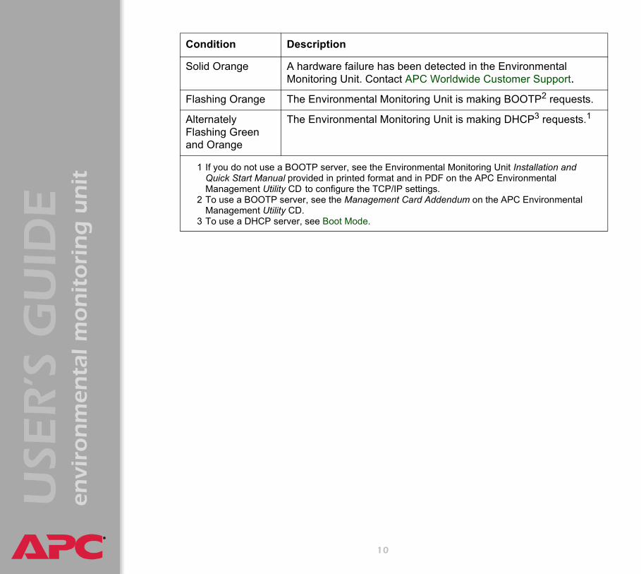
Solid Orange A hardware failure has been detected in the EnvironmentalMonitoring Unit. Contact APC Worldwide Customer Support.Flashing Orange The Environmental Monitoring Unit is making BOOTP2 requests.
Alternately Flashing Green and Orange
The Environmental Monitoring Unit is making DHCP3 requests.1
1 If you do not use a BOOTP server, see the Environmental Monitoring Unit Installation and Quick Start Manual provided in printed format and in PDF on the APC Environmental Management Utility CD to configure the TCP/IP settings.
2 To use a BOOTP server, see the Management Card Addendum on the APC Environmental Management Utility CD.
3 To use a DHCP server, see Boot Mode.
Condition Description
10

®®®®
USE
R’S
GU
IDE
envi
ron
men
tal m
on
itori
ng
un
it
Watchdog Features
Overview
To detect internal problems and recover from unanticipated inputs, the Environmental Monitoring Unit uses internal, system-wide watchdog mechanisms. When it reboots itself to recover from an internal problem, a System: Warmstart event is recorded in the event log.
Network interface watchdog mechanism
The Environmental Monitoring Unit implements internal watchdog mechanisms to protect itself from becoming inaccessible over the network. For example, if the Environmental Monitoring Unit does not receive any network traffic for 9.5 minutes (either direct traffic, such as SNMP, or broadcast traffic, such as an Address Resolution Protocol [ARP] request), it assumes that there is a problem with its network interface and restarts itself.
Resetting the network timer
To ensure that the Environmental Monitoring Unit does not restart if the network is quiet for 9.5 minutes, the Environmental Monitoring Unit attempts to contact the Default Gateway every 4.5 minutes. If the gateway is present, it responds to the Environmental Monitoring Unit, and that response restarts the 9.5-minute timer. If your application does not require or have a gateway, specify the IP address of a computer that is running on the network most of the time and is on the same subnet. The network traffic of that computer will restart the 9.5-minute timer frequently enough to prevent the Environmental Monitoring Unit from restarting.
11

®®®®
USE
R’S
GU
IDE
envi
ron
men
tal m
on
itori
ng
un
it
Web Interface
How to Log On
Overview
You can use a Environmental Monitoring Unit’s DNS name or System IP address for the URL address of the Web interface. Use your case-sensitive User Name and Password settings to log on. The default user name differs by account type:
• apc for an Administrator• device for a Device Manager• readonly for a Read Only User
The default password is apc for all three account types.
For information about the Web page that appears when you log on to the Web interface, see Summary Page.
If you are using HTTPS (SSL/TSL) as your access protocol, your login credentials are compared with information in a server certificate. If the certificate was created with the APC Security Wizard, you must use an IP address to log on to the Environmental Monitoring Unit if an IP address was specified as the common name in the certificate, or you must use a DNS name to log on if a DNS name was specified as the common name in the certificate.
12
®®®®
USE
R’S
GU
IDE
envi
ron
men
tal m
on
itori
ng
un
it
Supported Web browsers
As your browser, you can use Microsoft® Internet Explorer (IE) 5.0 (and higher) or Netscape® 4.0.8 (and higher, except Netscape 6.x) to access the Environmental Monitoring Unit through its Web interface. Other commonly available browsers also may work but have not been fully tested by APC.
Data verification, the event log, the data log, and Message Digest 5 (MD5) authentication require that you enable the following for your Web browser:
• JavaScript• Java• Cookies
In addition, the Environmental Monitoring Unit cannot work with a proxy server. Therefore, before you can use a Web browser to access its Web interface, you must do one of the following:
• Configure the Web browser to disable the use of a proxy server for the Environmental Monitoring Unit.
• Configure the proxy server so that it does not proxy the specific IP address of the Environmental Monitoring Unit.
13
®®®®
USE
R’S
GU
IDE
envi
ron
men
tal m
on
itori
ng
un
it
URL address formats
Type the DNS name or IP address of the Environmental Monitoring Unit in the Web browser’s URL address field and press ENTER. Except when you specify a non-default web server port in Internet Explorer, http:// or https:// is automatically added by the browser.
• For a DNS name of Web1, the entry would be one of the following:– http://Web1 if HTTP is your access mode– https://Web1 if HTTPS (SSL/TLS) is your access mode
• For a System IP address of 139.225.6.133, when the Environmental Monitoring Unit uses the default port (80) at the Web server, the entry would be one of the following:
– http://139.225.6.133 if HTTP is your access mode– https//139.225.6.133 if HTTPS (SSL/TLS) is your access
mode• For a System IP address of 139.225.6.133, when the Environmental
Monitoring Unit uses a non-default port (5000, in this example) at the Web server, the entry would be one of the following:
– http://139.225.6.133:5000 if HTTP is your access mode– https://139.225.6.133:5000 if HTTPS (SSL/TLS is your
access mode
If the error “You are not authorized to view this page” occurs (Internet Explorer only), another user is logged on to the Web interface or control console. If the error “No Response” (Netscape) or “This page cannot be displayed” (Internet Explorer) occurs, Web access may be disabled, or the Environmental Monitoring Unit may use a non-default Web-server port that you did not specify correctly in the address.
For more information, see Web/SSL/TLS.
14

®®®®
USE
R’S
GU
IDE
envi
ron
men
tal m
on
itori
ng
un
it
Summary Page
When you log on to the Web interface at the Environmental Monitoring Unit, the status view is displayed at the right side of the screen, the quick status tab is displayed at the upper right, and the navigation menu is displayed at the left.
Status
The Status view has these sections:• The Device Overview section reports any active alarm or warning
conditions and displays a status for each device connected to your Environmental Monitoring Unit.
• The Input Contacts section lists the available input contacts and their present state. If the text is in red, the contact is in its fault state.
• Environment – Environmental Probes shows the status of up to two local Temperature probes directly connected to the Environmental
Type the Management Card’s DNS name or IP address in the Web browser’s URL address field and press ENTER . Except when you specify a non-default web server port in Internet Explorer, http:// or https:// is automatically added by the browser.
15

®®®®
USE
R’S
GU
IDE
envi
ron
men
tal m
on
itori
ng
un
it
Monitoring Unit, and up to eight remote probes connected through the A-link ports.
• Environment – Cooling Solutions displays the status of up to two Rack Air Removal Units.
• 10/100 Management Card Status shows the following: – Name, Contact, and Location information for the Environmental
Monitoring Unit.– Date and Time the screen was last refreshed.– User (Administrator, Device Manage, or Read Only) type.– How long (Up Time) the Environmental Monitoring Unit has been
running since it was last started or reset.
16

®®®®
USE
R’S
GU
IDE
envi
ron
men
tal m
on
itori
ng
un
it
Quick status tab
The quick status tab is displayed in the upper right of every screen in the Web interface. The tab displays a warning of any alarms and provides a link to the online help.
Navigation menu
Provides access to the available Environmental Monitoring Unit options.
Access the online help for the displayed page.
Click the green “device operating normally” icon to return to the status screen where the status for attached devices is displayed.
Click the “attention required” icon to return to the status screen where active warnings and alarms are displayed.
See Navigation Menu
17

®®®®
USE
R’S
GU
IDE
envi
ron
men
tal m
on
itori
ng
un
it
Navigation Menu
Overview
When you log on to the Web interface, the navigation menu (left frame) includes the following elements:
• IP address of the Environmental Monitoring Unit • Environmental Monitoring Unit menus to manage the Environmental
Monitoring Unit and its components– Environment menu– Input Contacts menu– Output Relays menu– Beacon menu– Device Info menu
• Menus to manage the event log, data log, network connection, and system parameters
– Events menu– Data menu– Network menu– System menu
• Logout option• Help menu• Links menu
When you log on as a Device Manager or Read Only user, the Network and System menus do not appear in the navigation menu.
18

®®®®
USE
R’S
GU
IDE
envi
ron
men
tal m
on
itori
ng
un
it
Select a menu to perform a task
To do the following, see Environment Menu:• Configure the local and remote environmental probes.• Monitor Rack Air Removal Units connected to the Environmental
Monitoring Unit.
To do the following, see Input Contacts menu:• Rename or change the normal state of a contact.• Change the alarm map for each input contact.
To do the following, see Output Relays menu:• Rename or change the normal state of the relay.• Change the state of the output relay.
To activate the beacon, see Alarm Beacon.
To change the name of the Environmental Monitoring Unit, see the Device Info menu.
To do the following, see Event-Related Menus:• Access the event log.• Configure the actions to be taken based on an event’s severity level.• Configure SNMP Trap Receiver settings for sending event-based
traps.• Define who will receive e-mail notifications of events.• Test e-mail settings.
To do the following, see Network Menu:• Configure new TCP/IP settings for the Environmental Monitoring Unit.• Identify the Domain Name Service (DNS) Server and test the network
connection to that server.
19

®®®®
USE
R’S
GU
IDE
envi
ron
men
tal m
on
itori
ng
un
it
• Define settings for FTP, Telnet, SSH, the Web interface, SNMP, e-mail, and SSL/TLS.
• Configure the Environmental Monitoring Unit’s Syslog message feature.
To do the following, see System Menu:• Control Administrator, Device Manager, and Read Only user
access.• Define the system Name, Contact, and Location values.• Set the date and time used by the Environmental Monitoring Unit.• Restart the Environmental Monitoring Unit.• Reset control console settings to default settings.• Define the URL addresses of the user links and APC logo links in the
Web interface, as described in Links menu.
Help menu
When you click Help, the Contents for all of the online help is displayed. However, from any Web interface pages, you can use the question mark (?) in the quick status bar to link to the section of the online help for that page.
The Help menu also has an About System option you use to view information about the Environmental Monitoring Unit’s Model Number, Serial Number, Hardware Revision, Manufacture Date, MAC Address, Application Module and APC OS (AOS) Module, including the date and time each of the two modules were created.
In the control console, the About System option, which is a System menu option, identifies the Flash Type used.
20

®®®®
USE
R’S
GU
IDE
envi
ron
men
tal m
on
itori
ng
un
it
Links menu
Provides three user-definable URL link options. By default, these links access the following APC Web pages:
• APC’s Web Site accesses the APC home page.• Testdrive Demo accesses a demonstration page where you can use
samples of APC web-enabled products.• APC Monitoring accesses the “APC Remote Monitoring Service”
page about pay-for-monitoring services available from APC.
To redefine these links so that they point to other URLs:1. Click on Links in the System menu.2. Define any new names for User Links.3. Define any new URL addresses that you want User Links to access.
Only HTTP links may be defined.4. Click Apply.
The link associated with the APC logo is also definable.
21

®®®®
USE
R’S
GU
IDE
envi
ron
men
tal m
on
itori
ng
un
it
Control Console
How to Log On
Overview
You can use either a local (serial) connection, or a remote (Telnet) connection to access the control console.
Use case-sensitive User Name and Password entries to log on (by default, apc and apc, for an Administrator, or device and apc, for a Device Manager). A Read Only User has no access to the control console.
Remote access to the control console
You can use Telnet to log on to the control console. 1. At a command prompt, type telnet and the System IP address for
the Environmental Monitoring Unit (when the Environmental Monitoring Unit uses the default Telnet port of 23), and then press ENTER. For example: telnet 139.225.6.133
2. Enter your user name and password.
If you cannot remember your user name or password, see How to Recover from a Lost Password.
If the Environmental Monitoring Unit uses a non-default port number (between 5000 and 32767), you must include a colon or a space (depending on your Telnet client) after the IP address and then the port number.
22

®®®®
USE
R’S
GU
IDE
envi
ron
men
tal m
on
itori
ng
un
it
Local access to the control console
You can use a local computer that connects to the Environmental Monitoring Unit through the serial port on the front panel of the unit.
1. Select a serial port at the local computer, and disable any service which uses that port.
2. Use the supplied serial cable (940-0103) to connect the selected port to the serial port on the front panel of the Environmental Monitoring Unit.
3. Run a terminal program (such as HyperTerminal) and configure the selected port for 9600 bps, 8 data bits, no parity, 1 stop bit, and no flow control. Save the changes.
4. Press ENTER twice to display the User Name prompt.
23
®®®®
USE
R’S
GU
IDE
envi
ron
men
tal m
on
itori
ng
un
it
Main Screen
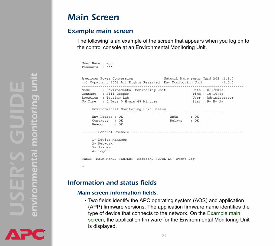
Example main screen
The following is an example of the screen that appears when you log on to the control console at an Environmental Monitoring Unit.
Information and status fields
Main screen information fields. • Two fields identify the APC operating system (AOS) and application
(APP) firmware versions. The application firmware name identifies the type of device that connects to the network. On the Example main screen, the application firmware for the Environmental Monitoring Unit is displayed.
User Name : apcPassword : ***
American Power Conversion Network Management Card AOS v1.1.7(c) Copyright 2003 All Rights Reserved Env Monitoring Unit v1.0.0-------------------------------------------------------------------------------Name : Environmental Monitoring Unit Date : 8/1/2003Contact : Bill Cooper Time : 10:16:58Location : Testing Lab User : AdministratorUp Time : 0 Days 0 Hours 43 Minutes Stat : P+ N+ A+
Environmental Monitoring Unit Status--------------------------------------------------------------------------Env Probes : OK ARUs : OKContacts : OK Relays : OKBeacon : OK
------- Control Console -------------------------------------------------------
1- Device Manager2- Network3- System4- Logout
<ESC>- Main Menu, <ENTER>- Refresh, <CTRL-L>- Event Log
>
24

®®®®
USE
R’S
GU
IDE
envi
ron
men
tal m
on
itori
ng
un
it
Network Management Card AOS v1.1.6Env Monitoring Unit APP v1.0.0
• Three fields identify the system Name, Contact, and Location values.Name : Environmental Monitoring UnitContact : Bill CooperLocation : Testing Lab
• An Up Time field reports how long the Environmental Monitoring Unit has been running since it was last reset or since power was applied.Up Time : 0 Days 0 Hours 43 Minutes
• Two fields identify the date and time the last time the screen refreshed.Date : 4/5/2003Time : 10:16:58
• A User field identifies whether you logged on as Administrator or Device Manager.User : Administrator
To set the Name, Contact, and Location values, see System Menu.
25

®®®®
USE
R’S
GU
IDE
envi
ron
men
tal m
on
itori
ng
un
it
Main screen status fields. • A Stat field reports the Environmental Monitoring Unit status.Stat : P+ N+ A+
Environmental Monitoring Unit status fields.
The status fields display the status of each of the devices that the Environmental Monitoring Unit can monitor. OK, Fault Present, or No Device Found is displayed.
P+ The APC operating system (AOS) is functioning properly.
N+ The network is functioning properly.
N? A BOOTP request cycle is in progress.
N– The Environmental Monitoring Unit failed to connect to the network.
N! Another device is using the IP address of the Environmental Monitoring Unit.
A+ The application is functioning properly.
A– The application has a bad checksum.
A? The application is initializing.
A! The application is not compatible with the AOS.
If the AOS status is not P+, contact APC Worldwide Customer Support, even if you can still access the Environmental Monitoring Unit.
26

®®®®
USE
R’S
GU
IDE
envi
ron
men
tal m
on
itori
ng
un
it
Control Console Menus
Menu structure
The menus in the control console list options by number and name. To use an option, type the option’s number and press ENTER, then follow any on-screen instructions.
For menus that allow you to change a setting you must use the Accept Changes option to save the changes you made.
While in a menu, you can also do the following:• Type ? and press ENTER to access brief menu option descriptions (if
the menu has help available).• Press ENTER to refresh the menu.• Press ESC to go back to the menu from which you accessed the
current menu.• Press CTRL-C to return to the main (control console) menu.• Press CTRL-L to access the event log.
For information about the event log, see Event-Related Menus.
27
®®®®
USE
R’S
GU
IDE
envi
ron
men
tal m
on
itori
ng
un
it
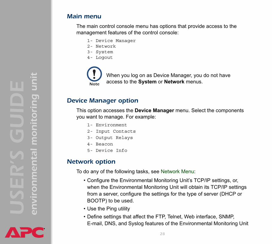
Main menu
The main control console menu has options that provide access to the management features of the control console:
1- Device Manager2- Network3- System4- Logout
s
Device Manager option
This option accesses the Device Manager menu. Select the components you want to manage. For example:
1- Environment
2- Input Contacts
3- Output Relays
4- Beacon
5- Device Info
Network option
To do any of the following tasks, see Network Menu:
• Configure the Environmental Monitoring Unit’s TCP/IP settings, or, when the Environmental Monitoring Unit will obtain its TCP/IP settings from a server, configure the settings for the type of server (DHCP or BOOTP) to be used.
• Use the Ping utility• Define settings that affect the FTP, Telnet, Web interface, SNMP,
E-mail, DNS, and Syslog features of the Environmental Monitoring Unit
When you log on as Device Manager, you do not have access to the System or Network menus.
28

®®®®
USE
R’S
GU
IDE
envi
ron
men
tal m
on
itori
ng
un
it
System option
To do any of the following tasks, see System Menu:• Control Administrator and Device Manager access• Define the system Name, Contact, and Location values• Set the date and time used by the Environmental Monitoring Unit• Restart the Environmental Monitoring Unit• Reset control console settings to their default values• Access system information about the Environmental Monitoring Unit
29
®®®®
USE
R’S
GU
IDE
envi
ron
men
tal m
on
itori
ng
un
it
Environmental Monitoring Unit Menus
Environment Menu
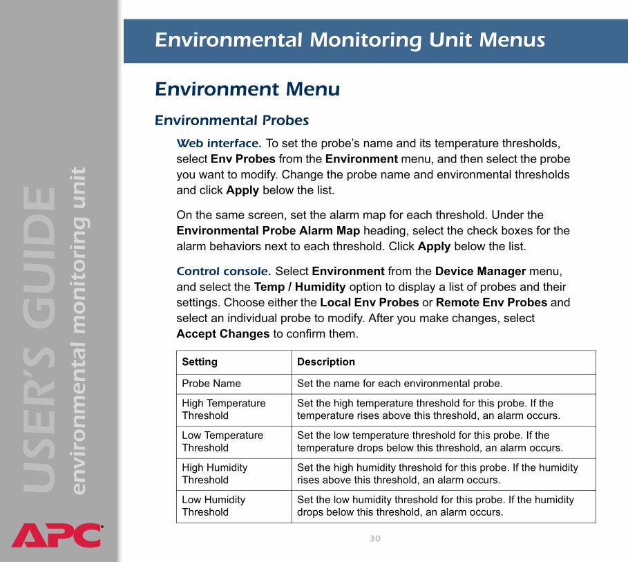
Environmental Probes
Web interface. To set the probe’s name and its temperature thresholds, select Env Probes from the Environment menu, and then select the probe you want to modify. Change the probe name and environmental thresholds and click Apply below the list.
On the same screen, set the alarm map for each threshold. Under the Environmental Probe Alarm Map heading, select the check boxes for the alarm behaviors next to each threshold. Click Apply below the list.
Control console. Select Environment from the Device Manager menu, and select the Temp / Humidity option to display a list of probes and their settings. Choose either the Local Env Probes or Remote Env Probes and select an individual probe to modify. After you make changes, select Accept Changes to confirm them.
Setting Description
Probe Name Set the name for each environmental probe.
High Temperature Threshold
Set the high temperature threshold for this probe. If the temperature rises above this threshold, an alarm occurs.
Low Temperature Threshold
Set the low temperature threshold for this probe. If the temperature drops below this threshold, an alarm occurs.
High Humidity Threshold
Set the high humidity threshold for this probe. If the humidity rises above this threshold, an alarm occurs.
Low Humidity Threshold
Set the low humidity threshold for this probe. If the humidity drops below this threshold, an alarm occurs.
30

®®®®
USE
R’S
GU
IDE
envi
ron
men
tal m
on
itori
ng
un
it
Alarm Map Types
Events can be mapped to a behavior. When the event occurs, the Environmental Monitoring Unit can take one or more of the following actions:
Cooling Solutions(Rack ARUs)
Web interface. Select Environment and then Cooling from the navigation menu. The Rack Air Removal Unit Status and Rack Air Removal Unit Alarms are displayed. To configure one of the ARUs, select its name to display the Rack Air Removal Unit Configuration and Rack Air Removal Unit Alarm Map Configuration screen. Make changes to the name and the alarm map settings from this screen. Click the Apply button for each section to confirm your changes.
High Temperature Alarm map
Map the high temperature alarm threshold to an alarm type, relay, or outlet.
Low Temperature Alarm map
Map the low temperature alarm threshold to an alarm type, relay, or outlet.
High Humidity Alarm map
Map the high humidity alarm threshold to an alarm type, relay, or outlet.
Low Humidity Alarm map
Map the low humidity alarm threshold to an alarm type, relay, or outlet.
Setting Description
Alarm Map Description
Beacon Activate the alarm beacon.
Relay Change the state of the Relay to its fault state.
31

®®®®
USE
R’S
GU
IDE
envi
ron
men
tal m
on
itori
ng
un
it
Control console. On the Device Manager menu select Environment, and then Rack ARUs. Configure any of the displayed ARUs or select Alarm Details for a list of the firmware revisions and active alarms for each ARU.
Setting Description
ARU Name Set a name for this Rack ARU.
Alarm Map Map the change of state for this Rack ARU to a relay, or the beacon. See Alarm Map Types for the specific behaviors to which events can be mapped.
32

®®®®
USE
R’S
GU
IDE
envi
ron
men
tal m
on
itori
ng
un
it
Input Contacts
Web interface. To view the status of the input contacts, select Input Contacts from the navigation menu. Click Configure to change input contact settings.Control console. To change the input contact settings, select Input Contacts from the Device Manager menu and select a contact to modify.
Setting Descriptions
Name Set the name for this input contact.
Normal State Set this contact to either normally open or normally closed.
Alarm Map Map the change of state for this contact to a relay, or the beacon. See Alarm Map Types for the specific behaviors to which events can be mapped.
33

®®®®
USE
R’S
GU
IDE
envi
ron
men
tal m
on
itori
ng
un
it
Output Relays
Control Relays
Web interface. To control the output relay, select Output Relays from the navigation menu. Click Control/Configure to change the output relay settings. To change the state of a relay manually, choose an action from the Action drop-down list and click Apply.
Control console. To control the output relays from the control console, select Output Relays from the Device Manager menu and then select Control Relay 1.
Configure Relays
Web interface. To configure the output relays, select Output Relays from the navigation menu, and then click Control/Configure. Under Output Relay Configuration, change the Name and Normal State for this output relay.
Control console. To configure the output relay from the control console, select Output Relays from the Device Manager menu and select Configure Relay 1 from the Output Relays menu.
Setting Description
Action (Web)
Open or Close (Console)
Manually open or close this relay.
Setting Description
Name Set the name for this output relay.
Normal State Set this relay to normally open or normally closed.
34

®®®®
USE
R’S
GU
IDE
envi
ron
men
tal m
on
itori
ng
un
it
Beacon
Control the Beacon
Web interface. To start or stop the beacon, select Beacon from the navigation menu and then click Control. Choose an action from the Action drop-down list and click Apply.
Control console. To control the beacon from the control console, select Beacon from the Device Manager menu. Select Immediate On or Immediate Off from the Beacon menu.
Setting Description
Action Start or stop the beacon.
35

®®®®
USE
R’S
GU
IDE
envi
ron
men
tal m
on
itori
ng
un
it
Device Info
Detailed Status (control console only)
Control console. The Detailed Status screen displays the status of the Input Contacts, Output Relay, and the Temperature probes.
Select Device Info from the Device Manager menu and then select Detailed Status.
Device Configuration
Web interface. To configure Device Parameters, select Device Info from the navigation menu, and click Configure in the Device Parameters field.
Control console. To configure the Environmental Monitoring Unit, select Device Info from the Device Manager menu, then select Environmental Monitoring Unit Configuration.
For similar information on the Web interface, see Summary Page.
Setting Description
Device Name Set the name for the Environmental Monitoring Unit.
36

®®®®
USE
R’S
GU
IDE
envi
ron
men
tal m
on
itori
ng
un
it
Event-Related Menus
Introduction
Overview
The Events menu provides access to the options that you use to do the following tasks:
• Access the event log• Define the actions to be taken when an event occurs, based on the
severity level of that event– Event logging– SNMP trap notification– E-mail notification
• Define up to four SNMP trap receivers, by Network Management Station (NMS)-specific IP address, for event notifications by SNMP traps.
• Define up to four recipients for event notifications by e-mail.
You can use only the Web interface to define which events will use which actions, as described in Event Log and How to Configure Individual Events.
37

®®®®
USE
R’S
GU
IDE
envi
ron
men
tal m
on
itori
ng
un
it
Menu options
In the Web interface, all of the events options are accessed through the Events menu.
In the control console, access the available events-related options as follows:
• Use the Email option in the Network menu to define the SMTP server and e-mail recipients.
• Use the SNMP option in the Network menu to define the SNMP trap receivers.
• Use Ctrl-L to access the event log from any menu.
For information on the following topics, use these links:
• Event Log• Event Actions (Web Interface Only)• Event Recipients• E-mail Feature• How to Configure Individual Events
38

®®®®
USE
R’S
GU
IDE
envi
ron
men
tal m
on
itori
ng
un
it
Event Log
Overview
The Environmental Monitoring Unit supports event-logging for all Environmental Monitoring Unit application firmware modules. To record and display Environmental Monitoring Unit and embedded managment card events, use any of the following to view the event log:
• Web interface • Control console• FTP• SCP
39

®®®®
USE
R’S
GU
IDE
envi
ron
men
tal m
on
itori
ng
un
it
Logged events
By default, the following events are logged:• Any event that causes an SNMP trap, except for SNMP authentication
failures.• The Environmental Monitoring Unit’s abnormal internal system events
To disable the logging of events based on their assigned severity level, use the Actions option in the Web interface’s Events menu.
Web interface
The Log option in the Events menu accesses the event log. This log displays all of the events that have been recorded since the log was last deleted, in reverse chronological order. The Delete Log button clears all events from the log.
See Event Actions (Web Interface Only).
Some System (embedded management card) events do not have a severity level. Even if you disable the event log for all severity levels, events with no severity level will still be logged.
To access a list of the System (embedded management card) and Environmental Monitoring Unit (Device) events, see Event List page.
40

®®®®
USE
R’S
GU
IDE
envi
ron
men
tal m
on
itori
ng
un
it
Control console
Press CTRL-L to display up to 300 events from the event log, in reverse chronological order. Use the SPACE BAR to scroll through the recorded events. While viewing the log, type d and press ENTER to clear all events from the log..
How to use FTP or SCP to retrieve log files
If you are an Administrator or Device Manager, you can use FTP or SCP to retrieve a tab-delineated event log file (event.txt) or data log file (data.txt) that you can import into a spreadsheet application.
• The file reports all of the events or data recorded since the log was last deleted.
• The file includes information that the event log or data log does not display.
– The version of the file format (first field)– The date and time the file was retrieved– The Name, Contact, and Location values and IP address of the
Environmental Monitoring Unit– The unique Event Code for each recorded event (event.txt file
only)
After events are deleted, they cannot be retrieved.
The Environmental Monitoring Unit uses a four-digit year for log entries. You may need to select a four-digit date format in your spreadsheet application to display all four digits of the year.
41

®®®®
USE
R’S
GU
IDE
envi
ron
men
tal m
on
itori
ng
un
it
If you are using the encryption-based security protocols for your system, use Secure CoPy (SCP) to retrieve the log file. (You should have FTP disabled.)
If you are using unencrypted authentication methods for the security of your system, use FTP to retrieve the log file.
To use SCP to retrieve the files. To use SCP to retrieve the event.txt file, use the following command:
scp username@hosthame_or_ip_address:event txt ./event.txt
To use SCP to retrieve the data.txt file, use the following command:
scp username@hosthame_or_ip_address:data.txt ./data.txt
To use FTP to retrieve the files. To use FTP to retrieve the event.txt or data.txt file:
1. At a command prompt, type ftp and the Environmental Monitoring Unit’s IP address, and press ENTER.
If the Port setting for FTP Server in the Network menu has changed from its default value (21), you must use the non-default value in the FTP command. For Windows FTP clients, use the following command, including spaces. (For some FTP clients, you must use a colon instead of a space between the IP address and the port number.)ftp>open ip_address port_number
See Security for information on the available protocols and methods for setting up the type of security appropriate for your needs.
To use non-default port values to enhance security, see Port assignments.
42

®®®®
USE
R’S
GU
IDE
envi
ron
men
tal m
on
itori
ng
un
it
2. Use the case-sensitive User Name and Password for either an Administrator or a Device Manager user to log on.– For Administrator, apc is the default for User Name and Password.– For Device Manager, device is the default for User Name, and apc
is the default for Password.3. Use the get command to transmit the text-version of the event log or
data log to your local drive.ftp>get event.txt
orftp>get data.txt
4. You can use the del command to clear the contents of the event log or data log.ftp>del event.txt
orftp>del data.txt
You will not be asked to confirm the deletion. – If you clear the data log, the event log records a deleted-log event.– If you clear the event log, a new event.txt file is created to record the
deleted-log event.5. Type quit at the ftp> prompt to exit from FTP.
43

®®®®
USE
R’S
GU
IDE
envi
ron
men
tal m
on
itori
ng
un
it
Event Actions (Web Interface Only)
Overview
Use the Actions option in the Events menu to do the following:• Select which actions will occur for events that have a severity level:
– Event Log selects which severity levels cause an event to be recorded in the event log.
.
– Syslog selects which severity levels cause messages to be sent to Syslog servers to log events.
– SNMP Traps selects which severity levels cause SNMP traps to be generated.
– Email selects which severity levels cause e-mail notifications..
• Click Details for a complete list of the Environmental Monitoring Unit (device), embedded managment card (system) events that can occur, and then edit the actions that will occur for an individual event.
• Click Hide Details to return to the Actions option.
See Event log action.
See Syslog action.
See SNMP traps action.
See Email action.
See How to Configure Individual Events.
44

®®®®
USE
R’S
GU
IDE
envi
ron
men
tal m
on
itori
ng
un
it
Severity levels
Except for some system (Environmental Monitoring Unit) events that do not have a severity level, events are assigned a default severity level.
• Informational: Indicates an event that requires no action, such as a notification of a return from an abnormal condition.
• Warning: Indicates an event that may need to be addressed if the condition continues, but which does not require immediate attention.
• Severe: Indicates an event that requires immediate attention. – Unless resolved, severe UPS and Environmental Monitoring Unit
events can cause incorrect operation of the UPS or its supported equipment, or can result in the loss of UPS protection during a power failure.
– Severe Environmental monitoring device events warn of abnormal environmental conditions or possible security violations.
Event log action
You can disable the recording of events in the event log. By default, all events are recorded, even events that have no severity level assigned.
Even if you disable the event log action for all severity levels, system (embedded management card) events that have no severity level assigned will still be logged.
For more information about this log, see Event Log.
45

®®®®
USE
R’S
GU
IDE
envi
ron
men
tal m
on
itori
ng
un
it
Syslog action
By default, the Syslog action is enabled for all events that have a severity level. However, before you can use this feature to send Syslog messages when events occur, you must configure it.
SNMP traps action
By default, the SNMP Traps action is enabled for all events that have a severity level assigned. However, before you can use SNMP traps for event notifications, you must identify the network management stations (NMSs) that will receive the traps by their IP addresses.
Email action
By default, the Email action is enabled for all events that have a severity level assigned. However, before you can use e-mail for event notifications, you must define the e-mail recipients. \
See Syslog.
To define up to four NMSs as trap receivers, see Event Recipients.
See E-mail Feature.
46

®®®®
USE
R’S
GU
IDE
envi
ron
men
tal m
on
itori
ng
un
it
Event Recipients
Overview
The Web interface and control console both have options that allow you to define up to four trap receivers and up to four e-mail addresses to be used when an event occurs that has the SNMP traps or e-mail enabled.
Trap receiver settings
To define which NMSs will receive traps:• In the Web interface, use the Recipients option of the Events menu.• In the control console, use the SNMP option in the Network menu.
Choose one of the trap receivers to modify, or select Settings and enable SNMP access for all trap receivers.
See Event Actions (Web Interface Only)
To identify the servers that will receive Syslog messages, see Syslog.
Item Definition
Community Name This setting defines the password (maximum of 15 characters) used when traps are sent to the NMS identified by the Receiver NMS IP setting.
Receiver NMS IP Identifies by IP address the NMS that will receive traps. If this setting is 0.0.0.0 (the default value), traps will not be sent to any NMS.
Generation (Web interface)
Trap Generation (control console)
Enables (by default) or disables the sending of any traps to the NMS identified by the Receiver NMS IP setting.
Authentication Traps Enables or disables the sending of authentication traps to the NMS identified by the Receiver NMS IP setting.
47

®®®®
USE
R’S
GU
IDE
envi
ron
men
tal m
on
itori
ng
un
it
E-mail Feature
Overview
You can use the Simple Mail Transfer Protocol (SMTP) to send e-mail to up to four recipients when an event occurs.
To use the e-mail feature, you must define the following settings:
• The IP addresses of the primary and secondary Domain Name Service (DNS) servers.
• The DNS name of the SMTP server and the From Address setting for SMTP.
• The e-mail addresses for a maximum of four recipients.
See DNS servers.
See SMTP settings.
See Email recipients.
48

®®®®
USE
R’S
GU
IDE
envi
ron
men
tal m
on
itori
ng
un
it
DNS servers
The Environmental Monitoring Unit cannot send any e-mail messages unless the IP address of the primary DNS server is defined.
The Environmental Monitoring Unit will wait a maximum of 15 seconds for a response from the primary or (if specified) the secondary DNS server. If the Environmental Monitoring Unit does not receive a response within that time, e-mail cannot be sent. Therefore, use DNS servers that are on the same segment as the Environmental Monitoring Unit or on a nearby segment (but not across a WAN).
Once you define the IP addresses of the DNS servers, verify that DNS is working correctly. Enter the DNS name of a computer on your network to test whether you can look up the IP address for that DNS name.
SMTP settings
The Email option in the Network menu accesses the following settings:
7
See DNS
Setting Description
SMTP Server Defines the SMTP server by its DNS name.
NOTE: This definition is required only when the SMTP Server option (see Email recipients) is set to Local.
From Address Defines the contents of the From field in the e-mail messages sent by the Environmental Monitoring Unit.
NOTE: The SMTP server’s configuration may require that you use a valid user account on the server for this setting. See the server’s documentation for more information.
49

®®®®
USE
R’S
GU
IDE
envi
ron
men
tal m
on
itori
ng
un
it
Email recipients
In the Web interface, the Recipients option of the Events menu or the Configure the Email recipients link in the Email Configuration page accesses the settings you use to identify up to four e-mail recipients.
In the Web interface, use the Email Test option to send a test message to a configured recipient.
In the control console, the Email option of the Network menu accesses the e-mail recipients settings.
Setting Description
To Address Defines the user and domain names of the recipient. • To bypass the DNS lookup of the mail server’s IP address, use the IP address
in brackets instead of the e-mail domain name. For example, use jsmith@[xxx.xxx.xxx.xxx] instead of [email protected]. This is useful when DNS lookups are not working correctly.
• To use e-mail for paging, use the e-mail address for that recipient’s pager gateway account (for example, [email protected]). The pager gateway pages the recipient. The recipient’s pager must be able to use text-based messaging.
50

®®®®
USE
R’S
GU
IDE
envi
ron
men
tal m
on
itori
ng
un
it
SMTP ServerSelects one of the following methods for routing e-mail:• Through the SMTP server provided with the Environmental Monitoring Unit
(the recommended option, Local). This option ensures that the e-mail is sent before the 20-second time-out for the Environmental Monitoring Unit, and, if necessary, is retried several times. Also do one of the following:
• Enable forwarding at the SMTP server provided with the Environmental Monitoring Unit so that it can route e-mail to external SMTP servers. Typically, SMTP servers are not configured to forward e-mail. Always check with the administrator of your SMTP server before changing its configuration to allow forwarding.
• Set up a special e-mail account for the Environmental Monitoring Unit to forward e-mail to an external mail account.
• Directly to the recipient’s SMTP server (the Recipient’s option). On a busy remote SMTP server, the time-out may prevent some e-mail from being sent, and with this option the Environmental Monitoring Unit tries to send the e-mail only once.
When the recipient uses the SMTP server provided with the Environmental Monitoring Unit, the Recipient’s setting has no effect.
Generation Enables (by default) or disables sending e-mail to the recipient.
Setting Description
51

®®®®
USE
R’S
GU
IDE
envi
ron
men
tal m
on
itori
ng
un
it
Format Selects the format used for e-mail messages:Short: Identifies only the event that occurred. For example:Environmental Monitoring Unit: Output Relay abnormal condition
Long: Includes information about the Environmental Monitoring Unit, and the event. For example:
Name: TestLabLocation: Building 3Contact: DonAdamshttp://139.225.6.133Environmental Monitoring Unit Ser #: WS0131005294Date: 3/10/2003Time: 16:09:48Code: 0x120C Warning - Environmental Monitoring Unit: Output Relay abnormal condition
Setting Description
52

®®®®
USE
R’S
GU
IDE
envi
ron
men
tal m
on
itori
ng
un
it
How to Configure Individual Events
Event List page
The Actions option in the Events menu opens the Event Action Configuration page on the Web interface. Use the Details button in this page to access a complete list of the events that can be reported by your Environmental Monitoring Unit.
Each event is identified by its unique code, its description, and its assigned severity level. For example:
Detailed Event Action Configuration page
The event codes provide a link to a page that allows you to do the following:• Change the selected event’s severity level• Enable or disable whether the event uses the Event Log, Syslog
messages, SNMP traps, or e-mail notifications
Modifying events on the Configure Event Action by Severity Level page will override any changes you have made to individual events on the Details page.
Code Description Severity
0x0002 System: Warmstart Severe
0x0F15 Environmental Monitoring Unit: Output Relay abnormal condition
Warning
For information about severity levels and how they define the actions associated with events, see Event Actions (Web Interface Only).
53

®®®®
USE
R’S
GU
IDE
envi
ron
men
tal m
on
itori
ng
un
it
Data Menu (Web Interface Only)
Log Option
Use this option to access a log that stores readings taken by the temperature probes at regular intervals.The information in the data log is sampled and stored based on the log interval defined by the Data menu’s Configuration option. Each entry is listed by the date and time the data was recorded, and provides the data in a column format.
See Configuration Option.
For descriptions of the recorded data that is specific to your Environmental Monitoring Unit, see the online help in your Environmental Monitoring Unit’s Web interface
For information about how you can retrieve the Data Log as a text file, see How to use FTP or SCP to retrieve log files.
54

®®®®
USE
R’S
GU
IDE
envi
ron
men
tal m
on
itori
ng
un
it
Configuration Option
Use this option to access the Data Log Configuration page. This page reports how much data can be stored in the data log based on the Log Interval setting, which defines how often data will be sampled and recorded in the data log. If you change the Log Interval, the report updates to reflect the effect of the new setting.The minimum interval is one minute; the maximum interval is 18 hours, 12 minutes, and 15 seconds.
55

®®®®
USE
R’S
GU
IDE
envi
ron
men
tal m
on
itori
ng
un
it
Network Menu
Introduction
Overview
The Network menu has the options that you use to do the following tasks:• Define TCP/IP settings, including DHCP or BOOTP server settings,
when one of those types of servers is used to provide the required TCP/IP values
• Use the Ping utility• Define and display settings that affect the Environmental Monitoring
Unit’s settings for DNS, FTP, Telnet, SSH, SNMP, E-mail, Syslog, and the Web interface (SSL/TLS)
Only an Administrator has access to the Network menu.
56

®®®®
USE
R’S
GU
IDE
envi
ron
men
tal m
on
itori
ng
un
it
Menu options
Unless noted, the following menu options are available in the control console and Web interface:
• TCP/IP• DNS• Send DNS Query (Web interface only)• Ping utility (control console)• FTP Server• Telnet/SSH• SNMP• Email• Syslog• Web/SSL/TLS
57

®®®®
USE
R’S
GU
IDE
envi
ron
men
tal m
on
itori
ng
un
it
Option Settings
TCP/IP
This option accesses the following settings:• A Boot mode setting selects the method used to define the three
TCP/IP values that a Environmental Monitoring Unit needs to operate on the network:
– System IP: The IP address of the Environmental Monitoring Unit– Subnet Mask: The subnet mask value– Default Gateway: The IP address of the default gateway
• Advanced settings define the Environmental Monitoring Unit’s host and domain names, as well as TCP/IP port, BOOTP, and DHCP settings used by the Environmental Monitoring Unit.
Current TCP/IP settings fields. The current System IP, Subnet Mask, and Default Gateway values, along with the Environmental Monitoring Unit’s MAC Address, Host Name, Domain Name, and Ethernet Port Speed values are displayed above the TCP/IP settings in the control console and the Web interface.
See also
For information about how to configure the initial TCP/IP settings when you install the Environmental Monitoring Unit, see the Environmental Monitoring Unit Installation and Quick Start Manual (.\emu\doc\en\990-1442-EN.pdf), provided on the APC APC Environmental Management Utility CD and in printed form.
58

®®®®
USE
R’S
GU
IDE
envi
ron
men
tal m
on
itori
ng
un
it
Boot mode setting. This setting selects which method will be used to define the Environmental Monitoring Unit’s TCP/IP settings whenever the Environmental Monitoring Unit starts, resets, or reboots:
• Manual: Three settings (System IP, Subnet Mask, and Default Gateway) that are only available when Manual is used to define the needed TCP/IP settings.
• BOOTP only: A BOOTP server provides the TCP/IP settings.• DHCP only: A DHCP server provides the TCP/IP settings.• DHCP & BOOTP: The Environmental Monitoring Unit will attempt to
get its TCP/IP settings from a BOOTP server first, and then, if it cannot discover a BOOTP server, from a DHCP server.
An After IP Assignment setting will, by default, switch Boot mode from its default DHCP & BOOTP setting to BOOTP only or DHCP only, depending on the type of server that supplied the TCP/IP settings to the Environmental Monitoring Unit. For information about the After IP Assignment setting, and other settings that affect how the Environmental Monitoring Unit uses BOOTP and DHCP, see Advanced settings; For more information about how to use DHCP, see Boot Mode.
See also
For more information about how to use BOOTP, see the Addendum (.\Doc\eng\addendum.pdf) provided on the APC Environmental Management Utility CD.
59

®®®®
USE
R’S
GU
IDE
envi
ron
men
tal m
on
itori
ng
un
it
Advanced settings. The Boot mode affects which settings are available:• Two settings is available for all Boot mode selections to define the
Environmental Monitoring Unit’s Host Name and Domain Name values.
• A Port Speed setting is available for all Boot mode selections to define the TCP/IP port’s communication speed (Auto-negotiate, by default).
• Three settings are available for all Boot mode selections, except Manual, to identify the Environmental Monitoring Unit in BOOTP or DHCP communication:
– Vendor Class: Uses APC, by default.– Client ID: Uses the Environmental Monitoring Unit’s MAC
address, by default..
– User Class: Uses the Environmental Monitoring Unit’s application module type, by default. For example, the Environmental Monitoring Unit module sets the User Class to GW.
Caution
If the Client ID is changed from the Environmental Monitoring Unit’s MAC address, the new value must be unique on the LAN. Otherwise, the DHCP or BOOTP server may act incorrectly.
60

®®®®
USE
R’S
GU
IDE
envi
ron
men
tal m
on
itori
ng
un
it
• Two settings are available when BOOTP only is the Boot mode selection:
– Retry Then Fail: Defines how many times the Environmental Monitoring Unit will attempt to discover a BOOTP server before it stops (4, by default).
– On Retry Failure: Defines what TCP/IP settings will be used by the Environmental Monitoring Unit when it fails to discover a BOOTP server (Use Prior Settings, by default).
For information about the Advanced settings (DHCP Cookie Is and Retry Then Stop) that directly affect how DHCP is used, see Boot Mode
61

®®®®
USE
R’S
GU
IDE
envi
ron
men
tal m
on
itori
ng
un
it
DNS
Use these fields to define the IP addresses of the primary and secondary Domain Name Servers (DNS) used by the Environmental Monitoring Unit e-mail feature.
Send DNS Query (Web interface only). Use this option, available only through the TCP/IP & DNS menu in the Web interface, to send a DNS query that tests the setup of your DNS servers.
Use the following settings to define the parameters for the test DNS request. View the result of the test DNS request in the Last Query Response field (Passed, Failed, or Not Responding).
• Use the Query Type setting to select the method to use for the DNS query:
– URL name of the server (By Name)– IP address of the server (By IP)– Mail Exchange used by the server (By MX)
• Use the Query Question text field to specify the value to be used for the selected Query Type:
– For Name, specify the URL.– For IP, specify the IP address.– For MX, specify the Mail Exchange address.
• Use DNS Server to Query to select whether to query the Primary DNS Server or the Secondary DNS Server.
See E-mail Feature and DNS servers.
62

®®®®
USE
R’S
GU
IDE
envi
ron
men
tal m
on
itori
ng
un
it
Ping utility (control console)
Select this option, available only in the control console, to check the network connection by testing whether a defined IP address responds to the Ping network utility.
By default, the IP address of the default gateway is used. However, you can use the IP address of any device known to be running on the network.
FTP Server
Use the Access setting to enable or disable the FTP server. The server is enabled by default.
Use the Port setting to identify the TCP/IP port that the FTP server uses for communications with the Environmental Monitoring Unit. The default Port setting is 21.
You can change the Port setting to any unused port from 5000 to 32767 to enhance the protection provided by User Name and Password settings. You must then use a colon (:) in the command line to specify the non-default port. For example, for a port number of 5000 and a Environmental Monitoring Unit IP address of 159.215.12.114, you would use this command:
ftp 159.215.12.114:5000
FTP transfers files without using encryption. For higher security, use Secure CoPy (SCP) for file transfers. When you select and configure Secure SHell (SSH), SCP is enabled automatically. To configure SSH, see Telnet/SSH. If you decide to use SCP for file transfer, be sure to disable the FTP server.
To access a text version of the Environmental Monitoring Unit’s event or data Log, see How to use FTP or SCP to retrieve log files.
63

®®®®
USE
R’S
GU
IDE
envi
ron
men
tal m
on
itori
ng
un
it
Telnet/SSHUse the Telnet/SSH option to perform the following tasks:• Enable or disable Telnet or the Secure SHell (SSH) protocol for remote
control console access. – While SSH is enabled, you cannot use Telnet to access the control
console.– Enabling SSH enables SCP automatically.
– Do not enable both versions of SSH unless you require that both be activated at the same time. (Security protocols use extensive processing power.)
• Configure the port settings for Telnet and SSH.• Select one or more data encryption algorithms for SSH, version 1, SSH
version 2, or both.• In the Web interface, specify a host key file previously created with the
APC Security Wizard and load it to the Environmental Monitoring Unit.
See also
To use FTP to download configuration files, see the Management Card Addendum (./emu/doc/en/990-6015E-EN.pdf) on the APC Environmental Management Utility CD.
When SSH is enabled and its port and encryption ciphers configured, no further configuration is required to use SCP. (SCP uses the same configuration as SSH.)
To use SSH, you must have an SSH client installed. Most Linux and other UNIX® platforms include an SSH client as part of their installation, but Microsoft Windows operating systems do not. SSH clients are available from various vendors.
64

®®®®
USE
R’S
GU
IDE
envi
ron
men
tal m
on
itori
ng
un
it
• Display the fingerprint of the SSH host key for SSH versions 1 and 2. Most SSH clients display the fingerprint at the start of a session. Compare the fingerprint displayed by the client to the fingerprint that you recorded from the Web interface or control console of the Environmental Monitoring Unit.
From a command line interface, such as the command prompt on Windows operating systems, you can use FTP or Secure CoPy (SCP) to transfer the host key file. You must transfer the file to location /sec on the Environmental Monitoring Unit.
If you do not specify a host key file, the Environmental Monitoring Unit generates an RSA host key of 768 bits, instead of the 1024-bit RSA host key that the Wizard creates. The Environmental Monitoring Unit can take up to 5 minutes to create this host key, and SSH is not accessible during that time.
If you are using SSH version 2, expect a noticeable delay when logging on to the control console of the Environmental Monitoring Unit. Although the delay is not long, it can be mistaken for a problem because there is no explanatory message.
65

®®®®
USE
R’S
GU
IDE
envi
ron
men
tal m
on
itori
ng
un
it
66
Option Description
Telnet/SSH Network Configuration
Access Enables or disables the access method selected in Protocol Mode.
NOTE: Enabling SSH automatically disables Telnet. To enable SSH, change the setting and then click Next>> in the Web interface or choose Accept Changes in the control console. You must then agree to the license agreement that is displayed
Protocol Mode
Choose one of the following: • Telnet: User names, passwords, and data are transmitted without
encryption. • Secure SHell (SSH), version 1: User names, passwords and data are
transmitted in encrypted form. There is little or no delay when you are logging on.
• Secure SHell (SSH), version 2: User names, passwords and data are transmitted in encrypted form, but with somewhat more protection than version 1 from attempts to intercept, forge, or alter data during data transmission. There is a noticeable delay when you are logging on to the Environmental Monitoring Unit.
• Secure SHell (SSH), versions 1 and 2: Do not enable both versions of SSH unless you require that both be activated at the same time. (Security protocols use extensive processing power.)

®®®®
USE
R’S
GU
IDE
envi
ron
men
tal m
on
itori
ng
un
it
Telnet/SSH Port ConfigurationTelnet Port Identifies the TCP/IP port used for communications by Telnet with the Environmental Monitoring Unit. The default is 23.
You can change the Port setting to the number of any unused port between 5000 and 32768 to enhance the protection provided by User Name and Password settings. Then, according to the requirements of your Telnet client program, you must use either a colon (:) or a space in the command line to specify the non-default port number. For example, for a port number of 5000 and a Environmental Monitoring Unit IP address of 159.215.12.114, your Telnet client would require one or the other of the following commands:telnet 159.215.12.114:5000
telnet 159.215.12.114 5000
SSH Port Identifies the TCP/IP port used for communications by the Secure SHell (SSH) protocol with the Environmental Monitoring Unit. The default is 22.
You can change the Port setting to the number of any unused port between 5000 and 32768 to enhance the protection provided by User Name and Password settings. See the documentation for your SSH client for information on the command line format required to specify a non-default port number when starting SSH.
Option Description
67

®®®®
USE
R’S
GU
IDE
envi
ron
men
tal m
on
itori
ng
un
it
SSH Server ConfigurationSSHv1 Encryption Algorithms
Enables or disables DES, and displays the status (always enabled) of Blowfish, two encryption algorithms (block ciphers) compatible with SSH, version 1, clients.• DES: The key length is 56 bits.• Blowfish: The key length is 128 bits. You cannot disable this algorithm.
NOTE: Not all SSH clients can use every algorithm. If your SSH client cannot use Blowfish, you must also enable DES.
SSHv2 Encryption Algorithms
Enables or disables the following encryption algorithms (Block Ciphers) that are compatible with SSH version 2 clients.• 3DES (enabled by default): The key length is 168 bits.• Blowfish (enabled by default): The key length is 128 bits.• AES 128: The key length is 128 bits.• AES 256: The key length is 256 bits.
NOTE: Not all SSH clients can use every algorithm. Your SSH client selects the algorithm that provides the highest security from among the enabled algorithms that it is able to use. (If your SSH client cannot use either of the default algorithms, you must enable an AES algorithm that it can use.)
Option Description
68

®®®®
USE
R’S
GU
IDE
envi
ron
men
tal m
on
itori
ng
un
it
SSH User Host Key FileStatus: The Status field Indicates the status of the host key (private key). In the control console, you display host key status by selecting Advanced SSH Configuration.• SSH Disabled: No host key in use: No host key has been transferred
to the Environmental Monitoring Unit or a host key has been transferred improperly.
NOTE:A host key must be installed to the /sec directory of the Environmental Monitoring Unit
• Generating: The Environmental Monitoring Unit is generating a host key because no valid host key was installed in its /sec directory.
• Loading: A host key is being loaded (i.e., being activated on the Environmental Monitoring Unit).
• Valid: The host key is valid. (If you install an invalid host key, the Environmental Monitoring Unit discards it and generates a valid one. However, a host key that the Environmental Monitoring Unit generates is only 768 bits in length. A valid host key created by the APC Security Wizard is 1024 bits.)
Filename: You can create a host key file with the APC Security Wizard and then upload it to the Environmental Monitoring Unit by using the Web interface. Use the Browse button for the Filename field to locate the file, then click Apply.
Alternatively, you can use FTP or Secure CoPy (SCP) to transfer the host key file to the Environmental Monitoring Unit.
NOTE: Creating and uploading a host key in advance reduces the time required to enable SSH. If no host key is loaded when you enable SSH, the Environmental Monitoring Unit creates one when it reboots. The Environmental Monitoring Unit takes up to 5 minutes to create this key, and the SSH server is not accessible during that time.
Option Description
69

®®®®
USE
R’S
GU
IDE
envi
ron
men
tal m
on
itori
ng
un
it
SNMP
An Access option (the Settings option in the control console) enables (by default) or disables SNMP. When SNMP is enabled, the Access Control settings allow you to control how each of the four available SNMP channels is used.
SSH Host Key Fingerprint
SSH v1: Displays the SSH version 1 fingerprint for the host key. The fingerprint is a unique identifier to further authenticate the host key. In the control console, choose Advanced SSH Configuration and then Host Key Information to display the fingerprint.
SSH v2: Displays the SSH version 2 fingerprint for the host key. The fingerprint is a unique identifier to further authenticate the host key. In the control console, choose Advanced SSH Configuration and then Host Key Information to display the fingerprint.
Option Description
To define up to four NMSs to serve as trap receivers, see Trap receiver settings.
Setting Definition
Community Name
Defines the password (maximum of 15 characters) that an NMS defined by the NMS IP setting uses to access the channel.
NMS IP Limits access to the NMS or NMSs specified by the format used for the IP address.• 159.215.12.1 allows only the NMS with that IP address to have access.• 159.215.12.255 allows access for any NMS on the 159.215.12 segment.• 159.215.255.255 allows access for any NMS on the 159.215 segment.• 159.255.255.255 allows access for any NMS on the 159 segment.• 0.0.0.0 or 255.255.255.255 allows access for any NMS.
70

®®®®
USE
R’S
GU
IDE
envi
ron
men
tal m
on
itori
ng
un
it
Use this option to define two SMTP settings (SMTP Server and From Address) used by the e-mail feature of the Environmental Monitoring Unit.
Access Type
Selects how the NMS defined by the NMS IP setting can use the channel when that NMS uses the correct value for Community Name.
Read The NMS can use GETs at any time, but it can never use SETs.
Write The NMS can use GETs at any time, and can use SETs when no one is logged on to either the control console or Web interface.
Disabled The NMS cannot use GETs or SETs.
Write+ The NMS can use GETs and SETs at any time, even when someone is logged on to the control console or Web interface.
Setting Definition
See SMTP settings and E-mail Feature.
71

®®®®
USE
R’S
GU
IDE
envi
ron
men
tal m
on
itori
ng
un
it
Syslog
By default, the Environmental Monitoring Unit can send messages to up to four Syslog servers whenever Environmental Monitoring Unit or embedded management card events occur. The Syslog servers, which must be specifically identified by their IP address, record the events in a log that provides a centralized record of events that occur at network devices.
See also
This user’s guide does not describe Syslog, or the Syslog configuration values, in detail. For more information about Syslog, see RFC3164, a copy of which is available at www.ietf.org/rfc/rfc3164.
72

®®®®
USE
R’S
GU
IDE
envi
ron
men
tal m
on
itori
ng
un
it
Syslog settings. Leave the Syslog settings, except the Server IP settings, set to their defaults unless otherwise specified by the Syslog network or system administrator.
General Settings
Setting Definition
Access (Web interface)
Syslog (control console)
Enables (by default) or disables the Syslog feature.
Facility Selects the facility code assigned to the Environmental Monitoring Unit’s Syslog messages (User, by default).
NOTE: Although other selections are available, User is the selection that best defines the Syslog messages sent by a Environmental Monitoring Unit.
Syslog Server Settings
Server IP Uses specific IP addresses to identify which of up to four servers will receive Syslog messages sent by the Environmental Monitoring Unit.
NOTE: To use the Syslog feature, the Server IP address must be defined for at least one server.
Port Identifies the user datagram protocol (UDP) port that the Environmental Monitoring Unit will use to send Syslog messages. The default is 514, the number of the UDP port assigned to Syslog.
73

®®®®
USE
R’S
GU
IDE
envi
ron
men
tal m
on
itori
ng
un
it
Local Priority (Severity Mapping)
Map to Syslog’s Priorities
Maps each of the severity levels (Local Priority settings) that can be assigned to embedded management card and Environmental Monitoring Unit events to the available Syslog priorities. The following definitions are from RFC3164:• Emergency: The system is unusable• Alert: Action must be taken immediately• Critical: Critical conditions• Error: Error conditions• Warning: Warning conditions• Notice: Normal but significant conditions• Informational: Informational messages• Debug: Debug-level messages
The following are the default settings for the four Local Priority settings:• Severe is mapped to Critical• Warning is mapped to Warning• Informational is mapped to Info• None (for events which have no severity level assigned) is mapped
to InfoNOTE: To disable sending Syslog messages for Severe, Warning, or Informational events, see Event Actions (Web Interface Only).
74

®®®®
USE
R’S
GU
IDE
envi
ron
men
tal m
on
itori
ng
un
it
Syslog test (Web interface). This option allows you to send a test message to the Syslog servers configured in the Syslog Server section.
1. Select the Priority to assign to the test message.2. Define the Test Message using any text in the format described in
Syslog message format. For example, EMS: CommunicationsEstablished 0x0F01 meets the required message format.
3. Click Apply to have the Environmental Monitoring Unit send a Syslog message that uses the defined Priority and Test Message settings.
Syslog message format. A Syslog message has three parts:• The priority (PRI) part identifies the Syslog priority assigned to the
message’s event and the facility code assigned to messages sent by the Environmental Monitoring Unit.
• The Header includes a time stamp and the IP address of the Environmental Monitoring Unit.
• The message (MSG) part has two fields:– A TAG field, which is followed by a colon and a space, identifies
the event type (System or EMS, for example)– A CONTENT field provides the event text, followed by a space
and the event code
75
®®®®
USE
R’S
GU
IDE
envi
ron
men
tal m
on
itori
ng
un
it
Web/SSL/TLS
Use the Web/SSL/TLS menu to perform the following tasks.• Enable or disable the two protocols that provide access to the Web
interface of the Environmental Monitoring Unit:– Hypertext Transfer Protocol (HTTP) provides access by user
name and password, but does not encrypt user names, passwords, and data during transmission.
– Hypertext Transfer Protocol over Secure Socket Layer (HTTPS). Secure Socket Layer (SSL) encrypts user names, passwords, and data during transmission and provides authentication of the Environmental Monitoring Unit by means of digital certificates.
• Configure the ports that each of the two protocols will use.• Select the encryption ciphers that SSL will use.• Identify whether a server certificate is installed on the Environmental
Monitoring Unit. If a certificate has been created with the APC Security Wizard but is not installed:
– In the Web interface, browse to the certificate file and upload it to the Environmental Monitoring Unit.
– Alternatively, use the Secure CoPy (SCP) protocol or FTP to upload it to the location \sec on the Environmental Monitoring Unit
See Creating and Installing Digital Certificates to choose among the several methods for using digital certificates.
76

®®®®
USE
R’S
GU
IDE
envi
ron
men
tal m
on
itori
ng
un
it
• Display the configured parameters of a digital server certificate, if one is installed.
Creating and uploading a server certificate in advance reduces the time required to enable HTTPS (SSL/TLS). If no server certificate is loaded when you enable HTTPS (SSL/TLS), the Environmental Monitoring Unit creates one when it reboots. The Environmental Monitoring Unit can take up to 5 minutes to create this certificate, and the SSL/TLS server is not available during that time.
Option Description
Web/SSL/TLS Network Configuration
Access Enables or disables the access method selected in Protocol Mode.
Protocol Mode
Choose one of the following: • HTTP: User names, passwords, and data are transmitted without
encryption.• HTTPS (SSL/TLS): User names, passwords and data are transmitted in
encrypted form, and digital certificates are used for authentication.
NOTE: To enable HTTPS (SSL/TLS), change the setting and then click Next>> in the Web interface, or choose Accept Changes in the control console. You must then agree to the license agreement that is displayed. To activate the changes you must log off and log back on to the interface. When SSL is activated, your browser displays a lock icon, usually at the bottom of the screen.
77

®®®®
USE
R’S
GU
IDE
envi
ron
men
tal m
on
itori
ng
un
it
HTTP/HTTPS Port ConfigurationHTTP Port Identifies the TCP/IP port used for communications by HTTP with the Environmental Monitoring Unit. The default is 80.
You can change the Port setting to the number of any unused port between 5000 and 32768 to enhance the protection provided by User Name and Password settings.
You must then use a colon (:) in the command line to specify the non-default port number. For example, for a port number of 5000 and a Environmental Monitoring Unit IP address of 159.215.12.114, you would use this command:http://159.215.12.114:5000
HTTPS Port Identifies the TCP/IP port used for communications by HTTPS with the Environmental Monitoring Unit. The default is 443.
You can change the Port setting to the number of any unused port between 5000 and 32768 to enhance the protection provided by User Name and Password settings.
You must then use a colon (:) in the command line to specify the non-default port number. For example, for a port number of 6502 and a Environmental Monitoring Unit IP address of 159.215.12.114, you would use this command:https://159.215.12.114:6502
Option Description
78

®®®®
USE
R’S
GU
IDE
envi
ron
men
tal m
on
itori
ng
un
it
SSL/TSL Server ConfigurationCipherSuite Enables or disables the following SSL encryption ciphers and hash algorithms. (To access these options in the control console, choose Web/SSL/TLS, then Advanced SSL/TLS Configuration.)
NOTE: All of these encryption ciphers and hash algorithms use the RSA public key algorithm.• DES (SSL_RSA_WITH_DES_CBC_SHA): a block cipher with a key
length of 56 bits. The Secure Hash Algorithm (SHA) is used for authentication.
• 3DES (SSL_RSA_WITH_3DES_EDE_CBC_SHA): a block cipher with a key length of 168 bits. A Secure Hash Algorithm (SHA) is used for authentication.
• RC4 (SSL_RSA_WITH_RC4_128_MD5): a stream cipher with a key length of 128 bits, with an RSA key exchange algorithm, and with a Message Digest 5 (MD5) hash algorithm used for authentication. This selection is enabled by default.
• RC4 (SSL_RSA_WITH_RC4_128_SHA): a stream cipher with a key length of 128 bits. A Secure Hash Algorithm (SHA) is used for authentication. This selection is enabled by default.
Option Description
79

®®®®
USE
R’S
GU
IDE
envi
ron
men
tal m
on
itori
ng
un
it
SSL/TLS Server CertificateStatus: The Status field indicates whether a server certificate is installed. (To display the status in the control console, choose Web/SSL/TLS, then Advanced SSL/TLS Configuration.)• Not installed: No certificate is installed on the Environmental Monitoring
Unit.
NOTE:If you install a certificate by using FTP or SCP, you must specify the correct location (/sec) on the Environmental Monitoring Unit.
• Generating: The Environmental Monitoring Unit is generating a certificate because no valid certificate was installed.
• Loading: A certificate is being loaded (activated on the Environmental Monitoring Unit).
• Valid: A valid certificate was installed to or generated by the Environmental Monitoring Unit. (If you install an invalid certificate, the Environmental Monitoring Unit discards it and generates a valid one. However, a certificate that the Environmental Monitoring Unit generates has some limitations. See Method 1: Use APC’s default certificate.)
Filename: You can create a server certificate with the APC Security Wizard and then upload it to the Environmental Monitoring Unit by using the Web interface. Use the Browse button for the Filename field to locate the file, then click Apply. By default, the certificate is installed to the correct location.
Alternatively, you can use FTP or Secure CoPy (SCP) to transfer the server certificate to the Environmental Monitoring Unit. However, you must specify the correct location (/sec) on the Environmental Monitoring Unit.
NOTE: Creating and uploading a server certificate in advance reduces the time required to enable HTTPS (SSL/TLS). If no server certificate is loaded when you enable HTTPS (SSL/TLS), the Environmental Monitoring Unit creates one when it reboots. The Environmental Monitoring Unit can take up to 5 minutes to create this certificate, and the SSL/TLS server is not available during that time.
Option Description
80

®®®®
USE
R’S
GU
IDE
envi
ron
men
tal m
on
itori
ng
un
it
Parameter Description
Current Certificate Details
Issued to: Common Name (CN): The IP Address or DNS name of the Environmental Monitoring Unit, except if the server certificate was generated by default by the Environmental Monitoring Unit. For a default server certificate, the Common Name (CN) field displays the Environmental Monitoring Unit’s serial number.
NOTE: If an IP address was specified as the Common Name when the certificate was created, use an IP address to log on to the Web interface of the Environmental Monitoring Unit; if the DNS name was specified as the Common Name, use the DNS name to log on. When you log on, if you do not use the IP address or DNS name that was specified for the certificate, authentication fails, and you receive an error message asking if you want to continue.
Organization (O), Organizational Unit (OU), and Locality, Country: The name, organizational unit, and location of the organization that is using the server certificate. If the server certificate was generated by default by the Environmental Monitoring Unit, the Organizational Unit (OU) field displays “Internally Generated Certificate.”
Serial Number: The serial number of the server certificate.
Issued By: Common Name (CN): The Common Name as specified in the CA root certificate, except if the server certificate was generated by default by the Environmental Monitoring Unit. For a default server certificate, the Common Name (CN) field displays the Environmental Monitoring Unit’s serial number.
Organization (O) and Organizational Unit (OU): The name and organizational unit of the organization that issued the server certificate. If the server certificate was generated by default by the Environmental Monitoring Unit, the Organizational Unit (OU) field displays “Internally Generated Certificate.”
Validity Issued on: The date and time at which the certificate was issued.
Expires on: The date and time at which the certificate expires.
81

®®®®
USE
R’S
GU
IDE
envi
ron
men
tal m
on
itori
ng
un
it
Fingerprints Each of the two fingerprints is a long string of alphanumeric characterspunctuated by colons. A fingerprint is a unique identifier that you can use to further authenticate the server. Record the fingerprints to compare with the fingerprints contained in the certificate, as displayed in the browser.
SHA1 Fingerprint: This fingerprint is created by a Secure Hash Algorithm (SHA).
MD5 Fingerprint: This fingerprint is created by a Message Digest 5 (MD5) algorithm.
Parameter Description
82

®®®®
USE
R’S
GU
IDE
envi
ron
men
tal m
on
itori
ng
un
it
System Menu
Introduction
Overview
Use the System menu to do the following tasks:• Configure system identification, date and time settings, and
Administrator and Device manager access• Synchronize the real-time clock for the Environmental Monitoring Unit
with a Network Time Protocol (NTP) server• Reset or restart the Environmental Monitoring Unit• Define the URL links available in the Web interface• Set the units (Fahrenheit or Celsius) used for temperature displays• Access hardware and firmware information about the Environmental
Monitoring Unit • Download configuration files (control console only)
Only an Administrator has access to the System menu.
83

®®®®
USE
R’S
GU
IDE
envi
ron
men
tal m
on
itori
ng
un
it
Menu options
Unless noted, the following menu options are available in the control console and Web interface:
• User Manager• Identification• Date & Time• Tools• Preferences (Web interface)• Links (Web interface)• About System (Control console)
The About System option is a Help menu option in the Web interface.
84

®®®®
USE
R’S
GU
IDE
envi
ron
men
tal m
on
itori
ng
un
it
Option Settings
User Manager
Use this option to define the access values shared by the control console and the Web interface, and the authentication used to access the Web interface.
Setting Definition
Values affecting all users
Auto Logout The number of minutes (3 by default) before a user is automatically logged off because of inactivity.
Authentication The Basic setting (default) causes the Web interface to use standard HTTP 1.1 login (base64-encoded passwords); MD5 causes the Web interface to use an MD5-based authentication login.
NOTE: Cookies must be enabled at a browser before it can be used with MD5 authentication.
Separate values for Administrator, Device Manager, and Read Only User
User Name The case-sensitive name (maximum of 10 characters) used by Administrator and Device Manager users to log on at the control console or Web interface, and by the Read Only User to log on at the Web interface only.• apc, by default, for Administrator• device, by default, for Device Manager• readonly, by default, for the Read Only User.
Password The case-sensitive password (maximum of 10 characters) always used to log on at the control console, but only used to log on to the Web interface when Basic is selected for the Authentication setting (apc is the default for the Password settings for the three account types).
NOTE: A Read Only User is not permitted to log on through the control console.
85

®®®®
USE
R’S
GU
IDE
envi
ron
men
tal m
on
itori
ng
un
it
Identification
Use this option to define the System Name, Contact, and Location values used by the SNMP agent for the Environmental Monitoring Unit. The option’s settings provide the values used for the MIB-II sysName, sysContact, and sysLocation Object Identifications (OIDs)..
Date & Time
Use this option to set the date and time used by the Environmental Monitoring Unit. The option displays the current settings and allows you to change those settings manually or through a Network Time Protocol (NTP) Server.
Set Manually. Use this option in the Web interface, or Manual in the control console, to set Date and Time for the Environmental Monitoring Unit..
See also
For more information about the MIB-II OIDs, see the PowerNet® SNMP Management Information Base (MIB) Reference Guide (.emu\doc\en\6052C-EN.pdf) provided on the APC Environmental Management Utility CD.
An Apply Local Computer Time to Environmental Management System option, which is available in the Web interface only, sets these values to match the date and time settings of the computer you are using to access the Web interface.
86

®®®®
USE
R’S
GU
IDE
envi
ron
men
tal m
on
itori
ng
un
it
Synchronize with Network Time Protocol (NTP) Server. Use this option on the Web interface, or Network Time Protocol (NTP) on the control console, to have an NTP Server automatically update the Date and Time settings for the Environmental Monitoring Unit.
In the control console, use the NTP Client option to enable or disable the NTP Server updates. In the Web interface, use the Set Manually option. The updates are disabled by default.
Setting Definition
Primary NTP Server Identifies the IP address of the primary NTP server.
Secondary NTP Server Identifies the IP address of the secondary NTP server when a secondary server is available.
Time Zone Defines the offset to be used from Greenwich Mean Time (GMT) based on the time zone in which the Environmental Monitoring Unit is located.
Update Interval Defines how often, in weeks, the Environmental Monitoring Unit will access the NTP Server for an update (1 week minimum, 52 weeks maximum). Use Update Using NTP Now to initiate an immediate update as well.
87

®®®®
USE
R’S
GU
IDE
envi
ron
men
tal m
on
itori
ng
un
it
Tools
Use this option to restart the Environmental Monitoring Unit or to reset some or all of its configuration settings to their original default values.
Action Definition
No Action (Web Interface only)
No change to the Environmental Monitoring Unit.
Reboot Restarts the Environmental Monitoring Unit.
Reset to Defaults Resets all configuration settings. This option will reset the TCP/IP settings and enable DHCP and BOOTP.
Reset to Defaults Except TCP/IP
Resets all configuration settings except the TCP/IP settings.
Reset Only TCP/IP to Defaults
Resets the TCP/IP settings only.
NOTE: WIth Boot mode set to DHCP & BOOTP, its default setting, the Environmental Monitoring Unit’s TCP/IP settings must be defined by a DHCP or BOOTP server. See TCP/IP.
Delete SSH Host Keys and SSL Certificates
Removes any SSH host key and server certificate on the Environmental Monitoring Unit so that you can reconfigure these components of your security system.
XMODEM (serial connection only)
Allows you to download firmware using a terminal-emulation program when you use a local connection to the control console. To connect to the control console locally, see Local access to the control console.
88

®®®®
USE
R’S
GU
IDE
envi
ron
men
tal m
on
itori
ng
un
it
Preferences (Web interface)
Use this option to define whether temperature values are displayed as Fahrenheit or Celsius in the Web interface and the control console.
Links (Web interface)
Use this option to modify the links to APC Web pages..
Setting Definition
User Links
Name Defines the link names that appear in the Links menu (by default, APC’s Web Site, Testdrive Demo, and Remote Monitoring).
URL Defines the URL addresses used by the links. By default, the following URL addresses are used:• http://www.apc.com (APC’s Web Site)• http://testdrive.apc.com (Testdrive Demo)• http://rms.apc.com (Remote Monitoring)
Note: Only links of type http:// can be used in these fields.
For information about these pages see Links menu.
Access Links
APC Home Page Defines the URL address used by the APC logo at the top of all Web interface pages (by default, http://www.apc.com).
89

®®®®
USE
R’S
GU
IDE
envi
ron
men
tal m
on
itori
ng
un
it
About System (Control console)
This option identifies the following hardware information for the Environmental Monitoring Unit: Model Number, Serial Number, Hardware Revision, Manufacture Date, and MAC Address.
This screen also displays Name, Version, Date, and Time for the Application Module and AOS.
The About System menu also includes fields for system Flash Type and the Type, Sector, and CRC 16 for each module.
In the Web interface, except for Flash Type, this hardware information is reported by the About System option in the Help menu.
90

®®®®
USE
R’S
GU
IDE
envi
ron
men
tal m
on
itori
ng
un
it
91

®®®®
USE
R’S
GU
IDE
envi
ron
men
tal m
on
itori
ng
un
it
Boot Mode
Introduction
Overview
In addition to using a BOOTP server or manual settings, the Environmental Monitoring Unit can use a dynamic host configuration protocol (DHCP) server to provide the settings that it needs to operate on a TCP/IP network.
The method that is used to provide the network settings for the Environmental Monitoring Unit depends on Boot mode, a TCP/IP option in the Network menu. To use a DHCP server to provide the network assignment for the Environmental Monitoring Unit, Boot mode must be set to either DHCP & BOOTP, its default setting, or DHCP only.
See also
For more details on DHCP and DHCP options, see RFC2131 and RFC2132.
92

®®®®
USE
R’S
GU
IDE
envi
ron
men
tal m
on
itori
ng
un
it
DHCP & BOOTP boot process
When Boot mode is set to its default DHCP & BOOTP setting, the following occurs when the Environmental Monitoring Unit is started or reset:
1. The Environmental Monitoring Unit makes up to five requests for its network assignment from any BOOTP server. If a valid BOOTP response is received, the Environmental Monitoring Unit starts the network services and sets Boot mode to BOOTP Only.
2. If the Environmental Monitoring Unit fails to receive a valid BOOTP response after five BOOTP requests, the Environmental Monitoring Unit makes up to five requests for its network assignment from any DHCP server. If a valid DHCP response is received, the Environmental Monitoring Unit starts the network services and sets Boot mode to DHCP Only.
To configure the Environmental Monitoring Unit so that it always uses the DHCP & BOOTP setting for Boot mode, enable the Remain in DHCP & BOOTP mode after accepting TCP/IP settings option, which is disabled by default.
See Environmental Monitoring Unit settings.
93
®®®®
USE
R’S
GU
IDE
envi
ron
men
tal m
on
itori
ng
un
it
3. If the Environmental Monitoring Unit fails to receive a valid DHCP response after five DHCP requests, it repeats BOOTP and DHCP requests until it receives a valid network assignment. First it sends a BOOTP request every 32 seconds for 12 minutes, then it sends one DHCP request with a time-out of 64 seconds, and so forth.
If a DHCP server responds with an invalid offer (e.g., without the APC Cookie), the Environmental Monitoring Unit accepts the lease from that server on the last request of the sequence and immediately releases that lease. This prevents the DHCP server from reserving the IP Address associated with its invalid offer.
For more information on what a valid response requires, see DHCP response options.
94

®®®®
USE
R’S
GU
IDE
envi
ron
men
tal m
on
itori
ng
un
it
DHCP Configuration Settings
Environmental Monitoring Unit settings
The TCP/IP option in the Network menu of the Web interface and control console accesses the network settings for the Environmental Monitoring Unit.
Three settings (Port Speed, Host Name, and Domain Name) are available regardless of the TCP/IP option’s Boot mode selection, and three settings (Vendor Class, Client ID, and User Class) are available for any Boot mode selection except Manual.
When Boot mode is set to DHCP & BOOTP, two options are available:• After IP Assignment in the control console (or Remain in DHCP &
BOOTP mode after accepting TCP/IP settings in the Web interface): By default, this option switches Boot mode to DHCP Only or BOOTP Only, depending on the configuration of the server that provided the TCP/IP settings.
• DHCP Cookie Is in the control console (or Require vendor specific cookie to accept DHCP Address in the Web interface): By default, this option requires that the DHCP responses include the APC cookie in order to be valid.
For more information about the APC cookie, see DHCP response options.
95

®®®®
USE
R’S
GU
IDE
envi
ron
men
tal m
on
itori
ng
un
it
When Boot mode is set to DHCP Only, two options are available:• DHCP Cookie Is in the control console (or Require vendor specific
cookie to accept DHCP Address in the Web interface): By default, this option requires that the DHCP responses include the APC cookie in order to be valid.
• Retry Then Stop in the control console (or Maximum # of Retries in the Web interface): This option sets the number of times the Environmental Monitoring Unit will repeat the DHCP request if it does not receive a valid response. By default, the number of retries is 0, which sets the Environmental Monitoring Unit to continue repeating the DHCP request indefinitely.
For more information about the APC cookie, see DHCP response options
96

®®®®
USE
R’S
GU
IDE
envi
ron
men
tal m
on
itori
ng
un
it
DHCP response options
Each valid DHCP response contains options that provide the TCP/IP settings that the Environmental Monitoring Unit needs to operate on a network, and other information that affects the operation of the Environmental Monitoring Unit.
The Environmental Monitoring Unit uses the Vendor Specific Information option (option 43) in a DHCP response to determine whether the DHCP response is valid.
Vendor Specific Information (option 43). The Vendor Specific Information option contains up to two APC specific options encapsulated in a TAG/LEN/DATA format: the APC Cookie and the Boot Mode Transition.
APC Cookie. Tag 1, Len 4, Data “1APC”
Option 43 notifies the Environmental Monitoring Unit that a DHCP server has been configured to service APC devices. By default, the APC Cookie must be present in this DHCP response option before the Environmental Monitoring Unit can accept the lease.
Following, in hexadecimal format, is an example of a Vendor Specific Information option that contains the APC cookie:
Option 43 = 0x01 0x04 0x31 0x41 0x50 0x43
Use the DHCP Cookie Is setting described in Environmental Monitoring Unit settings to disable the APC cookie requirement.
97

®®®®
USE
R’S
GU
IDE
envi
ron
men
tal m
on
itori
ng
un
it
Boot Mode Transition. Tag 2, Len 1, Data 1/2
This option 43 setting enables or disables the After IP Assignment option which, by default, causes the Boot mode option to use the setting that reflects the server that provided the TCP/IP settings (DHCP Only or BOOTP Only):
• For a data value of 1, the After IP Assignment option is disabled, and the Boot mode option remains in its DHCP & BOOTP setting after successful network assignment. Whenever the Environmental Monitoring Unit restarts, it will request its network assignment first from a BOOTP server, and then, if necessary, from a DHCP server.
• For a data value of 2, the After IP Assignment option is enabled and the Boot mode option switches to DHCP Only when the Environmental Monitoring Unit accepts the DHCP response. Whenever the Environmental Monitoring Unit restarts, it will request its network assignment (TCP/IP settings) from a DHCP server only.
Following, in hexadecimal format, is an example of a Vendor Specific Information option that contains the APC cookie and the disable Boot Mode Transition setting:
Option 43 = 0x01 0x04 0x31 0x41 0x50 0x43 0x02 0x01 0x01
See DHCP & BOOTP boot process.
For more information about the After IP Assignment, see Environmental Monitoring Unit settings.
98

®®®®
USE
R’S
GU
IDE
envi
ron
men
tal m
on
itori
ng
un
it
TCP/IP options. The Environmental Monitoring Unit uses the following options within a valid DHCP response to define its TCP/IP settings:
• IP Address (from the yiaddr field of the DHCP response): Provides the IP address that the DHCP server is leasing to the Environmental Monitoring Unit.
• Subnet Mask (option 1): Provides the subnet mask value needed by the Environmental Monitoring Unit to operate on the network.
• Default Gateway (option 3): Provides the default gateway address needed by the Environmental Monitoring Unit to operate on the network.
• Address Lease Time (option 51): Identifies the length of time for the lease associated with the identified IP Address.
• Renewal Time, T1 (option 58): Identifies how long the Environmental Monitoring Unit must wait after an IP address lease is assigned before it can request a renewal of that lease.
• Rebinding Time, T2 (option 59): Identifies how long the Environmental Monitoring Unit must wait after an IP address lease is assigned before it can seek to rebind that lease.
99

®®®®
USE
R’S
GU
IDE
envi
ron
men
tal m
on
itori
ng
un
it
Miscellaneous options. The Environmental Monitoring Unit uses the following options within a valid DHCP response to define NTP, DNS, hostname, and domain name settings:
• NTP Server, Primary and Secondary (option 42): Identifies up to two NTP servers that can be used by the Environmental Monitoring Unit.
• NTP Time Offset (option 2): Specifies the offset, in seconds, of the subnet for the Environmental Monitoring Unit from Coordinated Universal Time (UTC).
• DNS Server, Primary and Secondary (option 6): Identifies one or two DNS servers that can be used by the Environmental Monitoring Unit.
• Host Name (option 12): Identifies the hostname (maximum length of 32 characters) to be used by the Environmental Monitoring Unit.
• Domain Name (option 15): Identifies the domain name (maximum length of 64 characters) to be used by the Environmental Monitoring Unit.
100

®®®®
USE
R’S
GU
IDE
envi
ron
men
tal m
on
itori
ng
un
it
Security
Security Features
Planning and implementing security features
As a network device that passes information across the network, the Environmental Monitoring Unit is subject to the same exposure as other devices on the network.
Use the information in this section to plan and implement the security features appropriate for your environment.
Summary of access methods
Serial control console.
Remote control console.
Security Access Description
Access is by user name and password.
Always enabled.
Security Access Description
Available methods:• User name and
password• Selectable server port• Server Enable/Disable• Secure SHell (SSH)
For high security, use SSH.• With Telnet, the user name and password are transmitted
as plain text.• SSH disables Telnet and provides encrypted access to the
control console interface to provide additional protection from attempts to intercept, forge, or alter data during data transmission.
101

®®®®
USE
R’S
GU
IDE
envi
ron
men
tal m
on
itori
ng
un
it
SNMP.
File transfer protocols.
Security Access Description
Available methods:• Community Name• NMS IP filters• Agent Enable/Disable• 4 access communities
with read/write/disable capability
The NMS IP filters allow access from designated IP addresses.• 159.215.12.1 allows only the NMS with that IP address
to have access.• 159.215.12.255 allows access for any NMS on the
159.215.12 segment.• 159.215.255.255 allows access for any NMS on the
159.215 segment.• 159.255.255.255 allows access for any NMS on the 159
segment.• 0.0.0.0 or 255.255.255.255 allows access for any NMS.
Security Access Description
Available methods:• User name and password• Selectable server port• Server Enable/Disable• Secure CoPy (SCP)
With FTP, the user name and password are transmitted as plain text, and files are transfered without the protection of encryption.
Using SCP instead of FTP encrypts the user name and password and the files being transferred, such as firmware updates, configuration files, log files, Secure Socket Layer (SSL) certificates, and Secure SHell (SSH) host keys. If you choose SCP as your file transfer protocol, enable SSH and disable FTP.
102

®®®®
USE
R’S
GU
IDE
envi
ron
men
tal m
on
itori
ng
un
it
Web Server.
Changing default user names and passwords immediately
As soon as you complete the installation and initial configuration of the Environmental Monitoring Unit, immediately change the default user names and passwords. Configuring unique user names and passwords is essential to establish basic security for your system.
Port assignments
If a Telnet, FTP, SSH/SCP or Web/SSL/TLS server uses a non-standard port, a user must specify the port when using the client interface, such as a Web browser. The non-standard port address becomes an extra “password,” hiding the server to provide an additional level of security. The TCP ports for which these servers listen are initially set at the standard “well known ports” for the protocols. To hide the interfaces, use any port numbers from 5000 to 32768.
Security Access Description
Available methods:• User name and password• Selectable server port• Server Enable/Disable• MD5 authentication• Secure Socket Layer (SSL)
and Transport Layer Security (TLS)
In basic HTTP authentication mode, the user name and password are transmitted base-64 encoded (with no encryption).
MD5 authentication mode uses a user name and password phrase.
SSL and TLS are available on Web browsers supported for the Environmental Monitoring Unit and on most Web servers. The Web protocol Hypertext Transfer Protocol over Secure Socket Layer (HTTPS) encrypts and decrypts page requests to the Web server and pages returned by the Web server to the user.
103

®®®®
USE
R’S
GU
IDE
envi
ron
men
tal m
on
itori
ng
un
it
User names, passwords, community names (SNMP)
All user names, passwords, and community names for SNMP are transferred over the network as plain text. A user who is capable of monitoring the network traffic can determine the user names and passwords required to log in to the accounts of the control console or Web interface of the Environmental Monitoring Unit. If your network requires the higher security of the encryption-based options available for the control console and Web interface, be sure to disable SNMP access or set its access to read-only. (Read-only access allows you to receive status information and to use SNMP traps.)
104

®®®®
USE
R’S
GU
IDE
envi
ron
men
tal m
on
itori
ng
un
it
Authentication
Authentication versus encryption
You can select to use security features for the Environmental Monitoring Unit that control access by providing basic authentication through user names, passwords, and IP addresses, without using encryption. These basic security features are sufficient for most environments in which sensitive data are not being transferred.
For a security method that provides additional authentication for the Web interface, but does not provide the higher security of encryption, use Message Digest 5 (MD5) Authentication.
To ensure that data and communication between the Environmental Monitoring Unit and the client interfaces, such as the control console and the Web interface, cannot be intercepted, you can provide a greater level of security by using one or more of the following encryption-based methods:
• For the Web interface, use the Secure Socket Layer (SSL) and Transport Layer Security (TLS) protocols. You can also use these protocols in combination with MD5 authentication.
• To encrypt user names and passwords for control console access, use the Secure SHell (SSH) protocol.
• To encrypt user names, passwords, and data for the secure transfer of files, use the Secure CoPy (SCP) protocol.
See MD5 authentication (for the Web interface)
For more information on these protocols for encryption-based security, see Secure SHell (SSH) and Secure CoPy (SCP) and Secure Socket Layer (SSL)/Transport Layer Security (TLS)
105

®®®®
USE
R’S
GU
IDE
envi
ron
men
tal m
on
itori
ng
un
it
MD5 authentication (for the Web interface)The Web interface option for MD5 authentication enables a higher level of access security than the basic HTTP authentication scheme. The MD5 scheme is similar to CHAP and PAP remote access protocols. Enabling MD5 implements the following security features:
• The Web server requests a user name and a password phrase (distinct from the password). The user name and password phrase are not transmitted over the network, as they are in basic authentication. Instead, a Java login applet combines the user name, password phrase, and a unique session challenge number to calculate an MD5 hash number. Only the hash number is returned to the server to verify that the user has the correct login information; MD5 authentication does not reveal the login information.
• In addition to the login authentication, each form post for configuration or control operations is authenticated with a unique challenge and hash response.
• After the authentication login, subsequent page access is restricted by IP addresses and a hidden session cookie. (You must have cookies enabled in your browser.) Pages are transmitted in their plain-text form, with no encryption.
If you use MD5 authentication for the Web interface, be sure to increase the security for other interfaces to the Environmental Monitoring Unit.
• Control console: Use SSH (which disables Telnet) for encrypted access.
• File transfer: Disable FTP, and instead use SCP, which encrypts user names, passwords, and files.
• SNMP: Disable SNMP or disable its write access. With read-only access, trap facilities remain available.
106

®®®®
USE
R’S
GU
IDE
envi
ron
men
tal m
on
itori
ng
un
it
For additional information on MD5 authentication, see RFC document #1321 at http://www.ietf.org, the Web site of the Internet Engineering Task Force. For CHAP, see RFC document #1994.
You can use MD5 and the encryption-based SSL/TSL security protocols together. See Secure Socket Layer (SSL)/Transport Layer Security (TLS) for an example of the extra security benefits of using both.
107

®®®®
USE
R’S
GU
IDE
envi
ron
men
tal m
on
itori
ng
un
it
Encryption
Secure SHell (SSH) and Secure CoPy (SCP)
The Secure SHell (SSH) protocol provides a secure mechanism to access computer consoles or shells remotely. The protocol authenticates the server (in this case, the Environmental Monitoring Unit) and encrypts all transmissions between the SSH client and the server.
• SSH is an alternative to Telnet, which does not provide encryption.• SSH protects the username and password, the credentials for
authentication, from being used by anyone intercepting network traffic.• To authenticate the SSH server (the Environmental Monitoring Unit) to
the SSH client, SSH uses a host key that is unique to the SSH server and that provides an identification that cannot be falsified. Therefore, an invalid server on the network cannot obtain a user name and password from a user by presenting itself as a valid server.
• The Environmental Monitoring Unit supports versions 1 and 2 of SSH. The encryption mechanisms of the versions differ, and each version has advantages. Version 1 provides faster login to the Environmental Monitoring Unit, and version 2 provides improved protection from attempts to intercept, forge or change data that are transmitted.
• When you enable SSH, Telnet is automatically disabled.• The interface, user accounts, and user access rights are the same
whether you access the control console through SSH or Telnet.
See also
To create a host key, see the Management Card Addendum (.\emu\doc\en\990-6015E_EN.pdf) on the APC Environmental Management Utility CD
For information on supported SSH client applications, see Telnet/SSH.
108

®®®®
USE
R’S
GU
IDE
envi
ron
men
tal m
on
itori
ng
un
it
Secure CoPy (SCP) is a secure file transfer application that you can use instead of FTP. SCP uses the SSH protocol as the underlying transport protocol for encryption of user names, passwords, and files.
• When you enable and configure SSH, you automatically enable and configure SCP. No further configuration of SCP is needed.
• You must explicitly disable FTP. It is not disabled by enabling SSH.
109

®®®®
USE
R’S
GU
IDE
envi
ron
men
tal m
on
itori
ng
un
it
Secure Socket Layer (SSL)/Transport Layer Security (TLS)
For secure Web communication, you enable Secure Socket Layer (SSL) and Transport Layer Security (TLS) by selecting HTTPS (SSL/TLS) as the protocol mode to use for access to the Web interface of the Environmental Monitoring Unit. Hypertext Transfer Protocol over Secure Socket Layer (HTTPS) is a Web protocol that encrypts and decrypts page requests from the user and pages that are returned by the web server to the user. Originally developed by Netscape, it has become an internet standard supported by most Web browsers.
The Environmental Monitoring Unit supports SSL version 3.0 and TLS version 1.0. Most browsers let you select the version of SSL to enable.
When SSL is enabled, your browser displays the lock icon, usually at the bottom of the screen.
SSL uses a digital certificate to enable the browser to authenticate the server (in this case, the Environmental Monitoring Unit). The browser verifies the following:
• The format of the server certificate is correct.• The server certificate’s expiration date and time has not passed.• The DNS name or IP address specified when a user logs on matches
the common name in the server certificate.• The server certificate is signed by a trusted certifying authority.
Each major browser manufacturer distributes CA root certificates of the commercial Certificate Authorities in the certificate store (cache) of its browser so that it can compare the signature on the server certificate to the signature on a CA root certificate.
You can use the APC Security Wizard, provided on the APC Environmental Management Utility CD, to create a certificate signing request to an external
110

®®®®
USE
R’S
GU
IDE
envi
ron
men
tal m
on
itori
ng
un
it
Certificate Authority, or if you do not want to use an existing Certificate Authority, you can create an APC root certificate to upload to a browser’s certificate store (cache). You can also use the Wizard to create a server certificate to upload to the Environmental Monitoring Unit.
SSL also uses various algorithms and encryption ciphers to authenticate the server, encrypt data, and ensure the integrity of the data (i.e. that it has not been intercepted and sent by another server).
You can use SSL/TLS and MD5 authentication together to provide the security benefits of both. MD5 authentication does not provide encryption, but its authentication methods can be a useful enhancement to the security provided by SSL/TLS.
See Creating and Installing Digital Certificates for a summary of how these certificates are used.
See also
To create certificates and certificate requests, see the Environmental Monitoring Unit Addendum (.\emu\doc\en\990-6052E.pdf) on the APC Environmental Management Utility CD
See CipherSuite to select which authentication and encryption algorithms to use.
Web browsers cache (save) Web pages that you recently accessed and allow you to return to those pages without re-entering your user name and password. MD5 authentication, however, requires you to enter your user name and password even to access a cached Web page, e.g., when you use the Back button of Microsoft Internet Explorer.
Therefore, if you are use the SSL and TLS protocols without also using MD5 authentication, always close your browser session before you leave your computer unattended.
111

®®®®
USE
R’S
GU
IDE
envi
ron
men
tal m
on
itori
ng
un
it
Creating and Installing Digital Certificates
Purpose
For network communication that requires a higher level of security than password encryption, the Web interface of the Environmental Monitoring Unit supports the use of digital certificates with the Secure Socket Layer (SSL) protocol. Digital certificates can authenticate the Environmental Monitoring Unit (the server) to the Web browser (the SSL client).
The sections that follow summarize the three methods of creating, implementing, and using digital certificates. Read these sections to determine the most appropriate method for your system.
• Method 1: Use APC’s default certificate.• Method 2: Use the APC Security Wizard to create a CA certificate and
a server certificate.• Method 3: Use the APC Security Wizard to create a certificate-signing
request to be signed by the root certificate of an external Certificate Authority and to create a server certificate.
.
You can also use Method 3 if your company or agency operates its own Certificate Authority. Use the APC Security Wizard in the same way, but use your own Certificate Authority in place of a commercial Certificate Authority.
112

®®®®
USE
R’S
GU
IDE
envi
ron
men
tal m
on
itori
ng
un
it
Choosing a method for your system
Using the Secure Socket Layer (SSL) protocol, you can choose any of the following methods for using digital certificates.
Method 1: Use APC’s default certificate. When you enable SSL, you must reboot the Environmental Monitoring Unit. During rebooting, if no server certificate exists on the Environmental Monitoring Unit, the Environmental Monitoring Unit generates a default server certificate that is signed by APC but that you cannot configure.
This method has the following advantages and disadvantages:• Advantages:
– Before they are transmitted, the user name and password for Environmental Monitoring Unit access and all data to and from the Environmental Monitoring Unit are encrypted.
– You can use this default server certificate to provide encryption-based security while you are setting up either of the other two digital certificate options, or you can continue to use it for the benefits of encryption that SSL provides.
• Disadvantages: – The Environmental Monitoring Unit takes up to 5 minutes to create
this certificate, and the Web interface is not available during that time. (This delay occurs the first time you log on after you enable SSL.)
– This method does not include the browser-based authentication provided by a CA certificate (a certificate signed by a Certificate Authority) as Methods 2 and 3 provide. There is no CA Certificate cached in the browser. Therefore, whenever you log on to the Environmental Monitoring Unit, the browser generates a security
113

®®®®
USE
R’S
GU
IDE
envi
ron
men
tal m
on
itori
ng
un
it
alert, indicating that a certificate signed by a trusted authority is not available and asking if you want to proceed.
– The default server certificate on the Environmental Monitoring Unit has the Environmental Monitoring Unit’s serial number in place of a valid common name (the DNS name or the IP address of the Environmental Monitoring Unit). Therefore, although the Environmental Monitoring Unit can control access to its Web interface by user name, password, and account type (e.g., Administrator, Device Manager, or Read Only User), the browser cannot authenticate what Environmental Monitoring Unit is sending or receiving data.
– The length of the public key (RSA key) that is used for encryption when setting up an SSL session is only 768 bits. (The public key used in Methods 2 and 3 is 1024 bits, providing more complex encryption and consequently a higher level of security.)
114

®®®®
USE
R’S
GU
IDE
envi
ron
men
tal m
on
itori
ng
un
it
Method 2: Use the APC Security Wizard to create a CA certificate and a server certificate. You use the APC Security Wizard to create two digital certificates:
• A CA root certificate (Certificate Authority root certificate) that the APC Security Wizard uses to sign all server certificates and which you then install into the certificate store (cache) of the browser of each user who needs access to the Environmental Monitoring Unit.
• A server certificate that you upload to the Environmental Monitoring Unit. When the APC Security Wizard creates a server certificate, it uses the CA root certificate to sign the server certificate.
The Web browser authenticates the Environmental Monitoring Unit sending or requesting data:
• To identify the Environmental Monitoring Unit, the browser uses the common name (IP address or DNS name of the Management Card) that was specified in the server certificate’s distinguished name when the certificate was created.
• To confirm that the server certificate is signed by a “trusted” signing authority, the browser compares the signature of the server certificate with the signature in the root certificate cached in the browser. An expiration date confirms whether the server certificate is current.
This method has the following advantages and disadvantages.• Advantages:
– Before they are transmitted, the user name and password for Environmental Monitoring Unit access and all data to and from the Environmental Monitoring Unit are encrypted.
– The length of the public key (RSA key) that is used for encryption when setting up an SSL session is 1024 bits, providing more complex encryption and consequently a higher level of security
115
®®®®
USE
R’S
GU
IDE
envi
ron
men
tal m
on
itori
ng
un
it
than the public key used in Method 1. (This longer encryption key is also used in Method 3.)
– The server certificate that you upload to the Environmental Monitoring Unit enables SSL to authenticate that data are being received from and sent to the correct Environmental Monitoring Unit. This provides an extra level of security beyond the encryption of the user name, password, and transmitted data.
– The root certificate that you install to the browser enables the browser to authenticate the Environmental Monitoring Unit’s server certificate to provide additional protection from unauthorized access.
• Disadvantage: Because the certificates do not have the digital signature of a commercial Certificate Authority, you must load a root certificate individually into the certificate store (cache) of each user’s browser. (Browser manufacturers already provide root certificates for commercial Certificate Authorities in the certificate store within the browser. See Method 3.)
116

®®®®
USE
R’S
GU
IDE
envi
ron
men
tal m
on
itori
ng
un
it
Method 3: Use the APC Security Wizard to create a certificate-signing request to be signed by the root certificate of an external Certificate Authority and to create a server certificate. You use the APC Security Wizard to create a request (a .csr file) to send to a Certificate Authority. The Certificate Authority returns a signed certificate (a .crt file) based on information you submitted in your request. You then use the APC Security Wizard to create a server certificate (a .p15 file) that includes the signature from the root certificate returned by the Certificate Authority. You upload the server certificate to the Environmental Monitoring Unit.
This method has the following advantages and disadvantages.• Advantages:
– Before they are transmitted, the user name and password for Environmental Monitoring Unit access and all data to and from the Environmental Monitoring Unit are encrypted.
– You have the benefit of authentication by a Certificate Authority that already has a signed root certificate in the certificate cache of the browser. (The CA certificates of commercial Certificate Authorities are distributed as part of the browser software, and a Certificate Authority of your own company or agency has probably already loaded its CA certificate to the browser store of each user’s browser.) Therefore, you do not have to upload a root certificate to the browser of each user who needs access to the Environmental Monitoring Unit.
– The length of the public key (RSA key) that is used for setting up an SSL session is 1024 bits, providing more complex encryption and consequently a higher level of security than the public key
You can also use Method 3 if your company or agency operates its own Certificate Authority, Use the APC Security Wizard in the same way, but use your own Certificate Authority in place of a commercial Certificate Authority.
117

®®®®
USE
R’S
GU
IDE
envi
ron
men
tal m
on
itori
ng
un
it
used in Method 1 (This longer encryption key is also used in Method 2.)
– The server certificate that you upload to the Environmental Monitoring Unit enables SSL to authenticate that data are being received from and sent to the correct Environmental Monitoring Unit. This provides an extra level of security beyond the encryption of the user name, password, and transmitted data.
– The browser matches the digital signature on the server certificate that you uploaded to the Environmental Monitoring Unit with the signature on the CA root certificate that is already in the browser’s certificate cache to provide additional protection from unauthorized access.
• Disadvantages: – Setup requires the extra step of requesting a signed root
certificate from a Certificate Authority.– An external Certificate Authority may charge a fee for providing
signed certificates.
118

®®®®
USE
R’S
GU
IDE
envi
ron
men
tal m
on
itori
ng
un
it
Firewalls
Although some methods of authentication provide a higher level of security than others, complete protection from security breaches is almost impossible to achieve. Well-configured firewalls are an essential element in an overall security scheme.119

®®®®
USE
R’S
GU
IDE
envi
ron
men
tal m
on
itori
ng
un
it
Product Information
Warranty and Service
Limited warranty
APC warrants the Environmental Monitoring Unit to be free from defects in materials and workmanship for a period of two years from the date of purchase. Its obligation under this warranty is limited to repairing or replacing, at its own sole option, any such defective products. This warranty does not apply to equipment that has been damaged by accident, negligence, or misapplication or has been altered or modified in any way. This warranty applies only to the original purchaser.
Warranty limitations
Except as provided herein, APC makes no warranties, express or implied, including warranties of merchantability and fitness for a particular purpose. Some jurisdictions do not permit limitation or exclusion of implied warranties; therefore, the aforesaid limitation(s) or exclusion(s) may not apply to the purchaser.
Except as provided above, in no event will APC be liable for direct, indirect, special, incidental, or consequential damages arising out of the use of this product, even if advised of the possibility of such damage.
Specifically, APC is not liable for any costs, such as lost profits or revenue, loss of equipment, loss of use of equipment, loss of software, loss of data, costs of substitutes, claims by third parties, or otherwise. This warranty gives you specific legal rights and you may also have other rights, which vary according to jurisdiction.
120
®®®®
USE
R’S
GU
IDE
envi
ron
men
tal m
on
itori
ng
un
it
Obtaining serviceTo obtain support for problems with your Environmental Monitoring Unit:0
1. Note the serial number and date of purchase. The serial number is printed on a label on the bottom of the Environmental Monitoring Unit.
2. Contact Customer Support at a phone number located at the end of this manual. A technician will try to help you solve the problem by phone.
3. If you must return the product, the technician will give you a return material authorization (RMA) number. If the warranty expired, you will be charged for repair or replacement.
4. Pack the unit carefully. The warranty does not cover damage sustained in transit. Enclose a letter with your name, address, RMA number and daytime phone number; a copy of the sales receipt; and a check as payment, if applicable.
5. Mark the RMA number clearly on the outside of the shipping carton.6. Ship by insured, prepaid carrier to the address provided by the
Customer Support technician.
Recycling the Battery
The Environmental Monitoring Unit contains a removable, lithium coin-cell battery. When discarding this battery, you must follow local rules for recycling.
121

®®®®
USE
R’S
GU
IDE
envi
ron
men
tal m
on
itori
ng
un
it
Life-Support Policy
General policy
American Power Conversion (APC) does not recommend the use of any of its products in the following situations:
• In life-support applications where failure or malfunction of the APC product can be reasonably expected to cause failure of the life-support device or to affect significantly its safety or effectiveness.
• In direct patient care.
APC will not knowingly sell its products for use in such applications unless it receives in writing assurances satisfactory to APC that (a) the risks of injury or damage have been minimized, (b) the customer assumes all such risks, and (c) the liability of American Power Conversion is adequately protected under the circumstances.
Examples of life-support devices
The term life-support device includes but is not limited to neonatal oxygen analyzers, nerve stimulators (whether used for anesthesia, pain relief, or other purposes), autotransfusion devices, blood pumps, defibrillators, arrhythmia detectors and alarms, pacemakers, hemodialysis systems, peritoneal dialysis systems, neonatal ventilator incubators, ventilators (for adults and infants), anesthesia ventilators, infusion pumps, and any other devices designated as “critical” by the U.S. FDA.
Hospital-grade wiring devices and leakage current protection may be ordered as options on many APC UPS systems. APC does not claim that units with these modifications are certified or listed as hospital-grade by APC or any other organization. Therefore these units do not meet the requirements for use in direct patient care.
122

®®®®
USE
R’S
GU
IDE
envi
ron
men
tal m
on
itori
ng
un
it
123

®®®®
USE
R’S
GU
IDE
envi
ron
men
tal m
on
itori
ng
un
it
Index
AAbout System 20AccessFTP Server 63limiting NMS SNMP access
by IP address 70security options for each interface 101
Access Type setting 71Actions 44Advanced settings
Client ID 95Domain Name 95Host Name 95Port Speed 95User Class 95Vendor Class 95
Alarm Maps 31A-Link devices
Remote Environmental Probes 30APC Cookie 97APC OS 20Apply Local Computer Time 86Authentication
MD5 105SNMP Traps 47User Manager setting in the control
console 85with SSL 110
Auto Logout 85
BBoot mode 92BOOTP
After IP Assignment setting 95
B
CC
C
CC
C
C
C
1
DHCP & BOOTP boot process 93Remain in DHCP & BOOTP mode setting 95Status LED indicating BOOTP
requests 10rowsers
CA certificates in browser’sstore (cache) 110
ertificateschoosing which method to use 112creating and installing for SSL 112methods
APC Security Wizard creates allcertificates 115
Use a Certificate Authority (CA) 117Use APC’s default certificate 113
ipherSuiteChoosing SSL encryption ciphers and hash
algorithms 79purpose of the algorithms and ciphers 111
lient ID setting 95ommunity Name 47
setting 70onfiguring
MD5 authentication 106SSH 64SSL/TLS 76
ontrol consoleDevice Manager menu 28navigating menus 27refreshing menus 27
ookieAPC 97
24

®®®®
USE
R’S
GU
IDE
envi
ron
men
tal m
on
itori
ng
un
it
DData Log
Configuration 55Log Interval 55
Data logimporting into spreadsheet 41using FTP or SCP to retrieve 41
Date & Time settingsApply Local Computer Time 86GMT Offset for TIme Zone 87Primary NTP Server 87Secondary NTP Server 87Update Interval 87
Delete SSH Host Keys and SSLCertificates 88
Device Manager menucontrol console 28
DHCPAfter IP Assignment setting 95APC cookie 97Cookie Is setting 95, 96DHCP & BOOTP boot process 93embedded management card
settings 94Remain in DHCP & BOOTP
mode setting 95Require vendor specific cookie to accept
DHCP Address setting 95, 96response options 97Retry Then Stop setting 96Status LED indication for making DHCP re-
quests 10Disabling
e-mail to a recipient 51event logging 45sending any traps to an NMS 47sending authentication traps to an NMS 47
Domain Name setting 95
EE
E
E
E
E
EE
Ee
1
-mailconfiguring 48enabled by default for severe events 46enabling and disabling 51Events menu option 46, 50message format (long or short) 52setting up an account 51using for paging 50
mail Recipients 50Format 52Generation 51Local SMTP Server 51To Address 50Use SMTP Server 51
nablinge-mail forwarding to external
SMTP servers 51e-mail to a recipient 51MD5 authentication 105sending any traps to an NMS 47sending authentication traps to an NMS 47SSH 66Telnet 66
ncryptionwith SSH and SCP 108with SSL 76
nvironmental ProbesLocal 30Remote 30
rror messages 14vent log 45
accessing 27disabling 45using FTP del command 43using FTP or SCP to retrieve 41
vent Maps 31vent.txt file
contents 41
25

®®®®
USE
R’S
GU
IDE
envi
ron
men
tal m
on
itori
ng
un
it
importing into spreadsheet 41Events menu
Actions 44E-mail (Web interface) 46Email Recipients (Web interface) 50Event log 45SNMP traps 46Syslog action 46
FFacility setting 73Fingerprints, displaying and comparing 65Firewall, as essential to security 119Firmware
versions displayed on main screen 24From Address 49FTP 63
disabling when SCP is used 63using to retrieve text version of
event or data log 41
GGeneration 51
HHelp
About System option (Web interface) 20on control console 27
Host keyfile name 69file status 69fingerprints
displaying for versions 1 and 2 70generated by the
Environmental Monitoring Unit 65transferring to the
Environmental Monitoring Unit 65
HHHHHH
IId
InIP
LLL
LLL
L
MM
1
transferring to theManagement Card 69
ost Name setting 95TTP Port 78TTP protocol mode 77TTPS Port 78TTPS protocol mode 77yperlinks, defining 89
entificationfields on main screen 25
put Contacts 33 addresses
of DNS server for e-mail 48of trap receivers 47to limit access to specified NMSs 70
ife support 122inks
redirecting user-definable links 21, 89ocal SMTP Server 51ock icon indicating SSL is enabled. 77ogging on
DNS name or IP address matched tocommon name 12
error messages for Web interface 14Web interface 12
ogin date and timecontrol console 25Web interface 16
ain screendisplaying identification 25firmware values displayed 24
26

®®®®
USE
R’S
GU
IDE
envi
ron
men
tal m
on
itori
ng
un
it
login date and time 25status 26Up Time 25User access identification 25
Management Cardport assignment 103
Mapping Events to Alarms 31MD5
enabling 105how it performs authentication 106requirement of login credentials to access
cached Web page 111Menus
Control Console 28Data 54Events 19Help 20Links 89Network 19System 20
NNetwork Management Card,
See Management CardNetwork menu
E-mail (control console) 50FTP Server 63Telnet/SSH 64Web/SSL/TLS 76
NMS IP setting 70
OOS, APC 20Outlets 36Output Relays 34
PPPP
PP
PP
RRR
RRR
1
aging by using e-mail 50assword change for security 103asswords
default for Administrator, Device Manager, and Read Only User 12
for NMS that is a trap receiver 47User Manager access 85using non-standards ports as extra pass-
words 103ort Speed setting 95orts
assigning 103default
for FTP Server 63for HTTP 78for HTTPS 78for SSH 67for Telnet 67
using a non-default portfor FTP 63for HTTP 78for HTTPS 78for SSH 67for Telnet 67
rimary NTP Server 87rotocol Mode
selecting for control console access 66selecting for Web access 77
ead access by an NMS 71eboot 88
preventing reboot for inactivity 11eceiver NMS IP 47ecipient’s SMTP Server 51eset Card
to Defaults 88to Defaults Except TCP/IP 88
27

®®®®
USE
R’S
GU
IDE
envi
ron
men
tal m
on
itori
ng
un
it
Retry Then Stop setting (DHCP) 96RSA key exchange algorithm 79
SSCP
enabled and configured with SSH 64, 109using to retrieve text version of
event or data log 41Secondary NTP Server 87Secure CoPy. See SCP.Secure Hash Algorithm (SHA) 79Secure Socket Layer
See SSL.Security
authenticationauthentication vs. encryption 105through digital certificates with SSL 110with MD5 106
certificate-signing requests 110disabling less secure interfaces 106, 109encryption with SSH and SCP 108immediately changing username and
password 103options for each interface 101planning and implementing 101, 105SCP as alternative to FTP 109SSL
choosing a method to use certificates 112CipherSuite algorithms and ciphers 111
supported SSH clients 64using MD5 authentication 106using non-standards ports as extra
passwords 103Sensors
environmental probes 30Severity levels (of Events)
Informational 45None 45Severe 45Warning 45
S
S
S
S
S
S
S
1
MTPFrom Address 49Server 49SMTP Server 49
NMPAccess Type setting 71Authentication Traps 47Community Name setting 70NMS IP setting 70SNMP traps option 46
SHconfiguring 64enabling 64encryption 108fingerprints,displaying
and comparing 65host key
as identifier that cannot be falsified 108file name 69file status 69transferring to
the Environmental Monitoring Unit 65
modifying the Port setting 67, 78obtaining an SSH client 64server configuration 68v1 Encryption Algorithms 68v2 Encryption Algorithms 68
SLauthentication throughdigital
certificates 110certificate signing requests 110encryption ciphers and hash algorithms 79
tatuson control console main screen 26
yslogenabled by default for all events 46Events menu option 46Facility setting 73
ysteminformation, obtaining 20
28

®®®®
USE
R’S
GU
IDE
envi
ron
men
tal m
on
itori
ng
un
it
System menuAbout System option (control console) 20Tools 88User Manager 85
TTCP/IP
Client ID setting 95Current settings fields 58Domain Name setting 95Host Name setting 95Port Speed setting 95setting port assignments for extra
security 103User Class setting 95Vendor Class setting 95
Telnet/SSHAccess option 66host key fingerprints
displaying 70modifying the Port settings 67option in Network menu 64selecting the protocol mode 66SSH host key file name 69SSH host key file status 69SSH Port option 67SSHv1 Encryption Algorithms 68SSHv2 Encryption Algorithms 68Telnet Port option 67
Time Zone 87To Address 50Tools menu 88
Delete SSH Host Keys and SSL Certificates 88
Reboot 88Reset Card to Defaults 88Reset Card to Defaults Except TCP/IP 88XMODEM 88
Transport Layer Security (TLS) 110Trap Generation 47
T
T
UU
UUUU
UU
U
VVV
WW
1
rap ReceiversAuthentication Traps 47Community Name 47Receiver NMS IP 47Trap Generation 47
roubleshootingproblems logging on to Web interface 12
p Timecontrol console main screen 25Web interface 16
pdate Interval 87RL address formats 14se SMTP Server 51ser access identification, control console interface 25ser Class setting 95ser Manager 85
Authentication 85Auto Logout 85Password 85User Name 85
ser Namechange immediately for security 103default for Administrator, Device Manager,
and Read Only User 12User Manager access 85
endor Class setting 95endor Specific Information
Cookies 97
eb interfaceenable or disable protocols 77
29

®®®®
USE
R’S
GU
IDE
envi
ron
men
tal m
on
itori
ng
un
it
logging on 12logon error messages 14Modifying the Port setting
for FTP 63for HTTP 78for HTTPS 78for SSH 67for Telnet 67
Up Time 16URL address formats 14
XXMODEM 88
1
30
®®®®
USE
R’S
GU
IDE
envi
ron
men
tal m
on
itori
ng
un
it
APC Worldwide Customer Support
Customer support for this or any other APC product is available at no charge in any of the following ways:
• Visit the APC Web site to find answers to frequently asked questions (FAQs), to access documents in the APC Knowledge Base, and to submit customer support requests.– www.apc.com (Corporate Headquarters)
Connect to localized APC Web sites for specific countries, each of which provides customer support information.
– www.apc.com/support/Global support with FAQs, knowledge base, and e-support.
• Contact an APC Customer Support center by telephone or e-mail.– Regional centers:
– Local, country-specific centers: go to www.apc.com/support/contact for contact information.
Contact the APC representative or other distributor from whom you purchased your APC product for information on how to obtain local customer support.
APC headquarters U.S., Canada (1)(800)800-4272 (toll free)
Latin America (1)(401)789-5735 (USA)
Europe, Middle East, Africa (353)(91)702020 (Ireland)
Japan (0) 35434-2021
131

®®®®
USE
R’S
GU
IDE
envi
ron
men
tal m
on
itori
ng
un
it
132
Copyright
Entire contents copyright © 2003 American Power Conversion. All rights reserved. Reproduction in whole or in part without permission is prohibited. APC and the APC logo are trademarks of American Power Conversion Corporation and may be registered in some jurisdictions. All other trademarks, product names, and corporate names are the property of their respective owners and are used for informational purposes only.
990-1626 7/2003