Embed Size (px)
Citation preview

IO-287G6/2011
C US
®
AEPF
RECOGNIZE THIS SYMBOL AS A SAFETY PRECAUTION.
ATTENTION INSTALLING PERSONNELPrior to installation, thoroughly familiarize yourself with this Installation Manual. Observe all safety warnings.
During installation or repair, caution is to be observed.It is your responsibility to install the product safely and to educate the customer on its safe use.
AIR HANDLERSINSTALLATION & OPERATING INSTRUCTIONS
Goodman Manufacturing Company, L.P.5151 San Felipe, Suite 500, Houston, TX 77056
www.goodmanmfg.com© 2004-2011 Goodman Manufacturing Company, L.P.

2
CONTENTSImportant Safety Instructions ....................................... 3Shipping Inspection ...................................................... 3Codes & Regulations .................................................... 3Replacement Parts ........................................................ 4Pre-Installation Instructions ......................................... 4Location ......................................................................... 4Ductwork ........................................................................ 4
Return Ductwork ......................................................... 4Return Air Filters ......................................................... 4
Electric Heat .................................................................. 4HKR Installation ............................................................. 5Electrical Supply Wire and MOP .................................. 5
Building Electrical Service Inspection ...................... 5Wire Sizing ................................................................... 6Maximum Overcurrent Protection (MOP) .................. 6Electrical Connections – Supply Voltage .................. 6Air Handler Only (Non-Heat Kit Models) ............... 6Air Handler With Non-Circuit Breaker Heat Kits .. 6Air Handler With Heat KitsContaining a Circuit Breaker ................................. 6Low Voltage Connections ...................................... 6
Refrigerant Lines ........................................................... 6Tubing Preparation...................................................... 6Post Brazing ................................................................ 6Piping Size ................................................................... 7Special Instructions .................................................... 7
Downflow Conversion .................................................. 7Horizontal Conversion .................................................. 8AEPF MOTOR ORIENTATION ....................................... 9Condensate Removal .................................................... 9ACHIEVING 2% LOW LEAKAGE RATE ...................... 10AEPF Motor .................................................................. 10
Motor Speed Adjustment .......................................... 10Dipswitch Functions ................................................. 10CFM Delivery .............................................................. 10Thermostat “Fan Only Mode”................................... 10CFM Trim Adjust ........................................................ 10Humidity Control ....................................................... 10Two Stage Heating .................................................... 10
Thermostats ................................................................. 11Start-Up Procedure ..................................................... 11Regular Maintenance .................................................. 11THERMOSTAT CONNECTIONS .................................. 11
COOLING ONLY -2 STAGE HEAT THERMOSTAT ............................. 12
COOLING ONLY -2 STAGE HEAT(1ST ROOM THERMOSTAT & 2ND OT ................. 12
COOLING ONLY -2 STAGE HEAT (THERMOSTAT ENABLED OT) .. 13
HEAT PUMP -WITH 1 STAGE EMERGENCY HEAT,1 STAGE AUXILIARY HEAT .................................. 13
HEAT PUMP - 2 STAGE EMERGENCY HEAT,1 STAGE AUXILIARY HEAT .................................. 14
HEAT PUMP - 2 STAGE EMERGENCY HEAT,2 STAGE AUXILIARY -1 OUTDOOR THERMOSTAT ................................. 14
HEAT PUMP - 2 STAGE EMERGENCY HEAT,2 STAGE AUXILIARY -2 OUTDOOR THERMOSTATS ............................... 15
HEAT PUMP - 2 STAGE EMERGENCY HEAT,1 STAGE AUXILIARY -1 OUTDOOR THERMOSTAT ................................. 15
HEAT PUMP - WITH 1 STAGE EMERGENCY HEAT,1 STAGE AUXILIARY HEAT .................................. 16
HEAT PUMP - WITH 1 STAGE EMERGENCY HEAT,1 STAGE AUXILIARY HEAT .................................. 16
HEAT PUMP - 2 STAGE EMERGENCY HEAT,1 STAGE AUXILIARY HEAT .................................. 17
HEAT PUMP - 2 STAGE EMERGENCY HEAT,2 STAGE AUXILIARY -1 OUTDOOR THERMOSTAT ................................. 17
HEAT PUMP - 2 STAGE EMERGENCY HEAT,2 STAGE AUXILIARY -2 OUTDOOR THERMOSTATS ............................... 18
HEAT PUMP - 2 STAGE EMERGENCY HEAT -1 STAGE AUXILIARY -1 OUTDOOR THERMOSTAT ................................. 18
2 SPEED COOLING ONLY -WITH 1 STAGE ELECTRIC HEAT ......................... 19
2 SPEED COOLING ONLY -WITH 2 STAGE HEAT THERMOSTAT ................... 19
2 SPEED COOLING ONLY -WITH 2 STAGE HEAT THERMOSTAT ................... 20
2 SPEED COOLING ONLY -2 STAGE HEAT (THERMOSTAT ENABLED OT) .. 20
WIRING DIAGRAM ....................................................... 21
3
Important Safety InstructionsThe following symbols and labels are used throughout thismanual to indicate immediate or potential safety hazards. Itis the owner’s and installer’s responsibility to read and com-ply with all safety information and instructions accompanyingthese symbols. Failure to heed safety information increasesthe risk of personal injury, property damage, and/or productdamage.
HIGH VOLTAGE!
Failure to do so may cause property damage,personal injury or death.
Disconnect ALL power before servicing.Multiple power sources may be present.
To avoid property damage, personal injury or death due to electrical shock, this unit MUST have an
electrical ground. The electrical ground circuit may consist of an appropriately sized electrical wire connecting the ground lug in the unit control box to the building electrical service panel.Other methods of grounding are permitted if performed in accordance with the National Electric Code (NEC)/American National Standards Institute (ANSI)/National Fire Protection Association (NFPA) 70 and local/state codes. In Canada, electrical grounding is to be in accordance with the Canadian Electric Code (CSA) C22.1.
uninterrupted, unbroken
This product is factory-shipped for use with 208/240/1/60 electrical power supply. reconfigure this air handler to operate with any other power supply.
DO NOT
When installing or servicing this equipment, safety clothing, including hand and eye protection, is strongly recommended. If installing in an area that has special safety requirements (hard hats, etc.), Observe these requirements.
Do not connect to or use any device that is not design-certified by Goodman for use with this unit. Serious property damage, personal injury, reduced unit performance and/or hazardous conditions may result from the use of such non-approved devices.
To prevent the risk of property damage, personal injury, or death, do not store combustible materials or use gasoline or other flammable liquids or vapors in the vicinity of this unit.
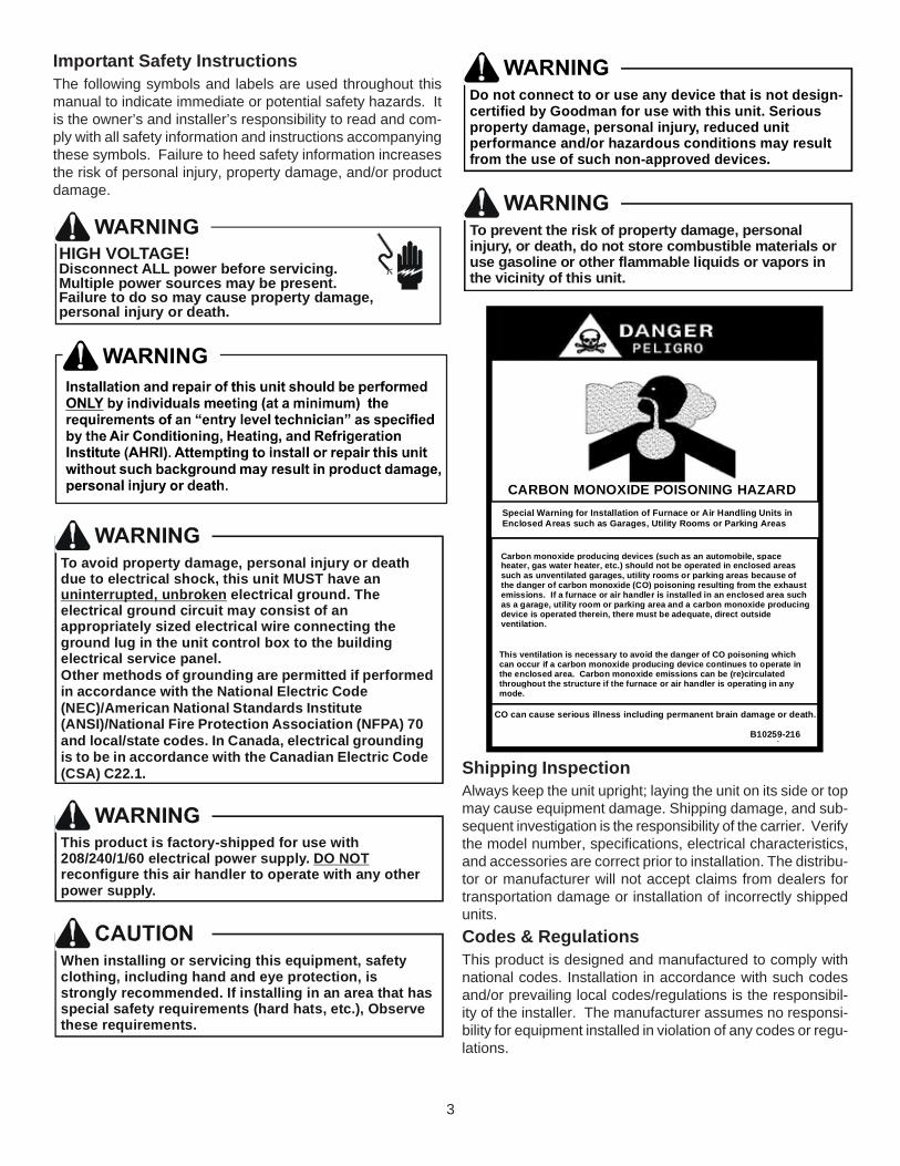
CARBON MONOXIDE POISONING HAZARD
-
Special Warning for Installation of Furnace or Air Handling Units inEnclosed Areas such as Garages, Utility Rooms or Parking Areas
Carbon monoxide producing devices (such as an automobile, spaceheater, gas water heater, etc.) should not be operated in enclosed areassuch as unventilated garages, utility rooms or parking areas because ofthe danger of carbon monoxide (CO) poisoning resulting from the exhaustemissions. If a furnace or air handler is installed in an enclosed area suchas a garage, utility room or parking area and a carbon monoxide producingdevice is operated therein, there must be adequate, direct outsideventilation.
This ventilation is necessary to avoid the danger of CO poisoning whichcan occur if a carbon monoxide producing device continues to operate inthe enclosed area. Carbon monoxide emissions can be (re)circulatedthroughout the structure if the furnace or air handler is operating in anymode.
CO can cause serious illness including permanent brain damage or death.
B10259-216
Shipping InspectionAlways keep the unit upright; laying the unit on its side or topmay cause equipment damage. Shipping damage, and sub-sequent investigation is the responsibility of the carrier. Verifythe model number, specifications, electrical characteristics,and accessories are correct prior to installation. The distribu-tor or manufacturer will not accept claims from dealers fortransportation damage or installation of incorrectly shippedunits.Codes & RegulationsThis product is designed and manufactured to comply withnational codes. Installation in accordance with such codesand/or prevailing local codes/regulations is the responsibil-ity of the installer. The manufacturer assumes no responsi-bility for equipment installed in violation of any codes or regu-lations.

4
The United States Environmental Protection Agency(EPA) has issued various regulations regarding the in-troduction and disposal of refrigerants. Failure to followthese regulations may harm the environment and can leadto the imposition of substantial fines. Should you haveany questions please contact the local office of the EPA.Replacement PartsWhen reporting shortages or damages, or ordering repairparts, give the complete product model and serial numbersas stamped on the product. Replacement parts for this prod-uct are available through your contractor or local distributor.For the location of your nearest distributor consult the whitebusiness pages, the yellow page section of the local tele-phone book or contact:
CONSUMER AFFAIRSGOODMAN MANUFACTURING COMPANY, L.P.
7401 SECURITY WAYHOUSTON, TEXAS 77040
(877) 254-4729If replacing an air handler, the system must be manufacturerapproved and Air Conditioning, Heating, and RefrigerationInstitute (AHRI) matched. NOTE: Installation of unmatchedsystems is strongly discouraged.
Pre-Installation InstructionsCarefully read all instructions for the installation prior to in-stalling product. Make sure each step or procedure is under-stood and any special considerations are taken into accountbefore starting installation. Assemble all tools, hardwareand supplies needed to complete the installation. Some itemsmay need to be purchased locally. Make sure everythingneeded to install the product is on hand before starting.LocationNOTE: Air handlers are designed for indoor installationonly.Give special consideration to minimizing the length of refrig-erant tubing when installing air handlers. Refer to RemoteCooling/Heat Pump Service Manual, TP-106 Long Line SetApplication R-22 or TP-107 Long Line Set Application R-410Afor guidelines. The unit clearance from a combustible sur-face may be 0". However, service clearance is to take prece-dence. In addition allow a minimum of 24" in front of the unitfor service clearance.If the unit is located in an area with high ambient temperatureand/or high humidity, the air handler may be subject to nui-sance sweating of the casing. On these installations, a wrapof 2” fiberglass insulation with a vapor barrier is recom-mended.Do not install the air handler in a location that violates theinstructions provided with the condenser.Consult all appropriate regulatory codes prior to determiningfinal clearances. When installing this unit in an area that maybecome wet, elevate the unit with a sturdy, non-porous ma-terial. In installations that may lead to physical damage (i.e. agarage) it is advised to install a protective barrier to preventsuch damage.
DuctworkThis air handler is designed for a complete supply and returnductwork system.
Do not operate this product without all the ductwork attached.
To ensure correct system performance, the ductwork is to besized to accommodate 375-425 CFM per ton of cooling withthe static pressure not to exceed .5" WC. Inadequate ductwork that restricts airflow can result in improper performanceand compressor or heater failure. Ductwork is to be con-structed in a manner that limits restrictions and maintainssuitable air velocity. Ductwork is to be sealed to the unit in amanner that will prevent leakage.
Return DuctworkDO NOT TERMINATE THE RETURN DUCTWORK IN ANAREA THAT CAN INTRODUCE TOXIC, OR OBJECTION-ABLE FUMES/ODORS INTO THE DUCTWORK. The returnductwork is to be introduced into the air handler bottom (upflowconfiguration).
Return Air FiltersEach installation must include a return air filter. This filteringmay be performed at the air handler or externally such as areturn air filter grille. Air handlers mounted in the downfloworientation, including “B” series, require external filtering. Awashable filter is available as an accessory. To ensure opti-mum performance frequent filter cleaning is advised. Referto Table 1 for the appropriate filter.
AEPF Filter Number Qty Required
303631374260
1
N/A FIL 18-32
FIL 48-61
1
1830 FIL 36-42 1
Table 1
Electric HeatRefer to this manual in combination with the instructions pro-vided with the heat kit for the correct installation procedure.The air handlers listed in this manual do not have factoryinstalled electric heat. Electric heat is available as an acces-sory. If installing this option, the ONLY heat kits that can beused are the HKR series.
NOTE: The Amana® brand EHK, ECB, EDB, and EDK kitsare NOT approved for use with these air handlers.The heating mode temperature rise is dependent upon thesystem airflow, the supply voltage, and the heat kit size (kW)selected. Use Tables 2, 3, and 4 to determine the tempera-ture rise (ºF).
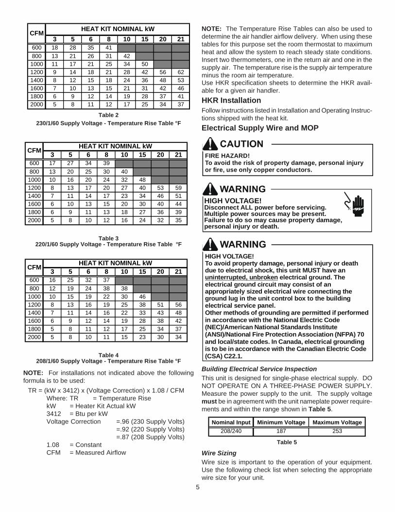
5
3 5 6 8 10 15 20 21600 18 28 35 41800 13 21 26 31 42
1000 11 17 21 25 34 501200 9 14 18 21 28 42 56 621400 8 12 15 18 24 36 48 531600 7 10 13 15 21 31 42 461800 6 9 12 14 19 28 37 412000 5 8 11 12 17 25 34 37
HEAT KIT NOMINAL kWCFM
Table 2230/1/60 Supply Voltage - Temperature Rise Table °F
3 5 6 8 10 15 20 21600 17 27 34 39800 13 20 25 30 40
1000 10 16 20 24 32 481200 8 13 17 20 27 40 53 591400 7 11 14 17 23 34 46 511600 6 10 13 15 20 30 40 441800 6 9 11 13 18 27 36 392000 5 8 10 12 16 24 32 35
CFM HEAT KIT NOMINAL kW
Table 3220/1/60 Supply Voltage - Temperature Rise Table °F
3 5 6 8 10 15 20 21600 16 25 32 37800 12 19 24 38 38
1000 10 15 19 22 30 461200 8 13 16 19 25 38 51 561400 7 11 14 16 22 33 43 481600 6 9 12 14 19 28 38 421800 5 8 11 12 17 25 34 372000 5 8 10 11 15 23 30 34
CFM HEAT KIT NOMINAL kW
Table 4208/1/60 Supply Voltage - Temperature Rise Table °F
NOTE: For installations not indicated above the followingformula is to be used:
TR = (kW x 3412) x (Voltage Correction) x 1.08 / CFMWhere: TR = Temperature RisekW = Heater Kit Actual kW3412 = Btu per kWVoltage Correction =.96 (230 Supply Volts)
=.92 (220 Supply Volts)=.87 (208 Supply Volts)
1.08 = ConstantCFM = Measured Airflow
NOTE: The Temperature Rise Tables can also be used todetermine the air handler airflow delivery. When using thesetables for this purpose set the room thermostat to maximumheat and allow the system to reach steady state conditions.Insert two thermometers, one in the return air and one in thesupply air. The temperature rise is the supply air temperatureminus the room air temperature.Use HKR specification sheets to determine the HKR avail-able for a given air handler.HKR InstallationFollow instructions listed in Installation and Operating Instruc-tions shipped with the heat kit.Electrical Supply Wire and MOP
FIRE HAZARD!To avoid the risk of property damage, personal injury or fire, use only copper conductors.
HIGH VOLTAGE!
Failure to do so may cause property damage,personal injury or death.
Disconnect ALL power before servicing.Multiple power sources may be present.
HIGH VOLTAGE!To avoid property damage, personal injury or death due to electrical shock, this unit MUST have an
electrical ground. The electrical ground circuit may consist of an appropriately sized electrical wire connecting the ground lug in the unit control box to the building electrical service panel.Other methods of grounding are permitted if performed in accordance with the National Electric Code (NEC)/American National Standards Institute (ANSI)/National Fire Protection Association (NFPA) 70 and local/state codes. In Canada, electrical grounding is to be in accordance with the Canadian Electric Code (CSA) C22.1.
uninterrupted, unbroken
Building Electrical Service InspectionThis unit is designed for single-phase electrical supply. DONOT OPERATE ON A THREE-PHASE POWER SUPPLY.Measure the power supply to the unit. The supply voltagemust be in agreement with the unit nameplate power require-ments and within the range shown in Table 5.
Nominal Input Minimum Voltage Maximum Voltage208/240 187 253
Table 5
Wire SizingWire size is important to the operation of your equipment.Use the following check list when selecting the appropriatewire size for your unit.

6
• Wire size must carry the Minimum Circuit Ampac-ity (MCA).
• Refer to the NEC (USA) or CSA (Canada) for wire siz-ing. The unit MCA for the air handler and the optionalelectric heat kit can be found on the unit Series andRating Plate.
• Wire size allows for no more than a 2% voltage dropfrom the building breaker/fuse panel to the unit.
Refer to the latest edition of the National Electric Codeor in Canada the Canadian Electric Code when deter-mining the correct wire size. The following table showsthe current carrying capabilities for copper conductorsrated at 75oC with a 2% voltage drop. Use Table 6 todetermine the voltage drop per foot of various conduc-tors.
10 15 20 25 30 35 40 4514 75 50 37 NR NR NR NR NR12 118 79 59 47 NR NR NR NR10 188 125 95 75 63 54 NR NR8 301 201 150 120 100 86 75 686 471 314 235 188 157 134 118 110
*Based on NEC 1996
Maximum Allowable Length in Feetto Limit Voltage Drop to 2%*
Minimum Circuit Ampacity (MCA) Wire Size(AWG)
Table 6
Maximum Overcurrent Protection (MOP)Every installation must include an NEC (USA) or CEC(Canada) approved overcurrent protection device. Also,check with local or state codes for any special regional re-quirements.Protection can be in the form of fusing or HACR style circuitbreakers. The Series and Rating Plate can be used as aguide for selecting the MAXIMUM overcurrent device.
NOTE: Fuses or circuit breakers are to be sized largerthan the equipment MCA but not to exceed the MOP.
Electrical Connections – Supply VoltageUSE COPPER CONDUCTORS ONLY.A knockout is provided on the air handler top panel or side toallow for the entry of the supply voltage conductors. If theknockouts on the cabinet sides are used for electrical con-duit, an adapter ring must be used in order to meet UL1995safety requirements. An NEC or CEC approved strain reliefis to be used at this entry point. The wire is to be sized inaccordance with the “Electrical Wire and MOP” section ofthis manual. Some areas require the supply wire to be en-closed in conduit. Consult your local codes.
Air Handler Only (Non-Heat Kit Models)The building supply connects to the stripped black and redwires contained in the air handler electrical compartment cav-
ity. A ground screw is also contained in this area. Attach thesupply wires to the air handler conductors as shown in theunit wiring diagram using appropriately sized solderless con-nectors or other NEC or CEC approved means.
Air Handler With Non-Circuit Breaker Heat KitsA terminal block is provided with the HKR kit to attach thepower supply and air handler connections. Follow the HKRInstallation Manual and wiring diagram for complete wiringdetails.
Air Handler With Heat Kits Containing a Circuit BreakerHKR models with a “C” suffix contain a circuit breaker(s).The air handler has a plastic cover on the access panel thatwill require either one or both sections to be removed to al-low the heat kit circuit breaker(s) to be installed. See theHKR Installation Instructions for further details. The air han-dler wires and supply wires are installed directly onto the HKRcircuit breaker(s) as shown in the HKR Installation Manualand wiring diagram.
Low Voltage ConnectionsSeveral combinations of low voltage schemes are available,depending on the presence of a heat kit and whether theheat kit is single-stage or multi-staging. The low voltage con-nections are determined by whether the outdoor unit is a con-denser or heat pump. The 24V-control voltage connects theair handler to the room thermostat and condenser. Low volt-age wiring is to be copper conductors. A minimum of 18AWGmust be used for installations up to 50’ and 16AWG for in-stallations over 50’. Low voltage wiring can be connectedthrough the top of the cabinet or either side. See the “Ther-mostat Wiring” section of this manual for typical low voltagewiring connections.Refrigerant Lines
This product is factory-shipped under pressure. Follow these instructions to prevent injury.
A quenching cloth is strongly recommended to prevent scorching or marring of the equipment finish when welding close to the painted surfaces. Use brazing alloy of 5% minimum silver content.
Tubing PreparationAll cut ends are to be round, burr free, and clean. Failureto follow this practice increases the chances for refrigerantleaks. The suction line is spun closed and requires pipecutters to remove the closed end.
Post BrazingQuench all welded joints with water or a wet rag.Piping SizeFor the correct tubing size, follow the specification for thecondenser/heat pump.

7
Special InstructionsThis coil comes equipped with a check style flowrator forrefrigerant management. For most installations with match-ing applications, no change to the flowrator piston is required.However, in mix-matched applications, a flowrator pistonchange may be required. See the Goodman® piston kit chartor consult your local distributor for details regarding mix-matched piston sizing. If the mix-match application requiresa different piston size, change the piston in the flowrator onthe indoor coil before installing the coil and follow the proce-dure shown below.
IMPORTANT NOTE: Torch heat required to braze tubes ofvarious sizes is proportional to the size of the tube. Tubes ofsmaller size require less heat to bring the tube to brazingtemperature before adding brazing alloy. Applying too muchheat to any tube can melt the tube. Service personnel mustuse the appropriate heat level for the size of the tube beingbrazed.NOTE: The use of a heat shield when brazing is recommendedto avoid burning the serial plate or the finish on the unit. Heattrap or wet rags should be used to protect heat sensitivecomponents such as service valves and TXV valves.
1. Loosen the 13/16 nut 1 TURN ONLY to allow high pres-sure tracer gas to escape. No gas indicates a possibleleak.
2. After the gas has escaped, remove the nut and discardthe black or brass cap.
3. Remove the check piston to verify it is correct and thenreplace the piston. See piston kit chart in instructions.
4. Use a tube cutter to remove the spin closure on thesuction line.
5. Remove the tailpiece clamped to the exterior and slidethe 13/16 nut into place.
6. Braze tailpiece to the line set liquid tube.
WHITETEFLON SEAL
PISTON
TAILPIECE
13/16” NUT
PLASTIC or BRASS CAP
Figure 17. Insert the suction line into the connection, slide the in-
sulation and the rubber grommet at least 18" away fromthe braze joint. Braze suction line.
8. AFTER THE TAILPIECE HAS COOLED, confirm posi-tion of the white Teflon® seal and hand tighten the 13/16”nut.
9. Torque the 13/16” nut to 7-25 ft-lbs. or tighten 1/6 turn.
Excessive torque can cause orifices to stick. Use the proper torque settings when tightening orifices.
10. Replace suction line grommet and insulation.
RUBBERGROMMET
SUCTION LINEWITH SPIN CLOSURE
Figure 2Downflow ConversionConversion to downflow MUST be performed in an area thatallows access to all sides prior to placing the air handler in itsfinal location. To prevent the evaporator coil pan from “sweat-ing” the DPI accessory insulation kit is to be used when per-forming this conversion. NOTE: The DPI kit is not suppliedwith this product and is to be purchased separately. SeeTable 7 for the correct DPI kit.
AEPF Model Insulation Kit
3036
3137
4260
N/A DPI18-30/20
1830
DPI48-61/-20
DPI36-42/20
Table 7Refer to Figures 3 through 5 for the location of the compo-nents referenced in the following steps. Figure 3 illustratesthe new installation location for the removed components.
1. Before inverting the air handler, remove all access pan-els, the coil rear channel bracket, and the filter close-offpanel.
2. Remove the evaporator coil and the horizontal drain pan.Discard horizontal drain pan.
3. Install the provided plastic plug into the vacated accesspanel.
4. Remove the two (2) zee coil support brackets and insu-lation retaining brackets.
5. Remove the tie bracket.
6. Install the DPI Insulation Kit onto the bottom of the drainpan.

8
NOTE: The filter provision is not applicablein THIS downflow application.
ACCESSPANEL
RETURN AIR SIDEOF UNIT
REAR CHANNELBRACKET
ZEE COILSUPPORT BRACKET
COIL RETAININGBRACKET
TIE BRACKET
Figure 3
7. Install the zee coil supports and the wrapper stiffeners.
8. Install the tie bracket.
9. Install the rear channel bracket.
10. To prevent possible condensate “blow off” the insula-tion retainers are to be laid into the evaporator coil panas shown in Figure 4.
3” FLAT INSULATIONRETAINER (BOTH SIDES)
Figure 4To complete the conversion, slide the evaporator coil intothe chassis and attach the three (3) access panels. (Figure5).
WRAPPER
INSULATIONJACKET
ZEE COILSUPPORT
WRAPPERSTIFFENER
DRAIN PANINSULATION KIT
BLOWERASSEMBLY
Figure 5
NOTE: When converted to downflow position the coil mayprotrude above the cabinet on some models.
Horizontal ConversionDedicated Downflow models are not suitable for horizontalapplication and must not be used for this type of installation.The only field modification required for conversion to “Hori-zontal Right-Hand” is the removal of the plastic knockouts inthe horizontal panel drain connections. To prevent the hori-zontal drain pan from sweating in high humidity applications,it is recommended that a DPIH insulation accessory kit beused. NOTE: The DPIH insulation kit is not supplied with thisproduct and should be purchased separately. See Table 8for the correct DPIH kit.
AEPF Model Insulation Kit
3036
3137
4260
DPIH48-61
N/A DPIH18-32
1830 DPIH36-42
Table 8
The following describes converting to “Horizontal Left-Hand”.Conversion to downflow MUST be performed in an area thatallows access to all sides prior to placing the air handler in itsfinal location (See Figure 6).
PRIMARYDRAIN
SECONDARYDRAIN
DPIH KIT
Figure 6
1. Remove the (3) air handler access panels.
2. Remove the “J” shaped bracket that retains the evapo-rator coil.
3. Remove the flowrator from the lower left side accesspanel and slide out the evaporator coil and horizontaldrain pan.
4. Remove the gasket from the horizontal pan drain con-nections.
5. Remove the oval shaped plastic plug from the left sideaccess panel. Remove the oval shaped rubber gasketseal from the lower right side access panel.

9
6. The drain connections for the horizontal pan are sealedwith a thin coating of plastic. Carefully knock out thisplastic seal with a screwdriver and hammer. Note: Theupper drain will become the secondary drain whichis mandatory in many municipalities .
7. Install the plastic plug removed in step 5 to the rightside lower access panel and the oval shaped rubbergasket to the lower left access panel.
8. Reinstall the evaporator coil with the horizontal panelon the left side. Note: Push the assembly completely tothe rear to ensure the engagement of the upflow panwith the rear channel bracket.
9. Install the “J” bracket (removed in step 2) to support theupflow pan to the tie channel.
10. Attach all panels and the metering device.
AEPF MOTOR ORIENTATIONIf the unit is in the upflow position, there is no need to rotatethe motor. If the unit is in the downflow position, loosen mo-tor mount and rotate motor as shown in Figure 7. Be suremotor is oriented with the female connections on the casingdown. If the motor is not oriented with the connections down,water will collect in the motor and may cause premature fail-ure.
FEMALECONNECTIONS
Figure 7(AEPF Motor Orientation)
Condensate RemovalThe coil drain pan has a primary and a secondary drain with3/4" NPT female connections. The connectors required are3/4" NPT male, either PVC or metal pipe, and should be handtightened to a torque of approximately 37 in-lbs. to preventdamage to the drain pan connection. An insertion depth be-tween .355 to .485 inches (3-5 turns) should be expected atthis torque. Use the female (3/4 NPT) threaded fitting thatprotrudes outside of the enclosure for external connections.
1. Ensure drain pan hole is NOT obstructed.
2. To prevent potential sweating and dripping on to finishedspace, it may be necessary to insulate the condensatedrain line located inside the building. Use Armaflex® orsimilar material.
A Secondary Condensate Drain Connection has been pro-vided for areas where the building codes require it. Pitch thedrain line 1/4" per foot to provide free drainage. Insulate drainlines located inside the building to prevent sweating. Install acondensate trap to ensure proper drainage. If the secondarydrain line is required, run the line separately from the primarydrain and end it where it can be easily seen.NOTE: Water coming from this line means the coil primarydrain is plugged and needs clearing.
CAUTIONIf secondary drain is not installed, the secondaryaccess must be plugged.
The installation must include a “P” style trap that is locatedas close as is practical to the evaporator coil. See Figure 7for details of a typical condensate line “P” trap.NOTE: Trapped lines are required by many local codes. Inthe absence of any prevailing local codes, please refer to therequirements listed in the Uniform Mechanical Building Code.A drain trap in a draw-through application prevents air frombeing drawn back through the drain line during fan operationthus preventing condensate from draining, and if connectedto a sewer line to prevent sewer gases from being drawn intothe airstream during blower operation.Field experience has shown condensate drain traps with anopen vertical Tee between the air handler and the conden-sate drain trap can improve condensate drainage in someapplications,but may cause excessive air discharge out ofthe open Tee. Goodman® does not prohibit this type of drainbut we also do not recommend it due to the resulting air leak-age. Regardless of the condensate drain design used, it isthe installer’s responsibility to ensure the condensate drainsystem is of sufficient design to ensure proper condensateremoval from the coil drain pan.
Air Handler
3" MIN.POSITIVE LIQUIDSEAL REQUIRED
AT TRAP
DrainConnection
2" MIN.
Figure 8Use of a condensate removal pump is permitted when nec-essary. This condensate pump should have provisions forshutting off the control voltage should a blocked drain occur.A trap must be installed between the unit and the conden-sate pump.
IMPORTANT NOTE: The evaporator coil is coated with oilsthat may dissolve styrofoam and certain types of plastics.Therefore, a removal pump or float switch must not containany of these materials.

10
Tip: Priming the “P” trap may avoid improper draining at theinitial installation and at the beginning of the cooling season.When coils are installed above ceilings, or in other locationswhere damage from condensate overflow may occur, it isMANDATORY to install a field fabricated auxiliary drain panunder the coil cabinet enclosure. Drain lines from the auxil-iary pan must be installed and terminated so that the home-owner can see water discharges.
ACHIEVING 2% LOW LEAKAGE RATEEnsure that the Neoprene gasket with PSA remains intact onall surfaces that the access panels are secured to. Thesesurfaces are the entire length of the wrapper and areas be-tween the upper tie plate, upper and lower access panels.Be sure that upper access panel breaker insert gasket is in-tact and also flowrator gasket is installed on the lower ac-cess panel. An additional drain hole cover is required.
AEPF MotorThis section references the operation characteristics of theAEPF model motor only. The ECM control board is factoryset with dipswitch #4 in the “ON” position and all otherdipswitches in the “OFF” position. For most applicationsthis setting is to be changed according to the electricheat size and the outdoor unit selection.The AEPF product uses a General Electric ECMTM motor.This motor provides many features not available on the tradi-tional PSC motor. These features include:• Improved Efficiency• Constant CFM• Soft Start and Stop• Improved Humidity ControlMotor Speed AdjustmentEach ECMTM blower motor has been preprogrammed for op-eration at 4 distinct airflow levels when operating in Cooling,H.P. Heating, Backup Heating (Electric Heating), and Backup+ H.P. Heating. Each mode has 4 levels to deliver differentAir Flow CFM [L/s]. The adjustment is performed by chang-ing the dipswitch(es) either to an “OFF” or “ON” position.
Dipswitch FunctionsThe AEPF air handler motor has an electronic control thatcontains an eight (8) position dip switch. The function of thesedipswitches are shown in Table 9.
Dipswitch Number Function
123 N/A4 Indoor Thermostat5678
Cooling & Heat Pump CFM
CFM Trim Adjust
Electric Heat
Table 9
CFM DeliveryTables 10-Electric Heat and 11-Cooling/Heat Pump showthe CFM output for dipswitch combinations 1-2, and 5-6.
1 2 7 8
OFF OFF OFF OFF 1100 1210ON OFF OFF OFF 890 935
OFF ON OFF OFF 700 770OFF OFF OFF OFF 2050 2150
AEPF3036 ON OFF OFF OFF 1750 1835
AEPF3137 OFF ON OFF OFF 1600 1680
AEPF4260 ON ON OFF OFF 1200 1260ON ON OFF ON 1020 1070
Model
AEPF1830
Emergecny (Electric)
Heat
Heat Pump w/Backup
Heat
SwitchSwitch
Table 10
5 6 7 8
OFF OFF OFF OFF 2 ½ 1100ON OFF OFF OFF 2 800
OFF ON OFF OFF 1 ½ 600OFF OFF OFF OFF 5 1800
AEPF3036 ON OFF OFF OFF 4 1580AEPF3137 OFF ON OFF OFF 3 ½ 1480
AEPF4260 ON ON OFF OFF 3 1200ON ON OFF ON 2 ½ 1020
Nominal CoolingTonnage
AEPF1830
Model CFMSwitchSwitch
Table 11
Thermostat “Fan Only Mode”During “Fan Only Mode” operation, the CFM output is 30% ofthe cooling setting.
CFM Trim AdjustMinor adjustments can be made through the dip switch com-bination of 7-8. The following Table 12 shows the switchposition for this feature.
CFM Switch 7 Switch 8+10% ON OFF-15% OFF ON
Table 12
Humidity ControlWhen using a Humidistat (normally closed), cut jumper PJ6on the control board. The Humidistat will only affect coolingairflow by adjusting the Airflow to 85%.
Two Stage HeatingWhen using staged electric heat, cut jumper PJ4 on the con-trol board.

11
ThermostatsNOTE: Second Stage heat can be accomplished by multi-stage heating thermostat or the addition of an outdoorthermostat as shown in Figures 9 and 10.Goodman® part number CHT18-60 is a single-stage cool andsingle-stage heat thermostat.Goodman® part number HPT18-60 is a single-stage cool,two-stage heat pump thermostat. The first stage is heat pumpheating and the second stage is optional electric heat.If additional features are desired, such as digital or program-mable capabilities, these thermostats are commercially avail-able. Follow the thermostat manufacturer’s instruction for in-stallation.
Start-Up Procedure• Prior to start-up, ensure that all electrical connections
are properly sized and tightened.
• All panels must be in place and secured. For Air Tightapplication, neoprene gasket must be positioned at pre-scribed locations to achieve 2% leakage.
• Tubing must be leak free.
• Unit should be elevated, trapped and pitched to allowfor drainage.
• Low voltage wiring is connected.
• Auxiliary drain is installed when necessary and pitchedto allow for drainage.
• Drain pan and drain tubing has been leak checked.
• Return and supply ducts are sealed.
• Unit is elevated when installed in a garage or whereflammable vapors may be present.
• Unit is protected from vehicular or other physical dam-age.
• Return air is not obtained from any areas where theremay be objectionable odors, flammable vapors or prod-ucts of combustion such as carbon monoxide (CO),which may cause serious personal injury or death.
Regular Maintenance
HIGH VOLTAGE!Disconnect ALL power before servicing or installing this unit. Multiple power sources may be present. Failure to do so may cause property damage, personal injury or death.
The only item to be maintained on a regular basis by the useris the circulating air filter(s). Filter should be cleaned or re-placed regularly. A certified service technician must performall other services.
NOTE: THESE INSTRUCTIONS ARE SPECIFICALLY FORAEPF MODELS. DO NOT USE THESE DIAGRAMS FOR ANYOTHER MODELS. SEE SEPARATE INSTALLATION ANDOPERATING INSTRUCTIONS FOR ATUF, ARUF, ARPT,ADPF, AND ASPF MODELS.
NOTICE: THIS PRODUCT CONTAINS ELECTRONICCOMPONENTS WHICH REQUIRE A DEFINITEGROUND. PROVISIONS ARE MADE FOR CONNEC-TION OF THE GROUND. A DEDICATED GROUNDFROM THE MAIN POWER SUPPLY OR AN EARTHGROUND MUST BE PROVIDED.
THERMOSTAT CONNECTIONSThe following composite wiring diagrams detail various con-figurations in which the AEPF air handlers can be used. Ex-amples include single-stage cooling and heat pump with singleor two-stage electric heating. All these configurations canbe applied with convenient connections to outdoor thermo-stat applications.The following sections will be detailed:
• Single-Stage Cooling (GMC Thermostat Part #CHT18-60 or equivalent.)
• Heat Pump (GMC Thermostat Part #18-60 or equiva-lent)
Each diagram details the connections between room ther-mostat and AEPF air handlers, and the connections betweenthe AEPF air handlers and the Condensing Unit (or HeatPump) with optional connections to Outdoor Thermostats.For each configuration, refer to the explanation of the properjumper(s) to remove for the corresponding blower speed thatwill result in the programmed ECM™ motor.
IMPORTANT: WHEN MATCHING THE AEPF AIRHANDLER TO A SINGLE SPEED COOLING UNIT ORHEAT PUMP REMEMBER TO CONNECT THE “Y”FROM THE THERMOSTAT TO THE “Y/Y2” CONNEC-TION ON THE VARIABLE SPEED BOARD (VSTB) OFTHE AIR HANDLER. CONNECTING TO “Y1” WILLRESULT IN FIRST STAGE COOLING BLOWERSPEED AND MAY CAUSE THE CONTACTOR TOCHATTER.
An equivalent thermostat can be used in place of theGoodman thermostat part number. The GMC thermostatslisted are mercury type thermostats.

12Wiring is subject to change, always refer to the wiring diagram on the unit for the most up-to-date wiring.
HIGH VOLTAGE! DISCONNECT ALL POWER BEFORE SERVICING.MULTIPLE POWER SOURCES MAY BE PRESENT. FAILURE TO DO SOMAY CAUSE PROPERTY DAMAGE, PERSONAL INJURY OR DEATH.
WARNING
COOLING ONLY - 2 STAGE HEAT (1st ROOM T'STAT & 2nd OT)
ROOMTHERMOSTAT
W C R G Y
OT2OT1 Y1W/W2E\W1 O OTC
CONFIGURATION.DIP SWITCHFOR PROPERTO MANUALPLEASE REFER
CONDENSERYCON
DIP
(CFM)
ON
OFF
OUTDOOR
W1
HUM
OT2
OT1W2
HEATPUMPCOM O W2 ED
SWIT
CH
HEATERW1 W2
24 VAC
CONDENSINGUNIT
THERMOSTATS
IF N
EED
ED
HUMG Y/Y2
Y1
HUMIDISTAT(OPTIONAL)
HUMIDISTAT
NOTES:1.) Y/Y2 ENABLES HI SPD FAN COOLING
2.) E/W1 ENABLES LO SPD FAN HEATING E/W1 WITH OT CLOSED ENABLES HI SPD FAN HEATING 3.) OT1 PJ4 MUST BE CUT FOR THIS CONFIGURATION
4.) DIP SWITCH #4 MUST BE IN THE "ON" POSITION. 5.) CUT HUM PJ6 JUMPER IF USING HUMIDISTAT. STAT OPENS ON HUMIDITY RISE.
FOR HEAT PUMPUSE ONLY
O
SINGLE STAGE COOLING WITH SINGLE OR TWO-STAGE HEATING
COOLING ONLY - 2 STAGE HEAT THERMOSTAT
NOTES:1.) Y/Y2 ENABLES HI SPD FAN COOLING
2.) E/W1 ENABLES LO SPD FAN HEATING W/W2 ENABLES HI SPD FAN HEATING 3.) OT1 PJ4 MUST BE CUT FOR THIS CONFIGURATION
OTCO RCE\W1 W/W2 Y1OT1 OT2
YCON
PLEASE REFERTO MANUALFOR PROPERDIP SWITCHCONFIGURATION.
R
DIP
(CFM)
ON
OFF
OUTDOOR
W1
HUM
OT2
OT1W2
HEATPUMPCOM O W2 ED
SW
ITC
H
HEATERW1 W2
24 VACC R
CONDENSINGUNIT
THERMOSTATS
IF N
EE
DED
Y/Y2G HUM
Y1
HUMIDISTAT(OPTIONAL)
HUMIDISTAT
ROOMTHERMOSTAT
W2 C R G YW1
4.) DIP SWITCH #4 MUST BE IN THE "ON" POSITION. 5.) CUT HUM PJ6 JUMPER IF USING HUMIDISTAT. STAT OPENS ON HUMIDITY RISE.
FOR HEAT PUMPUSE ONLY
O
FIGURE 9
FIGURE 10

13
HIGH VOLTAGE! DISCONNECT ALL POWER BEFORE SERVICING.MULTIPLE POWER SOURCES MAY BE PRESENT. FAILURE TO DO SOMAY CAUSE PROPERTY DAMAGE, PERSONAL INJURY OR DEATH.
WARNING
Wiring is subject to change, always refer to the wiring diagram on the unit for the most up-to-date wiring.
HEAT PUMP WITH SINGLE OR TWO-STAGE HEATING (OPTIONS FOR EMERGENCY HEAT)
COOLING ONLY - 2 STAGE HEAT (T'STAT ENABLED OT)
NOTES:1.) Y/Y2 ENABLES HI SPD FAN COOLING
2.) E/W1 ENABLES LO SPD FAN HEATING W/W2 WITH OT CLOSED ENABLES HI SPD FAN HEATING 3.) OT1 PJ4 MUST BE CUT FOR THIS CONFIGURATION OT2 PJ2 MUST BE CUT FOR THIS CONFIGURATION
OT2
PLEASE REFERTO MANUALFOR PROPERDIP SWITCHCONFIGURATION.
(CFM)
HUM
ON
DIP
OFF
YCONCONDENSER
E\W1
CONDENSINGUNIT
OUTDOOR
THERMOSTATS
HEATPUMP
W1OT1
COM O
W2
W2 ED
W/W2 O OTC OT1
W1 W2
SWIT
CH
HEATER 24 VAC
OT2 Y1
W1
IF N
EED
ED
THERMOSTATROOM
W2 C R G
HUMIDISTAT(OPTIONAL)
Y1
HUMHUMIDISTAT
Y/Y2G
Y
4.) DIP SWITCH #4 MUST BE IN THE "ON" POSITION. 5.) CUT HUM PJ6 JUMPER IF USING HUMIDISTAT. STAT OPENS ON HUMIDITY RISE.
FOR HEAT PUMPUSE ONLY
O
HEATPUMP - WITH 1 STG EMHT 1 STG AUX HEAT
NOTES:1.) Y ENABLES HI SPD FAN COOLING
2.) E AND W2 ENABLE HI SPD FAN HEATING 3.) IF OT2 PJ2 JUMPER IS CUT E AND W2 ENABLE LO SPD FAN HEATING
HUMIDISTAT(OPTIONAL)
IF N
EE
DE
D
OT2OT1 Y1W/W2E\W1 C RO OTC
CONFIGURATION.DIP SWITCHFOR PROPERTO MANUALPLEASE REFER
YCONR
DIP
(CFM)
ON
OFF
OUTDOOR
W1
HUM
OT2
OT1W2
HEATPUMPCOM O W2 ED
SW
ITC
H
HEATERW1 W2
24 VACC R
THERMOSTATSHUMG Y/Y2
Y1
HUMIDISTAT
ROOMTHERMOSTAT
E C R G Y
HEATPUMP
R Y C O W2
HEATPUMPYCONR COM O W2 ED
W2 O
4.) DIP SWITCH #4 MUST BE IN THE "ON" POSITION. 5.) CUT HUM PJ6 JUMPER IF USING HUMIDISTAT. STAT OPENS ON HUMIDITY RISE.
6.) REMOVE ORANGE JUMPER WIRE Y1-O.
REMOVEPRODUCTIONWIRE Y1-O

14Wiring is subject to change, always refer to the wiring diagram on the unit for the most up-to-date wiring.
HIGH VOLTAGE! DISCONNECT ALL POWER BEFORE SERVICING.MULTIPLE POWER SOURCES MAY BE PRESENT. FAILURE TO DO SOMAY CAUSE PROPERTY DAMAGE, PERSONAL INJURY OR DEATH.
WARNING
Y
ROOM
IF N
EE
DE
D
THERMOSTATS
THERMOSTATW2E O C R G
HUMIDISTAT(OPTIONAL)
HUMIDISTAT
HEATPUMP - 2 STG EMHT 1 STG AUX HEAT
NOTES:1.) Y ENABLES HI SPD FAN COOLING
2.) E ENABLES LO SPD FAN HEATING W2 ENABLES HI SPD FAN HEATING 3.) OT1 PJ4 MUST BE CUT FOR THIS CONFIGURATION
YCONR
R
HEATPUMPCOM O EDW2
CHEATPUMP
Y O W2
Y/Y2G HUMOTCO RCE\W1 W/W2 Y1OT1 OT2
Y1
DIP
TO MANUALFOR PROPERDIP SWITCHCONFIGURATION.
(CFM)
ON
OFF
HEATPUMP
W1
PLEASE REFER
HUM
OT2
OT1
YCONR COM O
W2HEATER
SW
ITC
HW2
W124 VAC
C R
W2 ED
OUTDOOR
4.) DIP SWITCH #4 MUST BE IN THE "ON" POSITION. 5.) CUT HUM PJ6 JUMPER IF USING HUMIDISTAT. STAT OPENS ON HUMIDITY RISE.
6.) REMOVE ORANGE JUMPER WIRE Y1-O.
REMOVEPRODUCTIONWIRE Y1-O
O
W2
DIP SWITCH
DIP
OFFON
2nd STAGE HEATER1st STAGE HEATER
O
E\W1 W/W2 O
SWIT
CH
IF N
EED
ED
W2
Y/Y2G
1st STAGE AUX HEAT ENABLED BY ROOM T'STAT2ND STAGE AUX ENABLED BY ROOM T'STAT AND OUTDOOR T'STAT
HEATPUMP - 2 STG EMHT 2 STG AUX - 1 OUTDOOR T'STAT
OUTDOORTHERMOSTAT
4.) DIP SWITCH #4 MUST BE IN THE "ON" POSITION.
5.) CUT HUM PJ6 JUMPER IF USING HUMIDISTAT. STAT OPENS ON HUMIDITY RISE.
6.) REMOVE ORANGE JUMPER WIRE Y1-O.
REMOVEPRODUCTIONWIRE Y1-O

15
HIGH VOLTAGE! DISCONNECT ALL POWER BEFORE SERVICING.MULTIPLE POWER SOURCES MAY BE PRESENT. FAILURE TO DO SOMAY CAUSE PROPERTY DAMAGE, PERSONAL INJURY OR DEATH.
WARNING
Wiring is subject to change, always refer to the wiring diagram on the unit for the most up-to-date wiring.
ROOMTHERMOSTAT
OT2THERMOSTATS
W1HEATER
OT1OW/W2E\W1 OTC
NOTES:1.) Y ENABLES HI SPD FAN COOLING
2.) E ENABLES LO SPD FAN HEATING W2 AND OT1 CLOSED ENABLES LO SPD FAN HEATING W2 AND OT2 CLOSED ENABLES HI SPD FAN HEATING 3.) OT1 PJ4 AND 0T2 PJ2 MUST BE CUT FOR THIS CONFIGURATION
PLEASE REFERTO MANUALFOR PROPERDIP SWITCHCONFIGURATION.
(CFM)
R
OT1
HUM
OT2
W2W1
HEATPUMPCOMYCON O EDW2
OUTDOOR
O
HEATPUMP
HEATPUMPR YCON OCOM
R Y C
W2 ED
W2 OE W2
HUMG Y/Y2Y1RC
DIP
ON
OFF
SWIT
CH
W224 VACC R
Y1
HUMIDISTAT
IF N
EED
ED
GC R Y
HUMIDISTAT(OPTIONAL)OT2
OUTDOOR
OT1OTC
HEATPUMP - 2 STG EMHT 2 STG AUX - 2 OUTDOOR T'STATS
4.) DIP SWITCH #4 MUST BE IN THE "ON" POSITION. 5.) CUT HUM PJ6 JUMPER IF USING HUMIDISTAT. STAT OPENS ON HUMIDITY RISE.
6.) REMOVE ORANGE JUMPER WIRE Y1-O.
REMOVEPRODUCTIONWIRE Y1-O
4.) DIP SWITCH #4 MUST BE IN THE "ON" POSITION. 5.) CUT HUM PJ6 JUMPER IF USING HUMIDISTAT. STAT OPENS ON HUMIDITY RISE.
6.) REMOVE ORANGE JUMPER WIRE Y1-O.
W1
W/W2E\W1
W2W1
W2
OR C
W2
O
ON
W2
GC R
REMOVEPRODUCTIONWIRE Y1-O

16Wiring is subject to change, always refer to the wiring diagram on the unit for the most up-to-date wiring.
HIGH VOLTAGE! DISCONNECT ALL POWER BEFORE SERVICING.MULTIPLE POWER SOURCES MAY BE PRESENT. FAILURE TO DO SOMAY CAUSE PROPERTY DAMAGE, PERSONAL INJURY OR DEATH.
WARNING
2 SPEED HEAT PUMP WITH SINGLE OR TWO STAGE HEATING(OPTIONS FOR EMERGENCY HEAT) WITH CONVENTIONAL TWO STAGE THERMOSTAT
J1
PN. B1368274
PJ6
PJ2
PJ4OT1
OT2
HUM
12
34
56
78W1 W2
COM W2
DIP
24 VACW2W1
OUTDOOR
HEATPUMP
J2J3
1
4
1
5
Y/Y2OT2 HUMHUMIDISTAT
OT1OTCW/W2E\W1THERMOSTATS
GOODMAN MFG. CO. L.P.
COM W2HEATPUMP
W2
HEATPUMPROOM
THERMOSTAT
W2
IF N
EE
DED
HUMIDISTAT(OPTIONAL)
SEE NOTE 4
2nd STAGE HEATER
NOTES:1.) Y ENABLES HI SPD FAN COOLING
2.) E ENABLES LO SPD FAN HEATING
4.) CUT HUM PJ6 JUMPER IF USING HUMIDISTAT STAT OPENS ON HUMIDITY RISE
5.) DIP SWITCH #4 MUST BE IN THE "OFF" POSITION
6.) REMOVE ORANGE JUMPER WIRE Y1-O.
HEATPUMP - WITH 1 STG EMHT 1 STG AUX HEAT
1ST STAGE HEATER
O
O REMOVEPRODUCTIONWIRE Y1-O
R YCON COM O W2 EDHEATPUMPCONDENSER
C O W2 W2E CY2R R Y2G
IF N
EED
ED
HEATPUMP - WITH 1 STG EMHT 1 STG AUX HEAT
Y1 Y1
J1
R1
R3
CR10
R2
CR9
PJ6
PJ2
PJ4OT1
OT2
HUM
12
34
56
78
PLEASE REFERTO MANUALFOR PROPERDIP SWITCHCONFIGURATION.
W1 W2
R YCON COM O W2 ED
SWITCH
DIP
ON
OFF
24 VACC R
Y1
W2W1
OUTDOOR
HEATPUMPCONDENSER
DS1
CR1
CR2CR5
CR6
CR7CR8CR3
CR11
J2J3
1
4
C2
1
5
Y1RC G Y/Y2OT2 HUMHUMIDISTAT
OT1OTCW/W2E\W1THERMOSTATS
O
O REMOVEPRODUCTIONWIRE Y1-O

17
HIGH VOLTAGE! DISCONNECT ALL POWER BEFORE SERVICING.MULTIPLE POWER SOURCES MAY BE PRESENT. FAILURE TO DO SOMAY CAUSE PROPERTY DAMAGE, PERSONAL INJURY OR DEATH.
WARNING
Wiring is subject to change, always refer to the wiring diagram on the unit for the most up-to-date wiring.
R YCON COM O W2 EDHEATPUMPCONDENSER
C O W2 W2E CY2R R Y2G
IF N
EED
ED
HEATPUMP - 2 STG EMHT 1 STG AUX HEAT
Y1 Y1
J1
R1
R3
CR10
R2
CR9
PJ6
PJ2
PJ4OT1
OT2
HUM
12
34
56
78
PLEASE REFERTO MANUALFOR PROPERDIP SWITCHCONFIGURATION.
W1 W2
R YCON COM O W2 ED
SWITCH
DIP
ON
OFF
24 VACC R
Y1
W2W1
OUTDOOR
HEATPUMPCONDENSER
DS
1 CR1
CR2CR5
CR6
CR7CR8
CR3
CR11
J2J3
1
4
C2
1
5
Y1RC G Y/Y2OT2 HUMHUMIDISTAT
OT1OTCW/W2E\W1THERMOSTATS
O
O REMOVEPRODUCTIONWIRE Y1-O
R YCON COM O W2 EDHEATPUMPCONDENSER
C O W2 W2E CY2R R Y2G
IF N
EED
ED
HEATPUMP - 2 STG EMHT 2 STG AUX - 1 OUTDOOR T'STAT
Y1 Y1O
J1
R1
R3
CR10
R2
CR9
PJ6
PJ2
PJ4OT1
OT2
HUM
12
34
56
78
PLEASE REFERTO MANUALFOR PROPERDIP SWITCHCONFIGURATION.
W1 W2
R YCON COM O W2 ED
SWITCH
DIP
ON
OFF
24 VACC R
Y1
W2W1
OUTDOOR
HEATPUMPCONDENSER
DS
1 CR1
CR2CR5
CR6
CR7CR8CR3
CR11
J2J3
1
4
C2
1
5
Y1RC G Y/Y2OT2 HUMHUMIDISTAT
OT1OTCW/W2E\W1THERMOSTATS
O REMOVEPRODUCTIONWIRE Y1-O

18Wiring is subject to change, always refer to the wiring diagram on the unit for the most up-to-date wiring.
HIGH VOLTAGE! DISCONNECT ALL POWER BEFORE SERVICING.MULTIPLE POWER SOURCES MAY BE PRESENT. FAILURE TO DO SOMAY CAUSE PROPERTY DAMAGE, PERSONAL INJURY OR DEATH.
WARNING
R YCON COM O W2 EDHEATPUMPCONDENSER
C O W2 W2E CY2R R Y2G
IF N
EED
ED
HEATPUMP - 2 STG EMHT 2 STG AUX - 2 OUTDOOR T'STATS
Y1 Y1O
J1
R1
R3
CR10
R2
CR9
PJ6
PJ2
PJ4OT1
OT2
HUM
12
34
56
78
PLEASE REFERTO MANUALFOR PROPERDIP SWITCHCONFIGURATION.
W1 W2
R YCON COM O W2 ED
SWITCH
DIP
ON
OFF
24 VACC R
Y1
W2W1
OUTDOOR
HEATPUMPCONDENSER
DS
1 CR1
CR2
CR5CR6
CR7CR8CR3
CR11
J2J3
1
4
C2
1
5
Y1RC G Y/Y2OT2 HUMHUMIDISTAT
OT1OTCW/W2E\W1THERMOSTATS
OT1 OT2OTC
OUTDOOR
O REMOVEPRODUCTIONWIRE Y1-O
R YCON COM O W2 EDHEATPUMPCONDENSER
C O W2 W2E CY2R R Y2G
IF N
EED
ED
HEATPUMP - 2 STG EMHT 1 STG AUX - 1 OUTDOOR T'STAT
Y1 Y1O
J1
R1
R3
CR10
R2
CR9
PJ6
PJ2
PJ4OT1
OT2
HUM
12
34
56
78
PLEASE REFERTO MANUALFOR PROPERDIP SWITCHCONFIGURATION.
W1 W2
R YCON COM O W2 ED
SWITCH
DIP
ON
OFF
24 VACC R
Y1
W2W1
OUTDOOR
HEATPUMPCONDENSER
DS1
CR1
CR2CR5
CR6
CR7CR8
CR3
CR11
J2J3
1
4
C2
1
5
Y1RC G Y/Y2OT2 HUMHUMIDISTAT
OT1OTCW/W2E\W1THERMOSTATS
O REMOVEPRODUCTIONWIRE Y1-O

19
HIGH VOLTAGE! DISCONNECT ALL POWER BEFORE SERVICING.MULTIPLE POWER SOURCES MAY BE PRESENT. FAILURE TO DO SOMAY CAUSE PROPERTY DAMAGE, PERSONAL INJURY OR DEATH.
WARNING
Wiring is subject to change, always refer to the wiring diagram on the unit for the most up-to-date wiring.
TWO-STAGE COOLING WITH CONVENTIONAL TWO-STAGE THERMOSTAT
2 SPD COOLING ONLY - WITH 1 STAGE ELECTRIC HEAT
NEEDED
OT2 OT1 Y1 W/W2 E W1 C R O OTC
CONFIGURATION. DIP SWITCH FOR PROPER TO MANUAL PLEASE REFER
CONDENSER YCON R
DIP
(CFM) ON O
FF
OUTDOOR
W1 HUM OT2 OT1 W2
HEATPUMP COM O W2 ED
SWITCH
HEATER W1 W2 24 VAC C R
THERMOSTATS HUM G Y/Y2
Y1
HUMIDISTAT
C
NOTES:1.) Y1 ENABLES LO SPD FAN COOLING Y/Y2 ENABLES HI SPD FAN COOLING
2.) E/W1 ENABLES HI SPD FAN HEATING
3.) IF OT1 PJ4 JUMPER IS CUT E/W1 ENABLES LOW SPD FAN HEATING
4.) CUT HUM PJ6 JUMPER IF USING HUMIDISTAT STAT OPENS ON HUMIDITY RISE
5.) DIP SWITCH #4 MUST BE IN THE “OFF” POSITION
2-SPDCONDENSING
UNIT
ROOMTHERMOSTAT
CW
HUMIDISTAT(OPTIONAL)
SEE NOTE 4
1st STAGE HEATER
FOR HEAT PUMPUSE ONLY
O
2 SPD COOLING ONLY - WITH 2 STAGE HEAT THERMOSTAT
IF
\
Y2
C
Y1
NOTES:1.) Y1 ENABLES LO SPD FAN COOLING Y/Y2 ENABLES HI SPD FAN COOLING
2.) E/W1 ENABLES HI SPD FAN HEATING
3.) IF OT1 PJ4 JUMPER IS CUT E/W1 ENABLES LOW SPD FAN HEATING
4.) CUT HUM PJ6 JUMPER IF USING HUMIDISTAT STAT OPENS ON HUMIDITY RISE
5.) DIP SWITCH #4 MUST BE IN THE “OFF” POSITION
2-SPDCONDENSING
UNIT
ROOMTHERMOSTAT
HUMIDISTAT(OPTIONAL)
SEE NOTE 4
1st STAGE HEATER
C W FOR HEAT PUMPUSE ONLY
O

20Wiring is subject to change, always refer to the wiring diagram on the unit for the most up-to-date wiring.
HIGH VOLTAGE! DISCONNECT ALL POWER BEFORE SERVICING.MULTIPLE POWER SOURCES MAY BE PRESENT. FAILURE TO DO SOMAY CAUSE PROPERTY DAMAGE, PERSONAL INJURY OR DEATH.
WARNING
-2 SPD COOLING ONLY WITH 2 STAGE HEAT THERMOSTAT
IF
\
Y2
C
Y1
2-SPDCONDENSING
UNIT
NOTES:1.) Y1 ENABLES LO SPD FAN COOLING Y/Y2 ENABLES HI SPD FAN COOLING
2.) E/W1 ENABLES HI SPD FAN HEATING
3.) IF OT1 PJ4 JUMPER IS CUT E/W1 ENABLES LOW SPD FAN HEATING
4.) CUT HUM PJ6 JUMPER IF USING HUMIDISTAT STAT OPENS ON HUMIDITY RISE
5.) DIP SWITCH #4 MUST BE IN THE “OFF” POSITION
C W
HUMIDISTAT(OPTIONAL)
SEE NOTE 4
1st STAGE HEATER
ROOMTHERMOSTAT
FOR HEAT PUMPUSE ONLY
O
OT2
PLEASE REFERTO MANUALFOR PROPERDIP SWITCHCONFIGURATION.
(CFM)
HUM
ON
DIP
OFF
YCONCONDENSER
R
E\W1
OUTDOOR
THERMOSTATS
HEATPUMP
W1OT1
COM O
W2
W2 ED
W/W2 O OTC OT1
W1 W2
SWIT
CH
HEATERC R24 VAC
OT2 C R Y1
IF N
EED
ED
Y1
HUMHUMIDISTAT
Y/Y2G
GW1 W2 RC Y1 Y2
2 SPD COOLING ONLY - 2 STAGE HEAT (T'STAT ENABLED OT)
Y2
C
Y1
NOTES:1.) Y1 ENABLES LO SPD FAN COOLING Y/Y2 ENABLES HI SPD FAN COOLING
2.) E/W1 ENABLES LOW SPD FAN HEATING W/W2 WITH OT CLOSED ENABLES HI SPD FAN HEATING
3.) OT1 PJ4 MUST BE CUT FOR THIS CONFIGURATION OT2 PJ2 MUST BE CUT FOR THIS CONFIGURATION
4.) CUT HUM PJ6 JUMPER IF USING HUMIDISTAT STAT OPENS ON HUMIDITY RISE5.) DIP SWITCH #4 MUST BE IN THE “OFF” POSITION
1st STAGE HEATER2nd STAGE HEATER
2-SPDCONDENSING
UNIT
ROOMTHERMOSTAT
HUMIDISTAT(OPTIONAL)
OUTDOORTHERMOSTAT
SEE NOTE 4
FOR HEAT PUMPUSE ONLY
O

21
HIGH VOLTAGE! DISCONNECT ALL POWER BEFORE SERVICING.MULTIPLE POWER SOURCES MAY BE PRESENT. FAILURE TO DO SOMAY CAUSE PROPERTY DAMAGE, PERSONAL INJURY OR DEATH.
WARNING
Wiring is subject to change, always refer to the wiring diagram on the unit for the most up-to-date wiring.
NO MARK INDICATES NO HEAT KIT INSTALLED
AFTER INSTALLING OPTIONAL HEAT KIT, MARK A "X" IN THE PROVIDED ABOVE.MARK ACCORDING TO NUMBER OF HEATER ELEMENT ROWS INSTALLED
BK
RD
BL
FIELD CONNECTION
* SEE NOTE 7LOW VOLTAGE
VS
TB
DS1
COPPER
(SEE RATING PLATE)POWER SUPPLY
CONTROLS SHOWN WITH UTILITIES IN "ON" POSITION AND THERMOSTAT IN "OFF" POSITION.
PN
. B1368270 R
EV. A
J1
BOX
THER
MO
STATS
W2
HE
ATER
WH CR
J3J2
BR
RDBL
Y/Y
2
24 VACY1
ORD
PUH
UM
IDIS
TATH
UM
RY
1G
YLGR
RDBL
WHBR
W1
THERMOSTAT
YC
ON
CO
ND
EN
SER
CO
MW
2O
ED
W1
OU
TDO
OR
HE
ATPU
MP
W/W
2
R
WH
BL
OTC
OT
1C
OT
2O
E\W
1
BR
BLYL
BLYL
YCON
TOCONDENSER
C
PL2 31 2
BR
BK
PL1PUWH BL
BR RDYL
GR
Y1CW2 R
TO
Y/Y2G
1
RD
2 3
BK
L1 L2
BK
BK
HTR 1TLHTR 1
RD
9
8
7
R
WH
BL
PU
TL
BK
5
6
3
4
PL 1BK
RD
1
2
WH
RDBK
BK
RD
BK
RD
R
HTR 2 TL
0140A00041-B
EM
2
24 VOLT
O
SEE NOTE 2
COLOR CODE
PROGRAM JUMPER
7. SEE COMPOSITE WIRING DIAGRAMS IN INSTALLATION INSTRUCTIONS FOR PROPER LOW VOLTAGECONNECTIONS AND DETAILS ON COMPATIBLE THERMOSTATS AND THEIR CONNECTIONS.
3. FOR OUTDOOR THERMOSTAT OPERATION OF SECOND STAGE HEAT, CUT PJ2 & ADD OT18-60 TO OTC & OT2.2. FOR TWO STAGE ELECTRIC HEAT APPLICATIONS CUT PJ4. (USE ONLY ON 15 & 20 KW MODELS).
4. FOR SINGLE STAGE COOLING APPLICATIONS CONNECT THERMOSTAT TO Y/Y2 ONLY, TAPE OR REMOVE Y1 CONNECTION. CONNECT CONDENSING UNIT TO YCON & C.
6. RED WIRES TO BE ON TRANSFORMER TERMINAL 3 FOR 240 VOLTS AND ON TERMINAL 2 FOR 208 VOLTS.
1. FOR HEAT PUMP APPLICATIONS REMOVE ORANGE JUMPER WIRE BETWEEN O & Y1.
EVAPORATOR MOTOR
5. WHEN HUMIDSTAT IS PROVIDED CUT PJ6. THERMOSTAT OPENS ON HUMIDITY RISE.
NOTES:
EM
BK
RD
GR
PJ2,PJ4,PJ6
SEE NOTE 3
BLACKBK
PLEM
YLRD
BL
PLUG
REDYELLOWBLUE
WH WHITE
BL
4 5 6 7 8 9
WH
RD
RD
BL
COM3
BL
5
TR240
2208
1
24V
4
RD
4 5 6 7 8 9
SEE NOTE 5
HUMR
PJ6
2OT
1OT
PJ2
W2
OTC
5 PL2
TR
4
PL2 2
1
PL1 2
FACTORY WIRING
WIRING CODE
FIELD WIRING
HIGH VOLTAGE LOW VOLTAGE
HIGH VOLTAGE LOW VOLTAGE
TERMINAL BOARDVARIABLE SPEED TRANSFORMERVSTB TR
COMPONENT CODE
PU PURPLE
PINKORANGEBROWNBR
PK0R
GREENGR
SEE NOTE 1
NOTE DIODEON VSTB
*SEE NOTE 7
W1
W1
6
W2W E
PJ4
5
DIODEIN4005
Y1 Y Y2
YCON
PL2
208/240 VOLTS
3
TO LOW VOLTAGETERMINAL BOARD
G C
NOTE 4SEE
4 PL2
1 PL2
1 PL1
BK
6
8
9
7
2
RDPU
4
5
3
BK
BK
1
PL 1
BKRD
YL
M1
M2
BK
RD
YL
RD
R1M4
RDBK
M3
HTR 3 TL
HTR 2
HTR 1 TL
TL
PU
M2
R2
YL
M1
BL
WH
BR
BLRD
BK
RD
BK
TLHTR 1
BK
HTR 4
HTR 3
HTR 2
BKRD
9
7
8
2
5
6
3
4
PL 11
RD
M1YL
BK
M2
BL
WH 6
BL
RDBK
YL8
9
7
M6
M5M3
R1
M4
RDPU
M7
R2
M8
BL
TL
TL
TL
YL
BL
RD
BK
RDBL
BR
4
5
3
2
BK
PL 11
OT2
HU
M
W1
OT1
W2
PJ2
PJ6
PJ4
SEE NOTE 8
8. DISCARD ORIGINAL "PL1" PLUG CONNECTOR WHEN INSTALLING OPTIONAL HEAT KIT.
RELAY
THERMAL LIMIT
RHEAT ELEMENTHTR
TL
ONE (1) ELEMENT ROWS TWO (2) ELEMENT ROWS THREE (3) ELEMENT ROWS FOUR (4) ELEMENT ROWS
O W2
BROR
BR
RD
R
FL FUSE LINK
FL
M1
M2
FL
FL
M1
M2
M3
M4
FL
FL
FL
FL
FL
FL
FL
L1 L2
L1L1 L2 L2L1 L2 L2L1
FOR HEATPUMPS ONLY
RD
OR
USE COPPER WIREEQUIPMENT GROUND
USE COPPER WIREEQUIPMENT GROUND
USE COPPER WIREEQUIPMENT GROUND

22
THIS PAGE LEFT INTENTIONALLY BLANK

23
THIS PAGE LEFT INTENTIONALLY BLANK

24
Quality Makes the Difference!All of our systems are designed and manufactured with the same high quality standards regardless of size or effi-ciency. We have designed these units to significantly reduce the most frequent causes of product failure. They aresimple to service and forgiving to operate. We use quality materials and components. Finally, every unit is run testedbefore it leaves the factory. That’s why we know . . . There’s No Better Quality.
Visit our websites at www.goodmanmfg.com or www.amana-hac.com for information on:• Products• Warranties• Customer Services• Parts• Contractor Programs and Training• Financing Options
Goodman Manufacturing Company, L.P.5151 San Felipe, Suite 500, Houston, TX 77056
www.goodmanmfg.com© 2004-2011 Goodman Manufacturing Company, L.P.